Adaptive management of antennas in the network of moving things
Neves , et al.
U.S. patent number 10,256,890 [Application Number 15/447,864] was granted by the patent office on 2019-04-09 for adaptive management of antennas in the network of moving things. This patent grant is currently assigned to VENIAM, INC.. The grantee listed for this patent is Veniam, Inc.. Invention is credited to Francisco Jose Antunes Marques Esteves, Filipe Manuel Almeida Neves.


| United States Patent | 10,256,890 |
| Neves , et al. | April 9, 2019 |
Adaptive management of antennas in the network of moving things
Abstract
Methods and systems are provided for adaptive management of antennas in a communication network comprising a complex array of both static and moving communication nodes (e.g., a network of moving things, which may be a vehicle network, a network of or including autonomous vehicles, etc.).
| Inventors: | Neves; Filipe Manuel Almeida (Aguada de Baixo, PT), Esteves; Francisco Jose Antunes Marques (Oeiras, PT) | ||||||||||
|---|---|---|---|---|---|---|---|---|---|---|---|
| Applicant: |
|
||||||||||
| Assignee: | VENIAM, INC. (Mountain View,
CA) |
||||||||||
| Family ID: | 60419042 | ||||||||||
| Appl. No.: | 15/447,864 | ||||||||||
| Filed: | March 2, 2017 |
Prior Publication Data
| Document Identifier | Publication Date | |
|---|---|---|
| US 20170346542 A1 | Nov 30, 2017 | |
Related U.S. Patent Documents
| Application Number | Filing Date | Patent Number | Issue Date | ||
|---|---|---|---|---|---|
| 62340838 | May 24, 2016 | ||||
| Current U.S. Class: | 1/1 |
| Current CPC Class: | H04B 7/0689 (20130101); H04W 24/02 (20130101); H04B 7/0691 (20130101); H04W 48/20 (20130101); H04B 7/0602 (20130101); H04W 84/005 (20130101); H04W 16/18 (20130101); H04W 88/08 (20130101) |
| Current International Class: | H04W 4/00 (20180101); H04W 24/02 (20090101); H04B 7/06 (20060101); H04W 48/20 (20090101); H04W 88/08 (20090101); H04W 84/00 (20090101); H04W 16/18 (20090101) |
| Field of Search: | ;370/328,338 |
References Cited [Referenced By]
U.S. Patent Documents
| 8279124 | October 2012 | Jones |
| 2005/0074019 | April 2005 | Handforth |
| 2006/0002326 | January 2006 | Vesuna |
| 2006/0019679 | January 2006 | Rappaport |
| 2008/0089298 | April 2008 | Anschutz |
| 2009/0219900 | September 2009 | Kokkinen |
| 2010/0076670 | March 2010 | Turner |
| 2015/0195025 | July 2015 | Kang |
| 2017/0032666 | February 2017 | Pretorius |
Attorney, Agent or Firm: McAndrews, Held & Malloy, Ltd.
Parent Case Text
CLAIM OF PRIORITY
This patent application makes reference to, claims priority to and claims benefit from U.S. Provisional Patent Application Ser. No. 62/340,838, filed May 24, 2016. The above identified application is hereby incorporated herein by reference in its entirety:
Claims
What is claimed is:
1. A method comprising: managing antennas in a vehicle communication network comprising one or more mobile access points (MAPs) and one or more fixed access points (FAPs), said managing comprising: selecting an initial antenna setup comprising, for each node in said vehicle communication network, corresponding to one of said one or more MAPs and said one or more FAPs, a corresponding initial node antenna arrangement associated with said node; obtaining information relating to said vehicle communication network and/or operations of said vehicle communication network; determining based on said obtained information if a change to said initial antenna setup is required; and when a change is required: identifying one or more particular node antenna arrangements that are to be modified; determining for each identified node antenna arrangement, one or more corresponding adjustments; and applying said determined adjustments.
2. The method of claim 1, comprising selecting said initial antenna setup based on previously obtained and/or pre-defined information associated with deployment and/or operation of vehicle communication networks.
3. The method of claim 1, comprising determining said initial node antenna arrangement and/or said adjustments, for each node, based on characteristics associated with installation of said node.
4. The method of claim 3, wherein said characteristics comprise, when said node comprises a fixed access point (FAP), physical characteristics associated with a location where said FAP is installed.
5. The method of claim 1, wherein each node antenna arrangement comprises setting of a number of antennas used for said node antenna arrangement.
6. The method of claim 1, wherein each node antenna arrangement comprises, for each antenna, a type selection; said type selection comprising selection of one of an omnidirectional antenna, a sector antenna, or a directional antenna.
7. The method of claim 1, wherein each node antenna arrangement comprises, for each antenna, a positioning selection; said positioning selection comprising selection of one of an internal antenna or an external antenna.
8. The method of claim 1, wherein each node antenna arrangement comprises, for each antenna, one or more configuration parameters; said one or more configuration parameters relating to one or more of gain, range, throughput, delay, and error performance.
9. The method of claim 1, wherein said initial antenna setup is configured to optimize performance, based on one or more factors comprising: reducing number of sites for fixed access point (FAP) installation, reducing installation time for each node, increasing overall network coverage, increasing coverage for high traffic areas, and reducing maintenance delays and cost.
10. A system configured for implementing an antenna management scheme in a vehicle communication network comprising one or more mobile access points (MAPs) and one or more fixed access points (FAPs), the system comprising: one or more communication circuits configured for communication of signals for transmission and reception of data; one or more storage circuits configured for storing of instructions and data; and at least one processing circuit; wherein: said at least one processing circuit is operable to select an initial antenna setup comprising, for each node in said vehicle communication network, corresponding to one of said one or more MAPS and said one or more FAPs, a corresponding initial node antenna arrangement associated with said node; said one or more communication circuits are operable to receive information relating to said vehicle communication network and/or operations of said vehicle communication network; said at least one processing circuit is operable process said obtained information, and determine, based on said processing, if a change to said initial antenna setup is required; and when a change is required, said at least one processing circuit is operable to: identify one or more particular node antenna arrangements that are to be modified; determine for each identified node antenna arrangement, one or more corresponding adjustments; and generate instructions or control data for applying said determined adjustments.
11. The system of claim 9, wherein said at least one processing circuit is operable to select said initial antenna setup based on previously obtained and/or pre-defined information associated with deployment and/or operation of vehicle communication networks.
12. The system of claim 9, wherein said at least one processing circuit is operable to determine said initial node antenna arrangement and/or said adjustments, for each node, based on characteristics associated with installation of said node.
13. The method of claim 12, wherein said characteristics comprise, when said node comprises a fixed access point (FAP), physical characteristics associated with a location where said FAP is installed.
14. The system of claim 9, wherein each node antenna arrangement comprises setting of a number of antennas used for said node antenna arrangement.
15. The system of claim 9, wherein each node antenna arrangement comprises, for each antenna, a type selection: said type selection comprising selection of one of an omnidirectional antenna, a sector antenna, or a directional antenna.
16. The system of claim 9, wherein each node antenna arrangement comprises, for each antenna, a positioning selection; said positioning selection comprising selection of one of an internal antenna or an external antenna.
17. The system of claim 9, wherein each node antenna arrangement comprises, for each antenna, one or more configuration parameters; said one or more configuration parameters relating to one or more of gain, range, throughput, delay, and error performance.
18. The system of claim 9, wherein said initial antenna setup is configured to optimize performance, based on one or more factors comprising: reducing number of sites for fixed access point (FAP) installation, reducing installation time for each node, increasing overall network coverage, increasing coverage for high traffic areas, and reducing maintenance delays and cost.
19. A non-transitory machine-readable storage stored thereon a computer program comprising at least one code section comprising a plurality of instructions executable by a machine comprising at least one processor, to cause the machine to manage antennas in a vehicle communication network comprising one or more mobile access points (MAPs) and one or more fixed access points (FAPs), by performing a plurality of steps comprising: selecting an initial antenna setup comprising, for each node in said vehicle communication network, corresponding to one of said one or more MAPs and said one or more FAPs, a corresponding initial node antenna arrangement associated with said node; obtaining information relating to said vehicle communication network and/or operations of said vehicle communication network; determining based on said obtained information if a change to said initial antenna setup is required; and when a change is required: identifying one or more particular node antenna arrangements that are to be modified; determining for each identified node antenna arrangement, one or more corresponding adjustments; and applying said determined adjustments.
20. The non-transitory machine-readable storage of claim 19, the plurality of steps further comprising selecting said initial antenna setup based on previously obtained and/or pre-defined information associated with deployment and/or operation of vehicle communication networks.
21. The non-transitory machine-readable storage of claim 19, the plurality of steps further determining said initial node antenna arrangement and/or said adjustments, for each node, based on characteristics associated with installation of said node.
22. The non-transitory machine-readable storage of claim 21, wherein said characteristics comprise, when said node comprises a fixed access point (FAP), physical characteristics associated with a location where said FAP is installed.
23. The non-transitory machine-readable storage of claim 19, wherein each node antenna arrangement comprises setting of a number of antennas used for said node antenna arrangement.
24. The non-transitory machine-readable storage of claim 19, wherein each node antenna arrangement comprises, for each antenna, a type selection; said type selection comprising selection of one of an omnidirectional antenna; a sector antenna, or a directional antenna.
25. The non-transitory machine-readable storage of claim 19, wherein each node antenna arrangement comprises, for each antenna, a positioning selection; said positioning selection comprising selection of one of an internal antenna or an external antenna.
26. The non-transitory machine-readable storage of claim 19, wherein each node antenna arrangement comprises, far each antenna, one or more configuration parameters; said one or more configuration parameters relating to one or more of gain, range, throughput, delay, and error performance.
27. The non-transitory machine-readable storage of claim 19, wherein said initial antenna setup is configured to optimize performance, based on one or more factors comprising: reducing number of sites for fixed access point (FAP) installation, reducing installation time for each node, increasing overall network coverage, increasing coverage for high traffic areas, and reducing maintenance delays and cost.
Description
CROSS-REFERENCE TO RELATED APPLICATIONS/INCORPORATION BY REFERENCE
This patent application is related to: The present application is related to U.S. Provisional Application Ser. No. 62/221,997, titled "Integrated Communication Network for a Network of Moving Things," filed on Sep. 22, 2015; U.S. Provisional Application Ser. No. 62/222,016, titled "Systems and Methods for Synchronizing a Network of Moving Things," filed on Sep. 22, 2015; U.S. Provisional Application Ser. No. 62/222,042, titled "Systems and Methods for Managing a Network of Moving Things," filed on Sep. 22, 2015; U.S. Provisional Application Ser. No. 62/222,066, titled "Systems and Methods for Monitoring a Network of Moving Things," filed on Sep. 22, 2015; U.S. Provisional Application Ser. No. 62/222,077, titled "Systems and Methods for Detecting and Classifying Anomalies in a Network of Moving Things," filed on Sep. 22, 2015; U.S. Provisional Application Ser. No. 62/222,098, titled "Systems and Methods for Managing Mobility in a Network of Moving Things," filed on Sep. 22, 2015; U.S. Provisional Application Ser. No. 62/222,121, titled "Systems and Methods for Managing Connectivity a Network of Moving Things," filed on Sep. 22, 2015; U.S. Provisional Application Ser. No. 62/222,135, titled "Systems and Methods for Collecting Sensor Data in a Network of Moving Things," filed on Sep. 22, 2015; U.S. Provisional Application Ser. No. 62/222,145, titled "Systems and Methods for Interfacing with a Network of Moving Things," filed on Sep. 22, 2015; U.S. Provisional Application Ser. No. 62/222,150, titled "Systems and Methods for Interfacing with a User of a Network of Moving Things," filed on Sep. 22, 2015; U.S. Provisional Application Ser. No. 62/222,168, titled "Systems and Methods for Data Storage and Processing for a Network of Moving Things," filed on Sep. 22, 2015; U.S. Provisional Application Ser. No. 62/222,183, titled "Systems and Methods for Vehicle Traffic Management in a Network of Moving Things," filed on Sep. 22, 2015; U.S. Provisional Application Ser. No. 62/222,186, titled "Systems and Methods for Environmental Management in a Network of Moving Things," filed on Sep. 22, 2015; U.S. Provisional Application Ser. No. 62/222,190, titled "Systems and Methods for Port Management in a Network of Moving Things," filed on Sep. 22, 2015; U.S. Provisional Patent Application Ser. No. 62/222,192, titled "Communication Network of Moving Things," filed on Sep. 22, 2015; U.S. Provisional Application Ser. No. 62/244,828, titled "Utilizing Historical Data to Correct GPS Data in a Network of Moving Things," filed on Oct. 22, 2015; U.S. Provisional Application Ser. No. 62/244,930, titled "Using Anchors to Correct GPS Data in a Network of Moving Things," filed on Oct. 22, 2015; U.S. Provisional Application Ser. No. 62/246,368, titled "Systems and Methods for Inter-Application Communication in a Network of Moving Things," filed on Oct. 26, 2015; U.S. Provisional Application Ser. No. 62/246,372, titled "Systems and Methods for Probing and Validating Communication in a Network of Moving Things," filed on Oct. 26, 2015; U.S. Provisional Application Ser. No. 62/250,544, titled "Adaptive Rate Control for Vehicular Networks," filed on Nov. 4, 2015; U.S. Provisional Application Ser. No. 62/273,878, titled "Systems and Methods for Reconfiguring and Adapting Hardware in a Network of Moving Things," filed on Dec. 31, 2015; U.S. Provisional Application Ser. No. 62/253,249, titled "Systems and Methods for Optimizing Data Gathering in a Network of Moving Things," filed on Nov. 10, 2015; U.S. Provisional Application Ser. No. 62/257,421, titled "Systems and Methods for Delay Tolerant Networking in a Network of Moving Things," filed on Nov. 19, 2015; U.S. Provisional Application Ser. No. 62/265,267, titled "Systems and Methods for Improving Coverage and Throughput of Mobile Access Points in a Network of Moving Things," filed on Dec. 9, 2015; U.S. Provisional Application Ser. No. 62/270,858, titled "Channel Coordination in a Network of Moving Things," filed on Dec. 22, 2015; U.S. Provisional Application Ser. No. 62/257,854, titled "Systems and Methods for Network Coded Mesh Networking in a Network of Moving Things," filed on Nov. 20, 2015; U.S. Provisional Application Ser. No. 62/260,749, titled "Systems and Methods for Improving Fixed Access Point Coverage in a Network of Moving Things," filed on Nov. 30, 2015; U.S. Provisional Application Ser. No. 62/273,715, titled "Systems and Methods for Managing Mobility Controllers and Their Network Interactions in a Network of Moving Things," filed on Dec. 31, 2015; U.S. Provisional Application Ser. No. 62/281,432, titled "Systems and Methods for Managing and Triggering Handovers of Mobile Access Points in a Network of Moving Things," filed on Jan. 21, 2016; U.S. Provisional Application Ser. No. 62/268,188, titled "Captive Portal-related Control and Management in a Network of Moving Things," filed on Dec. 16, 2015; U.S. Provisional Application Ser. No. 62/270,678, titled "Systems and Methods to Extrapolate High-Value Data from a Network of Moving Things," filed on Dec. 22, 2015; U.S. Provisional Application Ser. No. 62/272,750, titled "Systems and Methods for Remote Software Update and Distribution in a Network of Moving Things," filed on Dec. 30, 2015; U.S. Provisional Application Ser. No. 62/278,662, titled "Systems and Methods for Remote Configuration Update and Distribution in a Network of Moving Things," filed on Jan. 14, 2016; U.S. Provisional Application Ser. No. 62/286,243, titled "Systems and Methods for Adapting a Network of Moving Things Based on User Feedback," filed on Jan. 22, 2016; U.S. Provisional Application Ser. No. 62/278,764, titled "Systems and Methods to Guarantee Data Integrity When Building Data Analytics in a Network of Moving Things," Jan. 14, 2016; U.S. Provisional Application Ser. No. 62/286,515, titled "Systems and Methods for Self-Initialization and Automated Bootstrapping of Mobile Access Points in a Network of Moving Things," filed on Jan. 25, 2016; U.S. Provisional Application Ser. No. 62/295,602, titled "Systems and Methods for Power Management in a Network of Moving Things," filed on Feb. 16, 2016; and U.S. Provisional Application Ser. No. 62/299,269, titled "Systems and Methods for Automating and Easing the Installation and Setup of the Infrastructure Supporting a Network of Moving Things," filed on Feb. 24, 2016.
Each of the above identified applications is hereby incorporated herein by reference in its entirety for all purposes.
BACKGROUND
Current communication networks are unable to adequately support communication environments involving mobile and static nodes. As a non-limiting example, current communication networks are unable to adequately support a network comprising a complex array of both moving and static nodes (e.g., the Internet of moving things).
Limitations and disadvantages of conventional methods and systems will become apparent to one of skill in the art, through comparison of such approaches with some aspects of the present methods and systems set forth in the remainder of this disclosure with reference to the drawings.
BRIEF DESCRIPTION OF SEVERAL VIEWS OF THE DRAWINGS
FIG. 1 shows a block diagram of a communication network, in accordance with various aspects of this disclosure.
FIG. 2 shows a block diagram of a communication network, in accordance with various aspects of this disclosure.
FIG. 3 shows a diagram of a metropolitan area network, in accordance with various aspects of this disclosure.
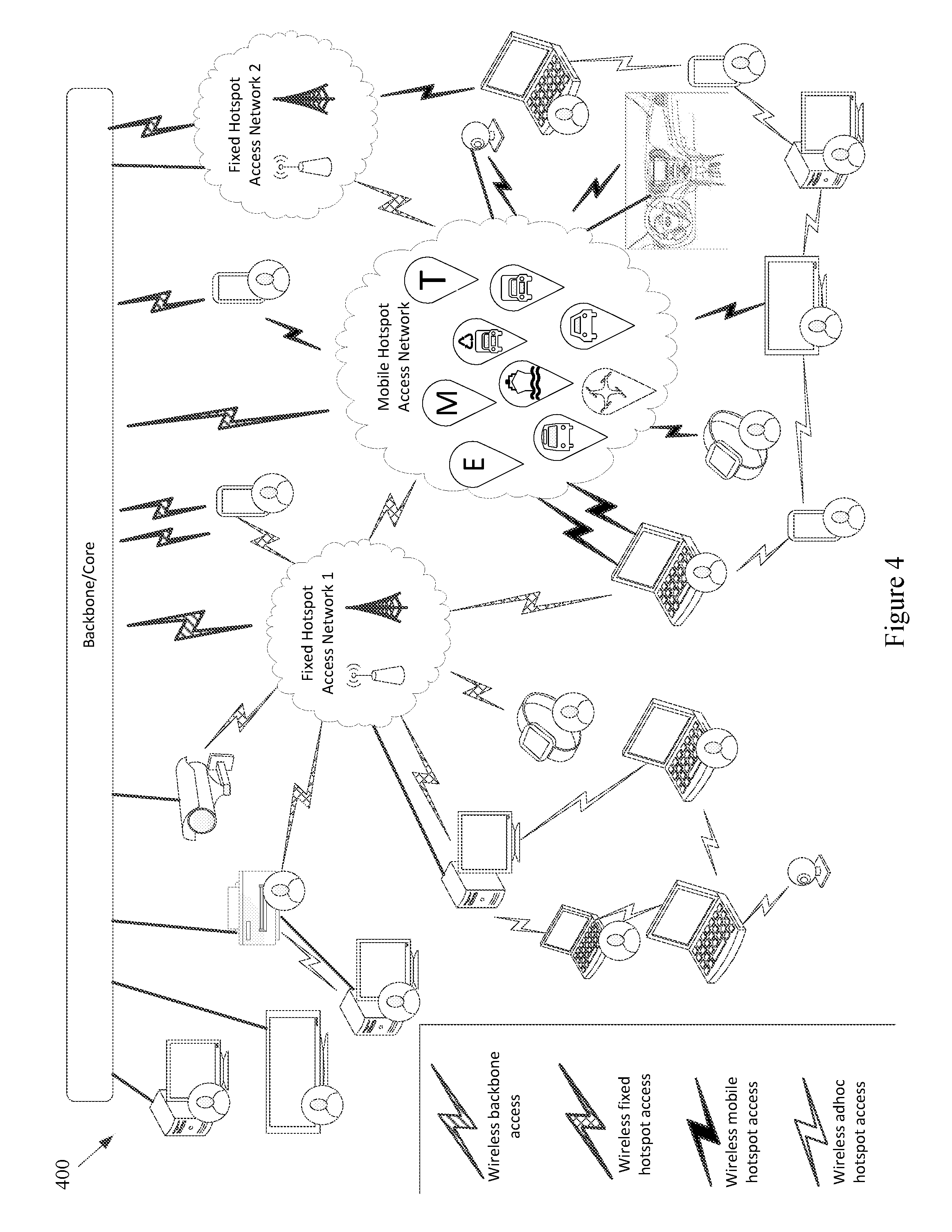
FIG. 4 shows a block diagram of a communication network, in accordance with various aspects of this disclosure.
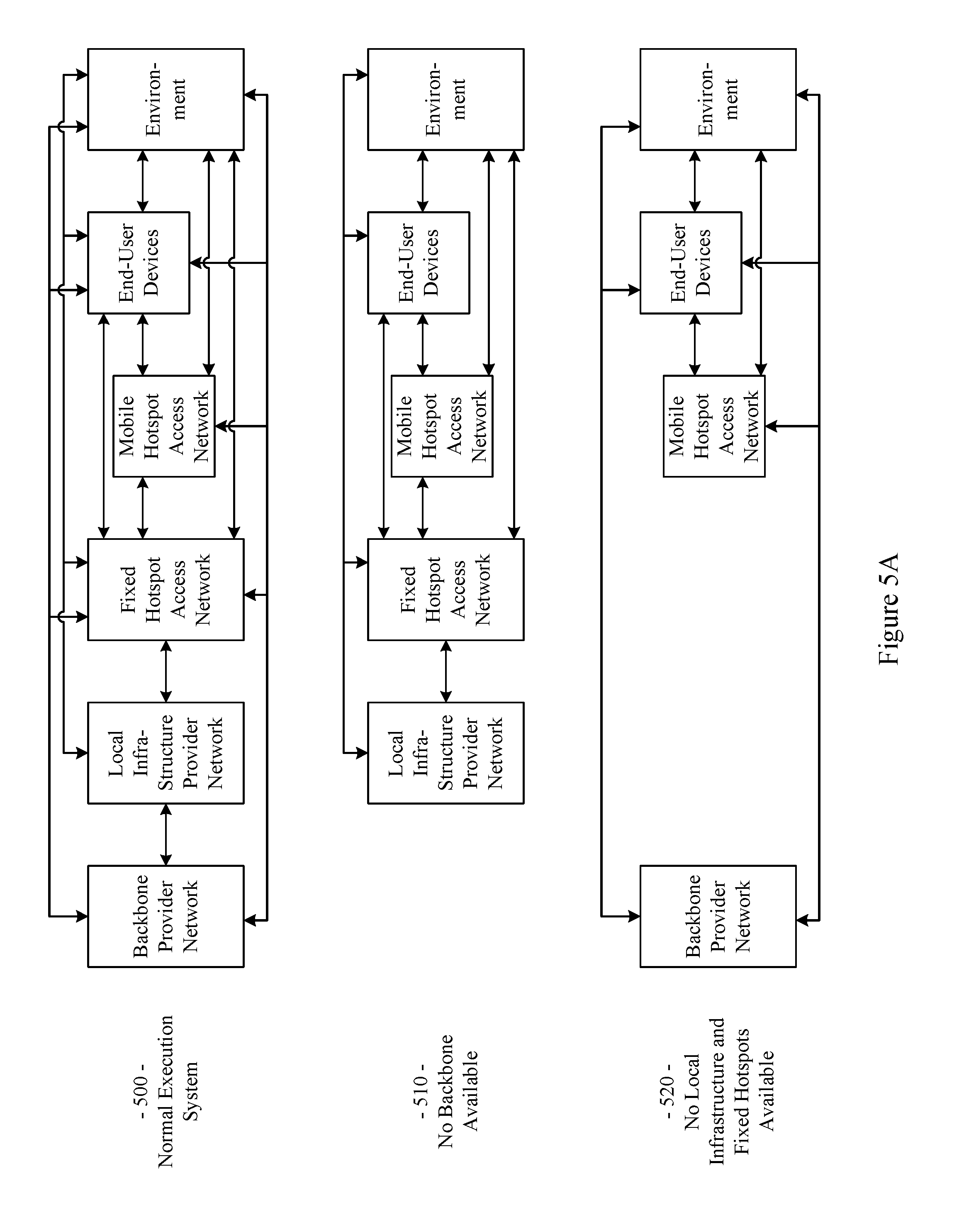
FIGS. 5A-5C show a plurality of network configurations illustrating the flexibility and/or and resiliency of a communication network, in accordance with various aspects of this disclosure.
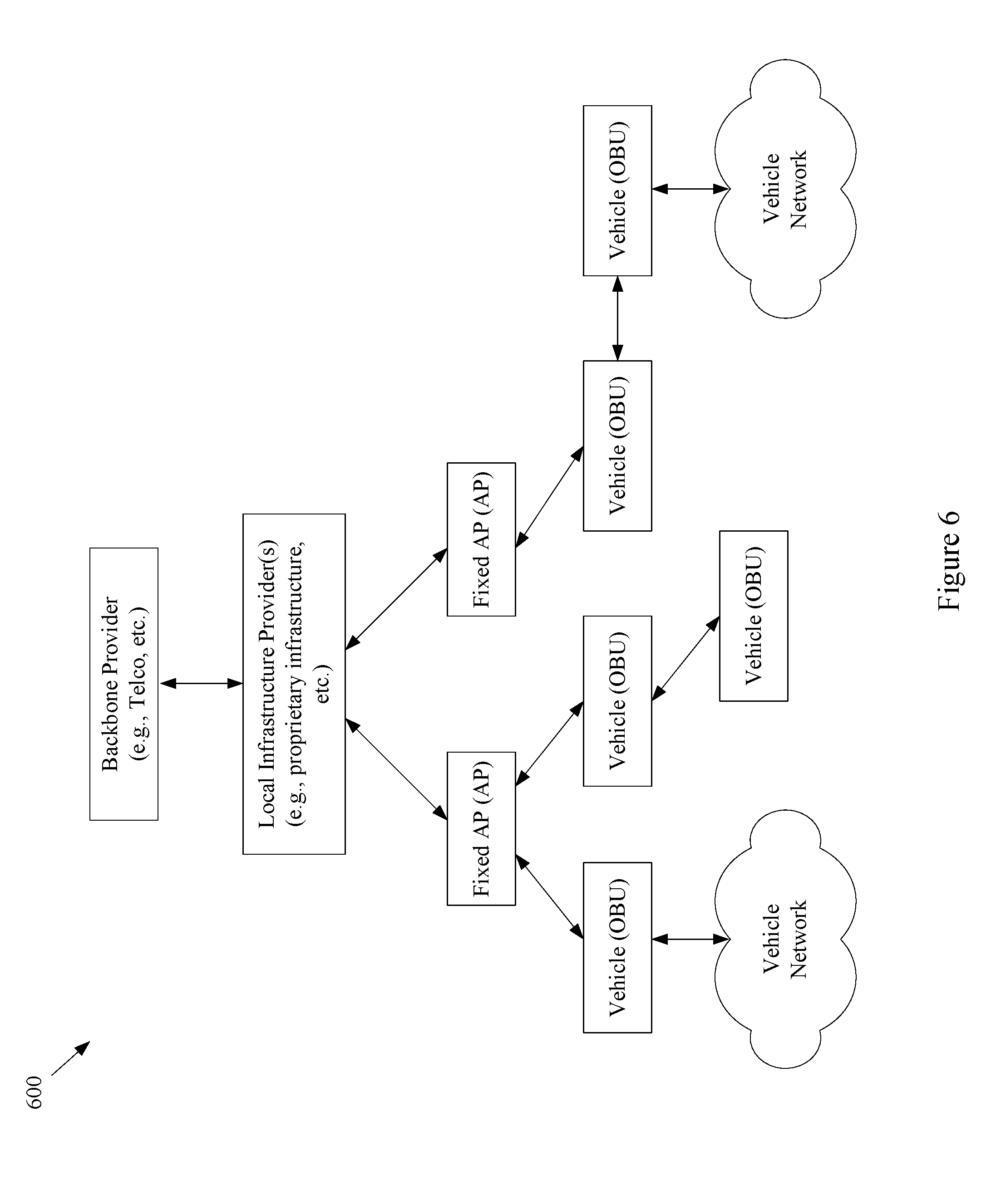
FIG. 6 shows a block diagram of an example communication network, in accordance with various aspects of the present disclosure.
FIG. 7 shows a flow chart of an example process for automatic and self-healing management of antennas in the network of moving things, in accordance with various aspects of the present disclosure.
SUMMARY
Various aspects of this disclosure provide communication network architectures, systems and methods for supporting and/or effectively utilizing a network of mobile and/or static nodes. As a non-limiting example, various aspects of this disclosure provide communication network architectures, systems, and methods for supporting a dynamically configurable communication network comprising a complex array of both static and moving communication nodes (e.g., the Internet of moving things, autonomous vehicle networks, etc.). For example, a communication network implemented in accordance with various aspects of the present disclosure may operate in one of a plurality of modalities comprising various fixed nodes, mobile nodes, and/or a combination thereof, which are selectable to achieve any of a variety of system goals. In example implementation in accordance with the present disclosure, such communication network may be configured to support adaptive management of antennas used in the network.
DETAILED DESCRIPTION OF VARIOUS ASPECTS OF THE DISCLOSURE
As utilized herein the terms "circuits" and "circuitry" refer to physical electronic components (i.e., hardware) and any software and/or firmware ("code") that may configure the hardware, be executed by the hardware, and or otherwise be associated with the hardware. As used herein, for example, a particular processor and memory (e.g., a volatile or non-volatile memory device, a general computer-readable medium, etc.) may comprise a first "circuit" when executing a first one or more lines of code and may comprise a second "circuit" when executing a second one or more lines of code. Additionally, a circuit may comprise analog and/or digital circuitry. Such circuitry may, for example, operate on analog and/or digital signals. It should be understood that a circuit may be in a single device or chip, on a single motherboard, in a single chassis, in a plurality of enclosures at a single geographical location, in a plurality of enclosures distributed over a plurality of geographical locations, etc. Similarly, the term "module" may, for example, refer to a physical electronic components (i.e., hardware) and any software and/or firmware ("code") that may configure the hardware, be executed by the hardware, and or otherwise be associated with the hardware.
As utilized herein, circuitry is "operable" to perform a function whenever the circuitry comprises the necessary hardware and code (if any is necessary) to perform the function, regardless of whether performance of the function is disabled, or not enabled (e.g., by a user-configurable setting, factory setting or trim, etc.).
As utilized herein, "and/or" means any one or more of the items in the list joined by "and/or". As an example, "x and/or y" means any element of the three-element set {(x), (y), (x, y)}. That is, "x and/or y" means "one or both of x and y." As another example, "x, y, and/or z" means any element of the seven-element set {(x), (y), (z), (x, y), (x, z), (y, z), (x, y, z)}. That is, "x, y, and/or z" means "one or more of x, y, and z." As utilized herein, the terms "e.g.," and "for example," "exemplary," and the like set off lists of one or more non-limiting examples, instances, or illustrations.
The terminology used herein is for the purpose of describing particular examples only and is not intended to be limiting of the disclosure. As used herein, the singular forms are intended to include the plural forms as well, unless the context clearly indicates otherwise. It will be further understood that the terms "comprises," "includes," "comprising," "including," "has," "have," "having," and the like when used in this specification, specify the presence of stated features, integers, steps, operations, elements, and/or components, but do not preclude the presence or addition of one or more other features, integers, steps, operations, elements, components, and/or groups thereof.
It will be understood that, although the terms first, second, etc. may be used herein to describe various elements, these elements should not be limited by these terms. These terms are only used to distinguish one element from another element. Thus, for example, a first element, a first component or a first section discussed below could be termed a second element, a second component or a second section without departing from the teachings of the present disclosure. Similarly, various spatial terms, such as "upper," "lower," "side," and the like, may be used in distinguishing one element from another element in a relative manner. It should be understood, however, that components may be oriented in different manners, for example an electronic device may be turned sideways so that its "top" surface is facing horizontally and its "side" surface is facing vertically, without departing from the teachings of the present disclosure.
With the proliferation of the mobile and/or static things (e.g., devices, machines, people, etc.) and logistics for such things to become connected to each other (e.g., in the contexts of smart logistics, transportation, environmental sensing, etc.), a platform that is for example always-on, robust, scalable and secure that is capable of providing connectivity, services and Internet access to such things (or objects), anywhere and anytime is desirable. Efficient power utilization within the various components of such system is also desirable.
Accordingly, various aspects of the present disclosure provide a fully-operable, always-on, responsive, robust, scalable, secure platform/system/architecture to provide connectivity, services and Internet access to all mobile things and/or static things (e.g., devices, machines, people, access points, end user devices, sensors, etc.) anywhere and anytime, while operating in an energy-efficient manner.
Various aspects of the present disclosure provide a platform that is flexibly configurable and adaptable to the various requirements, features, and needs of different environments, where each environment may be characterized by a respective level of mobility and density of mobile and/or static things, and the number and/or types of access to those things. Characteristics of various environments may, for example, include high mobility of nodes (e.g., causing contacts or connections to be volatile), high number of neighbors, high number of connected mobile users, mobile access points, availability of multiple networks and technologies (e.g., sometimes within a same area), etc. For example, the mode of operation of the platform may be flexibly adapted from environment to environment, based on each environment's respective requirements and needs, which may be different from other environments. Additionally for example, the platform may be flexibly optimized (e.g., at design/installation time and/or in real-time) for different purposes (e.g., to reduce the latency, increase throughput, reduce power consumption, load balance, increase reliability, make more robust with regard to failures or other disturbances, etc.), for example based on the content, service or data that the platform provides or handles within a particular environment.
In accordance with various aspects of the present disclosure, many control and management services (e.g., mobility, security, routing, etc.) are provided on top of the platform (e.g., directly, using control overlays, using containers, etc.), such services being compatible with the services currently deployed on top of the Internet or other communication network(s).
The communication network (or platform), in whole or in part, may for example be operated in public and/or private modes of operation, for example depending on the use case. The platform may, for example, operate in a public or private mode of operation, depending on the use-case (e.g., public Internet access, municipal environment sensing, fleet operation, etc.).
Additionally for example, in an implementation in which various network components are mobile, the transportation and/or signal control mechanisms may be adapted to serve the needs of the particular implementation. Also for example, wireless transmission power and/or rate may be adapted (e.g., to mitigate interference, to reduce power consumption, to extend the life of network components, etc.
Various example implementations of a platform, in accordance with various aspects of the present disclosure, are capable of connecting different subsystems, even when various other subsystems that may normally be utilized are unavailable. For example, the platform may comprise various built-in redundancies and fail-recovery mechanisms. For example, the platform may comprise a self-healing capability, self-configuration capability, self-adaptation capability, etc. The protocols and functions of the platform may, for example, be prepared to be autonomously and smoothly configured and adapted to the requirements and features of different environments characterized by different levels of mobility and density of things (or objects), the number/types of access to those things. For example, various aspects of the platform may gather context parameters that can influence any or all decisions. Such parameters may, for example, be derived locally, gathered from a neighborhood, fixed APs, the Cloud, etc. Various aspects of the platform may also, for example, ask for historical information to feed any of the decisions, where such information can be derived from historical data, from surveys, from simulators, etc. Various aspects of the platform may additionally, for example, probe or monitor decisions made throughout the network, for example to evaluate the network and/or the decisions themselves in real-time. Various aspects of the platform may further, for example, enforce the decisions in the network (e.g., after evaluating the probing results). Various aspects of the platform may, for example, establish thresholds to avoid any decision that is to be constantly or repeatedly performed without any significant advantage (e.g., technology change, certificate change, IP change, etc.). Various aspects of the platform may also, for example, learn locally (e.g., with the decisions performed) and dynamically update the decisions.
In addition to (or instead of) failure robustness, a platform may utilize multiple connections (or pathways) that exist between distinct sub-systems or elements within the same sub-system, to increase the robustness and/or load-balancing of the system.
The following discussion will present examples of the functionality performed by various example subsystems of the communication network. It should be understood that the example functionality discussed herein need not be performed by the particular example subsystem or by a single subsystem. For example, the subsystems present herein may interact with each other, and data or control services may be deployed either in a centralized way, or having their functionalities distributed among the different subsystems, for example leveraging the cooperation between the elements of each subsystem.
Various aspects of the present disclosure provide a communication network (e.g., a city-wide vehicular network, a shipping port-sized vehicular network, a campus-wide vehicular network, etc.) that utilizes vehicles (e.g., automobiles, buses, trucks, boats, forklifts, human-operated vehicles, autonomous and/or remote controlled vehicles, etc.) as Wi-Fi hotspots. Note that Wi-Fi is generally used throughout this discussion as an example, but the scope of various aspects of this disclosure is not limited thereto. For example, other wireless LAN technologies, PAN technologies, MAN technologies, etc., may be utilized. Such utilization may, for example, provide cost-effective ways to gather substantial amounts of urban data, and provide for the efficient offloading of traffic from congested cellular networks (or other networks). In controlled areas (e.g., ports, harbors, etc.) with many vehicles, a communication network in accordance with various aspects of this disclosure may expand the wireless coverage of existing enterprise Wi-Fi networks, for example providing for real-time communication with vehicle drivers (e.g., human, computer-controlled, etc.) and other mobile employees without the need for SIM cards or cellular (or other network) data plans.
Vehicles may have many advantageous characteristics that make them useful as Wi-Fi (or general wireless) hotspots. For example, vehicles generally have at least one battery, vehicles are generally densely spread over the city at street level and/or they are able to establish many contacts with each other in a controlled space, and vehicles can communicate with 10.times. the range of normal Wi-Fi in the 5.9 GHz frequency band, reserved for intelligent transportation systems in the EU, the U.S., and elsewhere. Note that the scope of this disclosure is not limited to such 5.9 GHz wireless communication. Further, vehicles are able to effectively expand their coverage area into a swath over a period of time, enabling a single vehicle access point to interact with substantially more data sources over the period of time.
In accordance with various aspects of the present disclosure, an affordable multi-network on-board unit (OBU) is presented. Note that the OBU may also be referred to herein as a mobile access point, Mobile AP, MAP, etc. The OBU may, for example, comprise a plurality of networking interfaces (e.g., Wi-Fi, 802.11p, 4G, Bluetooth, UWB, etc.). The OBU may, for example, be readily installed in or on private and/or public vehicles (e.g., individual user vehicles, vehicles of private fleets, vehicles of public fleets, etc.). The OBU may, for example, be installed in transportation fleets, waste management fleets, law enforcement fleets, emergency services, road maintenance fleets, taxi fleets, aircraft fleets, etc. The OBU may, for example, be installed in or on a vehicle or other structure with free mobility or relatively limited mobility. The OBU may also, for example, be carried by a person or service animal, mounted to a bicycle, mounted to a moving machine in general, mounted to a container, etc.
The OBUs may, for example, operate to connect passing vehicles to the wired infrastructure of one or more network providers, telecom operators, etc. In accordance with the architecture, hardware, and software functionality discussed herein, vehicles and fleets can be connected not just to the cellular networks (or other wide area or metropolitan area networks, etc.) and existing Wi-Fi hotspots spread over a city or a controlled space, but also to other vehicles (e.g., utilizing multi-hop communications to a wired infrastructure, single or multi-hop peer-to-peer vehicle communication, etc.). The vehicles and/or fleets may, for example, form an overall mesh of communication links, for example including the OBUs and also fixed Access Points (APs) connected to the wired infrastructure (e.g., a local infrastructure, etc.). Note that OBUs herein may also be referred to as "Mobile APs," "mobile hotspots," "MAPs," etc. Also note that fixed access points may also be referred to herein as Road Side Units (RSUs), Fixed APs, FAPs, etc.
In an example implementation, the OBUs may communicate with the Fixed APs utilizing a relatively long-range protocol (e.g., 802.11p, etc.), and the Fixed APs may, in turn, be hard wired to the wired infrastructure (e.g., via cable, tethered optical link, etc.). Note that Fixed APs may also, or alternatively, be coupled to the infrastructure via wireless link (e.g., 802.11p, etc.). Additionally, clients or user devices may communicate with the OBUs using one or more relatively short-range protocols (e.g., Wi-Fi, Bluetooth, UWB, etc.). The OBUs, for example having a longer effective wireless communication range than typical Wi-Fi access points or other wireless LAN/PAN access points (e.g., at least for links such as those based on 802.11p, etc.), are capable of substantially greater coverage areas than typical Wi-Fi or other wireless LAN/PAN access points, and thus fewer OBUs are necessary to provide blanket coverage over a geographical area.
The OBU may, for example, comprise a robust vehicular networking module (e.g., a connection manager) which builds on long-range communication protocol capability (e.g., 802.11p, etc.). For example, in addition to comprising 802.11p (or other long-range protocol) capability to communicate with Fixed APs, vehicles, and other nodes in the network, the OBU may comprise a network interface (e.g., 802.11a/b/g/n, 802.11ac, 802.11af, any combination thereof, etc.) to provide wireless local area network (WLAN) connectivity to end user devices, sensors, fixed Wi-Fi access points, etc. For example, the OBU may operate to provide in-vehicle Wi-Fi Internet access to users in and/or around the vehicle (e.g., a bus, train car, taxi cab, public works vehicle, etc.). The OBU may further comprise one or more wireless backbone communication interfaces (e.g., cellular network interfaces, etc.). Though in various example scenarios, a cellular network interface (or other wireless backbone communication interface) might not be the preferred interface for various reasons (e.g., cost, power, bandwidth, etc.), the cellular network interface may be utilized to provide connectivity in geographical areas that are not presently supported by a Fixed AP, may be utilized to provide a fail-over communication link, may be utilized for emergency communications, may be utilized to subscribe to local infrastructure access, etc. The cellular network interface may also, for example, be utilized to allow the deployment of solutions that are dependent on the cellular network operators.
An OBU, in accordance with various aspects of the present disclosure, may for example comprise a smart connection manager that can select the best available wireless link(s) (e.g., Wi-Fi, 802.11p, cellular, vehicle mesh, etc.) with which to access the Internet. The OBU may also, for example, provide geo-location capabilities (e.g., GPS, etc.), motion detection sensors to determine if the vehicle is in motion, and a power control subsystem (e.g., to ensure that the OBU does not deplete the vehicle battery, etc.). The OBU may, for example, comprise any or all of the sensors (e.g., environmental sensors, etc.) discussed herein.
The OBU may also, for example, comprise a manager that manages machine-to-machine data acquisition and transfer (e.g., in a real-time or delay-tolerant fashion) to and from the cloud. For example, the OBU may log and/or communicate information of the vehicles.
The OBU may, for example, comprise a connection and/or routing manager that operates to perform routing of communications in a vehicle-to-vehicle/vehicle-to-infrastructure multi-hop communication. A mobility manager (or controller, MC) may, for example, ensure that communication sessions persist over one or more handoff(s) (also referred to herein as a "handover" or "handovers") (e.g., between different Mobile APs, Fixed APs, base stations, hot spots, etc.), among different technologies (e.g., 802.11p, cellular, Wi-Fi, satellite, etc.), among different MCs (e.g., in a fail-over scenario, load redistribution scenario, etc.), across different interfaces (or ports), etc. Note that the MC may also be referred to herein as a Local Mobility Anchor (LMA), a Network Controller, etc. Note that the MC, or a plurality thereof, may for example be implemented as part of the backbone, but may also, or alternatively, be implemented as part of any of a variety of components or combinations thereof. For example, the MC may be implemented in a Fixed AP (or distributed system thereof), as part of an OBU (or a distributed system thereof), etc. Various non-limiting examples of system components and/or methods are provided in U.S. Provisional Application No. 62/222,098, filed Sep. 22, 2015, and titled "Systems and Method for Managing Mobility in a Network of Moving Things," the entire contents of which are hereby incorporated herein by reference. Note that in an example implementation including a plurality of MCs, such MCs may be co-located and/or may be geographically distributed.
Various aspects of the present disclosure also provide a cloud-based service-oriented architecture that handles the real-time management, monitoring and reporting of the network and clients, the functionalities required for data storage, processing and management, the Wi-Fi client authentication and Captive Portal display, etc.
A communication network (or component thereof) in accordance with various aspects of the present disclosure may, for example, support a wide range of smart city applications (or controlled scenarios, or connected scenarios, etc.) and/or use-cases, as described herein.
For example, an example implementation may operate to turn each vehicle (e.g., both public and private taxis, buses, trucks, etc.) into a Mobile AP (e.g., a mobile Wi-Fi hotspot), offering Internet access to employees, passengers and mobile users travelling in the city, waiting in bus stops, sitting in parks, etc. Moreover, through an example vehicular mesh network formed between vehicles and/or fleets of vehicles, an implementation may be operable to offload cellular traffic through the mobile Wi-Fi hotspots and/or fixed APs (e.g., 802.11p-based APs) spread over the city and connected to the wired infrastructure of public or private telecom operators in strategic places, while ensuring the widest possible coverage at the lowest possible cost.
An example implementation (e.g., of a communication network and/or components thereof) may, for example, be operable as a massive urban scanner that gathers large amounts of data (e.g., continuously) on-the-move, actionable or not, generated by a myriad of sources spanning from the in-vehicle sensors or On Board Diagnostic System port (e.g., OBD2, etc.), interface with an autonomous vehicle driving system, external Wi-Fi/Bluetooth-enabled sensing units spread over the city, devices of vehicles' drivers and passengers (e.g., information characterizing such devices and/or passengers, etc.), positioning system devices (e.g., position information, velocity information, trajectory information, travel history information, etc.), etc.
Depending on the use case, the OBU may for example process (or computer, transform, manipulate, aggregate, summarize, etc.) the data before sending the data from the vehicle, for example providing the appropriate granularity (e.g., value resolution) and sampling rates (e.g., temporal resolution) for each individual application. For example, the OBU may, for example, process the data in any manner deemed advantageous by the system. The OBU may, for example, send the collected data (e.g., raw data, preprocessed data, information of metrics calculated based on the collected data, etc.) to the Cloud (e.g., to one or more networked servers coupled to any portion of the network) in an efficient and reliable manner to improve the efficiency, environmental impact and social value of municipal city operations and transportation services. Various example use cases are described herein.
In an example scenario in which public buses are moving along city routes and/or taxis are performing their private transportation services, the OBU is able to collect large quantities of real-time data from the positioning systems (e.g., GPS, etc.), from accelerometer modules, etc. The OBU may then, for example, communicate such data to the Cloud, where the data may be processed, reported and viewed, for example to support such public or private bus and/or taxi operations, for example supporting efficient remote monitoring and scheduling of buses and taxis, respectively.
In an example implementation, small cameras (or other sensors) may be coupled to small single-board computers (SBCs) that are placed above the doors of public buses to allow capturing image sequences of people entering and leaving buses, and/or on stops along the bus routes in order to estimate the number of people waiting for a bus. Such data may be gathered by the OBU in order to be sent to the Cloud. With such data, public transportation systems may detect peaks; overcrowded buses, routes and stops; underutilized buses, routes and stops; etc., enabling action to be taken in real-time (e.g., reducing bus periodicity to decrease fuel costs and CO.sub.2 emissions where and when passenger flows are smaller, etc.) as well as detecting systematic transportation problems.
An OBU may, for example, be operable to communicate with any of a variety of Wi-Fi-enabled sensor devices equipped with a heterogeneous collection of environmental sensors. Such sensors may, for example, comprise noise sensors (microphones, etc.), gas sensors (e.g., sensing CO, NO.sub.2, O.sub.3, volatile organic compounds (or VOCs), CO.sub.2, etc.), smoke sensors, pollution sensors, meteorological sensors (e.g., sensing temperature, humidity, luminosity, particles, solar radiation, wind speed (e.g., anemometer), wind direction, rain (e.g., a pluviometer), optical scanners, biometric scanners, cameras, microphones, etc.). Such sensors may also comprise sensors associated with users (e.g., vehicle operators or passengers, passersby, etc.) and/or their personal devices (e.g., smart phones or watches, biometrics sensors, wearable sensors, implanted sensors, etc.). Such sensors may, for example, comprise sensors and/or systems associated with on-board diagnostic (OBD) units for vehicles, autonomous vehicle driving systems, etc. Such sensors may, for example, comprise positioning sensors (e.g., GPS sensors, Galileo sensors, GLONASS sensors, etc.). Note that such positioning sensors may be part of a vehicle's operational system (e.g., a local human-controlled vehicle, an autonomous vehicle, a remote human-controlled vehicle, etc.) Such sensors may, for example, comprise container sensors (e.g., garbage can sensors, shipping container sensors, container environmental sensors, container tracking sensors, etc.).
Once a vehicle enters the vicinity of such a sensor device, a wireless link may be established, so that the vehicle (or OBU thereof) can collect sensor data from the sensor device and upload the collected data to a database in the Cloud. The appropriate action can then be taken. In an example waste management implementation, several waste management (or collection) trucks may be equipped with OBUs that are able to periodically communicate with sensors installed on containers in order to gather information about waste level, time passed since last collection, etc. Such information may then sent to the Cloud (e.g., to a waste management application coupled to the Internet, etc.) through the vehicular mesh network, in order to improve the scheduling and/or routing of waste management trucks. Note that various sensors may always be in range of the Mobile AP (e.g., vehicle-mounted sensors). Note that the sensor may also (or alternatively) be mobile (e.g., a sensor mounted to another vehicle passing by a Mobile AP or Fixed AP, a drone-mounted sensor, a pedestrian-mounted sensor, etc.).
In an example implementation, for example in a controlled space (e.g., a port, harbor, airport, factory, plantation, mine, etc.) with many vehicles, machines and employees, a communication network in accordance with various aspects of the present disclosure may expand the wireless coverage of enterprise and/or local Wi-Fi networks, for example without resorting to a Telco-dependent solution based on SIM cards or cellular fees. In such an example scenario, apart from avoiding expensive cellular data plans, limited data rate and poor cellular coverage in some places, a communication network in accordance with various aspects of the present disclosure is also able to collect and/or communicate large amounts of data, in a reliable and real-time manner, where such data may be used to optimize harbor logistics, transportation operations, etc.
For example in a port and/or harbor implementation, by gathering real-time information on the position, speed, fuel consumption and CO.sub.2 emissions of the vehicles, the communication network allows a port operator to improve the coordination of the ship loading processes and increase the throughput of the harbor. Also for example, the communication network enables remote monitoring of drivers' behaviors, behaviors of autonomous vehicles and/or control systems thereof, trucks' positions and engines' status, and then be able to provide real-time notifications to drivers (e.g., to turn on/off the engine, follow the right route inside the harbor, take a break, etc.), for example human drivers and/or automated vehicle driving systems, thus reducing the number and duration of the harbor services and trips. Harbor authorities may, for example, quickly detect malfunctioning trucks and abnormal trucks' circulation, thus avoiding accidents in order to increase harbor efficiency, security, and safety. Additionally, the vehicles can also connect to Wi-Fi access points from harbor local operators, and provide Wi-Fi Internet access to vehicles' occupants and surrounding harbor employees, for example allowing pilots to save time by filing reports via the Internet while still on the water.
Various implementations in accordance with the present disclosure are directed to managing antennas in communication networks comprising static and moving communication nodes (e.g., the Internet of moving things, autonomous vehicle networks, etc.). An example method, in accordance with the present disclosure, may comprise managing antennas in a vehicle communication network comprising one or more mobile access points (MAPs) and one or more fixed access points (FAPs). The managing may comprise selecting an initial antenna setup comprising, for each node in the vehicle communication network, corresponding to one of the one or more MAPs and the one or more FAPs, a corresponding initial node antenna arrangement associated with the node; obtaining information relating to the vehicle communication network and/or operations of the vehicle communication network; determining based on the obtained information if a change to the initial antenna setup is required; and when a change is required: identifying one or more particular node antenna arrangements that are to be modified; determining for each identified node antenna arrangement, one or more corresponding adjustments; and applying the determined adjustments.
In an example implementation, the method may comprise selecting the initial antenna setup based on previously obtained and/or pre-defined information associated with deployment and/or operation of vehicle communication networks.
In an example implementation, the method may comprise determining the initial node antenna arrangement and/or the adjustments, for each node, based on characteristics associated with installation of the node. The characteristics may comprise, when the node may comprise a fixed access point (FAP), physical characteristics associated with a location where the FAB is installed.
In an example implementation, each node antenna arrangement may comprise setting of a number of antennas used for that node antenna arrangement.
In an example implementation, each node antenna arrangement may comprise, for each antenna, a type selection; with the type selection comprising selection of one of an omnidirectional antenna, a sector antenna, or a directional antenna.
In an example implementation, each node antenna arrangement may comprise, for each antenna, a positioning selection; with the positioning selection comprising selection of one of an internal antenna or an external antenna.
In an example implementation, each node antenna arrangement may comprise, for each antenna, one or more configuration parameters; with the one or more configuration parameters relating to one or more of gain, range, throughput, delay, and error performance.
In an example implementation, the initial antenna setup may be configured to optimize performance, based on one or more factors comprising: reducing number of sites for fixed access point (FAP) installation, reducing installation time for each node, increasing overall network coverage, increasing coverage for high traffic areas, and reducing maintenance delays and cost.
An example system, in accordance with the present disclosure, configured for implementing an antenna management scheme in a vehicle communication network comprising one or more mobile access points (MAPs) and one or more fixed access points (FAPs), may comprise one or more communication circuits configured for communication of signals for transmission and reception of data; one or more storage circuits configured for storing of instructions and data; and at least one processing circuit. The at least one processing circuit may be operable to select an initial antenna setup comprising, for each node in the vehicle communication network, corresponding to one of the one or more MAPs and the one or more FAPs, a corresponding initial node antenna arrangement associated with the node. The one or more communication circuits are operable to receive information relating to the vehicle communication network and/or operations of the vehicle communication network, and the at least one processing circuit may be operable process the obtained information and determine, based on the processing, if a change to the initial antenna setup is required. When a change is required, the at least one processing circuit may be operable to: identify one or more particular node antenna arrangements that are to be modified, determine for each identified node antenna arrangement, one or more corresponding adjustments, and generate instructions or control data for applying the determined adjustments.
In an example implementation, the at least one processing circuit may be operable to select the initial antenna setup based on previously obtained and/or pre-defined information associated with deployment and/or operation of vehicle communication networks.
In an example implementation, the at least one processing circuit may be operable to determine the initial node antenna arrangement and/or the adjustments, for each node, based on characteristics associated with installation of the node. The characteristics may comprise, when the node may comprise a fixed access point (FAP), physical characteristics associated with a location where the FAB is installed.
In an example implementation, each node antenna arrangement may comprise setting of a number of antennas used for the node antenna arrangement.
In an example implementation, each node antenna arrangement may comprise, for each antenna, a type selection; with the type selection comprising selection of one from an omnidirectional antenna, a sector antenna, or a directional antenna.
In an example implementation, each node antenna arrangement may comprise, for each antenna, a positioning selection; with the positioning selection comprising selection of one of an internal antenna or an external antenna.
In an example implementation, each node antenna arrangement may comprise, for each antenna, one or more configuration parameters; with the one or more configuration parameters relating to one or more of gain, range, throughput, delay, and error performance.
In an example implementation, the initial antenna setup is configured to optimize performance, based on one or more factors comprising: reducing number of sites for fixed access point (FAP) installation, reducing installation time for each node, increasing overall network coverage, increasing coverage for high traffic areas, and reducing maintenance delays and cost.
An example non-transitory machine-readable storage, in accordance with the present disclosure, may have stored thereon a computer program comprising at least one code section comprising a plurality of instructions executable by a machine comprising at least one processor, to cause the machine to manage antennas in a vehicle communication network by performing a plurality of steps. The vehicle communication network may comprise one or more mobile access points (MAPs) and one or more fixed access points (FAPs). The plurality of steps may comprise: selecting an initial antenna setup comprising, for each node in the vehicle communication network, corresponding to one of the one or more MAPs and the one or more FAPs, a corresponding initial node antenna arrangement associated with the node; obtaining information relating to the vehicle communication network and/or operations of the vehicle communication network; determining based on the obtained information if a change to the initial antenna setup is required; and when a change is required: identifying one or more particular node antenna arrangements that are to be modified; determining for each identified node antenna arrangement, one or more corresponding adjustments; and applying the determined adjustments.
In an example implementation, the plurality of steps may further comprise selecting the initial antenna setup based on previously obtained and/or pre-defined information associated with deployment and/or operation of vehicle communication networks.
In an example implementation, the plurality of steps may further comprise determining the initial node antenna arrangement and/or the adjustments, for each node, based on characteristics associated with installation of the node.
The characteristics may comprise, when the node may comprise a fixed access point (FAP), physical characteristics associated with a location where the FAB is installed.
In an example implementation, each node antenna arrangement may comprise setting of a number of antennas used for the node antenna arrangement.
In an example implementation, each node antenna arrangement may comprise, for each antenna, a type selection; with the type selection comprising selection of one of an omnidirectional antenna, a sector antenna, or a directional antenna.
In an example implementation, each node antenna arrangement may comprise, for each antenna, a positioning selection; with the positioning selection comprising selection of one of an internal antenna or an external antenna.
In an example implementation, each node antenna arrangement may comprise, for each antenna, one or more configuration parameters; with the one or more configuration parameters relating to one or more of gain, range, throughput, delay, and error performance.
In an example implementation, the initial antenna setup is configured to optimize performance, based on one or more factors comprising: reducing number of sites for fixed access point (FAP) installation, reducing installation time for each node, increasing overall network coverage, increasing coverage for high traffic areas, and reducing maintenance delays and cost.
FIG. 1 shows a block diagram of a communication network 100, in accordance with various aspects of this disclosure. Any or all of the functionality discussed herein may be performed by any or all of the example components of the example network 100. Also, the example network 100 (and/or network components) may, for example, share any or all characteristics with the other example networks (and/or network components) 200, 300, 400, 500-570, and 600, discussed herein.
The example network 100, for example, comprises a Cloud that may, for example comprise any of a variety of network level components. The Cloud may, for example, comprise any of a variety of server systems executing applications that monitor and/or control components of the network 100. Such applications may also, for example, manage the collection of information from any of a large array of networked information sources, many examples of which are discussed herein. The Cloud (or a portion thereof) may also be referred to, at times, as an API. For example, Cloud (or a portion thereof) may provide one or more application programming interfaces (APIs) which other devices may use for communicating/interacting with the Cloud.
An example component of the Cloud may, for example, manage interoperability with various multi-cloud systems and architectures. Another example component (e.g., a Cloud service component) may, for example, provide various cloud services (e.g., captive portal services, authentication, authorization, and accounting (AAA) services, API Gateway services, etc.). An additional example component (e.g., a DevCenter component) may, for example, provide network monitoring and/or management functionality, manage the implementation of software updates, etc. A further example component of the Cloud may manage data storage, data analytics, data access, etc. A still further example component of the Cloud may include any of a variety of third-partly applications and services.
The Cloud may, for example, be coupled to the Backbone/Core Infrastructure of the example network 100 via the Internet (e.g., utilizing one or more Internet Service Providers). Though the Internet is provided by example, it should be understood that scope of the present disclosure is not limited thereto.
The Backbone/Core may, for example, comprise any one or more different communication infrastructure components. For example, one or more providers may provide backbone networks or various components thereof. As shown in the example network 100 illustrated in FIG. 1, a Backbone provider may provide wireline access (e.g., PSTN, fiber, cable, etc.). Also for example, a Backbone provider may provide wireless access (e.g., Microwave, LTE/Cellular, 5G/TV Spectrum, etc.).
The Backbone/Core may also, for example, comprise one or more Local Infrastructure Providers. The Backbone/Core may also, for example, comprise a private infrastructure (e.g., run by the network 100 implementer, owner, etc.). The Backbone/Core may, for example, provide any of a variety of Backbone Services (e.g., AAA, Mobility, Monitoring, Addressing, Routing, Content services, Gateway Control services, etc.).
The Backbone/Core Infrastructure may comprise any of a variety of characteristics, non-limiting examples of which are provided herein. For example, the Backbone/Core may be compatible with different wireless or wired technologies for backbone access. The Backbone/Core may also be adaptable to handle public (e.g., municipal, city, campus, etc.) and/or private (e.g., ports, campus, etc.) network infrastructures owned by different local providers, and/or owned by the network implementer or stakeholder. The Backbone/Core may, for example, comprise and/or interface with different Authentication, Authorization, and Accounting (AAA) mechanisms.
The Backbone/Core Infrastructure may, for example, support different modes of operation (e.g., L2 in port implementations, L3 in on-land public transportation implementations, utilizing any one or more of a plurality of different layers of digital IP networking, any combinations thereof, equivalents thereof, etc.) or addressing pools. The Backbone/Core may also for example, be agnostic to the Cloud provider(s) and/or Internet Service Provider(s). Additionally for example, the Backbone/Core may be agnostic to requests coming from any or all subsystems of the network 100 (e.g., Mobile APs or OBUs (On Board Units), Fixed APs or RSUs (Road Side Units), MCs (Mobility Controllers) or LMAs (Local Mobility Anchors) or Network Controllers, etc.) and/or third-party systems.
The Backbone/Core Infrastructure may, for example, comprise the ability to utilize and/or interface with different data storage/processing systems (e.g., MongoDB, MySql, Redis, etc.). The Backbone/Core Infrastructure may further, for example, provide different levels of simultaneous access to the infrastructure, services, data, etc.
The example network 100 may also, for example, comprise a Fixed Hotspot Access Network. Various example characteristics of such a Fixed Hotspot Access Network 200 are shown at FIG. 2. The example network 200 may, for example, share any or all characteristics with the other example networks (and/or network components) 100, 300, 400, 500-570, and 600, discussed herein.
In the example network 200, the Fixed APs (e.g., the proprietary APs, the public third party APs, the private third party APs, etc.) may be directly connected to the local infrastructure provider and/or to the wireline/wireless backbone. Also for example, the example network 200 may comprise a mesh between the various APs via wireless technologies. Note, however, that various wired technologies may also be utilized depending on the implementation. As shown, different fixed hotspot access networks can be connected to a same backbone provider, but may also be connected to different respective backbone providers. In an example implementation utilizing wireless technology for backbone access, such an implementation may be relatively fault tolerant. For example, a Fixed AP may utilize wireless communications to the backbone network (e.g., cellular, 3G, LTE, other wide or metropolitan area networks, etc.) if the backhaul infrastructure is down. Also for example, such an implementation may provide for relatively easy installation (e.g., a Fixed AP with no cable power source that can be placed virtually anywhere).
In the example network 200, the same Fixed AP can simultaneously provide access to multiple Fixed APs, Mobile APs (e.g., vehicle OBUs, etc.), devices, user devices, sensors, things, etc. For example, a plurality of mobile hotspot access networks (e.g., OBU-based networks, etc.) may utilize the same Fixed AP. Also for example, the same Fixed AP can provide a plurality of simultaneous accesses to another single unit (e.g., another Fixed AP, Mobile AP, device, etc.), for example utilizing different channels, different radios, etc.).
Note that a plurality of Fixed APs may be utilized for fault-tolerance/fail-recovery purposes. In an example implementation, a Fixed AP and its fail-over AP may both be normally operational (e.g., in a same switch). Also for example, one or more Fixed APs may be placed in the network at various locations in an inactive or monitoring mode, and ready to become operational when needed (e.g., in response to a fault, in response to an emergency services need, in response to a data surge, etc.).
Referring back to FIG. 1, the example Fixed Hotspot Access Network is shown with a wireless communication link to a backbone provider (e.g., to one or more Backbone Providers and/or Local Infrastructure Providers), to a Mobile Hotspot Access Network, to one or more End User Devices, and to the Environment. Also, the example Fixed Hotspot Access Network is shown with a wired communication link to one or more Backbone Providers, to the Mobile Hotspot Access Network, to one or more End User Devices, and to the Environment. The Environment may comprise any of a variety of devices (e.g., in-vehicle networks, devices, and sensors; autonomous vehicle networks, devices, and sensors; maritime (or watercraft) and port networks, devices, and sensors; general controlled-space networks, devices, and sensors; residential networks, devices, and sensors; disaster recovery & emergency networks, devices, and sensors; military and aircraft networks, devices, and sensors; smart city networks, devices, and sensors; event (or venue) networks, devices, and sensors; underwater and underground networks, devices, and sensors; agricultural networks, devices, and sensors; tunnel (auto, subway, train, etc.) networks, devices, and sensors; parking networks, devices, and sensors; security and surveillance networks, devices, and sensors; shipping equipment and container networks, devices, and sensors; environmental control or monitoring networks, devices, and sensors; municipal networks, devices, and sensors; waste management networks, devices, and sensors, road maintenance networks, devices, and sensors, traffic management networks, devices, and sensors; advertising networks, devices and sensors; etc.).
The example network 100 of FIG. 1 also comprises a Mobile Hotspot Access Network. Various example characteristics of such a Mobile Hotspot Access Network 300 are shown at FIG. 3. Note that various fixed network components (e.g., Fixed APs) are also illustrated. The example network 300 may, for example, share any or all characteristics with the other example networks (and/or network components) 100, 200, 400, 500-570, and 600, discussed herein.
The example network 300 comprises a wide variety of Mobile APs (or hotspots) that provide access to user devices, provide for sensor data collection, provide multi-hop connectivity to other Mobile APs, etc. For example, the example network 300 comprises vehicles from different fleets (e.g., aerial, terrestrial, underground, (under)water, etc.). For example, the example network 300 comprises one or more mass distribution/transportation fleets, one or more mass passenger transportation fleets, private/public shared-user fleets, private vehicles, urban and municipal fleets, maintenance fleets, drones, watercraft (e.g., boats, ships, speedboats, tugboats, barges, etc.), emergency fleets (e.g., police, ambulance, firefighter, etc.), etc.
The example network 300, for example, shows vehicles from different fleets directly connected and/or mesh connected, for example using same or different communication technologies. The example network 300 also shows fleets simultaneously connected to different Fixed APs, which may or may not belong to different respective local infrastructure providers. As a fault-tolerance mechanism, the example network 300 may for example comprise the utilization of long-range wireless communication network (e.g., cellular, 3G, 4G, LTE, etc.) in vehicles if the local network infrastructure is down or otherwise unavailable. A same vehicle (e.g., Mobile AP or OBU) can simultaneously provide access to multiple vehicles, devices, things, etc., for example using a same communication technology (e.g., shared channels and/or different respective channels thereof) and/or using a different respective communication technology for each. Also for example, a same vehicle can provide multiple accesses to another vehicle, device, thing, etc., for example using a same communication technology (e.g., shared channels and/or different respective channels thereof, and/or using a different communication technology).
Additionally, multiple network elements may be connected together to provide for fault-tolerance or fail recovery, increased throughput, or to achieve any or a variety of a client's networking needs, many of examples of which are provided herein. For example, two Mobile APs (or OBUs) may be installed in a same vehicle, etc.
Referring back to FIG. 1, the example Mobile Hotspot Access Network is shown with a wireless communication link to a backbone provider (e.g., to one or more Backbone Providers and/or Local Infrastructure Providers), to a Fixed Hotspot Access Network, to one or more End User Device, and to the Environment (e.g., to any one of more of the sensors or systems discussed herein, any other device or machine, etc.). Though the Mobile Hotspot Access Network is not shown having a wired link to the various other components, there may (at least at times) be such a wired link, at least temporarily.
The example network 100 of FIG. 1 also comprises a set of End-User Devices. Various example end user devices are shown at FIG. 4. Note that various other network components (e.g., Fixed Hotspot Access Networks, Mobile Hotspot Access Network(s), the Backbone/Core, etc.) are also illustrated. The example network 400 may, for example, share any or all characteristics with the other example networks (and/or network components) 100, 200, 300, 500-570, and 600, discussed herein.
The example network 400 shows various mobile networked devices. Such network devices may comprise end-user devices (e.g., smartphones, tablets, smartwatches, laptop computers, webcams, personal gaming devices, personal navigation devices, personal media devices, personal cameras, health-monitoring devices, personal location devices, monitoring panels, printers, etc.). Such networked devices may also comprise any of a variety of devices operating in the general environment, where such devices might not for example be associated with a particular user (e.g. any or all of the sensor devices discussed herein, vehicle sensors, municipal sensors, fleet sensors road sensors, environmental sensors, security sensors, traffic sensors, waste sensors, meteorological sensors, any of a variety of different types of municipal or enterprise equipment, etc.). Any of such networked devices can be flexibly connected to distinct backbone, fixed hotspot access networks, mobile hotspot access networks, etc., using the same or different wired/wireless technologies.
A mobile device may, for example, operate as an AP to provide simultaneous access to multiple devices/things, which may then form ad hoc networks, interconnecting devices ultimately connected to distinct backbone networks, fixed hotspot, and/or mobile hotspot access networks. Devices (e.g., any or all of the devices or network nodes discussed herein) may, for example, have redundant technologies to access distinct backbone, fixed hotspot, and/or mobile hotspot access networks, for example for fault-tolerance and/or load-balancing purposes (e.g., utilizing multiple SIM cards, etc.). A device may also, for example, simultaneously access distinct backbone, fixed hotspot access networks, and/or mobile hotspot access networks, belonging to the same provider or to different respective providers. Additionally for example, a device can provide multiple accesses to another device/thing (e.g., via different channels, radios, etc.).
Referring back to FIG. 1, the example End-User Devices are shown with a wireless communication link to a backbone provider (e.g., to one or more Backbone Providers and/or Local Infrastructure Providers), to a Fixed Hotspot Access Network, to a Mobile Hotspot Access Network, and to the Environment. Also for example, the example End-User Devices are shown with a wired communication link to a backbone provider, to a Fixed Hotspot Access Network, to a Mobile Hotspot Access Network, and to the Environment.
The example network 100 illustrated in FIG. 1 has a flexible architecture that is adaptable at implementation time (e.g., for different use cases) and/or adaptable in real-time, for example as network components enter and leave service. FIGS. 5A-5C illustrate such flexibility by providing example modes (or configurations). The example networks 500-570 may, for example, share any or all characteristics with the other example networks (and/or network components) 100, 200, 300, 400, 600, and 700, discussed herein. For example and without limitation, any or all of the communication links (e.g., wired links, wireless links, etc.) shown in the example networks 500-570 are generally analogous to similarly positioned communication links shown in the example network 100 of FIG. 1.
For example, various aspects of this disclosure provide communication network architectures, systems, and methods for supporting a dynamically configurable communication network comprising a complex array of both static and moving communication nodes (e.g., the Internet of moving things). For example, a communication network implemented in accordance with various aspects of the present disclosure may operate in one of a plurality of modalities comprising various fixed nodes, mobile nodes, and/or a combination thereof, which are selectable to yield any of a variety of system goals (e.g., increased throughput, reduced latency and packet loss, increased availability and robustness of the system, extra redundancy, increased responsiveness, increased security in the transmission of data and/or control packets, reduced number of configuration changes by incorporating smart thresholds (e.g., change of technology, change of certificate, change of IP, etc.), providing connectivity in dead zones or zones with difficult access, reducing the costs for maintenance and accessing the equipment for updating/upgrading, etc.). At least some of such modalities may, for example, be entirely comprised of fixed-position nodes, at least temporarily if not permanently.
For illustrative simplicity, many of the example aspects shown in the example system or network 100 of FIG. 1 (and other Figures herein) are omitted from FIGS. 5A-5C, but may be present. For example, the Cloud, Internet, and ISP aspects shown in FIG. 1 and in other Figures are not explicitly shown in FIGS. 5A-5C, but may be present in any of the example configurations (e.g., as part of the backbone provider network or coupled thereto, as part of the local infrastructure provider network or coupled thereto, etc.).
For example, the first example mode 500 is presented as a normal execution mode, for example a mode (or configuration) in which all of the components discussed herein are present. For example, the communication system in the first example mode 500 comprises a backbone provider network, a local infrastructure provider network, a fixed hotspot access network, a mobile hotspot access network, end-user devices, and environment devices.
As shown in FIG. 5A, and in FIG. 1 in more detail, the backbone provider network may be communicatively coupled to any or all of the other elements present in the first example mode 500 (or configuration) via one or more wired (or tethered) links. For example, the backbone provider network may be communicatively coupled to the local infrastructure provider network (or any component thereof), fixed hotspot access network (or any component thereof), the end-user devices, and/or environment devices via a wired link. Note that such a wired coupling may be temporary. Also note that in various example configurations, the backbone provider network may also, at least temporarily, be communicatively coupled to the mobile hotspot access network (or any component thereof) via one or more wired (or tethered) links.
Also shown in FIG. 5A, and in FIG. 1 in more detail, the backbone provider network may be communicatively coupled to any or all of the other elements present in the first example mode 500 (or configuration) via one or more wireless links (e.g., RF link, non-tethered optical link, etc.). For example, the backbone provider network may be communicatively coupled to the fixed hotspot access network (or any component thereof), the mobile hotspot access network (or any component thereof), the end-user devices, and/or environment devices via one or more wireless links. Also note that in various example configurations, the backbone provider network may also be communicatively coupled to the local infrastructure provider network via one or more wireless (or non-tethered) links.
Though not shown in the first example mode 500 (or any of the example modes of FIGS. 5A-5C), one or more servers may be communicatively coupled to the backbone provider network and/or the local infrastructure network. FIG. 1 provides an example of cloud servers being communicatively coupled to the backbone provider network via the Internet.
As additionally shown in FIG. 5A, and in FIG. 1 in more detail, the local infrastructure provider network may be communicatively coupled to any or all of the other elements present in the first example mode 500 (or configuration) via one or more wired (or tethered) links. For example, the local infrastructure provider network may be communicatively coupled to the backbone provider network (or any component thereof), fixed hotspot access network (or any component thereof), the end-user devices, and/or environment devices via one or more wired links. Note that such a wired coupling may be temporary. Also note that in various example configurations, the local infrastructure provider network may also, at least temporarily, be communicatively coupled to the mobile hotspot access network (or any component thereof) via one or more wired (or tethered) links.
Also, though not explicitly shown, the local infrastructure provider network may be communicatively coupled to any or all of the other elements present in the first example mode 500 (or configuration) via one or more wireless links (e.g., RF link, non-tethered optical link, etc.). For example, the local infrastructure provider network may be communicatively coupled to the backbone provider network (or any component thereof), the fixed hotspot access network (or any component thereof), the mobile hotspot access network (or any component thereof), the end-user devices, and/or environment devices via one or more wireless links. Note that the communication link shown in the first example mode 500 of FIG. 5A between the local infrastructure provider network and the fixed hotspot access network may be wired and/or wireless.
The fixed hotspot access network is also shown in the first example mode 500 to be communicatively coupled to the mobile hotspot access network, the end-user devices, and/or environment devices via one or more wireless links. Many examples of such wireless coupling are provided herein. Additionally, the mobile hotspot access network is further shown in the first example mode 500 to be communicatively coupled to the end-user devices and/or environment devices via one or more wireless links. Many examples of such wireless coupling are provided herein. Further, the end-user devices are also shown in the first example mode 500 to be communicatively coupled to the environment devices via one or more wireless links. Many examples of such wireless coupling are provided herein. Note that in various example implementations any of such wireless links may instead (or in addition) comprise a wired (or tethered) link.
In the first example mode 500 (e.g., the normal mode), information (or data) may be communicated between an end-user device and a server (e.g., a computer system) via the mobile hotspot access network, the fixed hotspot access network, the local infrastructure provider network, and/or the backbone provider network. As will be seen in the various example modes presented herein, such communication may flexibly occur between an end-user device and a server via any of a variety of different communication pathways, for example depending on the availability of a network, depending on bandwidth utilization goals, depending on communication priority, depending on communication time (or latency) and/or reliability constraints, depending on cost, etc. For example, information communicated between an end user device and a server may be communicated via the fixed hotspot access network, the local infrastructure provider network, and/or the backbone provider network (e.g., skipping the mobile hotspot access network). Also for example, information communicated between an end user device and a server may be communicated via the backbone provider network (e.g., skipping the mobile hotspot access network, fixed hotspot access network, and/or local infrastructure provider network).
Similarly, in the first example mode 500 (e.g., the normal mode), information (or data) may be communicated between an environment device and a server via the mobile hotspot access network, the fixed hotspot access network, the local infrastructure provider network, and/or the backbone provider network. Also for example, an environment device may communicate with or through an end-user device (e.g., instead of or in addition to the mobile hotspot access network). As will be seen in the various example modes presented herein, such communication may flexibly occur between an environment device and a server (e.g., communicatively coupled to the local infrastructure provider network and/or backbone provider network) via any of a variety of different communication pathways, for example depending on the availability of a network, depending on bandwidth utilization goals, depending on communication priority, depending on communication time (or latency) and/or reliability constraints, depending on cost, etc.
For example, information communicated between an environment device and a server may be communicated via the fixed hotspot access network, the local infrastructure provider network, and/or the backbone provider network (e.g., skipping the mobile hotspot access network). Also for example, information communicated between an environment device and a server may be communicated via the backbone provider network (e.g., skipping the mobile hotspot access network, fixed hotspot access network, and/or local infrastructure provider network). Additionally for example, information communicated between an environment device and a server may be communicated via the local infrastructure provider network (e.g., skipping the mobile hotspot access network and/or fixed hotspot access network).
As discussed herein, the example networks presented herein are adaptively configurable to operate in any of a variety of different modes (or configurations). Such adaptive configuration may occur at initial installation and/or during subsequent controlled network evolution (e.g., adding or removing any or all of the network components discussed herein, expanding or removing network capacity, adding or removing coverage areas, adding or removing services, etc.). Such adaptive configuration may also occur in real-time, for example in response to real-time changes in network conditions (e.g., networks or components thereof being available or not based on vehicle or user-device movement, network or component failure, network or component replacement or augmentation activity, network overloading, etc.). The following example modes are presented to illustrate characteristics of various modes in which a communication system may operate in accordance with various aspects of the present disclosure. The following example modes will generally be discussed in relation to the first example mode 500 (e.g., the normal execution mode). Note that such example modes are merely illustrative and not limiting.
The second example mode (or configuration) 510 (e.g., a no backbone available mode) may, for example, share any or all characteristics with the first example mode 500, albeit without the backbone provider network and communication links therewith. For example, the communication system in the second example mode 510 comprises a local infrastructure provider network, a fixed hotspot access network, a mobile hotspot access network, end-user devices, and environment devices.
As shown in FIG. 5A, and in FIG. 1 in more detail, the local infrastructure provider network may be communicatively coupled to any or all of the other elements present in the second example mode 510 (or configuration) via one or more wired (or tethered) links. For example, the local infrastructure provider network may be communicatively coupled to the fixed hotspot access network (or any component thereof), the end-user devices, and/or environment devices via one or more wired links. Note that such a wired coupling may be temporary. Also note that in various example configurations, the local infrastructure provider network may also, at least temporarily, be communicatively coupled to the mobile hotspot access network (or any component thereof) via one or more wired (or tethered) links.
Also, though not explicitly shown, the local infrastructure provider network may be communicatively coupled to any or all of the other elements present in the second example mode 510 (or configuration) via one or more wireless links (e.g., RF link, non-tethered optical link, etc.). For example, the local infrastructure provider network may be communicatively coupled to the fixed hotspot access network (or any component thereof), the mobile hotspot access network (or any component thereof), the end-user devices, and/or environment devices via one or more wireless links. Note that the communication link(s) shown in the second example mode 510 of FIG. 5A between the local infrastructure provider network and the fixed hotspot access network may be wired and/or wireless.
The fixed hotspot access network is also shown in the second example mode 510 to be communicatively coupled to the mobile hotspot access network, the end-user devices, and/or environment devices via one or more wireless links. Many examples of such wireless coupling are provided herein. Additionally, the mobile hotspot access network is further shown in the second example mode 510 to be communicatively coupled to the end-user devices and/or environment devices via one or more wireless links. Many examples of such wireless coupling are provided herein. Further, the end-user devices are also shown in the second example mode 510 to be communicatively coupled to the environment devices via one or more wireless links. Many examples of such wireless coupling are provided herein. Note that in various example implementations any of such wireless links may instead (or in addition) comprise a wired (or tethered) link.
In the second example mode 510 (e.g., the no backbone available mode), information (or data) may be communicated between an end-user device and a server (e.g., a computer, etc.) via the mobile hotspot access network, the fixed hotspot access network, and/or the local infrastructure provider network. As will be seen in the various example modes presented herein, such communication may flexibly occur between an end-user device and a server via any of a variety of different communication pathways, for example depending on the availability of a network, depending on bandwidth utilization goals, depending on communication priority, depending on communication time (or latency) and/or reliability constraints, depending on cost, etc. For example, information communicated between an end user device and a server may be communicated via the fixed hotspot access network and/or the local infrastructure provider network (e.g., skipping the mobile hotspot access network). Also for example, information communicated between an end user device and a server may be communicated via the local infrastructure provider network (e.g., skipping the mobile hotspot access network and/or fixed hotspot access network).
Similarly, in the second example mode 510 (e.g., the no backbone available mode), information (or data) may be communicated between an environment device and a server via the mobile hotspot access network, the fixed hotspot access network, and/or the local infrastructure provider network. Also for example, an environment device may communicate with or through an end-user device (e.g., instead of or in addition to the mobile hotspot access network). As will be seen in the various example modes presented herein, such communication may flexibly occur between an environment device and a server (e.g., communicatively coupled to the local infrastructure provider network) via any of a variety of different communication pathways, for example depending on the availability of a network, depending on bandwidth utilization goals, depending on communication priority, depending on communication time (or latency) and/or reliability constraints, depending on cost, etc.
For example, information communicated between an environment device and a server may be communicated via the fixed hotspot access network and/or the local infrastructure provider network (e.g., skipping the mobile hotspot access network). Also for example, information communicated between an environment device and a server may be communicated via the local infrastructure provider network (e.g., skipping the mobile hotspot access network and/or fixed hotspot access network).
The second example mode 510 may be utilized for any of a variety of reasons, non-limiting examples of which are provided herein. For example, due to security and/or privacy goals, the second example mode 510 may be utilized so that communication access to the public Cloud systems, the Internet in general, etc., is not allowed. For example, all network control and management functions may be within the local infrastructure provider network (e.g., wired local network, etc.) and/or the fixed access point network.
In an example implementation, the communication system might be totally owned, operated and/or controlled by a local port authority. No extra expenses associated with cellular connections need be spent. For example, cellular connection capability (e.g., in Mobile APs, Fixed APs, end user devices, environment devices, etc.) need not be provided. Note also that the second example mode 510 may be utilized in a scenario in which the backbone provider network is normally available but is currently unavailable (e.g., due to server failure, due to communication link failure, due to power outage, due to a temporary denial of service, etc.).
The third example mode (or configuration) 520 (e.g., a no local infrastructure and fixed hotspots available mode) may, for example, share any or all characteristics with the first example mode 500, albeit without the local infrastructure provider network, the fixed hotspot access network, and communication links therewith. For example, the communication system in the third example mode 520 comprises a backbone provider network, a mobile hotspot access network, end-user devices, and environment devices.
As shown in FIG. 5A, and in FIG. 1 in more detail, the backbone provider network may be communicatively coupled to any or all of the other elements present in the third example mode 520 (or configuration) via one or more wired (or tethered) links. For example, the backbone provider network may be communicatively coupled to the end-user devices and/or environment devices via one or more wired links. Note that such a wired coupling may be temporary. Also note that in various example configurations, the backbone provider network may also, at least temporarily, be communicatively coupled to the mobile hotspot access network (or any component thereof) via one or more wired (or tethered) links.
Also shown in FIG. 5A, and in FIG. 1 in more detail, the backbone provider network may be communicatively coupled to any or all of the other elements present in the third example mode 520 (or configuration) via one or more wireless links (e.g., RF link, non-tethered optical link, etc.). For example, the backbone provider network may be communicatively coupled to the mobile hotspot access network (or any component thereof), the end-user devices, and/or environment devices via one or more wireless links.
The mobile hotspot access network is further shown in the third example mode 520 to be communicatively coupled to the end-user devices and/or environment devices via one or more wireless links. Many examples of such wireless coupling are provided herein. Further, the end-user devices are also shown in the third example mode 520 to be communicatively coupled to the environment devices via one or more wireless links. Many examples of such wireless coupling are provided herein. Note that in various example implementations any of such wireless links may instead (or in addition) comprise a wired (or tethered) link.
In the third example mode 520 (e.g., the no local infrastructure and fixed hotspots available mode), information (or data) may be communicated between an end-user device and a server (e.g., a computer, etc.) via the mobile hotspot access network and/or the backbone provider network. As will be seen in the various example modes presented herein, such communication may flexibly occur between an end-user device and a server via any of a variety of different communication pathways, for example depending on the availability of a network, depending on bandwidth utilization goals, depending on communication priority, depending on communication time (or latency) and/or reliability constraints, depending on cost, etc. For example, information communicated between an end user device and a server may be communicated via the backbone provider network (e.g., skipping the mobile hotspot access network).
Similarly, in the third example mode 520 (e.g., the no local infrastructure and fixed hotspots available mode), information (or data) may be communicated between an environment device and a server via the mobile hotspot access network and/or the backbone provider network. Also for example, an environment device may communicate with or through an end-user device (e.g., instead of or in addition to the mobile hotspot access network). As will be seen in the various example modes presented herein, such communication may flexibly occur between an environment device and a server (e.g., communicatively coupled to the backbone provider network) via any of a variety of different communication pathways, for example depending on the availability of a network, depending on bandwidth utilization goals, depending on communication priority, depending on communication time (or latency) and/or reliability constraints, depending on cost, etc. For example, information communicated between an environment device and a server may be communicated via the backbone provider network (e.g., skipping the mobile hotspot access network).
In the third example mode 520, all control/management functions may for example be implemented within the Cloud. For example, since the mobile hotspot access network does not have a communication link via a fixed hotspot access network, the Mobile APs may utilize a direct connection (e.g., a cellular connection) with the backbone provider network (or Cloud). If a Mobile AP does not have such capability, the Mobile AP may also, for example, utilize data access provided by the end-user devices communicatively coupled thereto (e.g., leveraging the data plans of the end-user devices).
The third example mode 520 may be utilized for any of a variety of reasons, non-limiting examples of which are provided herein. In an example implementation, the third example mode 520 may be utilized in an early stage of a larger deployment, for example deployment that will grow into another mode (e.g., the example first mode 500, example fourth mode 530, etc.) as more communication system equipment is installed. Note also that the third example mode 520 may be utilized in a scenario in which the local infrastructure provider network and fixed hotspot access network are normally available but are currently unavailable (e.g., due to equipment failure, due to communication link failure, due to power outage, due to a temporary denial of service, etc.).
The fourth example mode (or configuration) 530 (e.g., a no fixed hotspots available mode) may, for example, share any or all characteristics with the first example mode 500, albeit without the fixed hotspot access network and communication links therewith. For example, the communication system in the fourth example mode 530 comprises a backbone provider network, a local infrastructure provider network, a mobile hotspot access network, end-user devices, and environment devices.
As shown in FIG. 5B, and in FIG. 1 in more detail, the backbone provider network may be communicatively coupled to any or all of the other elements present in the fourth example mode 530 (or configuration) via one or more wired (or tethered) links. For example, the backbone provider network may be communicatively coupled to the local infrastructure provider network (or any component thereof), the end-user devices, and/or environment devices via one or more wired links. Note that such a wired coupling may be temporary. Also note that in various example configurations, the backbone provider network may also, at least temporarily, be communicatively coupled to the mobile hotspot access network (or any component thereof) via one or more wired (or tethered) links.
Also shown in FIG. 5B, and in FIG. 1 in more detail, the backbone provider network may be communicatively coupled to any or all of the other elements present in the fourth example mode 530 (or configuration) via one or more wireless links (e.g., RF link, non-tethered optical link, etc.). For example, the backbone provider network may be communicatively coupled to the mobile hotspot access network (or any component thereof), the end-user devices, and/or environment devices via one or more wireless links. Also note that in various example configurations, the backbone provider network may also be communicatively coupled to the local infrastructure provider network via one or more wireless (or non-tethered) links.
As additionally shown in FIG. 5B, and in FIG. 1 in more detail, the local infrastructure provider network may be communicatively coupled to any or all of the other elements present in the fourth example mode 530 (or configuration) via one or more wired (or tethered) links. For example, the local infrastructure provider network may be communicatively coupled to the backbone provider network (or any component thereof), the end-user devices, and/or environment devices via one or more wired links. Note that such a wired coupling may be temporary. Also note that in various example configurations, the local infrastructure provider network may also, at least temporarily, be communicatively coupled to the mobile hotspot access network (or any component thereof) via one or more wired (or tethered) links.
Also, though not explicitly shown, the local infrastructure provider network may be communicatively coupled to any or all of the other elements present in the fourth example mode 530 (or configuration) via one or more wireless links (e.g., RF link, non-tethered optical link, etc.). For example, the local infrastructure provider network may be communicatively coupled to the backbone provider network (or any component thereof), the mobile hotspot access network (or any component thereof), the end-user devices, and/or environment devices via one or more wireless links.
The mobile hotspot access network is further shown in the fourth example mode 530 to be communicatively coupled to the end-user devices and/or environment devices via one or more wireless links. Many examples of such wireless coupling are provided herein. Further, the end-user devices are also shown in the fourth example mode 530 to be communicatively coupled to the environment devices via one or more wireless links. Many examples of such wireless coupling are provided herein.
In the fourth example mode 530 (e.g., the no fixed hotspots mode), information (or data) may be communicated between an end-user device and a server via the mobile hotspot access network, the local infrastructure provider network, and/or the backbone provider network. As will be seen in the various example modes presented herein, such communication may flexibly occur between an end-user device and a server via any of a variety of different communication pathways, for example depending on the availability of a network, depending on bandwidth utilization goals, depending on communication priority, depending on communication time (or latency) and/or reliability constraints, depending on cost, etc. For example, information communicated between an end user device and a server may be communicated via the local infrastructure provider network and/or the backbone provider network (e.g., skipping the mobile hotspot access network). Also for example, information communicated between an end user device and a server may be communicated via the backbone provider network (e.g., skipping the mobile hotspot access network and/or local infrastructure provider network).
Similarly, in the fourth example mode 530 (e.g., the no fixed hotspots available mode), information (or data) may be communicated between an environment device and a server via the mobile hotspot access network, the local infrastructure provider network, and/or the backbone provider network. Also for example, an environment device may communicate with or through an end-user device (e.g., instead of or in addition to the mobile hotspot access network). As will be seen in the various example modes presented herein, such communication may flexibly occur between an environment device and a server (e.g., communicatively coupled to the local infrastructure provider network and/or backbone provider network) via any of a variety of different communication pathways, for example depending on the availability of a network, depending on bandwidth utilization goals, depending on communication priority, depending on communication time (or latency) and/or reliability constraints, depending on cost, etc.
For example, information communicated between an environment device and a server may be communicated via the local infrastructure provider network and/or the backbone provider network (e.g., skipping the mobile hotspot access network). Also for example, information communicated between an environment device and a server may be communicated via the backbone provider network (e.g., skipping the mobile hotspot access network and/or local infrastructure provider network). Additionally for example, information communicated between an environment device and a server may be communicated via the local infrastructure provider network (e.g., skipping the mobile hotspot access network and/or backbone provider network).
In the fourth example mode 530, in an example implementation, some of the control/management functions may for example be implemented within the local backbone provider network (e.g., within a client premises). For example, communication to the local infrastructure provider may be performed through the backbone provider network (or Cloud). Note that in a scenario in which there is a direct communication pathway between the local infrastructure provider network and the mobile hotspot access network, such communication pathway may be utilized.
For example, since the mobile hotspot access network does not have a communication link via a fixed hotspot access network, the Mobile APs may utilize a direct connection (e.g., a cellular connection) with the backbone provider network (or Cloud). If a Mobile AP does not have such capability, the Mobile AP may also, for example, utilize data access provided by the end-user devices communicatively coupled thereto (e.g., leveraging the data plans of the end-user devices).
The fourth example mode 530 may be utilized for any of a variety of reasons, non-limiting examples of which are provided herein. In an example implementation, the fourth example mode 530 may be utilized in an early stage of a larger deployment, for example a deployment that will grow into another mode (e.g., the example first mode 500, etc.) as more communication system equipment is installed. The fourth example mode 530 may, for example, be utilized in a scenario in which there is no fiber (or other) connection available for Fixed APs (e.g., in a maritime scenario, in a plantation scenario, etc.), or in which a Fixed AP is difficult to access or connect. For example, one or more Mobile APs of the mobile hotspot access network may be used as gateways to reach the Cloud. The fourth example mode 530 may also, for example, be utilized when a vehicle fleet and/or the Mobile APs associated therewith are owned by a first entity and the Fixed APs are owned by another entity, and there is no present agreement for communication between the Mobile APs and the Fixed APs. Note also that the fourth example mode 530 may be utilized in a scenario in which the fixed hotspot access network is normally available but are currently unavailable (e.g., due to equipment failure, due to communication link failure, due to power outage, due to a temporary denial of service, etc.).
The fifth example mode (or configuration) 540 (e.g., a no mobile hotspots available mode) may, for example, share any or all characteristics with the first example mode 500, albeit without the mobile hotspot access network and communication links therewith. For example, the communication system in the fifth example mode 540 comprises a backbone provider network, a local infrastructure provider network, a fixed hotspot access network, end-user devices, and environment devices.
As shown in FIG. 5B, and in FIG. 1 in more detail, the backbone provider network may be communicatively coupled to any or all of the other elements present in the fifth example mode 540 (or configuration) via one or more wired (or tethered) links. For example, the backbone provider network may be communicatively coupled to the local infrastructure provider network (or any component thereof), fixed hotspot access network (or any component thereof), the end-user devices, and/or environment devices via one or more wired links. Note that such a wired coupling may be temporary.
Also shown in FIG. 5B, and in FIG. 1 in more detail, the backbone provider network may be communicatively coupled to any or all of the other elements present in the fifth example mode 540 (or configuration) via one or more wireless links (e.g., RF link, non-tethered optical link, etc.). For example, the backbone provider network may be communicatively coupled to the fixed hotspot access network (or any component thereof), the end-user devices, and/or environment devices via one or more wireless links. Also note that in various example configurations, the backbone provider network may also be communicatively coupled to the local infrastructure provider network via one or more wireless (or non-tethered) links.
As additionally shown in FIG. 5B, and in FIG. 1 in more detail, the local infrastructure provider network may be communicatively coupled to any or all of the other elements present in the fifth example mode 540 (or configuration) via one or more wired (or tethered) links. For example, the local infrastructure provider network may be communicatively coupled to the backbone provider network (or any component thereof), fixed hotspot access network (or any component thereof), the end-user devices, and/or environment devices via one or more wired links. Note that such a wired coupling may be temporary. Also note that in various example configurations, the local infrastructure provider network may also, at least temporarily, be communicatively coupled to the mobile hotspot access network (or any component thereof) via one or more wired (or tethered) links.
Also, though not explicitly shown, the local infrastructure provider network may be communicatively coupled to any or all of the other elements present in the fifth example mode 540 (or configuration) via one or more wireless links (e.g., RF link, non-tethered optical link, etc.). For example, the local infrastructure provider network may be communicatively coupled to the backbone provider network, the fixed hotspot access network (or any component thereof), the end-user devices, and/or environment devices via one or more wireless links. Note that the communication link(s) shown in the fifth example mode 540 of FIG. 5B between the local infrastructure provider network and the fixed hotspot access network may be wired and/or wireless.
The fixed hotspot access network is also shown in the fifth example mode 540 to be communicatively coupled to the end-user devices and/or environment devices via one or more wireless links. Many examples of such wireless coupling are provided herein. Further, the end-user devices are also shown in the fifth example mode 540 to be communicatively coupled to the environment devices via one or more wireless links. Many examples of such wireless coupling are provided herein.
In the fifth example mode 540 (e.g., the no mobile hotspots available mode), information (or data) may be communicated between an end-user device and a server via the fixed hotspot access network, the local infrastructure provider network, and/or the backbone provider network. As will be seen in the various example modes presented herein, such communication may flexibly occur between an end-user device and a server via any of a variety of different communication pathways, for example depending on the availability of a network, depending on bandwidth utilization goals, depending on communication priority, depending on communication time (or latency) and/or reliability constraints, depending on cost, etc. For example, information communicated between an end user device and a server may be communicated via the local infrastructure provider network, and/or the backbone provider network (e.g., skipping the fixed hotspot access network). Also for example, information communicated between an end user device and a server may be communicated via the backbone provider network (e.g., skipping the fixed hotspot access network and/or local infrastructure provider network).
Similarly, in the fifth example mode 540 (e.g., the no mobile hotspots available mode), information (or data) may be communicated between an environment device and a server via the fixed hotspot access network, the local infrastructure provider network, and/or the backbone provider network. Also for example, an environment device may communicate with or through an end-user device (e.g., instead of or in addition to the fixed hotspot access network). As will be seen in the various example modes presented herein, such communication may flexibly occur between an environment device and a server (e.g., communicatively coupled to the local infrastructure provider network and/or backbone provider network) via any of a variety of different communication pathways, for example depending on the availability of a network, depending on bandwidth utilization goals, depending on communication priority, depending on communication time (or latency) and/or reliability constraints, depending on cost, etc.
For example, information communicated between an environment device and a server may be communicated via the local infrastructure provider network and/or the backbone provider network (e.g., skipping the fixed hotspot access network). Also for example, information communicated between an environment device and a server may be communicated via the backbone provider network (e.g., skipping the fixed hotspot access network and/or local infrastructure provider network). Additionally for example, information communicated between an environment device and a server may be communicated via the local infrastructure provider network (e.g., skipping the fixed hotspot access network and/or the backbone provider network).
In the fifth example mode 540, in an example implementation, the end-user devices and environment devices may communicate directly to Fixed APs (e.g., utilizing Ethernet, Wi-Fi, etc.). Also for example, the end-user devices and/or environment devices may communicate directly with the backbone provider network (e.g., utilizing cellular connections, etc.).
The fifth example mode 540 may be utilized for any of a variety of reasons, non-limiting examples of which are provided herein. In an example implementation in which end-user devices and/or environment devices may communicate directly with Fixed APs, such communication may be utilized instead of Mobile AP communication. For example, the fixed hotspot access network might provide coverage for all desired areas.
Note also that the fifth example mode 540 may be utilized in a scenario in which the fixed hotspot access network is normally available but is currently unavailable (e.g., due to equipment failure, due to communication link failure, due to power outage, due to a temporary denial of service, etc.).
The sixth example mode (or configuration) 550 (e.g., the no fixed/mobile hotspots and local infrastructure available mode) may, for example, share any or all characteristics with the first example mode 500, albeit without the local infrastructure provider network, fixed hotspot access network, mobile hotspot access network, and communication links therewith. For example, the communication system in the sixth example mode 550 comprises a backbone provider network, end-user devices, and environment devices.
As shown in FIG. 5B, and in FIG. 1 in more detail, the backbone provider network may be communicatively coupled to any or all of the other elements present in the sixth example mode 550 (or configuration) via one or more wired (or tethered) links. For example, the backbone provider network may be communicatively coupled to the end-user devices and/or environment devices via one or more wired links. Note that such a wired coupling may be temporary.
Also shown in FIG. 5B, and in FIG. 1 in more detail, the backbone provider network may be communicatively coupled to any or all of the other elements present in the sixth example mode 550 (or configuration) via one or more wireless links (e.g., RF link, non-tethered optical link, etc.). For example, the backbone provider network may be communicatively coupled to the end-user devices and/or environment devices via one or more wireless links.
The end-user devices are also shown in the sixth example mode 550 to be communicatively coupled to the environment devices via one or more wireless links. Many examples of such wireless coupling are provided herein.
In the sixth example mode 550 (e.g., the no fixed/mobile hotspots and local infrastructure available mode), information (or data) may be communicated between an end-user device and a server via the backbone provider network. Similarly, in the sixth example mode 550 (e.g., the no fixed/mobile hotspots and local infrastructure mode), information (or data) may be communicated between an environment device and a server via the backbone provider network. Also for example, an environment device may communicate with or through an end-user device (e.g., instead of or in addition to the mobile hotspot access network).
The sixth example mode 550 may be utilized for any of a variety of reasons, non-limiting examples of which are provided herein. In an example implementation, for example in which an end-user has not yet subscribed to the communication system, the end-user device may subscribe to the system through a Cloud application and by communicating directly with the backbone provider network (e.g., via cellular link, etc.). The sixth example mode 550 may also, for example, be utilized in rural areas in which Mobile AP presence is sparse, Fixed AP installation is difficult or impractical, etc.
Note also that the sixth example mode 550 may be utilized in a scenario in which the infrastructure provider network, fixed hotspot access network, and/or mobile hotspot access network are normally available but are currently unavailable (e.g., due to equipment failure, due to communication link failure, due to power outage, due to a temporary denial of service, etc.).
The seventh example mode (or configuration) 560 (e.g., the no backbone and mobile hotspots available mode) may, for example, share any or all characteristics with the first example mode 500, albeit without the backbone provider network, mobile hotspot access network, and communication links therewith. For example, the communication system in the seventh example mode 560 comprises a local infrastructure provider network, fixed hotspot access network, end-user devices, and environment devices.
As shown in FIG. 5C, and in FIG. 1 in more detail, the local infrastructure provider network may be communicatively coupled to any or all of the other elements present in the seventh example mode 560 (or configuration) via one or more wired (or tethered) links. For example, the local infrastructure provider network may be communicatively coupled to the fixed hotspot access network (or any component thereof), the end-user devices, and/or environment devices via one or more wired links. Note that such a wired coupling may be temporary.
Also, though not explicitly shown, the local infrastructure provider network may be communicatively coupled to any or all of the other elements present in the seventh example mode 560 (or configuration) via one or more wireless links (e.g., RF link, non-tethered optical link, etc.). For example, the local infrastructure provider network may be communicatively coupled to the fixed hotspot access network (or any component thereof), the end-user devices, and/or environment devices via one or more wireless links. Note that the communication link shown in the seventh example mode 560 of FIG. 5C between the local infrastructure provider network and the fixed hotspot access network may be wired and/or wireless.
The fixed hotspot access network is also shown in the seventh example mode 560 to be communicatively coupled to the end-user devices and/or environment devices via one or more wireless links. Many examples of such wireless coupling are provided herein. Additionally, the end-user devices are also shown in the seventh example mode 560 to be communicatively coupled to the environment devices via one or more wireless links. Many examples of such wireless coupling are provided herein.
In the seventh example mode 560 (e.g., the no backbone and mobile hotspots available mode), information (or data) may be communicated between an end-user device and a server via the fixed hotspot access network and/or the local infrastructure provider network. As will be seen in the various example modes presented herein, such communication may flexibly occur between an end-user device and a server via any of a variety of different communication pathways, for example depending on the availability of a network, depending on bandwidth utilization goals, depending on communication priority, depending on communication time (or latency) and/or reliability constraints, depending on cost, etc. For example, information communicated between an end user device and a server may be communicated via the local infrastructure provider network (e.g., skipping the fixed hotspot access network).
Similarly, in the seventh example mode 560 (e.g., the no backbone and mobile hotspots available mode), information (or data) may be communicated between an environment device and a server via the fixed hotspot access network and/or the local infrastructure provider network. Also for example, an environment device may communicate with or through an end-user device (e.g., instead of or in addition to the mobile hotspot access network). As will be seen in the various example modes presented herein, such communication may flexibly occur between an environment device and a server (e.g., communicatively coupled to the local infrastructure provider network) via any of a variety of different communication pathways, for example depending on the availability of a network, depending on bandwidth utilization goals, depending on communication priority, depending on communication time (or latency) and/or reliability constraints, depending on cost, etc. For example, information communicated between an environment device and a server may be communicated via the local infrastructure provider network (e.g., skipping the fixed hotspot access network).
The seventh example mode 560 may be utilized for any of a variety of reasons, non-limiting examples of which are provided herein. In an example controlled space implementation, Cloud access might not be provided (e.g., for security reasons, privacy reasons, etc.), and full (or sufficient) coverage of the coverage area is provided by the fixed hotspot access network, and thus the mobile hotspot access network is not needed. For example, the end-user devices and environment devices may communicate directly (e.g., via Ethernet, Wi-Fi, etc.) with the Fixed APs.
Note also that the seventh example mode 560 may be utilized in a scenario in which the backbone provider network and/or fixed hotspot access network are normally available but are currently unavailable (e.g., due to equipment failure, due to communication link failure, due to power outage, due to a temporary denial of service, etc.).
The eighth example mode (or configuration) 570 (e.g., the no backbone, fixed hotspots, and local infrastructure available mode) may, for example, share any or all characteristics with the first example mode 500, albeit without the backbone provider network, local infrastructure provider network, fixed hotspot access network, and communication links therewith. For example, the communication system in the eighth example mode 570 comprises a mobile hotspot access network, end-user devices, and environment devices.
As shown in FIG. 5C, and in FIG. 1 in more detail, the mobile hotspot access network is shown in the eighth example mode 570 to be communicatively coupled to the end-user devices and/or environment devices via one or more wireless links. Many examples of such wireless coupling are provided herein. Further, the end-user devices are also shown in the eighth example mode 570 to be communicatively coupled to the environment devices via one or more wireless links. Many examples of such wireless coupling are provided herein.
In the eighth example mode 570 (e.g., the no backbone, fixed hotspots, and local infrastructure available mode), information (or data) might not (at least currently) be communicated between an end-user device and a server (e.g., a coupled to the backbone provider network, local infrastructure provider network, etc.). Similarly, information (or data) might not (at least currently) be communicated between an environment device and a server (e.g., a coupled to the backbone provider network, local infrastructure provider network, etc.). Note that the environment device may communicate with or through an end-user device (e.g., instead of or in addition to the mobile hotspot access network).
The eighth example mode 570 may be utilized for any of a variety of reasons, non-limiting examples of which are provided herein. In an example implementation, the eighth example mode 570 may be utilized for gathering and/or serving data (e.g., in a delay-tolerant networking scenario), providing peer-to-peer communication through the mobile hotspot access network (e.g., between clients of a single Mobile AP, between clients of respective different Mobile APs, etc.), etc. In another example scenario, the eighth example mode 570 may be utilized in a scenario in which vehicle-to-vehicle communications are prioritized above vehicle-to-infrastructure communications. In yet another example scenario, the eighth example mode 570 may be utilized in a scenario in which all infrastructure access is lost (e.g., in tunnels, parking garages, etc.).
Note also that the eighth example mode 570 may be utilized in a scenario in which the backbone provider network, local infrastructure provider network, and/or fixed hotspot access network are normally available but are currently unavailable (e.g., due to equipment failure, due to communication link failure, due to power outage, due to a temporary denial of service, etc.).
As shown and discussed herein, it is beneficial to have a generic platform that allows multi-mode communications of multiple users or machines within different environments, using multiple devices with multiple technologies, connected to multiple moving/static things with multiple technologies, forming wireless (mesh) hotspot networks over different environments, connected to multiple wired/wireless infrastructure/network backbone providers, ultimately connected to the Internet, Cloud or private network infrastructure.
FIG. 6 shows yet another block diagram of an example network configuration, in accordance with various aspects of the present disclosure. The example network 600 may, for example, share any or all characteristics with the other example networks and/or network components 100, 200, 300, 400, 500-570, and 600, discussed herein. Notably, the example network 600 shows a plurality of Mobile APs (or OBUs), each communicatively coupled to a Fixed AP (or RSU), where each Mobile AP may provide network access to a vehicle network (e.g., comprising other vehicles or vehicle networks, user devices, sensor devices, etc.).
In some instances, the availability of multiple communication technologies may be used in optimizing operations of networks supporting high mobility, such as in networks of moving things (e.g., a vehicle network, a network of or including autonomous vehicles, etc.). In this regard, in various implementations, antennas may be adaptively managed to optimize operations and/or performance of the networks and/or particular components thereof, as described below.
FIG. 7 shows a flow chart of an example process for automatic and self-healing management of antennas in the network of moving things, in accordance with various aspects of the present disclosure. Shown in FIG. 7 is a flow chart 700, comprising a plurality of example steps (represented as blocks 702-706), which may be performed in a suitable network (e.g., one of networks 100, 200, 300, 400, etc.) to provide adaptive and intelligent antenna management scheme in a network of moving things.
Optimizing antennas use (e.g., placement, selection, configuration, operation, etc.) in networks of moving things may be desirable as it would improve overall quality while reducing costs. In this regard, as described (e.g., above with respect to FIGS. 1-6), the Internet of Moving Things is supported by a infrastructure built through a mesh among fixed and mobile APs, which can establish connections with the Internet, Cloud or private networks. In order to best take advantage of such networks, the connectivity between different elements in the network (e.g., the mobile APs and the fixed APs available in the network) may be optimized, which in turn may result in improved QoS (Quality of Service) and QoE (Quality of Experience) of the end user.
For example, by taking advantage of the vehicular mesh network built on top of high-range wireless technology (e.g., DSRC (Dedicated Short Range Communications) based connections), wireless throughput may be increased and/or latency may be reduced, thus enhancing the user QoE. In this regard, with respect to costs, use of DSRC based connections to send data to the Cloud is several times cheaper than doing so using the cellular network. With that in mind, for example, using the correct antennas in the right place, with the right configuration and orientation may further enhance QoS and QoE.
In step 702, initial antenna planning may be performed. This may comprise making initial selection of sites, and for each site, making initial selection of antennas to be used therein. In particular, due to the panoply of possible configurations, type of antennas (e.g., omnidirectional antennas, directional antennas, sector antennas, different heights, different gains, outdoor/indoor, etc.), different frequencies (e.g., GPS, Wi-Fi, DSRC, etc.), cabling solutions (e.g., internal or external), different sites (e.g., lampposts, traffic lights, CCTV (closed-circuit television) poles, top of buildings (e.g., on the rooftops), electrified billboards and/or supports, balconies, regular stores, towers and other street furniture), every installation site is decided/planned on a case by case decision or taking into account previous deployments, as well as being based on the information coming from surveys or using historic data already stored in the Cloud. At the same time, it is desirable to decrease the time for each installation, but doing so with the goals of having the best coverage and best communication performance (e.g., throughput, latency, packet loss, etc.), and enabling improvement of future maintenance (e.g., ensuring access would be easy).
In step 704, data relating to communications may be collected for each site (particularly insofar as related to current antenna selection, configuration, etc.), during operation after initial installation. In this regard, for every single site of installation, as much information as possible may be collected, for use in preparing in advance (or optimizing for existing site(s)) each site. In addition to information relating to the antennas and use thereof, other related information may be taken into account (and thus collected), such as information related to the environment, the height, type of site (e.g., described before) and availability of power/network. The collected information may be used to optimize the current site and/or may be used for making similar installations easier and quicker in the future.
In step 706, collected information may be processed to optimize already existing installations and/or for use in future installations. In this regard, by taking into account the last metrics and historic data, it is possible to quickly detect (e.g., and learn) the best configurations, polarization, orientation and, in advance, predict the best possible installation and/or intervention. Doing so may result in flexibility both in the design time and in real-time operability, making the system automatically prepared to adapt remotely or schedule an intervention to perform the adaptation of any type of configuration, location, positioning, and operation mode of any antenna.
Accordingly, in various implementations in accordance with the present disclosure, selection and configuration of antennas may take into account information obtained from previous deployments. Thus, when making a deployment, a remote and a local survey of the site may be taken for the initial installation, but after the installation, pertinent information (e.g., performance related metrics) may be tracked and/or collected throughout operation of the site. For example, such metrics as traffic information, number of users, range of coverage, network use in particular spots, number of sessions, number of links, mean number of nodes that the AP (at the particular site) may detect in a certain perimeter, etc. may be tracked. Using an intelligent selection and configuration algorithm, and taking into account the site of installation and all the historic data of all clients, trials and testbeds, the system may recommend particular antenna selection and/or configuration (e.g., installing an omnidirectional antenna instead of directional, adjusting the tilt of the antenna or even suggest another location to install the AP, or change the direction, height, etc.). For example, an example selection and configuration algorithm may take such inputs as historical data pertaining to a definable particular area of interest (e.g., a circular area, having a predefined radius around a point that corresponds to GPS coordinates of the point where the AP or its antenna(s) is/are to be deployed or installed), default configuration based data (e.g., antenna type, direction/orientation, GPS coordinates, height, throughput, etc. for default configuration), recent (e.g., last day) metrics for site(s), etc., and may provide, based on such inputs, new configuration (or data pertaining thereto) as output, such as by use of logic that may comprise, for example, use of one or more of weighted values filtering, pattern recognition, fuzzy logic, normal filters, cost functions, etc. Further, adaptations of the antennas may be triggered to reduce the need for cables, and to enable easy installation, access and/or maintenance.
Use of such adaptive antenna management scheme may ensure taking advantage of the fixed/mobile AP installations, while increasing technical performance such as range, throughput and at the same time decrease the packet loss and delay. Further, use of the adaptive antenna management scheme may enable decreasing the number of APs necessary to be installed, to cover the same area, since it is possible to have a better coverage with less APs. Another potential benefit may be enhancement of vehicular connectivity by using the most appropriate antennas, increasing the offload percentage, coverage and throughput, and reducing interference. As part of this aspect, it may be possible to reduce, for example, a number of required components for overall system installation, resulting in a more efficient implementation (e.g., a cheaper project).
The adaptive antenna management scheme may be configured to account for variations in available conditions and/or parameters pertinent to the selection, configuration, and use of antennas. For example, each location may have a panoply of possible ways of installation, and/or with particular conditions affecting installations at such locations. The fixed AP may typically be installed in, for example, lampposts, traffic lights, CCTV poles, top of buildings (on the rooftops), electrified billboards and/or supports, balconies, regular stores, towers and other street furniture, etc.
Mobile APs may be installed near the windshield of a vehicle. Further, in some cases, the use of extensors may be required, such as where antenna installation at a particular part of the vehicle may be not feasible of possible (e.g., inside a metal cabinet, under/inside glove box, shelves, etc.). If we take into consideration these multiple cases and their variations, such as the make, model and type of vehicle (boats, trucks, buses, trains, light trains, etc.), we have a large number of possible installations. Thus, use of the adaptive antenna management scheme may result in a system that may be adaptable to different situations, maintaining the antenna gain and the expected results, even when the conditions are not favorable. The adaptive antenna management scheme may also be configurable to account to different operational limitations or constraints.
For example, due to different local standards (e.g., in the EU, Japan, Asian, and US, for instance) each antenna must be associated to a specific fixed AP. In this regard, each specific region may have associated therewith antenna related parameters, such as maximum values for the antenna (gain, throughput, etc.), such as to ensure traceability and compliance with standards applicable in each region. Associating the values of the gain for each antenna to the designated fixed AP can automatically adapt the transmission power of each AP. This can be done by using a dedicated API compliant with the local rules. Other parameters such as the channel to use, the use of diversity, the PSID (The Provider Service Identifier), the rate control or any other information that can be customizable, can be done remotely and/or autonomously by the APs.
The adaptive antenna management scheme may allow for installation of several types of antennas (e.g., omnidirectional and/or directional/patch antennas, and/or all-in-one), and, due to the real-time measures and/or learning processes running at the Cloud and being fed by the data gathered in a specific network configuration, the system can quickly adapt and detect the best antennas to use. Also, using the system already described, the antennas may have a servo-motor that can rotate them, tilt them, or even adjust the HPBW (Half-Power Beam Width), to achieve the angular width within which antenna is most sensitive. In some instances (e.g., in the case of ports, where there may be constant environment changes, such as number, place and height/stack of containers, etc.), the antennas can be adapted automatically, in a self-learning process.
The adaptive antenna management scheme may be configured to account for different types of antenna configurations (e.g., internal vs. external antennas, omnidirectional vs. directional antennas, use in fixed APs vs. mobile APs, etc.). In this regard, systems implemented in accordance with the present disclosure may be customized based on the client's needs (e.g., for internal or external antennas), making the systems much more flexible to different antenna configurations.
For example, internal antennas in fixed APs (that is, antennas integrated within the APs rather than being separate and at a distance from, and connected to, the APs, such as via cabling) may be used when the clients' needs can be met without compromising the expected and normal results by guaranteeing the same performance as that which can be achieved with external antennas. In this regard, with internal antennas, the installation procedure of the fixed AP may be easier and use less equipment, with the added benefit of having less visual pollution (e.g., lots of antennas on the poles) of the AP.
Use of internal antennas for fixed APs may not be desirable in some situations, however, such as where the only site to install the equipment is inside a building (as performance of the antennas may be degraded, such as due to structures or parts of the building being in communication paths, other equipment, etc.). Additionally, if the equipment must be installed too high, the antennas should be tilted in order to increase the performance, range and bandwidth.
Use of internal antennas in mobile APs may have exactly the same advantages and/or may be desirable for similar reasons. In this regard, clients may also demand easy and "plug and play" installations, and with use of internal antennas this is possible. Although, if the equipment is installed inside a metal cabinet, the performance may degrade. In this regard, metal enclosures may not allow for radiation to spread, and as such use of internal antennas may not be feasible, thus requiring use of external antennas in such use scenarios. In some instances, in order to be ready to be installed in any selected location, fixed APs have internal antennas ready for all interfaces (DSRC, Wi-Fi, Bluetooth, Cellular, etc.) but also have the option of using external interfaces, if necessary. One issue of having everything as internal antennas is the proper polarization of the antennas. For example, if a GPS antenna is installed inside and the antenna is installed in the horizontal direction, the fixed AP should generally be installed in the horizontal direction. If they are not so installed, the GPS signal may decrease. This may be addressed by installation of two internal antennas, to cover the two most common polarizations (horizontal and vertical).
When using external antennas for fixed APs, extensors may be used to better position the antennas. These can be omnidirectional antennas, sector antennas, or unidirectional antennas. Choosing between these different types may be made on a case by case scenario in order to maximize the range and the covered area of the antenna. In this regard, when choosing between omnidirectional and directional antennas (particularly for fixed APs), such factors as the antenna gain, direction, polarization, size and space for the installation, etc. may be taken into consideration. Further, in some implementations, these factors may be weighed, such as based on the location of the antenna (e.g., in lampposts, top of buildings (on the rooftops), CCTV posts and/or supports, balconies, regular stores, towers, etc.). Further, particularly in a city, there are several other obstacles (tree foliage, advertisement signs, other antennas, buildings with different materials--glass, brick, concrete, and many more) that block, reflect and influence the coverage of an antenna and its expected performance.
Another factor that may be considered when choosing the placement of the fixed APs and their respective antennas is the expected type of communication environment--e.g., multipath and non-LoS (Line-of-Sight) environments. The installation of an omnidirectional antenna is easier since its 360 degrees horizontal pattern supplies the coverage to a large area around it, except in the area directly under the antenna. Therefore, one ideal place for an installation of an omnidirectional antenna is in, for example, roundabouts in the city and in lampposts. Usually they should be installed relatively low (less than 10 meters, for example). When considering the installation of the antennas in long avenues or streets with few obstacles or on tops of buildings, directional antennas are generally better, since the signal can travel farther distances in a particular direction.
Another type of antenna that may be used is the "all-in-one antennas." These antennas may be ideal for installation in outdoor/indoor scenarios, and are generally easier to install since the same extensions may handle several antennas. Some outdoors installations, however, may require adjustments to location (e.g., drilling and making new holes), and this may not be desirable. Further, the level of personalization may be very low, depending on supply constraints.
In some instances, directional/patch Wi-Fi antennas may be used, which may be ideal for installations in such locations, for example, as inside a bus, to cover a long path having fiberglass and sometimes metal that is part of the structure. In this scenario, for example, in order to catch signals from other APs spread along cities, ports, etc., omnidirectional antennas may be most suitable for this purpose.
With respect to the information collected and used in accordance with the adaptive antenna management scheme (e.g., for initial deployments, subsequent adjustments at same locations, deployments at similar locations, etc.), there may be various considerations and factors that may be pertinent to the configurability of the scheme. These considerations and factors may include types of information to be gathered (e.g., some inputs can be static, others real-time; some updated on a daily basis, others introduced manually; some are dependent on the way the network has to act, others are not; etc.), types of sources (fixed APs, mobile APs, Cloud, sensors, users, network operators, etc.), types of tools/protocols used to gather the information, manner by which decisions are enforced in the network (e.g., differences between design-time configuration and real-time and scheduling an intervention), etc.
For example, in some implementations, design time configuration (pre-deployment) inputs may be used. A first type of static input may be, for example, input from surveys done remotely and in the field (pre-deployment), which may be used as base values for the antenna selection and configuration algorithm. Another type of static input may be input from the location of the project (e.g., power and throughput restrictions from a country or region). These static inputs may be placed manually, for example before the mobile APs/fixed APs are deployed.
In some implementations real-time configuration (post-deployment) inputs may be used. In this regard, after the deployment, an adaptive antenna selection and configuration algorithm may initiate its own survey at the location(s), to obtain information for achieving the optimal coverage of a certain area. This may start first with the fixed APs, ranging their own optimal coverage for example. After the initial surveys, daily updates may be used to start building historic data and then the frequency of updates may (e.g., in each node) decay if the metrics collected get stable enough and/or may change again (increase) when deemed necessary (e.g., if the landscape changes rapidly, and thus the metrics change abruptly, the daily updates may return or if the client wishes to change them with instructions given from the cloud or in mobile APs with fixed routes if the route changes, etc.).
In an example use scenario, metrics collected (e.g., GPS location) may comprise positions where certain parameters (e.g., thresholds used for QoS evaluations) are not met because of poor connections between APs and to the cloud. The collected metrics may be used in matching the locations with the known coordinates of other APs and to increase their coverage to match those areas. This may work for fixed APs and mobile APs with fixed routes (e.g., bus fleet). In another example use scenario, metrics can change abruptly, such as in a city that is always changing (construction, demolition, addition/removal of antennas from other devices), and this may impact positively (or negatively) one or several APs (fixed and/or mobile). For example, placing a new obstacle (e.g., advertisement billboard) on top of a building or by the roadside may impact the coverage of the fixed and mobile APs in the surrounding area. Therefore detection and/or compensation may be needed--e.g., to detect a lack of coverage in that general direction (which can be detected, for example, with the lack of connection between specific nodes where connection previously occurred but no longer occurs).
The adaptive antenna management scheme may be configured to account for and/or achieve particular conditions (e.g., avoid constant changes from modes, avoid ping-pong effect, obtain and/or use more information about hysteresis/thresholds to smooth transitions between the different modes, probe a different mode firstly (and check if everything is acceptable), before changing, etc.). For example, in order to avoid constant transitions in the configuration, the metrics may be collected daily, stored, and then analyzed (e.g., compared to the previous historic data). The historic data of each node may allow for establishing expected thresholds for that specific node and for adjusting them if needed. A real time adjustment of power of a mobile AP's antenna may be performed using its own GPS location and comparing it with that of the fixed APs and other mobile APs, in an attempt to expand the area of coverage of the network.
In some implementations, some post analysis of the whole network may be done on regular basis (e.g., weekly) to optimize the weaker links of the network (e.g., by collecting pattern metrics of the nodes, such as checking which nodes may lose connection to the non-cellular network, and need to go cellular, if the power of the antennas are not increased, or the opposite). In an example use scenario, adaptive emission power control of the antennas may be used. For example, when too many nodes may be present in the same spot (e.g., multiple vehicles in parking depot, nodes are always close together every night, etc.) the power may be reduced on the nodes closer together to avoid competition for coverage, only maximizing the ones that have better connections to outside of that cluster (e.g., fixed APs, or mobile Aps that are passing by).
The adaptive antenna management scheme may be configured to support scheduling of antenna adjustment interventions. For example, in instances of learning/detecting that something needs to change related to antennas (configuration, orientation, polarization, etc.), but may not be done remotely, the scheme may detect that need automatically and schedule an intervention.
Use of the adaptive antenna management scheme may result in significant benefits. For example, by increasing the connectivity between fixed APs and mobile APs, their throughput/range may increase and the network latency may decrease. Consequently, the user experience may be enhanced as result of increase in the performance throughout the region since the coverage will be higher. The wireless vehicular network tends to have lower costs, when compared to the cellular network, and such optimizing (and ensuring the) use of the wireless vehicular network results in lower overall costs. The number of fixed APs and/or mobile APs needed to cover the same area may be reduced, thus reducing the costs.
In some instances, fixed APs and/or mobile APs may be placed in easy places (not necessarily the best location), but without a degradation of the connectivity. Since it is possible to have, in some instances, internal antennas, the cost of equipment required for supporting operation of the network, as well as the cost of the installation of the network, may be reduced, because, for example, a fewer number of extensors and external antennas may be used and the time of installation may be reduced. Further the added learning/self-adaptability/flexibility may decrease the time needed to perform each survey, decrease time of installation, decrease human errors, etc. Further, optimal use of data from surveys/historic data may be made by feeding that data into learning algorithms (e.g., the antenna selection and configuration algorithm described above) which may be used to optimize the antennas' configuration, orientation, polarization, etc.
In an example implementation, a controller system may be used to implement the adaptive antenna management scheme described herein. In this regard, such controller system may comprise suitable circuitry (including, e.g., one or more of general or dedicated processing circuitry, storage circuitry, sensory circuitry, power circuitry, communication-related circuitry, etc.) for implementing and/or supporting various functions descried in conjunction with the adaptive antenna management scheme. For example, the controller system may be operable to receive collected data (e.g., using the communication circuitry, via supported wired and/or wireless interfaces, stored the data (e.g., in storage elements), process the data (e.g., using the processing circuitry, based on pre-install code stored in the storage circuitry, for example) to determine initial antenna configurations, when and how to make adjustments to existing antenna configurations, etc. Nonetheless, the disclosure is not so limited, and in other implementations, functions relating to the adaptive antenna management scheme described herein may be implemented in distributed manner--e.g., among various existing systems and subsystems that may avail required resources for performing these functions.
In accordance with various aspects of this disclosure, examples of the networks and/or components thereof presented herein are provided in U.S. Provisional Application Ser. No. 62/222,192, titled "Communication Network of Moving Things," filed on Sep. 22, 2015, which is hereby incorporated herein by reference in its entirety.
In accordance with various aspects of this disclosure, the networks and/or components thereof presented herein are provided with systems and methods for integrating such networks and/or components with other networks and systems, non-limiting examples of which are provided in U.S. Provisional Application Ser. No. 62/221,997, titled "Integrated Communication Network for A Network of Moving Things," filed on Sep. 22, 2015, which is hereby incorporated herein by reference in its entirety.
Also, in accordance with various aspects of this disclosure, the networks and/or components thereof presented herein are provided with systems and methods for synchronizing such networks and/or components, non-limiting examples of which are provided in U.S. Provisional Application Ser. No. 62/222,016, titled "Systems and Methods for Synchronizing a Network of Moving Things," filed on Sep. 22, 2015, which is hereby incorporated herein by reference in its entirety.
Additionally, in accordance with various aspects of this disclosure, the networks and/or components thereof presented herein are provided with systems and methods for managing such networks and/or components, non-limiting examples of which are provided in U.S. Provisional Application Ser. No. 62/222,042, titled "Systems and Methods for Managing a Network of Moving Things," filed on Sep. 22, 2015, which is hereby incorporated herein by reference in its entirety.
Further, in accordance with various aspects of this disclosure, the networks and/or components thereof presented herein are provided with systems and methods for monitoring such networks and/or components, non-limiting examples of which are provided in U.S. Provisional Application Ser. No. 62/222,066, titled "Systems and Methods for Monitoring a Network of Moving Things," filed on Sep. 22, 2015, which is hereby incorporated herein by reference in its entirety.
Still further, in accordance with various aspects of this disclosure, the networks and/or components thereof presented herein are provided with systems and methods for detecting and/or classifying anomalies in such networks and/or components, non-limiting examples of which are provided in U.S. Provisional Application Ser. No. 62/222,077, titled "Systems and Methods for Detecting and Classifying Anomalies in a Network of Moving Things," filed on Sep. 22, 2015, which is hereby incorporated herein by reference in its entirety.
Yet further, in accordance with various aspects of this disclosure, the networks and/or components thereof presented herein are provided with systems and methods for managing mobility in such networks and/or components, non-limiting examples of which are provided in U.S. Provisional Application Ser. No. 62/222,098, titled "Systems and Methods for Managing Mobility in a Network of Moving Things," filed on Sep. 22, 2015, which is hereby incorporated herein by reference in its entirety.
Also, in accordance with various aspects of this disclosure, the networks and/or components thereof presented herein are provided with systems and methods for managing connectivity in such networks and/or components, non-limiting examples of which are provided in U.S. Provisional Application Ser. No. 62/222,121, titled "Systems and Methods for Managing Connectivity a Network of Moving Things," filed on Sep. 22, 2015, which is hereby incorporated herein by reference in its entirety.
Additionally, in accordance with various aspects of this disclosure, the networks and/or components thereof presented herein are provided with systems and methods for collecting sensor data in such networks and/or components, non-limiting examples of which are provided in U.S. Provisional Application Ser. No. 62/222,135, titled "Systems and Methods for Collecting Sensor Data in a Network of Moving Things," filed on Sep. 22, 2015, which is hereby incorporated herein by reference in its entirety.
Further, in accordance with various aspects of this disclosure, the networks and/or components thereof presented herein are provided with systems and methods for interfacing with such networks and/or components, non-limiting examples of which are provided in U.S. Provisional Application Ser. No. 62/222,145, titled "Systems and Methods for Interfacing with a Network of Moving Things," filed on Sep. 22, 2015, which is hereby incorporated herein by reference in its entirety.
Still further, in accordance with various aspects of this disclosure, the networks and/or components thereof presented herein are provided with systems and methods for interfacing with a user of such networks and/or components, non-limiting examples of which are provided in U.S. Provisional Application Ser. No. 62/222,150, titled "Systems and Methods for Interfacing with a User of a Network of Moving Things," filed on Sep. 22, 2015, which is hereby incorporated herein by reference in its entirety.
Yet further, in accordance with various aspects of this disclosure, the networks and/or components thereof presented herein are provided with systems and methods for data storage and processing in such networks and/or components, non-limiting examples of which are provided in U.S. Provisional Application Ser. No. 62/222,168, titled "Systems and Methods for Data Storage and Processing for a Network of Moving Things," filed on Sep. 22, 2015, which is hereby incorporated herein by reference in its entirety.
Also, in accordance with various aspects of this disclosure, the networks and/or components thereof presented herein are provided with systems and methods for vehicle traffic management in such networks and/or components, non-limiting examples of which are provided in U.S. Provisional Application Ser. No. 62/222,183, titled "Systems and Methods for Vehicle Traffic Management in a Network of Moving Things," filed on Sep. 22, 2015, which is hereby incorporated herein by reference in its entirety.
Additionally, in accordance with various aspects of this disclosure, the networks and/or components thereof presented herein are provided with systems and methods for environmental management in such networks and/or components, non-limiting examples of which are provided in U.S. Provisional Application Ser. No. 62/222,186, titled "Systems and Methods for Environmental Management in a Network of Moving Things," filed on Sep. 22, 2015, which is hereby incorporated herein by reference in its entirety.
Further, in accordance with various aspects of this disclosure, the networks and/or components thereof presented herein are provided with systems and methods for managing port or shipping operation in such networks and/or components, non-limiting examples of which are provided in U.S. Provisional Application Ser. No. 62/222,190, titled "Systems and Methods for Port Management in a Network of Moving Things," filed on Sep. 22, 2015, which is hereby incorporated herein by reference in its entirety.
Also, in accordance with various aspects of this disclosure, the networks and/or components thereof presented herein are provided with systems and methods for enhancing the accuracy of positioning or location information based at least in part on historical data, non-limiting examples of which are provided in U.S. Provisional Application Ser. No. 62/244,828, titled "Utilizing Historical Data to Correct GPS Data in a Network of Moving Things," filed on Oct. 22, 2015, which is hereby incorporated herein by reference in its entirety.
Additionally, in accordance with various aspects of this disclosure, the networks and/or components thereof presented herein are provided with systems and methods for enhancing the accuracy of position or location of positioning or location information based at least in part on the utilization of anchors, non-limiting examples of which are provided in U.S. Provisional Application Ser. No. 62/244,930, titled "Using Anchors to Correct GPS Data in a Network of Moving Things," filed on Oct. 22, 2015, which is hereby incorporated herein by reference in its entirety.
Further, in accordance with various aspects of this disclosure, the networks and/or components thereof presented herein are provided with systems and methods for providing communication between applications, non-limiting examples of which are provided in U.S. Provisional Application Ser. No. 62/246,368, titled "Systems and Methods for Inter-Application Communication in a Network of Moving Things," filed on Oct. 26, 2015, which is hereby incorporated herein by reference in its entirety.
Still further, in accordance with various aspects of this disclosure, the networks and/or components thereof presented herein are provided with systems and methods for probing, analyzing and/or validating communication, non-limiting examples of which are provided in U.S. Provisional Application Ser. No. 62/246,372, titled "Systems and Methods for Probing and Validating Communication in a Network of Moving Things," filed on Oct. 26, 2015, which is hereby incorporated herein by reference in its entirety.
Yet further, in accordance with various aspects of this disclosure, the networks and/or components thereof presented herein are provided with systems and methods for adapting communication rate, non-limiting examples of which are provided in U.S. Provisional Application Ser. No. 62/250,544, titled "Adaptive Rate Control for Vehicular Networks," filed on Nov. 4, 2015, which is hereby incorporated herein by reference in its entirety.
Also, in accordance with various aspects of this disclosure, the networks and/or components thereof presented herein are provided with systems and methods for reconfiguring and adapting hardware, non-limiting examples of which are provided in U.S. Provisional Application Ser. No. 62/273,878, titled "Systems and Methods for Reconfiguring and Adapting Hardware in a Network of Moving Things," filed on Dec. 31, 2015, which is hereby incorporated herein by reference in its entirety.
Additionally, in accordance with various aspects of this disclosure, the networks and/or components thereof presented herein are provided with systems and methods for optimizing the gathering of data, non-limiting examples of which are provided in U.S. Provisional Application Ser. No. 62/253,249, titled "Systems and Methods for Optimizing Data Gathering in a Network of Moving Things," filed on Nov. 10, 2015, which is hereby incorporated herein by reference in its entirety.
Further, in accordance with various aspects of this disclosure, the networks and/or components thereof presented herein are provided with systems and methods for performing delay tolerant networking, non-limiting examples of which are provided in U.S. Provisional Application Ser. No. 62/257,421, titled "Systems and Methods for Delay Tolerant Networking in a Network of Moving Things," filed on Nov. 19, 2015, which is hereby incorporated herein by reference in its entirety.
Still further, in accordance with various aspects of this disclosure, the networks and/or components thereof presented herein are provided with systems and methods for improving the coverage and throughput of mobile access points, non-limiting examples of which are provided in U.S. Provisional Application Ser. No. 62/265,267, titled "Systems and Methods for Improving Coverage and Throughput of Mobile Access Points in a Network of Moving Things," filed on Dec. 9, 2015, which is hereby incorporated herein by reference in its entirety.
Yet further, in accordance with various aspects of this disclosure, the networks and/or components thereof presented herein are provided with systems and methods for coordinating channel utilization, non-limiting examples of which are provided in U.S. Provisional Application Ser. No. 62/270,858, titled "Channel Coordination in a Network of Moving Things," filed on Dec. 22, 2015, which is hereby incorporated herein by reference in its entirety.
Also, in accordance with various aspects of this disclosure, the networks and/or components thereof presented herein are provided with systems and methods for implementing a network coded mesh network in the network of moving things, non-limiting examples of which are provided in U.S. Provisional Application Ser. No. 62/257,854, titled "Systems and Methods for Network Coded Mesh Networking in a Network of Moving Things," filed on Nov. 20, 2015, which is hereby incorporated herein by reference in its entirety.
Additionally, in accordance with various aspects of this disclosure, the networks and/or components thereof presented herein are provided with systems and methods for improving the coverage of fixed access points, non-limiting examples of which are provided in U.S. Provisional Application Ser. No. 62/260,749, titled "Systems and Methods for Improving Fixed Access Point Coverage in a Network of Moving Things," filed on Nov. 30, 2015, which is hereby incorporated herein by reference in its entirety.
Further, in accordance with various aspects of this disclosure, the networks and/or components thereof presented herein are provided with systems and methods for managing mobility controllers and their network interactions, non-limiting examples of which are provided in U.S. Provisional Application Ser. No. 62/273,715, titled "Systems and Methods for Managing Mobility Controllers and Their Network Interactions in a Network of Moving Things," filed on Dec. 31, 2015, which is hereby incorporated herein by reference in its entirety.
Still further, in accordance with various aspects of this disclosure, the networks and/or components thereof presented herein are provided with systems and methods for managing and/or triggering handovers of mobile access points, non-limiting examples of which are provided in U.S. Provisional Application Ser. No. 62/281,432, titled "Systems and Methods for Managing and Triggering Handovers of Mobile Access Points in a Network of Moving Things," filed on Jan. 21, 2016, which is hereby incorporated herein by reference in its entirety.
Yet further, in accordance with various aspects of this disclosure, the networks and/or components thereof presented herein are provided with systems and methods for performing captive portal-related control and management, non-limiting examples of which are provided in U.S. Provisional Application Ser. No. 62/268,188, titled "Captive Portal-related Control and Management in a Network of Moving Things," filed on Dec. 16, 2015, which is hereby incorporated herein by reference in its entirety.
Also, in accordance with various aspects of this disclosure, the networks and/or components thereof presented herein are provided with systems and methods for extrapolating high-value data, non-limiting examples of which are provided in U.S. Provisional Application Ser. No. 62/270,678, titled "Systems and Methods to Extrapolate High-Value Data from a Network of Moving Things," filed on Dec. 22, 2015, which is hereby incorporated herein by reference in its entirety.
Additionally, in accordance with various aspects of this disclosure, the networks and/or components thereof presented herein are provided with systems and methods for providing remote software updating and distribution, non-limiting examples of which are provided in U.S. Provisional Application Ser. No. 62/272,750, titled "Systems and Methods for Remote Software Update and Distribution in a Network of Moving Things," filed on Dec. 30, 2015, which is hereby incorporated herein by reference in its entirety.
Further, in accordance with various aspects of this disclosure, the networks and/or components thereof presented herein are provided with systems and methods for providing remote configuration updating and distribution, non-limiting examples of which are provided in U.S. Provisional Application Ser. No. 62/278,662, titled "Systems and Methods for Remote Configuration Update and Distribution in a Network of Moving Things," filed on Jan. 14, 2016, which is hereby incorporated herein by reference in its entirety.
Still further, in accordance with various aspects of this disclosure, the networks and/or components thereof presented herein are provided with systems and methods for adapting the network, for example automatically, based on user feedback, non-limiting examples of which are provided in U.S. Provisional Application Ser. No. 62/286,243, titled "Systems and Methods for Adapting a Network of Moving Things Based on User Feedback," filed on Jan. 22, 2016, which is hereby incorporated herein by reference in its entirety.
Yet further, in accordance with various aspects of this disclosure, the networks and/or components thereof presented herein are provided with systems and methods for enhancing and/or guaranteeing data integrity when building or performing data analytics, non-limiting examples of which are provided in U.S. Provisional Application Ser. No. 62/278,764, titled "Systems and Methods to Guarantee Data Integrity When Building Data Analytics in a Network of Moving Things," Jan. 14, 2016, which is hereby incorporated herein by reference in its entirety.
Also, in accordance with various aspects of this disclosure, the networks and/or components thereof presented herein are provided with systems and methods for performing self-initialization and/or automated bootstrapping of mobile access points, non-limiting examples of which are provided in U.S. Provisional Application Ser. No. 62/286,515, titled "Systems and Methods for Self-Initialization and Automated Bootstrapping of Mobile Access Points in a Network of Moving Things," filed on Jan. 25, 2016, which is hereby incorporated herein by reference in its entirety.
Additionally, in accordance with various aspects of this disclosure, the networks and/or components thereof presented herein are provided with systems and methods for managing power supply and/or utilization, non-limiting examples of which are provided in U.S. Provisional Application Ser. No. 62/295,602, titled "Systems and Methods for Power Management in a Network of Moving Things," filed on Feb. 16, 2016, which is hereby incorporated herein by reference in its entirety.
Further, in accordance with various aspects of this disclosure, the networks and/or components thereof presented herein are provided with systems and methods for automating and easing the installation and setup of the infrastructure, non-limiting examples of which are provided in U.S. Provisional Application Ser. No. 62/299,269, titled "Systems and Methods for Automating and Easing the Installation and Setup of the Infrastructure Supporting a Network of Moving Things," filed on Feb. 24, 2016, which is hereby incorporated herein by reference in its entirety.
In summary, various aspects of this disclosure provide communication network architectures, systems and methods for supporting a network of mobile nodes, for example comprising a combination of mobile and stationary nodes. As a non-limiting example, various aspects of this disclosure provide communication network architectures, systems, and methods for supporting a dynamically configurable communication network comprising a complex array of both static and moving communication nodes (e.g., the Internet of moving things). While the foregoing has been described with reference to certain aspects and examples, it will be understood by those skilled in the art that various changes may be made and equivalents may be substituted without departing from the scope of the disclosure. In addition, many modifications may be made to adapt a particular situation or material to the teachings of the disclosure without departing from its scope. Therefore, it is intended that the disclosure not be limited to the particular example(s) disclosed, but that the disclosure will include all examples falling within the scope of the appended claims.
* * * * *
D00000
D00001
D00002
D00003
D00004
D00005
D00006
D00007
D00008
D00009
XML
uspto.report is an independent third-party trademark research tool that is not affiliated, endorsed, or sponsored by the United States Patent and Trademark Office (USPTO) or any other governmental organization. The information provided by uspto.report is based on publicly available data at the time of writing and is intended for informational purposes only.
While we strive to provide accurate and up-to-date information, we do not guarantee the accuracy, completeness, reliability, or suitability of the information displayed on this site. The use of this site is at your own risk. Any reliance you place on such information is therefore strictly at your own risk.
All official trademark data, including owner information, should be verified by visiting the official USPTO website at www.uspto.gov. This site is not intended to replace professional legal advice and should not be used as a substitute for consulting with a legal professional who is knowledgeable about trademark law.