Reducing location-dependent destructive interference in distributed antenna systems (DASS) operating in multiple-input, multiple-output (MIMO) configuration, and related components, systems, and methods
George , et al.
U.S. patent number 10,256,879 [Application Number 15/914,088] was granted by the patent office on 2019-04-09 for reducing location-dependent destructive interference in distributed antenna systems (dass) operating in multiple-input, multiple-output (mimo) configuration, and related components, systems, and methods. This patent grant is currently assigned to Corning Incorporated. The grantee listed for this patent is Corning Incorporated. Invention is credited to Jacob George, Anthony Ng'Oma, Hejie Yang.


View All Diagrams
| United States Patent | 10,256,879 |
| George , et al. | April 9, 2019 |
| **Please see images for: ( Certificate of Correction ) ** |
Reducing location-dependent destructive interference in distributed antenna systems (DASS) operating in multiple-input, multiple-output (MIMO) configuration, and related components, systems, and methods
Abstract
Components, systems, and methods for reducing location-dependent destructive interference in distributed antenna systems operating in multiple-input, multiple-output (MIMO) configuration are disclosed. Interference is defined as issues with received MIMO communications signals that can cause a MIMO algorithm to not be able to solve a channel matrix for MIMO communications signals received by MIMO receivers in client devices. These issues may be caused by lack of separation (i.e., phase, amplitude) in the received MIMO communications signals. Thus, to provide amplitude separation of received MIMO communications signals, multiple MIMO transmitters are each configured to employ multiple transmitter antennas, which are each configured to transmit in different polarization states. In certain embodiments, one of the MIMO communications signals is amplitude adjusted in one of the polarization states to provide amplitude separation between received MIMO communications signals. In other embodiments, multiple transmitter antennas in a MIMO transmitter can be offset to provide amplitude separation.
| Inventors: | George; Jacob (Horseheads, NY), Ng'Oma; Anthony (Horseheads, NY), Yang; Hejie (Apex, NC) | ||||||||||
|---|---|---|---|---|---|---|---|---|---|---|---|
| Applicant: |
|
||||||||||
| Assignee: | Corning Incorporated (Corning,
NY) |
||||||||||
| Family ID: | 55181134 | ||||||||||
| Appl. No.: | 15/914,088 | ||||||||||
| Filed: | March 7, 2018 |
Prior Publication Data
| Document Identifier | Publication Date | |
|---|---|---|
| US 20180198498 A1 | Jul 12, 2018 | |
Related U.S. Patent Documents
| Application Number | Filing Date | Patent Number | Issue Date | ||
|---|---|---|---|---|---|
| 15372490 | Dec 8, 2016 | 9929786 | |||
| 14447014 | Dec 20, 2016 | 9525472 | |||
| Current U.S. Class: | 1/1 |
| Current CPC Class: | H04B 7/0413 (20130101); H04B 7/0469 (20130101); H04B 10/25753 (20130101); H04W 72/082 (20130101); H04W 72/048 (20130101); H04B 10/2575 (20130101); H04B 10/25891 (20200501); H04B 7/10 (20130101); H04W 88/10 (20130101); H04B 7/022 (20130101) |
| Current International Class: | H04B 10/25 (20130101); H04W 72/08 (20090101); H04W 72/04 (20090101); H04B 7/0413 (20170101); H04B 7/10 (20170101); H04B 7/0456 (20170101); H04B 10/2575 (20130101); H04B 7/022 (20170101); H04W 88/10 (20090101) |
References Cited [Referenced By]
U.S. Patent Documents
| 4365865 | December 1982 | Stiles |
| 4449246 | May 1984 | Seiler et al. |
| 4573212 | February 1986 | Lipsky |
| 4665560 | May 1987 | Lange |
| 4867527 | September 1989 | Dotti et al. |
| 4889977 | December 1989 | Hayden |
| 4896939 | January 1990 | O'Brien |
| 4916460 | April 1990 | Powell |
| 4939852 | July 1990 | Brenner |
| 4943136 | July 1990 | Popoff |
| 4972346 | November 1990 | Kawano et al. |
| 5039195 | August 1991 | Jenkins et al. |
| 5042086 | August 1991 | Cole et al. |
| 5056109 | October 1991 | Gilhousen et al. |
| 5059927 | October 1991 | Cohen |
| 5125060 | June 1992 | Edmundson |
| 5159479 | October 1992 | Takagi |
| 5187803 | February 1993 | Sohner et al. |
| 5189718 | February 1993 | Barrett et al. |
| 5189719 | February 1993 | Coleman et al. |
| 5206655 | April 1993 | Caille et al. |
| 5208812 | May 1993 | Dudek et al. |
| 5210812 | May 1993 | Nilsson et al. |
| 5260957 | November 1993 | Hakimi |
| 5263108 | November 1993 | Kurokawa et al. |
| 5267122 | November 1993 | Glover et al. |
| 5268971 | December 1993 | Nilsson et al. |
| 5278690 | January 1994 | Vella-Coleiro |
| 5278989 | January 1994 | Burke et al. |
| 5280472 | January 1994 | Gilhousen et al. |
| 5299947 | April 1994 | Barnard |
| 5301056 | April 1994 | O'Neill |
| 5325223 | June 1994 | Bears |
| 5339058 | August 1994 | Lique |
| 5339184 | August 1994 | Tang |
| 5343320 | August 1994 | Anderson |
| 5377035 | December 1994 | Wang et al. |
| 5379455 | January 1995 | Koschek |
| 5381459 | January 1995 | Lappington |
| 5396224 | March 1995 | Dukes et al. |
| 5400391 | March 1995 | Emura et al. |
| 5420863 | May 1995 | Taketsugu et al. |
| 5424864 | June 1995 | Emura |
| 5444564 | August 1995 | Newberg |
| 5455592 | October 1995 | Huddle |
| 5457557 | October 1995 | Zarem et al. |
| 5459727 | October 1995 | Vannucci |
| 5469523 | November 1995 | Blew et al. |
| 5500763 | March 1996 | Ota |
| 5502446 | March 1996 | Denninger |
| 5513176 | April 1996 | Dean et al. |
| 5519830 | May 1996 | Opoczynski |
| 5543000 | August 1996 | Lique |
| 5546443 | August 1996 | Raith |
| 5557698 | September 1996 | Gareis et al. |
| 5574815 | November 1996 | Kneeland |
| 5583517 | December 1996 | Yokev et al. |
| 5598288 | January 1997 | Collar |
| 5606725 | February 1997 | Hart |
| 5615034 | March 1997 | Hori |
| 5627879 | May 1997 | Russell et al. |
| 5640678 | June 1997 | Ishikawa et al. |
| 5644622 | July 1997 | Russell et al. |
| 5648961 | July 1997 | Ebihara |
| 5651081 | July 1997 | Blew et al. |
| 5661582 | August 1997 | Kintis et al. |
| 5668562 | September 1997 | Cutrer et al. |
| 5677974 | October 1997 | Elms et al. |
| 5682256 | October 1997 | Motley et al. |
| 5694232 | December 1997 | Parsay et al. |
| 5703602 | December 1997 | Casebolt |
| 5708681 | January 1998 | Malkemes et al. |
| 5726984 | March 1998 | Kubler et al. |
| 5765099 | June 1998 | Georges et al. |
| 5774789 | June 1998 | van der Kaay et al. |
| 5790536 | August 1998 | Mahany et al. |
| 5790606 | August 1998 | Dent |
| 5793772 | August 1998 | Burke et al. |
| 5802173 | September 1998 | Hamilton-Piercy et al. |
| 5802473 | September 1998 | Rutledge et al. |
| 5805975 | September 1998 | Green, Sr. et al. |
| 5805983 | September 1998 | Naidu et al. |
| 5809395 | September 1998 | Hamilton-Piercy et al. |
| 5809422 | September 1998 | Raleigh et al. |
| 5809431 | September 1998 | Bustamante et al. |
| 5812296 | September 1998 | Tarusawa et al. |
| 5818619 | October 1998 | Medved et al. |
| 5818883 | October 1998 | Smith et al. |
| 5821510 | October 1998 | Cohen et al. |
| 5825651 | October 1998 | Gupta et al. |
| 5828658 | October 1998 | Ottersten et al. |
| 5832379 | November 1998 | Mallinckrodt |
| 5835857 | November 1998 | Otten |
| 5838474 | November 1998 | Stilling |
| 5839052 | November 1998 | Dean et al. |
| 5852651 | December 1998 | Fischer et al. |
| 5854986 | December 1998 | Dorren et al. |
| 5859719 | January 1999 | Dentai et al. |
| 5862460 | January 1999 | Rich |
| 5867485 | February 1999 | Chambers et al. |
| 5867763 | February 1999 | Dean et al. |
| 5881200 | March 1999 | Burt |
| 5883882 | March 1999 | Schwartz |
| 5896568 | April 1999 | Tseng et al. |
| 5903834 | May 1999 | Wallstedt et al. |
| 5910776 | June 1999 | Black |
| 5913003 | June 1999 | Arroyo et al. |
| 5917636 | June 1999 | Wake et al. |
| 5930682 | July 1999 | Schwartz et al. |
| 5936754 | August 1999 | Ariyavisitakul et al. |
| 5943372 | August 1999 | Gans et al. |
| 5946622 | August 1999 | Bojeryd |
| 5949564 | September 1999 | Wake |
| 5953670 | September 1999 | Newson |
| 5959531 | September 1999 | Gallagher, III et al. |
| 5960344 | September 1999 | Mahany |
| 5969837 | October 1999 | Farber et al. |
| 5983070 | November 1999 | Georges et al. |
| 5987303 | November 1999 | Dutta et al. |
| 5995832 | November 1999 | Mallinckrodt |
| 6005884 | December 1999 | Cook et al. |
| 6006069 | December 1999 | Langston et al. |
| 6006105 | December 1999 | Rostoker et al. |
| 6011980 | January 2000 | Nagano et al. |
| 6014546 | January 2000 | Georges et al. |
| 6016426 | January 2000 | Bodell |
| 6023625 | February 2000 | Myers, Jr. |
| 6031645 | February 2000 | Ichikawa |
| 6037898 | March 2000 | Parish et al. |
| 6049705 | April 2000 | Xue |
| 6061161 | May 2000 | Yang et al. |
| 6069721 | May 2000 | Oh et al. |
| 6088381 | July 2000 | Myers, Jr. |
| 6112086 | August 2000 | Wala |
| 6118767 | September 2000 | Shen et al. |
| 6122529 | September 2000 | Sabat, Jr. et al. |
| 6127917 | October 2000 | Tuttle |
| 6128470 | October 2000 | Naidu et al. |
| 6128477 | October 2000 | Freed |
| 6148041 | November 2000 | Dent |
| 6150921 | November 2000 | Werb et al. |
| 6157810 | December 2000 | Georges et al. |
| 6192216 | February 2001 | Sabat, Jr. et al. |
| 6194968 | February 2001 | Winslow |
| 6198432 | March 2001 | Janky |
| 6211978 | April 2001 | Wojtunik |
| 6212397 | April 2001 | Langston et al. |
| 6222503 | April 2001 | Gietema |
| 6223201 | April 2001 | Reznak |
| 6232870 | May 2001 | Garber et al. |
| 6236784 | May 2001 | Ido |
| 6236789 | May 2001 | Fitz |
| 6236863 | May 2001 | Waldroup et al. |
| 6240274 | May 2001 | Izadpanah |
| 6268946 | July 2001 | Larkin et al. |
| 6275990 | August 2001 | Dapper et al. |
| 6279158 | August 2001 | Geile et al. |
| 6286163 | September 2001 | Trimble |
| 6292673 | September 2001 | Maeda et al. |
| 6295451 | September 2001 | Mimura |
| 6301240 | October 2001 | Slabinski et al. |
| 6307869 | October 2001 | Pawelski |
| 6308085 | October 2001 | Shoki |
| 6314163 | November 2001 | Acampora |
| 6317599 | November 2001 | Rappaport et al. |
| 6323980 | November 2001 | Bloom |
| 6324391 | November 2001 | Bodell |
| 6330241 | December 2001 | Fort |
| 6330244 | December 2001 | Swartz et al. |
| 6334219 | December 2001 | Hill et al. |
| 6336021 | January 2002 | Nukada |
| 6336042 | January 2002 | Dawson et al. |
| 6337754 | January 2002 | Imajo |
| 6340932 | January 2002 | Rodgers et al. |
| 6353406 | March 2002 | Lanzl et al. |
| 6353600 | March 2002 | Schwartz et al. |
| 6359714 | March 2002 | Imajo |
| 6370203 | April 2002 | Boesch et al. |
| 6374078 | April 2002 | Williams et al. |
| 6374124 | April 2002 | Slabinski |
| 6389010 | May 2002 | Kubler et al. |
| 6400318 | June 2002 | Kasami et al. |
| 6400418 | June 2002 | Wakabayashi |
| 6404775 | June 2002 | Leslie et al. |
| 6405018 | June 2002 | Reudink et al. |
| 6405058 | June 2002 | Bobier |
| 6405308 | June 2002 | Gupta et al. |
| 6414624 | July 2002 | Endo et al. |
| 6415132 | July 2002 | Sabat, Jr. |
| 6421327 | July 2002 | Lundby et al. |
| 6438301 | August 2002 | Johnson et al. |
| 6438371 | August 2002 | Fujise et al. |
| 6448558 | September 2002 | Greene |
| 6452915 | September 2002 | Jorgensen |
| 6459519 | October 2002 | Sasai et al. |
| 6459989 | October 2002 | Kirkpatrick et al. |
| 6477154 | November 2002 | Cheong et al. |
| 6480702 | November 2002 | Sabat, Jr. |
| 6486907 | November 2002 | Farber et al. |
| 6496290 | December 2002 | Lee |
| 6501965 | December 2002 | Lucidarme |
| 6504636 | January 2003 | Seto et al. |
| 6504831 | January 2003 | Greenwood et al. |
| 6512478 | January 2003 | Chien |
| 6519395 | February 2003 | Bevan et al. |
| 6519449 | February 2003 | Zhang et al. |
| 6525855 | February 2003 | Westbrook et al. |
| 6535330 | March 2003 | Lelic et al. |
| 6535720 | March 2003 | Kintis et al. |
| 6553239 | April 2003 | Langston |
| 6556551 | April 2003 | Schwartz |
| 6577794 | June 2003 | Currie et al. |
| 6577801 | June 2003 | Broderick et al. |
| 6580393 | June 2003 | Holt |
| 6580402 | June 2003 | Navarro et al. |
| 6580905 | June 2003 | Naidu et al. |
| 6580918 | June 2003 | Leickel et al. |
| 6583763 | June 2003 | Judd |
| 6587514 | July 2003 | Wright et al. |
| 6594496 | July 2003 | Schwartz |
| 6597325 | July 2003 | Judd et al. |
| 6598009 | July 2003 | Yang |
| 6606430 | August 2003 | Bartur et al. |
| 6615074 | September 2003 | Mickle et al. |
| 6628732 | September 2003 | Takaki |
| 6634811 | October 2003 | Gertel et al. |
| 6636747 | October 2003 | Harada et al. |
| 6640103 | October 2003 | Inman et al. |
| 6643437 | November 2003 | Park |
| 6652158 | November 2003 | Bartur et al. |
| 6654590 | November 2003 | Boros et al. |
| 6654616 | November 2003 | Pope, Jr. et al. |
| 6657535 | December 2003 | Magbie et al. |
| 6658269 | December 2003 | Golemon et al. |
| 6665308 | December 2003 | Rakib et al. |
| 6670930 | December 2003 | Navarro |
| 6675294 | January 2004 | Gupta et al. |
| 6678509 | January 2004 | Skarman et al. |
| 6687437 | February 2004 | Starnes et al. |
| 6690328 | February 2004 | Judd |
| 6696917 | February 2004 | Heitner et al. |
| 6697603 | February 2004 | Lovinggood et al. |
| 6704298 | March 2004 | Matsumiya et al. |
| 6704545 | March 2004 | Wala |
| 6710366 | March 2004 | Lee et al. |
| 6714800 | March 2004 | Johnson et al. |
| 6731880 | May 2004 | Westbrook et al. |
| 6745013 | June 2004 | Porter et al. |
| 6758913 | July 2004 | Tunney et al. |
| 6763226 | July 2004 | McZeal, Jr. |
| 6771862 | August 2004 | Karnik et al. |
| 6771933 | August 2004 | Eng et al. |
| 6784802 | August 2004 | Stanescu |
| 6785558 | August 2004 | Stratford et al. |
| 6788666 | September 2004 | Linebarger et al. |
| 6801767 | October 2004 | Schwartz et al. |
| 6807374 | October 2004 | Imajo et al. |
| 6812824 | November 2004 | Goldinger et al. |
| 6812905 | November 2004 | Thomas et al. |
| 6823174 | November 2004 | Masenten et al. |
| 6826163 | November 2004 | Mani et al. |
| 6826337 | November 2004 | Linnell |
| 6836660 | December 2004 | Wala |
| 6836673 | December 2004 | Trott |
| 6842433 | January 2005 | West et al. |
| 6842459 | January 2005 | Binder |
| 6847856 | January 2005 | Bohannon |
| 6850510 | February 2005 | Kubler |
| 6865390 | March 2005 | Goss et al. |
| 6873823 | March 2005 | Hasarchi |
| 6876056 | April 2005 | Tilmans et al. |
| 6879290 | April 2005 | Toutain et al. |
| 6882311 | April 2005 | Walker et al. |
| 6883710 | April 2005 | Chung |
| 6885344 | April 2005 | Mohamadi |
| 6885846 | April 2005 | Panasik et al. |
| 6889060 | May 2005 | Fernando et al. |
| 6895249 | May 2005 | Gaal |
| 6909399 | June 2005 | Zegelin et al. |
| 6914539 | July 2005 | Hoctor et al. |
| 6915058 | July 2005 | Pons |
| 6915529 | July 2005 | Suematsu et al. |
| 6919858 | July 2005 | Rofougaran |
| 6920330 | July 2005 | Caronni et al. |
| 6924997 | August 2005 | Chen et al. |
| 6930987 | August 2005 | Fukuda et al. |
| 6931183 | August 2005 | Panak et al. |
| 6931659 | August 2005 | Kinemura |
| 6933849 | August 2005 | Sawyer |
| 6934511 | August 2005 | Lovinggood et al. |
| 6934541 | August 2005 | Miyatani |
| 6941112 | September 2005 | Hasegawa |
| 6946989 | September 2005 | Vavik |
| 6961312 | November 2005 | Kubler et al. |
| 6963289 | November 2005 | Aljadeff et al. |
| 6963552 | November 2005 | Sabat, Jr. et al. |
| 6965718 | November 2005 | Koertel |
| 6967347 | November 2005 | Estes et al. |
| 6968107 | November 2005 | Belardi et al. |
| 6970652 | November 2005 | Zhang et al. |
| 6973243 | December 2005 | Koyasu et al. |
| 6974262 | December 2005 | Rickenbach |
| 6977502 | December 2005 | Hertz |
| 7002511 | February 2006 | Ammar et al. |
| 7006039 | February 2006 | Miyamoto et al. |
| 7006465 | February 2006 | Toshimitsu et al. |
| 7013087 | March 2006 | Suzuki et al. |
| 7015826 | March 2006 | Chan et al. |
| 7020473 | March 2006 | Splett |
| 7020488 | March 2006 | Bleile et al. |
| 7023382 | April 2006 | Akano |
| 7024166 | April 2006 | Wallace |
| 7035512 | April 2006 | Van Bijsterveld |
| 7035671 | April 2006 | Solum |
| 7039399 | May 2006 | Fischer |
| 7043271 | May 2006 | Seto et al. |
| 7047028 | May 2006 | Cagenius et al. |
| 7050017 | May 2006 | King et al. |
| 7053838 | May 2006 | Judd |
| 7054513 | May 2006 | Herz et al. |
| 7069577 | June 2006 | Geile et al. |
| 7072586 | July 2006 | Aburakawa et al. |
| 7082320 | July 2006 | Kattukaran et al. |
| 7084769 | August 2006 | Bauer et al. |
| 7092726 | August 2006 | Shi et al. |
| 7093985 | August 2006 | Lord et al. |
| 7103119 | September 2006 | Matsuoka et al. |
| 7103377 | September 2006 | Bauman et al. |
| 7106931 | September 2006 | Sutehall et al. |
| 7110795 | September 2006 | Doi |
| 7114859 | October 2006 | Tuohimaa et al. |
| 7123939 | October 2006 | Bird et al. |
| 7127176 | October 2006 | Sasaki |
| 7142503 | November 2006 | Grant et al. |
| 7142535 | November 2006 | Kubler et al. |
| 7142619 | November 2006 | Sommer et al. |
| 7160032 | January 2007 | Nagashima et al. |
| 7171244 | January 2007 | Bauman |
| 7184728 | February 2007 | Solum |
| 7190748 | March 2007 | Kim et al. |
| 7194023 | March 2007 | Norrell et al. |
| 7199443 | April 2007 | Elsharawy |
| 7200305 | April 2007 | Dion et al. |
| 7200391 | April 2007 | Chung et al. |
| 7228072 | June 2007 | Mickelsson et al. |
| 7250907 | July 2007 | Krumm et al. |
| 7263293 | August 2007 | Ommodt et al. |
| 7269311 | September 2007 | Kim et al. |
| 7280011 | October 2007 | Bayar et al. |
| 7286843 | October 2007 | Scheck |
| 7286854 | October 2007 | Ferrato et al. |
| 7295119 | November 2007 | Rappaport et al. |
| 7310430 | December 2007 | Mallya et al. |
| 7313415 | December 2007 | Wake et al. |
| 7315735 | January 2008 | Graham |
| 7324730 | January 2008 | Varkey et al. |
| 7343164 | March 2008 | Kallstenius |
| 7348843 | March 2008 | Qiu et al. |
| 7349633 | March 2008 | Lee et al. |
| 7359408 | April 2008 | Kim |
| 7359674 | April 2008 | Markki et al. |
| 7366150 | April 2008 | Lee et al. |
| 7366151 | April 2008 | Kubler et al. |
| 7369526 | May 2008 | Lechleider et al. |
| 7379669 | May 2008 | Kim |
| 7388892 | June 2008 | Nishiyama et al. |
| 7392025 | June 2008 | Rooyen et al. |
| 7392029 | June 2008 | Pronkine |
| 7394883 | July 2008 | Funakubo et al. |
| 7403156 | July 2008 | Coppi et al. |
| 7409159 | August 2008 | Izadpanah |
| 7417724 | August 2008 | Kotola et al. |
| 7424228 | September 2008 | Williams et al. |
| 7429951 | September 2008 | Kennedy, Jr. et al. |
| 7442679 | October 2008 | Stolte et al. |
| 7444051 | October 2008 | Tatat et al. |
| 7450853 | November 2008 | Kim et al. |
| 7450854 | November 2008 | Lee et al. |
| 7451365 | November 2008 | Wang et al. |
| 7453363 | November 2008 | Reynolds |
| 7454222 | November 2008 | Huang et al. |
| 7460507 | December 2008 | Kubler et al. |
| 7460829 | December 2008 | Utsumi et al. |
| 7460831 | December 2008 | Hasarchi |
| 7466925 | December 2008 | Iannelli |
| 7469105 | December 2008 | Wake et al. |
| 7477597 | January 2009 | Segel |
| 7483504 | January 2009 | Shapira et al. |
| 7483711 | January 2009 | Burchfiel |
| 7496070 | February 2009 | Vesuna |
| 7496384 | February 2009 | Seto et al. |
| 7505747 | March 2009 | Solum |
| 7512419 | March 2009 | Solum |
| 7522552 | April 2009 | Fein et al. |
| 7539509 | May 2009 | Bauman et al. |
| 7542452 | June 2009 | Penumetsa |
| 7546138 | June 2009 | Bauman |
| 7548138 | June 2009 | Kamgaing |
| 7548695 | June 2009 | Wake |
| 7551641 | June 2009 | Pirzada et al. |
| 7557758 | July 2009 | Rofougaran |
| 7580384 | August 2009 | Kubler et al. |
| 7586861 | September 2009 | Kubler et al. |
| 7590354 | September 2009 | Sauer et al. |
| 7593704 | September 2009 | Pinel et al. |
| 7599420 | October 2009 | Forenza et al. |
| 7599672 | October 2009 | Shoji et al. |
| 7610046 | October 2009 | Wala |
| 7627250 | December 2009 | George et al. |
| 7630690 | December 2009 | Kaewell, Jr. et al. |
| 7633934 | December 2009 | Kubler et al. |
| 7639982 | December 2009 | Wala |
| 7646743 | January 2010 | Kubler et al. |
| 7646777 | January 2010 | Hicks, III et al. |
| 7653397 | January 2010 | Pernu et al. |
| 7668565 | February 2010 | Ylanen et al. |
| 7675936 | March 2010 | Mizutani et al. |
| 7688811 | March 2010 | Kubler et al. |
| 7693486 | April 2010 | Kasslin et al. |
| 7697467 | April 2010 | Kubler et al. |
| 7697574 | April 2010 | Suematsu et al. |
| 7715375 | May 2010 | Kubler et al. |
| 7715722 | May 2010 | Hoke et al. |
| 7751374 | July 2010 | Donovan |
| 7751838 | July 2010 | Ramesh et al. |
| 7760703 | July 2010 | Kubler et al. |
| 7768951 | August 2010 | Kubler et al. |
| 7773573 | August 2010 | Chung et al. |
| 7778603 | August 2010 | Palin et al. |
| 7787823 | August 2010 | George et al. |
| 7787854 | August 2010 | Conyers et al. |
| 7809012 | October 2010 | Ruuska et al. |
| 7812766 | October 2010 | Leblanc et al. |
| 7812775 | October 2010 | Babakhani et al. |
| 7817958 | October 2010 | Scheinert et al. |
| 7817969 | October 2010 | Castaneda et al. |
| 7835328 | November 2010 | Stephens et al. |
| 7844273 | November 2010 | Scheinert |
| 7848316 | December 2010 | Kubler et al. |
| 7848731 | December 2010 | Dianda et al. |
| 7848770 | December 2010 | Scheinert |
| 7853234 | December 2010 | Afsahi |
| 7870321 | January 2011 | Rofougaran |
| 7880677 | February 2011 | Rofougaran et al. |
| 7881755 | February 2011 | Mishra et al. |
| 7894423 | February 2011 | Kubler et al. |
| 7899007 | March 2011 | Kubler et al. |
| 7907972 | March 2011 | Walton et al. |
| 7912043 | March 2011 | Kubler et al. |
| 7912506 | March 2011 | Lovberg et al. |
| 7916706 | March 2011 | Kubler et al. |
| 7917177 | March 2011 | Bauman |
| 7920553 | April 2011 | Kubler et al. |
| 7920858 | April 2011 | Sabat, Jr. et al. |
| 7924783 | April 2011 | Mahany et al. |
| 7929940 | April 2011 | Dianda et al. |
| 7936713 | May 2011 | Kubler et al. |
| 7948897 | May 2011 | Stuart et al. |
| 7949364 | May 2011 | Kasslin et al. |
| 7957777 | June 2011 | Vu et al. |
| 7962111 | June 2011 | Solum |
| 7969009 | June 2011 | Chandrasekaran |
| 7969911 | June 2011 | Mahany et al. |
| 7990925 | August 2011 | Tinnakomsrisuphap et al. |
| 7996020 | August 2011 | Chhabra |
| 8018907 | September 2011 | Kubler et al. |
| 8023886 | September 2011 | Rofougaran |
| 8027656 | September 2011 | Rofougaran et al. |
| 8031121 | October 2011 | Rofougaran et al. |
| 8036308 | October 2011 | Rofougaran |
| 8082353 | December 2011 | Huber et al. |
| 8086192 | December 2011 | Rofougaran et al. |
| 8107464 | January 2012 | Schmidt et al. |
| 8174428 | May 2012 | Wegener |
| 8274929 | September 2012 | Schmidt et al. |
| 8275265 | September 2012 | Kobyakov et al. |
| 8279800 | October 2012 | Schmidt et al. |
| 8310963 | November 2012 | Singh |
| 8346091 | January 2013 | Kummetz et al. |
| 8422884 | April 2013 | Mao |
| 8467823 | June 2013 | Seki et al. |
| 8548330 | October 2013 | Berlin et al. |
| 8548526 | October 2013 | Schmidt et al. |
| 8583100 | November 2013 | Koziy et al. |
| 8599794 | December 2013 | Ahmadi |
| 8634766 | January 2014 | Hobbs et al. |
| 8676214 | March 2014 | Fischer et al. |
| 8681917 | March 2014 | McAllister et al. |
| 8693342 | April 2014 | Uyehara et al. |
| 8694034 | April 2014 | Notargiacomo |
| 8699881 | April 2014 | Iannone |
| 8699982 | April 2014 | Singh |
| 8737300 | May 2014 | Stapleton et al. |
| 8792933 | July 2014 | Chen |
| 8873585 | October 2014 | Oren et al. |
| 8908607 | December 2014 | Kummetz et al. |
| 8913892 | December 2014 | Berlin et al. |
| 8948816 | February 2015 | Fischer et al. |
| 8958789 | February 2015 | Bauman et al. |
| 8976067 | March 2015 | Fischer |
| 9001811 | April 2015 | Wala et al. |
| 9130613 | September 2015 | Oren et al. |
| 9258052 | February 2016 | George et al. |
| 9432095 | August 2016 | Berlin et al. |
| 9525472 | December 2016 | George |
| 9531452 | December 2016 | George et al. |
| 9929786 | March 2018 | George |
| 2002/0009070 | January 2002 | Lindsay et al. |
| 2002/0075906 | June 2002 | Cole et al. |
| 2002/0085643 | July 2002 | Kitchener et al. |
| 2002/0092347 | July 2002 | Niekerk et al. |
| 2002/0111149 | August 2002 | Shoki |
| 2002/0111192 | August 2002 | Thomas et al. |
| 2002/0114038 | August 2002 | Amon et al. |
| 2002/0123365 | September 2002 | Thorson et al. |
| 2002/0126967 | September 2002 | Panak et al. |
| 2002/0128009 | September 2002 | Boch et al. |
| 2002/0130778 | September 2002 | Nicholson |
| 2002/0181668 | December 2002 | Masoian et al. |
| 2002/0190845 | December 2002 | Moore |
| 2003/0002604 | January 2003 | Fifield et al. |
| 2003/0007214 | January 2003 | Aburakawa et al. |
| 2003/0016418 | January 2003 | Westbrook et al. |
| 2003/0045284 | March 2003 | Copley et al. |
| 2003/0078074 | April 2003 | Sesay et al. |
| 2003/0112826 | June 2003 | Ashwood Smith et al. |
| 2003/0141962 | July 2003 | Barink |
| 2003/0161637 | August 2003 | Yamamoto et al. |
| 2003/0165287 | September 2003 | Krill et al. |
| 2003/0174099 | September 2003 | Bauer et al. |
| 2003/0209601 | November 2003 | Chung |
| 2004/0001719 | January 2004 | Sasaki |
| 2004/0008114 | January 2004 | Sawyer |
| 2004/0017785 | January 2004 | Zelst |
| 2004/0033076 | February 2004 | Song et al. |
| 2004/0037565 | February 2004 | Young et al. |
| 2004/0041714 | March 2004 | Forster |
| 2004/0043764 | March 2004 | Bigham et al. |
| 2004/0047313 | March 2004 | Rumpf et al. |
| 2004/0068751 | April 2004 | Basawapatna et al. |
| 2004/0078151 | April 2004 | Aljadeff et al. |
| 2004/0095907 | May 2004 | Agee et al. |
| 2004/0100930 | May 2004 | Shapira et al. |
| 2004/0102196 | May 2004 | Weckstrom et al. |
| 2004/0105435 | June 2004 | Morioka |
| 2004/0126068 | July 2004 | Van Bijsterveld |
| 2004/0126107 | July 2004 | Jay et al. |
| 2004/0139477 | July 2004 | Russell et al. |
| 2004/0146020 | July 2004 | Kubler et al. |
| 2004/0149736 | August 2004 | Clothier |
| 2004/0151164 | August 2004 | Kubler et al. |
| 2004/0151503 | August 2004 | Kashima et al. |
| 2004/0157623 | August 2004 | Splett |
| 2004/0160912 | August 2004 | Kubler et al. |
| 2004/0160913 | August 2004 | Kubler et al. |
| 2004/0162084 | August 2004 | Wang |
| 2004/0162115 | August 2004 | Smith et al. |
| 2004/0162116 | August 2004 | Han et al. |
| 2004/0164902 | August 2004 | Karlsson et al. |
| 2004/0165568 | August 2004 | Weinstein |
| 2004/0165573 | August 2004 | Kubler et al. |
| 2004/0175173 | September 2004 | Deas |
| 2004/0196404 | October 2004 | Loheit et al. |
| 2004/0202257 | October 2004 | Mehta et al. |
| 2004/0203703 | October 2004 | Fischer |
| 2004/0203704 | October 2004 | Ommodt et al. |
| 2004/0203846 | October 2004 | Caronni et al. |
| 2004/0204109 | October 2004 | Hoppenstein |
| 2004/0208526 | October 2004 | Mibu |
| 2004/0208643 | October 2004 | Roberts et al. |
| 2004/0218873 | November 2004 | Nagashima et al. |
| 2004/0233877 | November 2004 | Lee et al. |
| 2004/0258105 | December 2004 | Spathas et al. |
| 2005/0041693 | February 2005 | Priotti |
| 2005/0052287 | March 2005 | Whitesmith et al. |
| 2005/0058451 | March 2005 | Ross |
| 2005/0068179 | March 2005 | Roesner |
| 2005/0076982 | April 2005 | Metcalf et al. |
| 2005/0078006 | April 2005 | Hutchins |
| 2005/0093679 | May 2005 | Zai et al. |
| 2005/0099343 | May 2005 | Asrani et al. |
| 2005/0116821 | June 2005 | Wilsey et al. |
| 2005/0123232 | June 2005 | Piede et al. |
| 2005/0141545 | June 2005 | Fein et al. |
| 2005/0143077 | June 2005 | Charbonneau |
| 2005/0147071 | July 2005 | Karaoguz et al. |
| 2005/0148306 | July 2005 | Hiddink |
| 2005/0159108 | July 2005 | Fletcher |
| 2005/0174236 | August 2005 | Brookner |
| 2005/0176458 | August 2005 | Shklarsky et al. |
| 2005/0201761 | September 2005 | Bartur et al. |
| 2005/0219050 | October 2005 | Martin |
| 2005/0224585 | October 2005 | Durrant et al. |
| 2005/0226625 | October 2005 | Wake et al. |
| 2005/0232636 | October 2005 | Durrant et al. |
| 2005/0242188 | November 2005 | Vesuna |
| 2005/0252971 | November 2005 | Howarth et al. |
| 2005/0266797 | December 2005 | Utsumi et al. |
| 2005/0266854 | December 2005 | Niiho et al. |
| 2005/0269930 | December 2005 | Shimizu et al. |
| 2005/0271396 | December 2005 | Iannelli |
| 2005/0272439 | December 2005 | Picciriello et al. |
| 2006/0002326 | January 2006 | Vesuna |
| 2006/0014548 | January 2006 | Bolin |
| 2006/0017633 | January 2006 | Pronkine |
| 2006/0025101 | February 2006 | Li |
| 2006/0028352 | February 2006 | McNamara et al. |
| 2006/0045054 | March 2006 | Utsumi et al. |
| 2006/0046662 | March 2006 | Moulsley et al. |
| 2006/0056283 | March 2006 | Anikhindi et al. |
| 2006/0056327 | March 2006 | Coersmeier |
| 2006/0062579 | March 2006 | Kim et al. |
| 2006/0063494 | March 2006 | Zhang et al. |
| 2006/0094470 | May 2006 | Wake et al. |
| 2006/0104643 | May 2006 | Lee et al. |
| 2006/0120395 | June 2006 | Xing et al. |
| 2006/0128425 | June 2006 | Rooyen |
| 2006/0159388 | July 2006 | Kawase et al. |
| 2006/0182446 | August 2006 | Kim et al. |
| 2006/0182449 | August 2006 | Iannelli et al. |
| 2006/0189280 | August 2006 | Goldberg |
| 2006/0189354 | August 2006 | Lee et al. |
| 2006/0203836 | September 2006 | Kim |
| 2006/0217132 | September 2006 | Drummond-Murray et al. |
| 2006/0223439 | October 2006 | Pinel et al. |
| 2006/0233506 | October 2006 | Noonan et al. |
| 2006/0239630 | October 2006 | Hase et al. |
| 2006/0262014 | November 2006 | Shemesh et al. |
| 2006/0268738 | November 2006 | Goerke et al. |
| 2006/0274704 | December 2006 | Desai et al. |
| 2006/0276227 | December 2006 | Dravida |
| 2007/0008939 | January 2007 | Fischer |
| 2007/0009266 | January 2007 | Bothwell |
| 2007/0040687 | February 2007 | Reynolds |
| 2007/0054682 | March 2007 | Fanning et al. |
| 2007/0058978 | March 2007 | Lee et al. |
| 2007/0060045 | March 2007 | Prautzsch |
| 2007/0060055 | March 2007 | Desai et al. |
| 2007/0071128 | March 2007 | Meir et al. |
| 2007/0072646 | March 2007 | Kuwahara et al. |
| 2007/0076649 | April 2007 | Lin et al. |
| 2007/0093273 | April 2007 | Cai |
| 2007/0099578 | May 2007 | Adeney |
| 2007/0104165 | May 2007 | Hanaoka et al. |
| 2007/0135169 | June 2007 | Sychaleun et al. |
| 2007/0149250 | June 2007 | Crozzoli et al. |
| 2007/0155314 | July 2007 | Mohebbi |
| 2007/0166042 | July 2007 | Seeds et al. |
| 2007/0173288 | July 2007 | Skarby et al. |
| 2007/0182626 | August 2007 | Samavati et al. |
| 2007/0184841 | August 2007 | Choi et al. |
| 2007/0224954 | September 2007 | Gopi |
| 2007/0243899 | October 2007 | Hermel et al. |
| 2007/0248358 | October 2007 | Sauer |
| 2007/0253714 | November 2007 | Seeds et al. |
| 2007/0257796 | November 2007 | Easton et al. |
| 2007/0264009 | November 2007 | Sabat, Jr. et al. |
| 2007/0264011 | November 2007 | Sone et al. |
| 2007/0268846 | November 2007 | Proctor et al. |
| 2007/0274279 | November 2007 | Wood et al. |
| 2007/0280159 | December 2007 | Liu et al. |
| 2007/0280370 | December 2007 | Liu |
| 2007/0292143 | December 2007 | Yu et al. |
| 2007/0297005 | December 2007 | Montierth et al. |
| 2008/0002652 | January 2008 | Gupta et al. |
| 2008/0005219 | January 2008 | Nabar et al. |
| 2008/0007453 | January 2008 | Vassilakis et al. |
| 2008/0008134 | January 2008 | Satou et al. |
| 2008/0013473 | January 2008 | Proctor, Jr. et al. |
| 2008/0013909 | January 2008 | Kostet et al. |
| 2008/0013956 | January 2008 | Ware et al. |
| 2008/0013957 | January 2008 | Akers et al. |
| 2008/0014948 | January 2008 | Scheinert |
| 2008/0026765 | January 2008 | Charbonneau |
| 2008/0031628 | February 2008 | Dragas et al. |
| 2008/0043714 | February 2008 | Pernu |
| 2008/0056167 | March 2008 | Kim et al. |
| 2008/0058018 | March 2008 | Scheinert |
| 2008/0063397 | March 2008 | Hu et al. |
| 2008/0070502 | March 2008 | George et al. |
| 2008/0080863 | April 2008 | Sauer et al. |
| 2008/0084951 | April 2008 | Chen et al. |
| 2008/0089692 | April 2008 | Sorin |
| 2008/0089699 | April 2008 | Li et al. |
| 2008/0098203 | April 2008 | Master et al. |
| 2008/0107202 | May 2008 | Lee et al. |
| 2008/0118014 | May 2008 | Reunamaki et al. |
| 2008/0119198 | May 2008 | Hettstedt et al. |
| 2008/0124086 | May 2008 | Matthews |
| 2008/0124087 | May 2008 | Hartmann et al. |
| 2008/0129594 | June 2008 | Pera et al. |
| 2008/0129634 | June 2008 | Pera et al. |
| 2008/0134194 | June 2008 | Liu |
| 2008/0145061 | June 2008 | Lee et al. |
| 2008/0150514 | June 2008 | Codreanu et al. |
| 2008/0166094 | July 2008 | Bookbinder et al. |
| 2008/0194226 | August 2008 | Rivas et al. |
| 2008/0207253 | August 2008 | Jaakkola et al. |
| 2008/0212969 | September 2008 | Fasshauer et al. |
| 2008/0219670 | September 2008 | Kim et al. |
| 2008/0232799 | September 2008 | Kim |
| 2008/0233967 | September 2008 | Montojo et al. |
| 2008/0247716 | October 2008 | Thomas |
| 2008/0253280 | October 2008 | Tang et al. |
| 2008/0253351 | October 2008 | Pernu et al. |
| 2008/0253773 | October 2008 | Zheng |
| 2008/0260388 | October 2008 | Kim et al. |
| 2008/0261656 | October 2008 | Bella et al. |
| 2008/0268766 | October 2008 | Narkmon et al. |
| 2008/0268833 | October 2008 | Huang et al. |
| 2008/0273844 | November 2008 | Kewitsch |
| 2008/0279137 | November 2008 | Pernu et al. |
| 2008/0280569 | November 2008 | Hazani et al. |
| 2008/0291818 | November 2008 | Leisten |
| 2008/0291830 | November 2008 | Pernu et al. |
| 2008/0292322 | November 2008 | Daghighian et al. |
| 2008/0298813 | December 2008 | Song et al. |
| 2008/0304831 | December 2008 | Miller, II et al. |
| 2008/0310464 | December 2008 | Schneider |
| 2008/0310848 | December 2008 | Yasuda et al. |
| 2008/0311876 | December 2008 | Leenaerts et al. |
| 2009/0022304 | January 2009 | Kubler et al. |
| 2009/0028087 | January 2009 | Nguyen et al. |
| 2009/0028317 | January 2009 | Ling et al. |
| 2009/0041413 | February 2009 | Hurley |
| 2009/0047023 | February 2009 | Pescod et al. |
| 2009/0059903 | March 2009 | Kubler et al. |
| 2009/0061796 | March 2009 | Arkko et al. |
| 2009/0061939 | March 2009 | Andersson et al. |
| 2009/0073916 | March 2009 | Zhang et al. |
| 2009/0087179 | April 2009 | Underwood et al. |
| 2009/0088071 | April 2009 | Rofougaran |
| 2009/0092073 | April 2009 | Doppler et al. |
| 2009/0135078 | May 2009 | Lindmark et al. |
| 2009/0141780 | June 2009 | Cruz-Albrecht et al. |
| 2009/0149221 | June 2009 | Liu et al. |
| 2009/0154621 | June 2009 | Shapira et al. |
| 2009/0169163 | July 2009 | Abbott, III et al. |
| 2009/0175214 | July 2009 | Sfar et al. |
| 2009/0180407 | July 2009 | Sabat et al. |
| 2009/0218407 | September 2009 | Rofougaran |
| 2009/0218657 | September 2009 | Rofougaran |
| 2009/0237317 | September 2009 | Rofougaran |
| 2009/0239521 | September 2009 | Mohebbi |
| 2009/0245084 | October 2009 | Moffatt et al. |
| 2009/0245153 | October 2009 | Li et al. |
| 2009/0245221 | October 2009 | Piipponen |
| 2009/0247109 | October 2009 | Rofougaran |
| 2009/0252136 | October 2009 | Mahany et al. |
| 2009/0252204 | October 2009 | Shatara et al. |
| 2009/0252205 | October 2009 | Rheinfelder et al. |
| 2009/0258652 | October 2009 | Lambert et al. |
| 2009/0278596 | November 2009 | Rofougaran et al. |
| 2009/0279593 | November 2009 | Rofougaran et al. |
| 2009/0285147 | November 2009 | Subasic et al. |
| 2009/0316609 | December 2009 | Singh |
| 2010/0002626 | January 2010 | Schmidt et al. |
| 2010/0027443 | February 2010 | LoGalbo et al. |
| 2010/0056200 | March 2010 | Tolonen |
| 2010/0080154 | April 2010 | Noh et al. |
| 2010/0080182 | April 2010 | Kubler et al. |
| 2010/0091475 | April 2010 | Toms et al. |
| 2010/0118864 | May 2010 | Kubler et al. |
| 2010/0127937 | May 2010 | Chandrasekaran et al. |
| 2010/0134257 | June 2010 | Puleston et al. |
| 2010/0142598 | June 2010 | Murray et al. |
| 2010/0142955 | June 2010 | Yu et al. |
| 2010/0144285 | June 2010 | Behzad et al. |
| 2010/0148373 | June 2010 | Chandrasekaran |
| 2010/0150060 | June 2010 | Vitek |
| 2010/0156721 | June 2010 | Alamouti et al. |
| 2010/0159859 | June 2010 | Rofougaran |
| 2010/0188998 | July 2010 | Pernu et al. |
| 2010/0190509 | July 2010 | Davis |
| 2010/0202326 | August 2010 | Rofougaran et al. |
| 2010/0225413 | September 2010 | Rofougaran et al. |
| 2010/0225520 | September 2010 | Mohamadi et al. |
| 2010/0225556 | September 2010 | Rofougaran et al. |
| 2010/0225557 | September 2010 | Rofougaran et al. |
| 2010/0232323 | September 2010 | Kubler et al. |
| 2010/0246541 | September 2010 | Kim |
| 2010/0246558 | September 2010 | Harel |
| 2010/0255774 | October 2010 | Kenington |
| 2010/0258949 | October 2010 | Henderson et al. |
| 2010/0260063 | October 2010 | Kubler et al. |
| 2010/0261501 | October 2010 | Behzad et al. |
| 2010/0265874 | October 2010 | Palanki et al. |
| 2010/0284323 | November 2010 | Tang et al. |
| 2010/0290355 | November 2010 | Roy et al. |
| 2010/0309049 | December 2010 | Reunamaki et al. |
| 2010/0311472 | December 2010 | Rofougaran et al. |
| 2010/0311480 | December 2010 | Raines et al. |
| 2010/0329161 | December 2010 | Ylanen et al. |
| 2010/0329166 | December 2010 | Mahany et al. |
| 2011/0007724 | January 2011 | Mahany et al. |
| 2011/0007733 | January 2011 | Kubler et al. |
| 2011/0008042 | January 2011 | Stewart |
| 2011/0013904 | January 2011 | Khermosh et al. |
| 2011/0019999 | January 2011 | George et al. |
| 2011/0021146 | January 2011 | Pernu |
| 2011/0021224 | January 2011 | Koskinen et al. |
| 2011/0026932 | February 2011 | Yeh et al. |
| 2011/0065450 | March 2011 | Kazmi |
| 2011/0066774 | March 2011 | Rofougaran |
| 2011/0069668 | March 2011 | Chion et al. |
| 2011/0071734 | March 2011 | Van Wiemeersch et al. |
| 2011/0086614 | April 2011 | Brisebois et al. |
| 2011/0116572 | May 2011 | Lee et al. |
| 2011/0122912 | May 2011 | Benjamin et al. |
| 2011/0126071 | May 2011 | Han et al. |
| 2011/0135308 | June 2011 | Tarlazzi et al. |
| 2011/0149879 | June 2011 | Noriega et al. |
| 2011/0158298 | June 2011 | Djadi et al. |
| 2011/0182230 | July 2011 | Ohm et al. |
| 2011/0194475 | August 2011 | Kim et al. |
| 2011/0200325 | August 2011 | Kobyakov et al. |
| 2011/0201368 | August 2011 | Faccin et al. |
| 2011/0204504 | August 2011 | Henderson et al. |
| 2011/0206383 | August 2011 | Chien et al. |
| 2011/0211439 | September 2011 | Manpuria et al. |
| 2011/0215901 | September 2011 | Van Wiemeersch et al. |
| 2011/0222415 | September 2011 | Ramamurthi et al. |
| 2011/0222434 | September 2011 | Chen |
| 2011/0222616 | September 2011 | Jiang et al. |
| 2011/0222619 | September 2011 | Ramamurthi et al. |
| 2011/0223958 | September 2011 | Chen et al. |
| 2011/0223960 | September 2011 | Chen et al. |
| 2011/0223961 | September 2011 | Chen et al. |
| 2011/0227795 | September 2011 | Lopez et al. |
| 2011/0243201 | October 2011 | Phillips et al. |
| 2011/0244887 | October 2011 | Dupray et al. |
| 2011/0256878 | October 2011 | Zhu et al. |
| 2011/0268033 | November 2011 | Boldi et al. |
| 2011/0268446 | November 2011 | Cune et al. |
| 2011/0274021 | November 2011 | He et al. |
| 2011/0274433 | November 2011 | Presi et al. |
| 2011/0281536 | November 2011 | Lee et al. |
| 2011/0305284 | December 2011 | Mueck |
| 2012/0002750 | January 2012 | Hooli et al. |
| 2012/0046039 | February 2012 | Hagerman et al. |
| 2012/0087670 | April 2012 | Han et al. |
| 2012/0140660 | June 2012 | Kang et al. |
| 2012/0170542 | July 2012 | Zangi |
| 2012/0177026 | July 2012 | Uyehara et al. |
| 2012/0208581 | August 2012 | Ishida et al. |
| 2012/0213111 | August 2012 | Shimezawa |
| 2012/0243513 | September 2012 | Fujishima et al. |
| 2012/0314797 | December 2012 | Kummetz et al. |
| 2012/0327800 | December 2012 | Kim et al. |
| 2013/0017863 | January 2013 | Kummetz et al. |
| 2013/0095875 | April 2013 | Reuven |
| 2013/0101005 | April 2013 | Aryanfar |
| 2013/0150063 | June 2013 | Berlin et al. |
| 2013/0195000 | August 2013 | Shen |
| 2013/0235962 | September 2013 | O'Keefe |
| 2013/0343765 | December 2013 | Rohde et al. |
| 2014/0078920 | March 2014 | Tandra |
| 2014/0126914 | May 2014 | Berlin et al. |
| 2014/0211875 | July 2014 | Berlin et al. |
| 2014/0226698 | August 2014 | Negus |
| 2014/0269859 | September 2014 | Hanson et al. |
| 2014/0314061 | October 2014 | Trajkovic et al. |
| 2015/0003565 | January 2015 | George |
| 2015/0023283 | January 2015 | Liu et al. |
| 2015/0098351 | April 2015 | Zavadsky et al. |
| 2015/0098372 | April 2015 | Zavadksy et al. |
| 2015/0098419 | April 2015 | Zavadsky et al. |
| 2015/0256237 | September 2015 | George et al. |
| 2016/0036505 | February 2016 | George et al. |
| 2016/0134348 | May 2016 | George et al. |
| 2016/0173223 | June 2016 | Rosenfelder et al. |
| 2017/0093472 | March 2017 | George et al. |
| 645192 | Oct 1992 | AU | |||
| 731180 | Mar 1998 | AU | |||
| 2065090 | Feb 1998 | CA | |||
| 2242707 | Jan 1999 | CA | |||
| 20104862 | Aug 2001 | DE | |||
| 10249414 | May 2004 | DE | |||
| 0355328 | Feb 1990 | EP | |||
| 0477952 | Apr 1992 | EP | |||
| 0477952 | Apr 1992 | EP | |||
| 0709974 | May 1996 | EP | |||
| 0461583 | Mar 1997 | EP | |||
| 851618 | Jul 1998 | EP | |||
| 0687400 | Nov 1998 | EP | |||
| 0938204 | Aug 1999 | EP | |||
| 0993124 | Apr 2000 | EP | |||
| 1037411 | Sep 2000 | EP | |||
| 1085684 | Mar 2001 | EP | |||
| 1179895 | Feb 2002 | EP | |||
| 1267447 | Dec 2002 | EP | |||
| 1347584 | Sep 2003 | EP | |||
| 1363352 | Nov 2003 | EP | |||
| 1391897 | Feb 2004 | EP | |||
| 1443687 | Aug 2004 | EP | |||
| 1455550 | Sep 2004 | EP | |||
| 1501206 | Jan 2005 | EP | |||
| 1503451 | Feb 2005 | EP | |||
| 1530316 | May 2005 | EP | |||
| 1511203 | Mar 2006 | EP | |||
| 1267447 | Aug 2006 | EP | |||
| 1693974 | Aug 2006 | EP | |||
| 1742388 | Jan 2007 | EP | |||
| 1227605 | Jan 2008 | EP | |||
| 1954019 | Aug 2008 | EP | |||
| 1968250 | Sep 2008 | EP | |||
| 1056226 | Apr 2009 | EP | |||
| 1357683 | May 2009 | EP | |||
| 2219310 | Aug 2010 | EP | |||
| 2313020 | Nov 1997 | GB | |||
| 2323252 | Sep 1998 | GB | |||
| 2399963 | Sep 2004 | GB | |||
| 2428149 | Jan 2007 | GB | |||
| H4189036 | Jul 1992 | JP | |||
| 05252559 | Sep 1993 | JP | |||
| 05260018 | Oct 1993 | JP | |||
| 05327569 | Dec 1993 | JP | |||
| 05327576 | Dec 1993 | JP | |||
| 09083450 | Mar 1997 | JP | |||
| 09162810 | Jun 1997 | JP | |||
| 09200840 | Jul 1997 | JP | |||
| 11068675 | Mar 1999 | JP | |||
| 2000152300 | May 2000 | JP | |||
| 2000341744 | Dec 2000 | JP | |||
| 2002264617 | Sep 2002 | JP | |||
| 2002353813 | Dec 2002 | JP | |||
| 2003148653 | May 2003 | JP | |||
| 2003172827 | Jun 2003 | JP | |||
| 2004172734 | Jun 2004 | JP | |||
| 2004245963 | Sep 2004 | JP | |||
| 2004247090 | Sep 2004 | JP | |||
| 2004264901 | Sep 2004 | JP | |||
| 2004265624 | Sep 2004 | JP | |||
| 2004317737 | Nov 2004 | JP | |||
| 2004349184 | Dec 2004 | JP | |||
| 2005018175 | Jan 2005 | JP | |||
| 2005087135 | Apr 2005 | JP | |||
| 2005134125 | May 2005 | JP | |||
| 2007228603 | Sep 2007 | JP | |||
| 2008172597 | Jul 2008 | JP | |||
| 20010055088 | Jul 2001 | KR | |||
| 20110087949 | Aug 2011 | KR | |||
| 9603823 | Feb 1996 | WO | |||
| 9613102 | May 1996 | WO | |||
| 9804054 | Jan 1998 | WO | |||
| 9810600 | Mar 1998 | WO | |||
| 00042721 | Jul 2000 | WO | |||
| 0072475 | Nov 2000 | WO | |||
| 0178434 | Oct 2001 | WO | |||
| 0184760 | Nov 2001 | WO | |||
| 0186755 | Nov 2001 | WO | |||
| 0221183 | Mar 2002 | WO | |||
| 0230141 | Apr 2002 | WO | |||
| 02091619 | Nov 2002 | WO | |||
| 02102102 | Dec 2002 | WO | |||
| 03024027 | Mar 2003 | WO | |||
| 03098175 | Nov 2003 | WO | |||
| 2004030154 | Apr 2004 | WO | |||
| 2004047472 | Jun 2004 | WO | |||
| 2004056019 | Jul 2004 | WO | |||
| 2004059934 | Jul 2004 | WO | |||
| 2004086795 | Oct 2004 | WO | |||
| 2004093471 | Oct 2004 | WO | |||
| 2004107783 | Dec 2004 | WO | |||
| 2005062505 | Jul 2005 | WO | |||
| 2005069203 | Jul 2005 | WO | |||
| 2005073897 | Aug 2005 | WO | |||
| 2005079386 | Sep 2005 | WO | |||
| 2005101701 | Oct 2005 | WO | |||
| 2005111959 | Nov 2005 | WO | |||
| 2006011778 | Feb 2006 | WO | |||
| 2006018592 | Feb 2006 | WO | |||
| 2006019392 | Feb 2006 | WO | |||
| 2006039941 | Apr 2006 | WO | |||
| 2006051262 | May 2006 | WO | |||
| 2006060754 | Jun 2006 | WO | |||
| 2006094441 | Sep 2006 | WO | |||
| 2006105185 | Oct 2006 | WO | |||
| 2006133609 | Dec 2006 | WO | |||
| 2006136811 | Dec 2006 | WO | |||
| 2007048427 | May 2007 | WO | |||
| 2007075579 | Jul 2007 | WO | |||
| 2007077451 | Jul 2007 | WO | |||
| 2007088561 | Aug 2007 | WO | |||
| 2007091026 | Aug 2007 | WO | |||
| 2007133630 | Nov 2007 | WO | |||
| 2008008249 | Jan 2008 | WO | |||
| 2008027213 | Mar 2008 | WO | |||
| 2008033298 | Mar 2008 | WO | |||
| 2008039830 | Apr 2008 | WO | |||
| 2008116014 | Sep 2008 | WO | |||
| 2006046088 | May 2009 | WO | |||
| 2009100395 | Aug 2009 | WO | |||
| 2009100396 | Aug 2009 | WO | |||
| 2009100397 | Aug 2009 | WO | |||
| 2009100398 | Aug 2009 | WO | |||
| 2010087919 | Aug 2010 | WO | |||
| 2010090999 | Aug 2010 | WO | |||
| 2010132739 | Nov 2010 | WO | |||
| 2011005162 | Jan 2011 | WO | |||
| 2011043172 | Apr 2011 | WO | |||
| 2011100095 | Aug 2011 | WO | |||
| 2011112373 | Sep 2011 | WO | |||
| 2011139939 | Nov 2011 | WO | |||
| 2011158302 | Dec 2011 | WO | |||
| 2011160117 | Dec 2011 | WO | |||
| 2012024345 | Feb 2012 | WO | |||
| 2012054553 | Apr 2012 | WO | |||
| 2012148256 | Nov 2012 | WO | |||
| 2012148938 | Nov 2012 | WO | |||
| 2012148940 | Nov 2012 | WO | |||
| 2012170865 | Dec 2012 | WO | |||
| 2013009283 | Jan 2013 | WO | |||
| 2013009835 | Jan 2013 | WO | |||
| 2014070236 | May 2014 | WO | |||
| 2014082070 | May 2014 | WO | |||
| 2014082072 | May 2014 | WO | |||
| 2014082075 | May 2014 | WO | |||
| 2014144314 | Sep 2014 | WO | |||
| 2015054162 | Apr 2015 | WO | |||
| 2015054164 | Apr 2015 | WO | |||
| 2015054165 | Apr 2015 | WO | |||
Other References
|
Fan et al; "Spectrally Efficient 60-GHZ XY-MIMO Data Transport Over a Radio-Over-Fiber System for Gigabit Wireless Local Area Networks"; IEEE 2010; 4 Pages. cited by applicant . Lee et al; "Evaluation of 60 GHZ MIMO Channel Capacity in the Conference Room STA-STA Scenario"; 2011 IEEE; 5 Pages. cited by applicant . Sheldon et al; "A 60GHZ Line-of-Sight 2X2 MIMO Link Operating at 1.2GBPS"; IEEE Xplore; IEEE 2008; 4 Pages. cited by applicant . Arredondo, Albedo et al., "Techniques for Improving In-Building Radio Coverage Using Fiber-Fed Distributed Antenna Networks," IEEE 46th Vehicular Technology Conference, Atlanta, Georgia, Apr. 28-May 1, 1996, pp. 1540-1543, vol. 3. cited by applicant . Bakaul, M., et al., "Efficient Multiplexing Scheme for Wavelength-Interleaved DWDM Millimeter-Wave Fiber-Radio Systems," IEEE Photonics Technology Letters, Dec. 2005, vol. 17, No. 12, pp. 2718-2720. cited by applicant . Cho, Bong Youl et al. "The Forward Link Performance of a PCS System with an AGC," 4th CDMA International Conference and Exhibition, "The Realization of IMT-2000," 1999, 10 pages. cited by applicant . Chu, Ta-Shing et al. "Fiber optic microcellular radio", IEEE Transactions on Vehicular Technology, Aug. 1991, pp. 599-606, vol. 40, Issue 3. cited by applicant . Cooper, A.J., "Fiber/Radio for the Provision of Cordless/Mobile Telephony Services in the Access Network," Electronics Letters, 1990, pp. 2054-2056, vol. 26. cited by applicant . Cutrer, David M. et al., "Dynamic Range Requirements for Optical Transmitters in Fiber-Fed Microcellular Networks," IEEE Photonics Technology Letters, May 1995, pp. 564-566, vol. 7, No. 5. cited by applicant . Dolmans, G. et al. "Performance study of an adaptive dual antenna handset for indoor communications", IEE Proceedings: Microwaves, Antennas and Propagation, Apr. 1999, pp. 138-144, vol. 146, Issue 2. cited by applicant . Ellinger, Frank et al., "A 5.2 GHz variable gain LNA MMIC for adaptive antenna combining", IEEE MTT-S International Microwave Symposium Digest, Anaheim, California, Jun. 13-19, 1999, pp. 501-504, vol. 2. cited by applicant . Fan, J.C. et al., "Dynamic range requirements for microcellular personal communication systems using analog fiber-optic links", IEEE Transactions on Microwave Theory and Techniques, Aug. 1997, pp. 1390-1397, vol. 45, Issue 8. cited by applicant . Gibson, B.C., et al., "Evanescent Field Analysis of Air-Silica Microstructure Waveguides," The 14th Annual Meeting of the IEEE Lasers and Electro-Optics Society, 1-7803-7104-4/01, Nov. 12-13, 2001, vol. 2, pp. 709-710. cited by applicant . Huang, C., et al., "A WLAN-Used Helical Antenna Fully Integrated with the PCMCIA Carrier," IEEE Transactions on Antennas and Propagation, Dec. 2005, vol. 53, No. 12, pp. 4164-4168. cited by applicant . Kojucharow, K., et al., "Millimeter-Wave Signal Properties Resulting from Electrooptical Upconversion," IEEE Transaction on Microwave Theory and Techniques, Oct. 2001, vol. 49, No. 10, pp. 1977-1985. cited by applicant . Monro, T.M., et al., "Holey Fibers with Random Cladding Distributions," Optics Letters, Feb. 15, 2000, vol. 25, No. 4, pp. 206-208. cited by applicant . Moreira, J.D., et al., "Diversity Techniques for OFDM Based WLAN Systems," The 13th IEEE International Symposium on Personal, Indoor and Mobile Radio Communications, Sep. 15-18, 2002, vol. 3, pp. 1008-1011. cited by applicant . Niiho, T., et al., "Multi-Channel Wireless LAN Distributed Antenna System based on Radio-Over-Fiber Techniques," The 17th Annual Meeting of the IEEE Lasers and Electro-Optics Society, Nov. 2004, vol. 1, pp. 57-58. cited by applicant . Author Unknown, "ITU-T G.652, Telecommunication Standardization Sector of ITU, Series G: Transmission Systems and Media, Digital Systems and Networks, Transmission Media and Optical Systems Characteristics--Optical Fibre Cables, Characteristics of a Single-Mode Optical Fiber and Cable," ITU-T Recommendation G.652, International Telecommunication Union, Jun. 2005, 22 pages. cited by applicant . Author Unknown, "ITU-T G.657, Telecommunication Standardization Sector of ITU, Dec. 2006, Series G: Transmission Systems and Media, Digital Systems and Networks, Transmission Media and Optical Systems Characteristics--Optical Fibre Cables, Characteristics of a Bending Loss Insensitive Single Mode Optical Fibre and Cable for the Access Network," ITU-T Recommendation G.657, International Telecommunication Union, 20 pages. cited by applicant . International Search Report and Written Opinion for International patent application PCT/US2007/013802 dated May 8, 2008, 12 pages. cited by applicant . Opatic, D., "Radio over Fiber Technology for Wireless Access," Ericsson, Oct. 17, 2009, 6 pages. cited by applicant . Paulraj, A.J., et al., "An Overview of MIMO Communications--A Key to Gigabit Wireless," Proceedings of the IEEE, Feb. 2004, vol. 92, No. 2, 34 pages. cited by applicant . Pickrell, G.R., et al., "Novel Techniques for the Fabrication of Holey Optical Fibers," Proceedings of SPIE, Oct. 28-Nov. 2, 2001, vol. 4578, 2001, pp. 271-282. cited by applicant . Roh, W., et al., "MIMO Channel Capacity for the Distributed Antenna Systems," Proceedings of the 56th IEEE Vehicular Technology Conference, Sep. 2002, vol. 2, pp. 706-709. cited by applicant . Schweber, Bill, "Maintaining cellular connectivity indoors demands sophisticated design," EDN Network, Dec. 21, 2000, 2 pages, http://www.edn.com/design/integrated-circuit-design/4362776/Maintaining-c- ellular-connectivity-indoors-demands-sophisticated-design. cited by applicant . Seto, I., et al., "Antenna-Selective Transmit Diversity Technique for OFDM-Based WLANs with Dual-Band Printed Antennas," 2005 IEEE Wireless Communications and Networking Conference, Mar. 13-17, 2005, vol. 1, pp. 51-56. cited by applicant . Shen, C., et al., "Comparison of Channel Capacity for MIMO-DAS versus MIMO-CAS," The 9th Asia-Pacific Conference on Communications, Sep. 21-24, 2003, vol. 1, pp. 113-118. cited by applicant . Wake, D. et al., "Passive Picocell: A New Concept n Wireless Network Infrastructure," Electronics Letters, Feb. 27, 1997, vol. 33, No. 5, pp. 404-406. cited by applicant . Windyka, John et al., "System-Level Integrated Circuit (SLIC) Technology Development for Phased Array Antenna Applications," Contractor Report 204132, National Aeronautics and Space Administration, Jul. 1997, 94 pages. cited by applicant . Winters, J., et al., "The Impact of Antenna Diversity on the Capacity of Wireless Communications Systems," IEEE Transcations on Communications, vol. 42, No. 2/3/4, Feb./Mar./Apr. 1994, pp. 1740-1751. cited by applicant . Yu et al., "A Novel Scheme to Generate Single-Sideband Millimeter-Wave Signals by Using Low-Frequency Local Oscillator Signal," IEEE Photonics Technology Letters, vol. 20, No. 7, Apr. 1, 2008, pp. 478-480. cited by applicant . Second Office Action for Chinese patent application 20078002293.6 dated Aug. 30, 2012, 10 pages. cited by applicant . International Search Report for PCT/US2010/022847 dated Jul. 12, 2010, 3 pages. cited by applicant . International Search Report for PCT/US2010/022857 dated Jun. 18, 2010, 3 pages. cited by applicant . Decision on Appeal for U.S. Appl. No. 11/451,237 dated Mar. 19, 2013, 7 pages. cited by applicant . Decision on Rejection for Chinese patent application 200780022093.6 dated Feb. 5, 2013, 9 pages. cited by applicant . Non-Final Office Action for U.S. Appl. No. 15/655,228, dated May 18, 2018, 17 pages. cited by applicant . Notice of Allowance for U.S. Appl. No. 15/655,228, dated Sep. 14, 2018, 9 pages. cited by applicant . Final Office Action for U.S. Appl. No. 15/271,843, dated Feb. 7, 2018, 13 pages. cited by applicant . Attygalle et al., "Extending Optical Transmission Distance in Fiber Wireless Links Using Passive Filtering in Conjunction with Optimized Modulation," Journal of Lightwave Technology, vol. 24, No. 4, Apr. 2006, 7 pages. cited by applicant . Bo Zhang et al., "Reconfigurable Multifunctional Operation Using Optical Injection-Locked Vertical-Cavity Surface-Emitting Lasers," Journal of Lightwave Technology, vol. 27, No. 15, Aug. 2009, 6 pages. cited by applicant . Chang-Hasnain, et al., "Ultrahigh-speed laser modulation by injection locking," Chapter 6, Optical Fiber Telecommunication V A: Components and Subsystems, Elsevier Inc., 2008, 20 pages. cited by applicant . Cheng Zhang et al., "60 GHz Millimeter-wave Generation by Two-mode Injection-locked Fabry-Perot Laser Using Second-Order Sideband Injection in Radio-over-Fiber System," Conference on Lasers and Electro-Optics and Quantum Electronics, Optical Society of America, May 2008, 2 pages. cited by applicant . Chrostowski, "Optical Injection Locking of Vertical Cavity Surface Emitting Lasers," Fall 2003, PhD dissertation University of California at Berkely, 122 pages. cited by applicant . Dang et al., "Radio-over-Fiber based architecture for seamless wireless indoor communication in the 60GHz band," Computer Communications, Elsevier B.V., Amsterdam, NL, vol. 30, Sep. 8, 2007, pp. 3598-3613. cited by applicant . Hyuk-Kee Sung et al., "Optical Single Sideband Modulation Using Strong Optical Injection-Locked Semiconductor Lasers," IEEE Photonics Technology Letters, vol. 19, No. 13, Jul. 1, 2007, 4 pages. cited by applicant . Lim et al., "Analysis of Optical Carrier-to-Sideband Ratio for Improving Transmission Performance in Fiber-Radio Links," IEEE Transactions of Microwave Theory and Techniques, vol. 54, No. 5, May 2006, 7 pages. cited by applicant . Lu H H et al., "Improvement of radio-on-multimode fiber systems based on light injection and optoelectronic feedback techniques," Optics Communications, vol. 266, No. 2, Elsevier B.V., Oct. 15, 2006, 4 pages. cited by applicant . Pleros et al., "A 60 GHz Radio-Over-Fiber Network Architecture for Seamless Communication With High Mobility," Journal of Lightwave Technology, vol. 27, No. 12, IEEE, Jun. 15, 2009, pp. 1957-1967. cited by applicant . Reza et al., "Degree-of-Polarization-Based PMD Monitoring for Subcarrier-Multiplexed Signals Via Equalized Carrier/Sideband Filtering," Journal of Lightwave Technology, vol. 22, No. 4, IEEE, Apr. 2004, 8 pages. cited by applicant . Zhao, "Optical Injection Locking on Vertical-Cavity Surface-Emitting Lasers (VCSELs): Physics and Applications," Fall 2008, PhD dissertation University of California at Berkeley, pp. 1-209. cited by applicant . Advisory Action for U.S. Appl. No. 12/712,758 dated Sep. 16, 2013, 3 pages. cited by applicant . Final Office Action for U.S. Appl. No. 12/712,758 dated May 24, 2013, 17 pages. cited by applicant . Non-final Office Action for U.S. Appl. No. 12/712,758 dated Jan. 10, 2012, 14 pages. cited by applicant . Examination Report for European patent application 07835803.3 dated Aug. 13, 2013, 6 pages. cited by applicant . Extended European Search Report for patent application 10014262.9 dated Mar. 14, 2011, 6 pages. cited by applicant . International Search Report and Written Opinion for PCT/US2012/034853 dated Aug. 6, 2012, 12 pages. cited by applicant . International Search Report and Written Opinion for PCT/US2012/034855 dated Jul. 26, 2012, 10 pages. cited by applicant . Written Opinion of the International Searching Authority for European patent application 11701916.6 dated Sep. 21, 2012, 10 pages. cited by applicant . International Search Report for PCT/US2011/021799 dated Apr. 6, 2011, 4 pages. cited by applicant . Examination Report for European patent application 10702806.0 dated Sep. 12, 2013, 11 pages. cited by applicant . Non-final Office Action for U.S. Appl. No. 13/194,429 dated Mar. 1, 2013, 22 pages. cited by applicant . Notice of Allowance for U.S. Appl. No. 13/194,429 dated Jul. 9, 2013, 9 pages. cited by applicant . International Search Report for PCT/US2011/043405 dated Apr. 25, 2012, 4 pages. cited by applicant . Non-final Office Action for U.S. Appl. No. 11/958,062 dated Nov. 6, 2013, 16 pages. cited by applicant . Chowdhury et al., "Multi-service Multi-carrier Broadband MIMO Distributed Antenna Systems for In-building Optical Wireless Access," Presented at the 2010 Conference on Optical Fiber Communication and National Fiber Optic Engineers Conference, Mar. 21-25, 2010, San Diego, California, IEEE, pp. 1-3. cited by applicant . International Search Report and Written Opinion for PCT/US2007/025855 dated Mar. 19, 2008, 14 pages. cited by applicant . International Preliminary Report on Patentability for PCT/US2007/025855 dated Jul. 2, 2009, 9 pages. cited by applicant . Bahl et al. "Enhancements to the RADAR User Location and Tracking System," Microsoft Research Technical Report, Feb. 2000, pp. 1-13. cited by applicant . Frikel et al, "A Robust Mobile Positioning Algorithm," EURASIP Proceedings, ISCCSP 2006, pp. 1-4. cited by applicant . Pahlavan et al, "An Overview of Wireless Indoor Geolocation Techniques and Systems," LNCS 1818, pp. 1-13, 2000. cited by applicant . Wann et al, "Hybrid TDOA/AOA Indoor Positioning and Tracking Using Extended Kalman Filters," 63rd IEEE VTC 2006, pp. 1058-1062. cited by applicant . Ibernon-Fernandez, R., et al., "Comparison Between Measurements and Simulations of Conventional and Distributed MIMO System," IEEE Antennas and Wireless Propagation Letters, vol. 7, Aug. 2008, pp. 546-549. cited by applicant . Tarlazzi L., et al., "Characterization of an Interleaved F-DAS MIMO Indoor Propagation Channel," Loughborough Antennas & Propagation Conference, Nov. 2010, Loughborough, United Kingdom, IEEE, pp. 505-508. cited by applicant . Tolli, Antti, "Resource Management in Cooperative MIMO-OFDM Cellular Systems," Academic Dissertation--ACTA Universitatis Ouluensis, No. C Technica 296, Apr. 11, 2008, pp. 1-198. cited by applicant . Vitucci, E.M., et al., "Analysis of the Performance of LTE Systems in an Interleaved F-DAS MIMO Indoor Environment," Proceedings of the 5th European Conference on Antennas and Propagation (EUCAP), Apr. 11-15, 2011, Rome, Italy, IEEE, pp. 2184-2186. cited by applicant . Wei, Xinning, et al., "Cooperative communication with partial channel-state information in multiuser MIMO systems," International Journal of Electronics and Communications, vol. 65, No. 4, Apr. 2011 (available online May 15, 2010), Elsevier GmbH, pp. 349-360. cited by applicant . International Search Report for PCT/US2013/070489 dated Feb. 24, 2014, 4 pages. cited by applicant . Biton et al., "Challenge: CeTV and Ca-Fi--Cellular and Wi-Fi over CATV," Proceedings of the Eleventh Annual International Conference on Mobile Computing and Networking, Aug. 28-Sep. 2, 2005, Cologne, Germany, Association for Computing Machinery, 8 pages. cited by applicant . Hansryd, Jonas et al., "Microwave capacity evolution," Ericsson Review, Jun. 21, 2011, 6 pages. cited by applicant . Seto et al., "Optical Subcarrier Multiplexing Transmission for Base Station With Adaptive Array Antenna," IEEE Transactions on Microwave Theory and Techniques, vol. 49, No. 10, Oct. 2001, pp. 2036-2041. cited by applicant . Examination Report for European Patent Application No. 11733965.5 dated Oct. 10, 2014, 6 pages. cited by applicant . International Search Report for PCT/US2013/034328 dated Jul. 3, 2013, 5 pages. cited by applicant . International Preliminary Report on Patentability for PCT/US2013/034328 dated Oct. 1, 2014, 8 pages. cited by applicant . Non-Final Office Action for U.S. Appl. No. 14/078,949 dated Sep. 10, 2015, 29 pages. cited by applicant . Notice of Allowance for U.S. Appl. No. 13/598,078 dated May 12, 2015, 8 pages. cited by applicant . Non-final Office Action for U.S. Appl. No. 14/148,908 dated May 22, 2015, 20 pages. cited by applicant . Notice of Allowance for U.S. Appl. No. 14/242,139 dated Oct. 22, 2014, 12 pages. cited by applicant . Diehm, et al., "The FUTON Prototype: Broadband Communication through Coordinated Multi-Point using a Novel Integrated Optical/Wireless Architecture," Presented at Globecom Workshops, Dec. 6-10, 2010, Miami, Florida, IEEE, pp. 757-762. cited by applicant . Fan, Shu-Hao et al., "Spectrally Efficient 60-GHz xy-MIMO Data Transport over a Radio-Over-Fiber System for Gigabit Wireless Local Area Networks," Presented at IEEE Global Telecommunications Conference, Dec. 6-10, 2010, Miami, Florida, IEEE, 4 pages. cited by applicant . Lee et al., "Evaluation of 60 GHz MIMO Channel Capacity in the Conference Room STA-STA Scenario," Vehicular Technology Conference (VTC Sping), 2011 IEEE 73rd, pp. 1-5, May 15-18, 2011. cited by applicant . Sheldon, C. et al., "A 60GHz Line-of-Sight 2x2 MIMO Link Operating at 1.2 Gbps," Presented at Antennas and Propogation Society International Symposium, Jul. 5-11, 2008, San Diego, California, IEEE, 4 pages. cited by applicant . Written Opinion for European Patent Application No. 13798863.0 dated Aug. 6, 2015, 10 pages. cited by applicant . Non-final Office Action for U.S. Appl. No. 14/487,232 dated Jun. 23, 2015, 15 pages. cited by applicant . Notice of Allowance for U.S. Appl. No. 14/227,108 dated Nov. 18, 2015, 8 pages. cited by applicant . Final Office Action for U.S. Appl. No. 14/487,232 dated Oct. 15, 2015, 7 pages. cited by applicant . Author Unknown, "Fiber Optic Distributed Antenna System," Installation and Users Guide, ERAU Version 1.5, May 2002, Andrews Corporation, 53 pages. cited by applicant . Heath, Robert, et al., "Multiuser MIMO in Distributed Antenna Systems with Out-of-Cell Interference," IEEE Transactions on Signal Processing, vol. 59, Issue 10, Oct. 2011, IEEE, 4885-4899. cited by applicant . Notice of Allowance for U.S. Appl. No. 14/078,949 dated Feb. 3, 2016, 9 pages. cited by applicant . Non-final Office Action for U.S. Appl. No. 14/079,977 dated Mar. 4, 2016, 21 pages. cited by applicant . Notice of Allowance for U.S. Appl. No. 14/079,977 dated Apr. 29, 2016, 8 pages. cited by applicant . Non-final Office Action for U.S. Appl. No. 14/447,014 dated Jan. 20, 2016, 6 pages. cited by applicant . Non-final Office Action for U.S. Appl. No. 14/721,357, dated Jan. 4, 2016, 10 pages. cited by applicant . Final Office Action for U.S. Appl. No. 14/721,357 dated Mar. 1, 2016, 12 pages. cited by applicant . Advisory Action for U.S. Appl. No. 14/721,357, dated Jun. 30, 2016, 3 pages. cited by applicant . Notice of Allowance for U.S. Appl. No. 14/721,357, dated Aug. 16, 2016, 7 pages. cited by applicant . Non-Final Office Action for U.S. Appl. No. 14/962,279, dated Jan. 27, 2017, 18 pages. cited by applicant . Non-Final Office Action for U.S. Appl. No. 14/997,694, dated Feb. 8, 2017, 16 pages. cited by applicant . Notice of Allowance for U.S. Appl. No. 14/962,279, dated May 12, 2017, 8 pages. cited by applicant . Notice of Allowance for U.S. Appl. No. 14/997,694, dated Jul. 5, 2017, 8 pages. cited by applicant . Non-Final Office Action for U.S. Appl. No. 15/271,843, dated Jun. 21, 2017, 21 pages. cited by applicant . Non-Final Office Action for U.S. Appl. No. 15/372,490, dated Aug. 21, 2017, 9 pages. cited by applicant. |
Primary Examiner: Cors; Nathan M
Attorney, Agent or Firm: Montgomery; C. Keith
Parent Case Text
PRIORITY APPLICATIONS
This application is a continuation of U.S. application Ser. No. 15/372,490, filed Dec. 8, 2016, which is a continuation of U.S. application Ser. No. 14/447,014, filed on Jul. 30, 2014, the contents of which are incorporated herein by reference in their entireties.
Claims
What is claimed is:
1. A method of transmitting multiple-input, multiple-output (MIMO) communications signals, the method comprising: receiving a first optical downlink MIMO communications signal at a first amplitude over a first downlink communications medium; converting the first optical downlink MIMO communications signal to a first electrical downlink MIMO communications signal; transmitting the first electrical downlink MIMO communications signal over a first MIMO transmitter antenna in a first polarization; receiving a second optical downlink MIMO communications signal at the first amplitude; converting the second optical downlink MIMO communications signal to a second electrical downlink MIMO communications signal; transmitting the second electrical downlink MIMO communications signal over a second MIMO transmitter antenna in a second polarization; receiving a third optical downlink MIMO communications signal at the first amplitude; converting the third optical downlink MIMO communications signal to a third electrical downlink MIMO communications signal; transmitting the third electrical downlink MIMO communications signal over a third MIMO transmitter antenna in the first polarization; receiving a fourth optical downlink MIMO communications signal; converting the fourth optical downlink MIMO communications signal to a fourth electrical downlink MIMO communications signal; and transmitting the fourth electrical downlink MIMO communications signal at a second amplitude, over a fourth MIMO transmitter antenna in the second polarization.
2. The method of claim 1, wherein: transmitting the first electrical downlink MIMO communications signal comprises transmitting to a line-of-sight (LOS) wireless client; and transmitting the second electrical downlink MIMO communications signal comprises transmitting to a LOS wireless client.
3. The method of claim 2, wherein: transmitting the third electrical downlink MIMO communications signal comprises transmitting to a LOS wireless client; and transmitting the fourth electrical downlink MIMO communications signal comprises transmitting to a LOS wireless client.
4. The method of claim 3, further comprising amplitude adjusting the fourth optical downlink MIMO communications signal.
5. The method of claim 4, further comprising receiving the fourth optical downlink MIMO communications signal at the second amplitude modified from the first amplitude in a central unit.
6. The method of claim 4, further comprising receiving the fourth optical downlink MIMO communications signal at the second amplitude modified from the first amplitude in the fourth downlink communications medium.
7. The method of claim 1, further comprising amplitude adjusting the fourth optical downlink MIMO communications signal.
8. The method of claim 7, further comprising receiving the fourth optical downlink MIMO communications signal at the second amplitude modified from the first amplitude in a central unit.
9. The method of claim 7, further comprising receiving the fourth optical downlink MIMO communications signal at the second amplitude modified from the first amplitude in the fourth downlink communications medium.
10. The method of claim 1, further comprising receiving the fourth optical downlink MIMO communications signal at the second amplitude modified from the first amplitude in a central unit.
11. The method of claim 1, further comprising receiving the fourth optical downlink MIMO communications signal at the second amplitude modified from the first amplitude in the fourth downlink communications medium.
Description
BACKGROUND
The disclosure relates generally to distribution of data (e.g., digital data services and radio-frequency communications services) in a distributed antenna system (DAS) and more particularly to multiple-input, multiple-output MIMO technology, which may be used in the DAS.
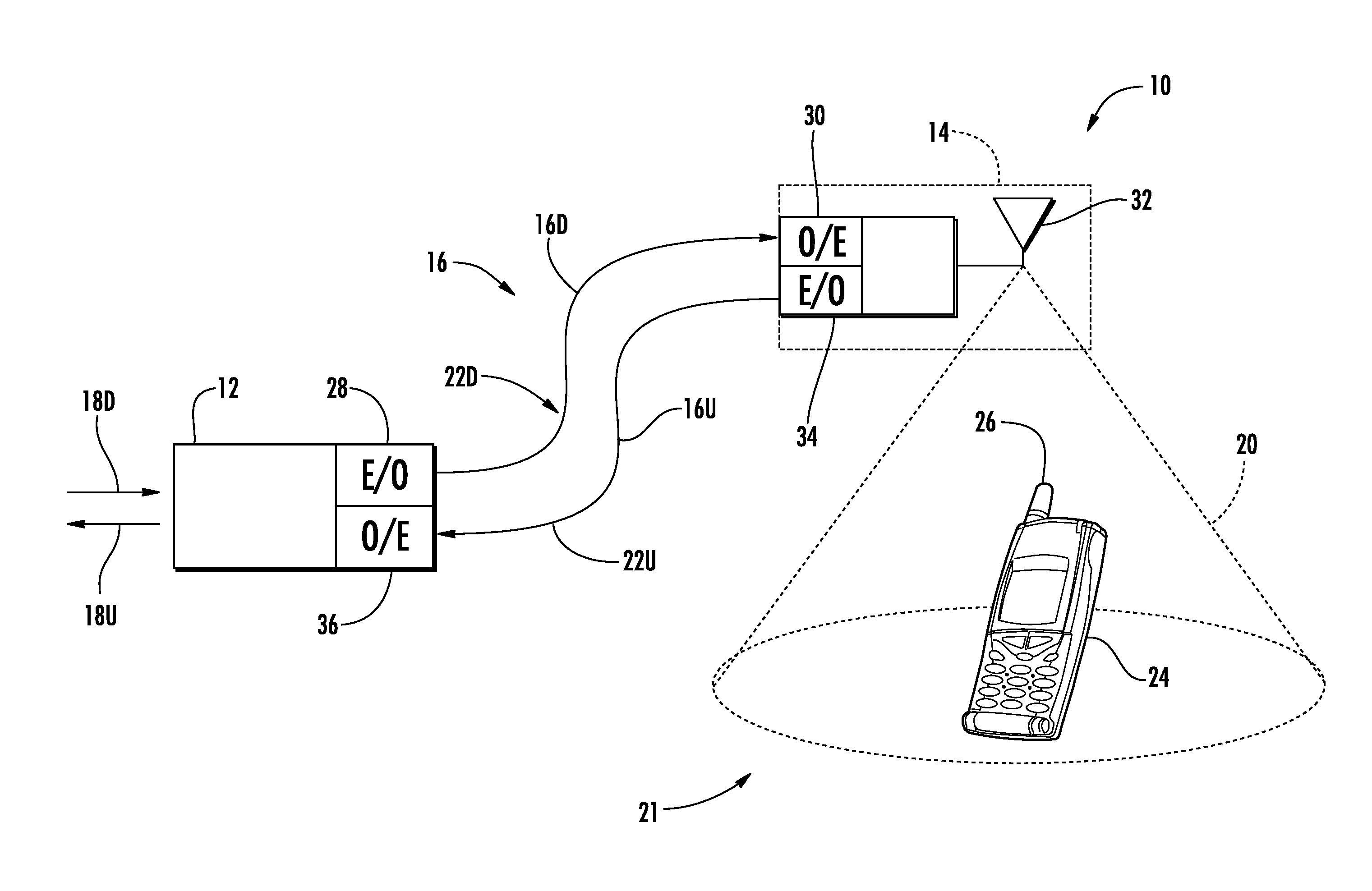
Wireless customers are demanding digital data services, such as streaming video signals. Concurrently, some wireless customers use their wireless devices in areas that are poorly served by conventional cellular networks, such as inside certain buildings or areas where there is little cellular coverage. One response to the intersection of these two concerns has been the use of distributed antenna systems. Distributed antenna systems can be particularly useful to be deployed inside buildings or other indoor environments where client devices may not otherwise be able to effectively receive radio-frequency (RF) signals from a source. Distributed antenna systems include remote units (also referred to as "remote antenna units") configured to receive and wirelessly transmit wireless communications signals to client devices in antenna range of the remote units. Such distributed antenna systems may use Wireless Fidelity (WiFi) or wireless local area networks (WLANs), as examples, to provide digital data services.
Distributed antenna systems may employ optical fiber to support distribution of high bandwidth data (e.g., video data) with low loss. Even so, WiFi and WLAN-based technology may not be able to provide sufficient bandwidth for expected demand, especially as HD video becomes more prevalent. WiFi was initially limited in data rate transfer to 12.24 Mb/s and is provided at data transfer rates of up to 54 Mb/s using WLAN frequencies of 2.4 GHz and 5.8 GHz. While interesting for many applications, WiFi bandwidth may be too small to support real time downloading of uncompressed HD television signals to wireless client devices.
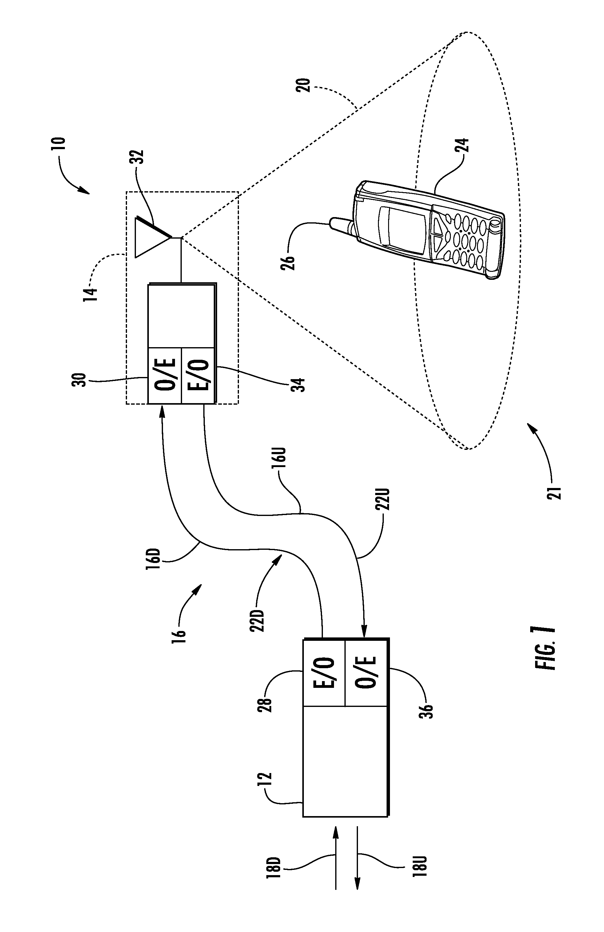
MIMO technology can be employed in distributed antenna systems to increase the bandwidth up to twice the nominal bandwidth, as a non-limiting example. MIMO is the use of multiple antennas at both a transmitter and receiver to increase data throughput and link range without additional bandwidth or increased transmit power. However, even doubling bandwidth alone may not be enough to support high bandwidth data to wireless client devices, such as the example of real time downloading of uncompressed high definition (HD) television signals.
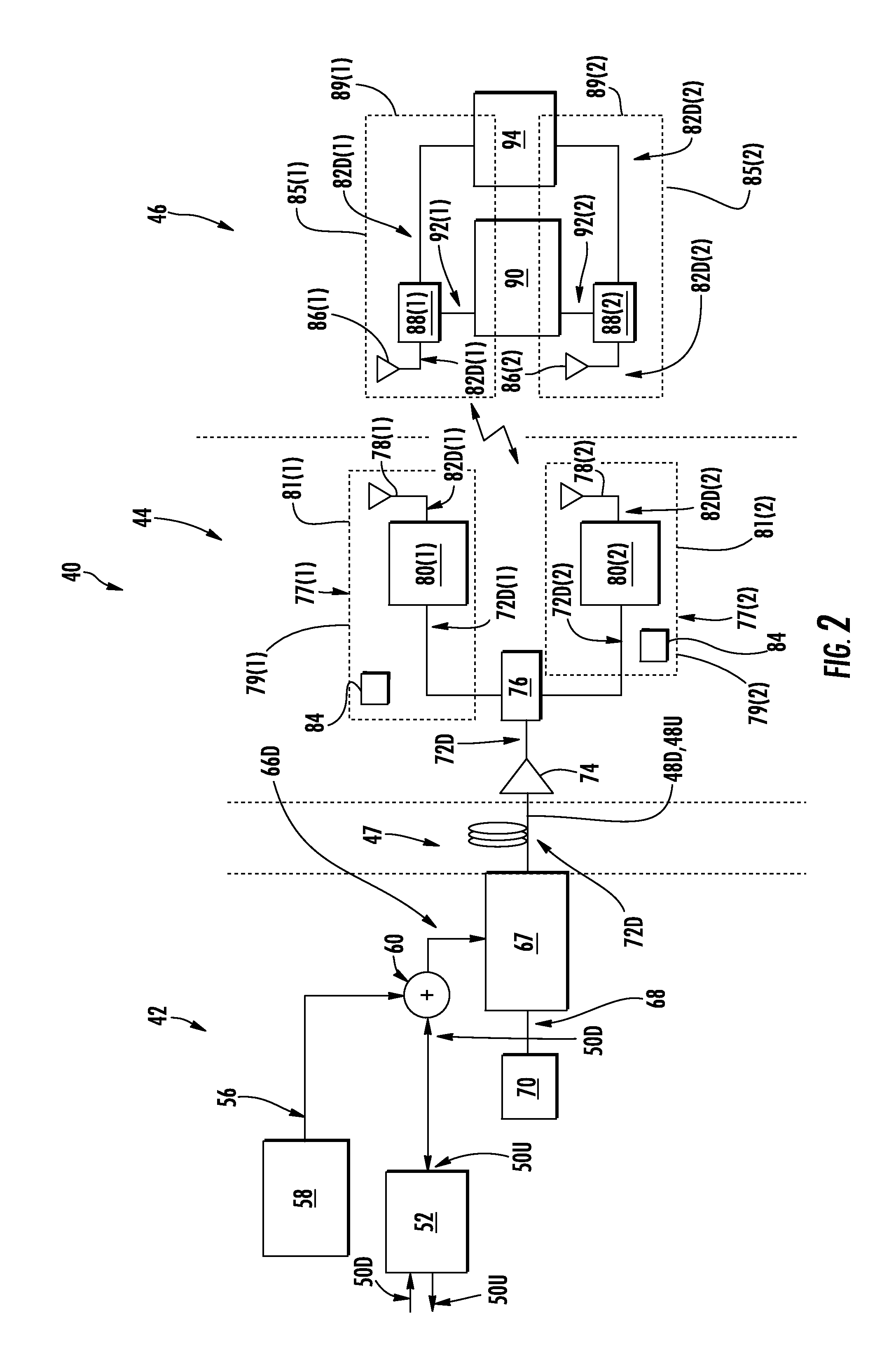
The frequency of wireless communications signals could also be increased in a MIMO distributed antenna system to provide larger channel bandwidth as a non-limiting example. For example, an extremely high frequency (EHF) in the range of approximately 30 GHz to approximately 300 GHz could be employed. For example, the sixty GHz (60 GHz) spectrum is an EHF that is an unlicensed spectrum by the Federal Communications Commission (FCC). EHFs could be employed to provide for larger channel bandwidths. However, higher frequency wireless signals are more easily attenuated and/or blocked from traveling through walls, building structures, or other obstacles where distributed antenna systems are commonly installed. Higher frequency wireless signals also provide narrow radiation patterns. Thus, remote units in distributed antenna systems may be arranged for line-of-sight (LOS) communications to allow for higher frequencies for higher bandwidth. However, if remote units are provided in a LOS configuration and the remote units are also configured to support MIMO, multiple spatial streams received by multiple receiver antennas in the remote units may be locked into a relative phase and/or amplitude pattern. This can lead to multiple received spatial streams periodically offsetting each other when the spatial streams are combined at MIMO receivers, leading to performance degradation and reduced wireless coverage.
No admission is made that any reference cited herein constitutes prior art. Applicant expressly reserves the right to challenge the accuracy and pertinency of any cited documents.
SUMMARY
Components, systems, and methods for reducing location-dependent destructive interference in distributed antenna systems (DASs) operating in multiple-input, multiple-output (MIMO) configuration are disclosed. The DASs include remote units employing MIMO transmitters configured to transmit multiple data streams in MIMO configuration to MIMO receivers in wireless client devices. Destructive interference in a MIMO system can occur when two or more spatial streams transmitted from multiple MIMO antennas are locked into a relative phase and/or amplitude pattern, causing periodic destructive interferences when the two or more spatial streams are combined at MIMO receivers in client devices. These issues can occur due to lack of separation (i.e., phase, amplitude) in the received MIMO communications signals, especially with closely located MIMO transmitters configured for line-of-sight (LOS) communications. Thus, to provide spatial separation of MIMO communications signals received by MIMO receivers in client devices, multiple MIMO transmitters in a remote unit in a DAS are each configured to employ multiple transmitter antennas, which are each configured to transmit in different polarization states. In certain embodiments, the amplitude of one of the MIMO communications signals is modified in one of the polarization states to further provide amplitude separation between the MIMO communications signals received by the MIMO receivers.
The components, systems, and methods for reducing location-dependent periodic destructive interference in distributed antenna systems operating in MIMO configuration may significantly improve high-data rate wireless coverage without significant dependence on transmitter and/or receive placement. This may allow for LOS communications to be more easily achieved between MIMO transmitters and MIMO receivers, especially for higher frequency communications where LOS communications may be required to reduce destructions to higher frequency signals by obstacles on the transmission path. High antenna isolation is not required in the MIMO receivers. No additional hardware component is required in the MIMO transmitters or receivers as well. The improved MIMO performance and increased coverage area can also allow higher frequency bands (e.g., 60 GHz) to be used efficiently to provide multi-gigabit per second (Gbps) data access to client devices in indoor and outdoor environments.
One embodiment of the disclosure relates to a MIMO remote unit configured to wirelessly distribute MIMO communications signals to wireless client devices in a distributed antenna system. The MIMO remote unit comprises a first MIMO transmitter comprising a first MIMO transmitter antenna configured to transmit MIMO communications signals in a first polarization and a second MIMO transmitter antenna configured to transmit MIMO communications signals in a second polarization different from the first polarization. The MIMO remote unit also comprises a second MIMO transmitter comprising a third MIMO transmitter antenna configured to transmit MIMO communications signals in the first polarization and a fourth MIMO transmitter antenna configured to transmit MIMO communications signals in the second polarization. The first MIMO transmitter is configured to receive a first downlink MIMO communications signal at a first amplitude over a first downlink communications medium, and transmit the first downlink MIMO communications signal wirelessly as a first electrical downlink MIMO communications signal over the first MIMO transmitter antenna in the first polarization. The first MIMO transmitter is also configured to receive a second downlink MIMO communications signal at the first amplitude over a second downlink communications medium, and transmit the second downlink MIMO communications signal wirelessly as a second electrical downlink MIMO communications signal over the second MIMO transmitter antenna in the second polarization. The second MIMO transmitter is configured to receive a third downlink MIMO communications signal at the first amplitude over a third downlink communications medium, and transmit the third downlink MIMO communications signal wirelessly as a third electrical downlink MIMO communications signal over the third MIMO transmitter antenna in the first polarization. The second MIMO transmitter is also configured to receive a fourth downlink MIMO communications signal over a fourth downlink communications medium, and transmit the fourth downlink MIMO communications signal at a second amplitude modified from the first amplitude, wirelessly as a fourth electrical downlink MIMO communications signal over the fourth MIMO transmitter antenna in the second polarization.
An additional embodiment of the disclosure relates to a method of transmitting MIMO communications signals to wireless client devices in a distributed antenna system is provided. The method includes receiving a first downlink MIMO communications signal at a first amplitude over a first downlink communications medium. The method also includes transmitting the first downlink MIMO communications signal wirelessly as a first electrical downlink MIMO communications signal over a first MIMO transmitter antenna in a first polarization. The method also includes receiving a second downlink MIMO communications signal at the first amplitude over a second downlink communications medium. The method also includes transmitting the second downlink MIMO communications signal wirelessly as a second electrical downlink MIMO communications signal over a second MIMO transmitter antenna in a second polarization. The method also includes receiving a third downlink MIMO communications signal at the first amplitude over a third downlink communications medium. The method also includes transmitting the third downlink MIMO communications signal wirelessly as a third electrical downlink MIMO communications signal over a third MIMO transmitter antenna in the first polarization. The method also includes receiving a fourth downlink MIMO communications signal over a fourth downlink communications medium. The method also includes transmitting the fourth downlink MIMO communications signal at a second amplitude modified from the first amplitude, wirelessly as a fourth electrical downlink MIMO communications signal over a fourth MIMO transmitter antenna in the second polarization.
An additional embodiment of the disclosure relates to a distributed antenna system for distributing MIMO communications signals to wireless client devices. The distributed antenna system comprises a central unit. The central unit comprises a central unit transmitter configured to receive a downlink communications signal. The central unit transmitter is also configured to transmit the received downlink communications signal as a first downlink MIMO communications signal over a first downlink communications medium, a second downlink MIMO communications signal over a second downlink communications medium, a third MIMO downlink communications signal over a third downlink communications medium, and a fourth downlink MIMO communications signal over a fourth downlink communications medium.
This distributed antenna system also comprises a remote unit. The remote unit comprises a first MIMO transmitter comprising a first MIMO transmitter antenna configured to transmit MIMO communications signals in a first polarization and a second MIMO transmitter antenna configured to transmit MIMO communications signals in a second polarization different from the first polarization. The remote unit also comprises a second MIMO transmitter comprising a third MIMO transmitter antenna configured to transmit MIMO communications signals in the first polarization and a fourth MIMO transmitter antenna configured to transmit MIMO communications signals in the second polarization. The first MIMO transmitter is configured to receive a first downlink MIMO communications signal at a first amplitude over a first downlink communications medium, and transmit the first downlink MIMO communications signal wirelessly as a first electrical downlink MIMO communications signal over the first MIMO transmitter antenna in the first polarization. The first MIMO transmitter is also configured to receive a second downlink MIMO communications signal at the first amplitude over a second downlink communications medium, and transmit the second downlink MIMO communications signal wirelessly as a second electrical downlink MIMO communications signal over the second MIMO transmitter antenna in the second polarization. The second MIMO transmitter is configured to receive a third downlink MIMO communications signal at the first amplitude over a third downlink communications medium, and transmit the third downlink MIMO communications signal wirelessly as a third electrical downlink MIMO communications signal over the third MIMO transmitter antenna in the first polarization. The second MIMO transmitter is also configured to receive a fourth downlink MIMO communications signal over a fourth downlink communications medium, and transmit the fourth downlink MIMO communications signal at a second amplitude modified from the first amplitude, wirelessly as a fourth electrical downlink MIMO communications signal over the fourth MIMO transmitter antenna in the second polarization. The remote unit also comprises at least one amplitude adjustment circuit configured to amplitude adjust the fourth downlink MIMO communications signal to the second amplitude.
The distributed antenna systems disclosed herein can be configured to support one or more radio-frequency (RF)-based services and/or distribution of one or more digital data services. The remote units in the distributed antenna systems may be configured to transmit and receive wireless communications signals at one or more frequencies, including but not limited to extremely high frequencies (EHF) (i.e., approximately 30 GHz--approximately 300 GHz). The distributed antenna systems may include, without limitation, wireless local area networks (WLANs). Further, as a non-limiting example, the distributed antenna systems may be an optical fiber-based distributed antenna system, but such is not required. An optical fiber-based distributed antenna system may employ Radio-over-Fiber (RoF) communications. The embodiments disclosed herein are also applicable to other remote antenna clusters and distributed antenna systems, including those that include other forms of communications media for distribution of communications signals, including electrical conductors and wireless transmission. For example, the distributed antenna systems may include electrical and/or wireless communications mediums between a central unit and remote units in addition or in lieu of optical fiber communications medium. The embodiments disclosed herein may also be applicable to remote antenna clusters and distributed antenna systems and may also include more than one communications media for distribution of communications signals (e.g., digital data services, RF communications services). The communications signals in the distributed antenna system may or may not be frequency shifted.
Additional features and advantages will be set forth in the detailed description which follows, and in part will be readily apparent to those skilled in the art from the description or recognized by practicing the embodiments as described in the written description and the claims hereof, as well as the appended drawings.
It is to be understood that both the foregoing general description and the following detailed description are merely exemplary, and are intended to provide an overview or framework to understand the nature and character of the claims. The accompanying drawings are included to provide a further understanding and are incorporated in and constitute a part of this specification. The drawings illustrate one or more embodiments, and together with the description serve to explain principles and operation of the various embodiments.
BRIEF DESCRIPTION OF THE DRAWINGS
FIG. 1 is a schematic of an exemplary distributed antenna system;
FIG. 2 is a schematic diagram of an exemplary multiple-input, multiple-output (MIMO) optical fiber-based distributed antenna system;
FIG. 3A is a top view diagram of a room having an exemplary MIMO antenna system comprising two (2) MIMO transmitter antennas in line-of-sight (LOS) with two (2) MIMO receiver antennas to illustrate periodic destructive interference in MIMO communications signals received in the same frequency channel by the MIMO receiver antennas;
FIG. 3B is a graph illustrating exemplary measured periodic performance degradations for a given placement distance between the MIMO transmitter antennas in the MIMO antenna system in FIG. 3A;
FIG. 3C is a graph illustrating an exemplary effective antenna coverage area in proximity to the MIMO transmitter antennas in FIG. 3A;
FIG. 4 is a schematic diagram of an exemplary amplitude adjustment circuit for amplitude adjusting a downlink (DL) MIMO communications signal transmitted by a MIMO transmitter antenna in FIG. 2;
FIG. 5 is a flowchart illustrating an exemplary amplitude adjustment process performed by the exemplary amplitude adjustment circuit in FIG. 4 for amplitude adjusting a downlink (DL) MIMO communications signal transmitted by a MIMO transmitter antenna in FIG. 2;
FIG. 6A is a schematic diagram of an exemplary MIMO optical fiber-based distributed antenna system employing a central unit employing a MIMO transmitter configured to electrically amplitude adjust at least one transmitted MIMO electrical downlink communications signal received and transmitted by a remote unit employing multiple MIMO transmitters each configured with multiple MIMO transmitter antennas configured to transmit in different polarization states;
FIG. 6B is a schematic diagram of an exemplary MIMO optical fiber-based distributed antenna system employing an amplitude adjustment circuit of FIG. 4 in an optical downlink communications medium configured to provide amplitude adjustment to at least one transmitted MIMO electrical downlink communications signal received and transmitted by a remote unit employing multiple MIMO transmitters each configured with multiple MIMO transmitter antennas configured to transmit in different polarization states;
FIG. 6C is a schematic diagram of an exemplary MIMO optical fiber-based distributed antenna system employing remote units employing multiple MIMO transmitters each employing multiple MIMO transmitter antennas configured to transmit in different polarization states, wherein one of the MIMO electrical downlink communications signals transmitted by one of the MIMO transmitters in a polarization state is electrically amplitude adjusted;
FIG. 7 is a schematic diagram illustrating exemplary implementation options of an amplitude adjustment circuit in FIG. 4 in a central unit in FIGS. 6A-6C;
FIG. 8A is a graph illustrating exemplary MIMO communications signal waveforms transmitted by a first MIMO transmitter antenna and a second MIMO transmitter antenna of a MIMO transmitter in a remote unit in FIGS. 6A-6C without amplitude adjustment;
FIG. 8B is a graph illustrating exemplary MIMO communications signal waveforms transmitted by a first MIMO transmitter antenna and a second MIMO transmitter antenna of a MIMO transmitter in a remote unit in FIGS. 6A-6C with amplitude adjustment;
FIG. 8C is a graph illustrating exemplary measured periodic performance degradation for a given placement distance between MIMO transmitter antennas in a MIMO transmitter in a remote unit in the distributed antenna system in FIGS. 6A-6C, when employing and not employing amplitude adjustment of at least one transmitted downlink communications signals;
FIG. 8D is a graph illustrating an exemplary effective antenna coverage versus placement distance between MIMO transmitter antennas in a MIMO transmitter in a remote unit in the distributed antenna system in FIGS. 6A-6C, for a given placement distance between MIMO receiver antennas, when employing and not employing amplitude adjustment of at least one transmitted downlink communications signal; and
FIG. 9 is a schematic diagram of a generalized representation of an exemplary controller that can be included in any central unit, remote units, wireless client devices, and/or any other components of distributed antenna systems to reduce or eliminate issues of periodic destructive interference in transmitted MIMO electrical downlink communications signals, wherein the exemplary computer system is adapted to execute instructions from an exemplary computer readable medium.
DETAILED DESCRIPTION
Components, systems, and methods for reducing location-dependent destructive interference in distributed antenna systems (DASs) operating in multiple-input, multiple-output (MIMO) configuration are disclosed. The DASs include remote units employing MIMO transmitters configured to transmit multiple data streams in MIMO configuration to MIMO receivers in wireless client devices. Destructive interference in a MIMO system can occur when two or more spatial streams transmitted from multiple MIMO antennas are locked into a relative phase and/or amplitude pattern, causing periodic destructive interferences when the two or more spatial streams are combined at MIMO receivers in client devices. These issues can occur due to lack of separation (i.e., phase, amplitude) in the received MIMO communications signals, especially with closely located MIMO transmitters configured for line-of-sight (LOS) communications. Thus, to provide spatial separation of MIMO communications signals received by MIMO receivers in client devices, multiple MIMO transmitters in a remote unit in a DAS are each configured to employ multiple transmitter antennas, which are each configured to transmit in different polarization states. In certain embodiments, the amplitude of one of the MIMO communications signals is modified in one of the polarization states to further provide amplitude separation between the MIMO communications signals received by the MIMO receivers. Various embodiments will be explained by the following examples.
Before discussing examples of components, systems, and methods for reducing location-dependent destructive interference in distributed antenna systems operating in MIMO configuration starting at FIG. 4, an exemplary distributed antenna system is described in regard to FIGS. 1-3C. In this regard, FIG. 1 is a schematic diagram of a conventional distributed antenna system 10. The distributed antenna system 10 is an optical fiber-based distributed antenna system. The distributed antenna system 10 is configured to create one or more antenna coverage areas for establishing communications with wireless client devices located in the radio frequency (RF) range of the antenna coverage areas. In an exemplary embodiment, the distributed antenna system 10 may provide RF communication services (e.g., cellular services). As illustrated, the distributed antenna system 10 includes a central unit 12, one or more remote units 14, and an optical fiber 16 that optically couples the central unit 12 to the remote unit 14. The central unit 12 may also be referred to as a head-end unit. The remote unit 14 is a type of remote communications unit, and may also be referred to as a "remote antenna unit." In general, a remote communications unit can support wireless communications or wired communications, or both. The central unit 12 is configured to receive communications over downlink electrical RF signals 18D from a source or sources, such as a network or carrier as examples, and provide such communications to the remote unit 14. The central unit 12 is also configured to return communications received from the remote unit 14, via uplink electrical RF signals 18U, back to the source or sources. In this regard, in this embodiment, the optical fiber 16 includes at least one downlink optical fiber 16D to carry signals communicated from the central unit 12 to the remote unit 14 and at least one uplink optical fiber 16U to carry signals communicated from the remote unit 14 back to the central unit 12.
One downlink optical fiber 16D and one uplink optical fiber 16U could be provided to support multiple full-duplex channels each using wave-division multiplexing (WDM), as discussed in U.S. patent application Ser. No. 12/892,424, entitled "Providing Digital Data Services in Optical Fiber-based Distributed Radio Frequency (RF) Communications Systems, And Related Components and Methods," incorporated herein by reference in its entirety. Other options for WDM and frequency-division multiplexing (FDM) are also disclosed in U.S. patent application Ser. No. 12/892,424, any of which can be employed in any of the embodiments disclosed herein. Further, U.S. patent application Ser. No. 12/892,424 also discloses distributed digital data communications signals in a distributed antenna system which may also be distributed in the distributed antenna system 10 either in conjunction with the RF communications signals or not.
The distributed antenna system 10 has an antenna coverage area 20 that can be disposed around the remote unit 14. The antenna coverage area 20 of the remote unit 14 forms an RF coverage area 21. The central unit 12 is adapted to perform or to facilitate any one of a number of Radio-over-Fiber (RoF) applications, such as RF identification (RFID), wireless local-area network (WLAN) communication, or cellular phone service. Shown within the antenna coverage area 20 is a client device 24 in the form of a mobile device, which may be a cellular telephone as an example. The client device 24 can be any device that is capable of receiving RF communications signals. The client device 24 includes an antenna 26 (e.g., a wireless card) adapted to receive and/or send electromagnetic RF signals.
With continuing reference to FIG. 1, to communicate the electrical RF signals over the downlink optical fiber 16D to the remote unit 14, to in turn be communicated to the client device 24 in the antenna coverage area 20 formed by the remote unit 14, the central unit 12 includes a radio interface in the form of an electrical-to-optical (E/O) converter 28. The E/O converter 28 converts the downlink electrical RF signals 18D to downlink optical RF signals 22D to be communicated over the downlink optical fiber 16D. The remote unit 14 includes an optical-to-electrical (O/E) converter 30 to convert the received downlink optical RF signals 22D back to electrical RF signals to be communicated wirelessly through an antenna 32 of the remote unit 14 to the client device 24 located in the antenna coverage area 20.
Similarly, the antenna 32 is also configured to receive wireless RF communications from the client device 24 in the antenna coverage area 20. In this regard, the antenna 32 receives wireless RF communications from the client device 24 and communicates electrical RF signals representing the wireless RF communications to an E/O converter 34 in the remote unit 14. The E/O converter 34 converts the electrical RF signals into uplink optical RF signals 22U to be communicated over the uplink optical fiber 16U. An 0/E converter 36 provided in the central unit 12 converts the uplink optical RF signals 22U into uplink electrical RF signals, which can then be communicated as uplink electrical RF signals 18U back to a network or other source.
As noted, one or more of the network or other sources can be a cellular system, which may include a base station or base transceiver station (BTS). The BTS may be provided by a second party such as a cellular service provider, and can be co-located or located remotely from the central unit 12.
In a typical cellular system, for example, a plurality of BTSs is deployed at a plurality of remote locations to provide wireless telephone coverage. Each BTS serves a corresponding cell and when a mobile client device enters the cell, the BTS communicates with the mobile client device. Each BTS can include at least one radio transceiver for enabling communication with one or more subscriber units operating within the associated cell. As another example, wireless repeaters or bi-directional amplifiers could also be used to serve a corresponding cell in lieu of a BTS. Alternatively, radio input could be provided by a repeater, picocell, or femtocell, as other examples. In a particular exemplary embodiment, cellular signal distribution in the frequency range from 400 MHz to 2.7 GHz is supported by the distributed antenna system 10.
Although the distributed antenna system 10 in FIG. 1 allows for distribution of radio frequency (RF) communications signals; the distributed antenna system 10 is not limited to distribution of RF communications signals. Data communications signals, including digital data signals, for distributing data services could also be distributed in the distributed antenna system 10 in lieu of or in addition to RF communications signals. Also note that while the distributed antenna system 10 in FIG. 1 discussed below includes distribution of communications signals over optical fiber, the distributed antenna system 10 is not limited to distribution of communications signals over optical fiber. Distribution media could also include, but are not limited to, coaxial cable, twisted-pair conductors, wireless transmission and reception, and any combination thereof. Also, any combination can be employed that also involves optical fiber for portions of the distributed system.
A distributed antenna system, including the distributed antenna system 10 in FIG. 1, can be configured in MIMO configuration for MIMO operation. In this regard, FIG. 2 illustrates a schematic diagram of an exemplary MIMO optical fiber-based distributed antenna system 40 (hereinafter referred to as "MIMO distributed antenna system 40"). The MIMO distributed antenna system 40 is configured to operate in MIMO configuration. MIMO technology involves the use of multiple antennas at both a transmitter and receiver to improve communication performance. In this regard, a central unit 42 is provided that is configured to distribute downlink communications signals to one or more remote units 44. FIG. 2 only illustrates one remote unit 44, but note that a plurality of remote units 44 is typically provided. The remote units 44 are configured to wirelessly communicate the downlink communication signals to one or more client devices 46 that are in communication range of the remote unit 44. The remote units 44 may also be referred to as "remote antenna units 44" because of their wireless transmission over antenna functionality. The remote unit 44 is also configured to receive uplink communication signals from the client devices 46 to be distributed to the central unit 42. In this embodiment, an optical fiber communications medium 47 comprising at least one downlink optical fiber 48D and at least one uplink optical fiber 48U is provided to commutatively couple the central unit 42 to the remote units 44. The central unit 42 is also configured to receive uplink communication signals from the remote units 44 via the optical fiber communications medium 47, although more specifically over the at least one uplink optical fiber 48U. The client device 46 in communication with the remote unit 44 can provide uplink communication signals to the remote unit 44 which are then distributed over the optical fiber communications medium 47 to the remote unit 44 to be provided to a network or other source, such as a base station for example.
With continuing reference to FIG. 2, more detail will be discussed regarding the components of the central unit 42, the remote unit 44, and the client device 46 and the distribution of downlink communications signals. The central unit 42 is configured to receive electrical downlink MIMO communication signals 50D from outside the MIMO distributed antenna system 40 in a signal processor 52 and provide electrical uplink communications signals 50U received from client devices 46, to other systems. The signal processor 52 is configured to provide the electrical downlink communication signals 50D to a mixer 60, which may be an IQ signal mixer in this example. The mixer 60 in this embodiment is configured to convert the electrical downlink MIMO communication signals 50D to IQ signals. The mixer 60 is driven by a frequency signal 56 that is provided by a local oscillator 58. Frequency conversion is optional. In this embodiment, it is desired to up-convert the frequency of the electrical downlink MIMO communication signals 50D to a higher frequency to provide electrical downlink MIMO communication signals 66D to provide for a greater bandwidth capability before distributing the electrical downlink MIMO communications signals 66D to the remote units 44. For example, the up-conversion carrier frequency may be provided as an extremely high frequency (e.g. approximately 30 GHz to 300 GHz).
With continuing reference to FIG. 2, because the communication medium between the central unit 42 and the remote unit 44 is the optical fiber communications medium 47, the electrical downlink MIMO communication signals 66D are converted to optical signals by an electro-optical converter 67. The electro-optical converter 67 includes components to receive a light wave 68 from a light source 70, such as a laser. The light wave 68 is modulated by the frequency oscillations in the electrical downlink MIMO communication signals 66D to provide optical downlink MIMO communication signals 72D to be communicated over the downlink optical fiber 48D to the remote unit 44. The electro-optical converter 67 may be provided so that the electrical downlink MIMO communication signals 66D are provided as radio-over-fiber (RoF) communications signals over the downlink optical fiber 48D.
With continuing reference to FIG. 2, the optical downlink MIMO communication signals 72D are received by an optical bi-directional amplifier 74, which is then provided to a MIMO splitter 76 in the remote unit 44. The MIMO splitter 76 is provided so that the optical downlink MIMO communication signals 72D can be split among two separate communication paths 77(1), 77(2) to be radiated over two separate MIMO transmitter antennas 78(1), 78(2) provided in two separate MIMO transmitters 79(1), 79(2) configured in MIMO configuration. The MIMO splitter 76 in the remote unit 44 is an optical splitter since the received optical downlink MIMO communication signals 72D are optical signals. In each communication path 77(1), 77(2), optical-to-electrical converters 80(1), 80(2) are provided to convert the optical downlink MIMO communication signals 72D to electrical downlink MIMO communication signals 82D(1), 82D(2). In this embodiment, as will be discussed in more detail below, an amplitude adjustment circuit 84 is provided in one of the transmission paths 77(1), 77(2) to provide amplitude adjustment in one of the optical downlink MIMO communication signals 72D(1), 72D(2) transmitted over one of the MIMO transmitter antennas 78(1), 78(2) to help reduce or eliminate periodic destructive interferences when received electrical downlink MIMO communication signals 82D are combined at the client device 46.
A destructive interference occurs when the electrical downlink MIMO communication signals 82D(1), 82D(2) are locked into a relative phase and/or amplitude pattern, causing them to cancel each other when combined at MIMO receivers 85(1), 85(2). Because the electrical downlink MIMO communication signals 82D(1), 82D(2) are periodic radio frequency waves, the destructive interference also becomes periodic as result. When physical obstacles (e.g., buildings, walls, trees, vehicles, etc.) standing in radio transmission paths between the MIMO transmitter antennas 78(1), 78(2) and the MIMO receiver antennas 86(1), 86(2), the electrical downlink MIMO communication signals 82D(1), 82D(2) transmitted by the MIMO transmitter antennas 78(1), 78(2) typically arrive at the MIMO receiver antennas 86(1), 86(2) from different directions and/or angles (also known as "multipath") due to reflections from the physical obstacles. Due to multipath effect, the electrical downlink MIMO communication signals 82D(1), 82D(2) transmitted by the MIMO transmitter antennas 78(1), 78(2) may arrive at the MIMO receiver antennas 86(1), 86(2) with slight delays among each other, resulting in natural phase shifts between the electrical downlink MIMO communication signals 82D(1), 82D(2). Further, the amplitudes of the electrical downlink MIMO communication signals 82D(1), 82D(2) may also be modified due to different reflection angles caused by different obstacles along different transmission paths. In this regard, multipath acts to break up the locked-in phase and/or amplitude pattern among the electrical downlink MIMO communication signals 82D(1), 82D(2) transmitted by the MIMO transmitter antennas 78(1), 78(2) and, thus, helps mitigate periodic destructive interferences at MIMO receivers 85(1), 85(2). However, when a millimeter wave radio frequency band (e.g., 60 GHz) is employed as the carrier frequency between the MIMO transmitter antennas 78(1), 78(2) and the MIMO receiver antennas 86(1), 86(2), there cannot be any physical obstacle stand in the radio transmission path. This is because higher frequency signals like a 60 GHz signal are inherently incapable of penetrating or bouncing off physical obstacles. To prevent millimeter wave radio frequency signals from being blocked by physical obstacles, the MIMO transmitter antennas 78(1), 78(2) and the MIMO receiver antennas 86(1), 86(2) must be configured in a line-of-sight (LOS) arrangement, which is further elaborated in FIGS. 3A-3C. With the LOS arrangement, multipath becomes non-existent between the MIMO transmitter antennas 78(1), 78(2) and the MIMO receiver antennas 86(1), 86(2). Therefore, periodic destructive interferences often occur when the electrical downlink MIMO communication signals 82D(1), 82D(2) are combined at the MIMO receivers 85(1), 85(2).
With continuing reference to FIG. 2, the client device 46 includes two MIMO receivers 85(1), 85(2) that include MIMO receiver antennas 86(1), 86(2) also configured in MIMO configuration. The MIMO receiver antennas 86(1), 86(2) are configured to receive the electrical downlink MIMO communication signals 82D(1), 82D(2) wirelessly from the remote unit 44. Mixers 88(1), 88(2) are provided and coupled to the MIMO receiver antennas 86(1), 86(2) in the client device 46 to provide frequency conversion of the electrical downlink MIMO communication signals 82D(1), 82D(2). In this regard, a local oscillator 90 is provided that is configured to provide oscillation signals 92(1), 92(2) to the mixers 88(1), 88(2), respectively, for frequency conversion. In this embodiment, the electrical downlink MIMO communications signals 82D(1), 82D(2) are down converted back to their native frequency as received by the central unit 42. The down converted electrical downlink MIMO communication signals 82D(1), 82D(2) are then provided to a signal analyzer 94 in the client device 46 for any processing desired.
FIG. 3A illustrates a top view of a room 100 employing the exemplary MIMO distributed antenna system 40 in FIG. 2 to discuss performance of MIMO communications as affected by antenna placement. As illustrated in FIG. 3A, the two MIMO transmitter antennas 78(1), 78(2) of the remote unit 44 are shown as being located in the room 100. Similarly, a client device 46 is shown with its two MIMO receiver antennas 86(1), 86(2) configured to receive the electrical downlink MIMO communication signals 82D(1), 82D(2) from the two MIMO transmitters 81(1), 81(2) (shown in FIG. 2) in MIMO configuration. The two MIMO transmitter antennas 78(1), 78(2) and two MIMO receiver antennas 86(1), 86(2) are placed according to the LOS arrangement. The LOS arrangement ensures that the electrical downlink MIMO communication signals 82D(1), 82D(2) from the two MIMO transmitters 81(1), 81(2) are directed towards the two MIMO receiver antennas 86(1), 86(2), even if the electrical downlink MIMO communication signals 82D(1), 82D(2) are reflected on the downlink propagation path. In other words, the LOS arrangement does not stop the two MIMO receiver antennas 86(1), 86(2) from receiving reflected signals. The MIMO transmitter antennas 78(1), 78(2) in the MIMO transmitters 81(1), 81(2) in the remote unit 44 are separated by a distance D.sub.1. The MIMO receiver antennas 86(1), 86(2) in the client device 46 are separated by a distance D.sub.2. In absence of multipath due to the LOS arrangement, issues can arise, due to destructive interference, with MIMO algorithm being able to solve the channel matrix for received electrical downlink MIMO communication signals 82D(1), 82D(2) at the client device 46 as a function of the distance D.sub.1 between the MIMO transmitter antennas 78(1), 78(2) in the remote unit 44, the distance D.sub.2 between MIMO receiver antennas 86(1), 86(2) in the client device 46, and the distance D.sub.3 between remote unit 44 and the client device 46. These issues are also referred to herein as location-dependent destructive interference issues.
Location-dependent destructive interference for the received electrical downlink MIMO communication signals 82D(1), 82D(2) can negatively affect MIMO communications performance. These issues with electrical downlink MIMO communication signals 82D(1), 82D(2) received by the MIMO receiver antennas 86(1), 86(2) can occur due to lack of separation (e.g., phase, amplitude) in the received electrical downlink MIMO communication signals 82D(1), 82D(2), especially in LOS communications. To illustrate the effect of these issues, FIG. 3B illustrates a graph 102 illustrating the exemplary measured performance degradation for a given placement distance between the MIMO transmitter antennas 78(1), 78(2) in FIG. 3A. The graph 102 in FIG. 3B illustrates the capacity on the y-axis in Gigabits per second (Gbps) versus the MIMO transmitter antennas 78(1), 78(2) separation distance D.sub.1 in centimeters. As illustrated in the graph 102, at separation distances D.sub.1 of approximately 42 centimeters (cm) and 85 cm, the communications capacity illustrated by a capacity curve 104 is periodically degraded due to periodic destructive interferences between the received electrical downlink MIMO communication signals 82D(1), 82D(2). Similarly, a MIMO condition number curve 106 in FIG. 3B also illustrates the effect periodic destructive interferences between the received electrical downlink MIMO communication signals 82D(1), 82D(2), which is complementary to the capacity curve 104.
FIG. 3C illustrates a graph 108 representing an exemplary effective communication coverage area provided by the MIMO distributed antenna system 40 in FIG. 2 according to the MIMO transmitter antennas 78(1), 78(2), separation distance D.sub.1, the MIMO receiver antennas 86(1), 86(2), separation distance D.sub.2 in FIG. 3A, and distance D.sub.3 therebetween. As illustrated in FIG. 3C, a desired antenna coverage area 109 is shown as being provided by the area formed inside a boundary line 110. However, an actual communication coverage area 113 for the remote unit 44 is provided inside the boundary line 112, illustrating the effect in reduction communication range of the remote unit 44.
To address these issues, FIGS. 4-8D are provided to illustrate exemplary distributed antenna systems configured to reduce location-dependent destructive interference in distributed antenna systems operating in MIMO configuration. In these embodiments, to provide spatial separation of MIMO communication signals received by MIMO receivers in client devices, multiple MIMO transmitters in a remote unit are each configured to employ multiple transmitter antennas. The multiple transmitter antennas are each configured to transmit communications signals in different polarization states. In certain embodiments, one of the MIMO communications signals is amplitude adjusted in one of the polarization states to provide amplitude separation between MIMO communication signals received by the MIMO receivers.
In this regard, FIG. 4 illustrates an exemplary amplitude adjustment circuit for amplitude adjusting a DL MIMO communication signal transmitted by a MIMO transmitter antenna 78 in FIG. 2. The exemplary amplitude adjustment circuit 120 comprises a signal controller 122 and an amplitude adjustment logic 124. As a non-limiting example, the amplitude adjustment logic 124 may be implemented by a hardware component, a software function, or a combination of both. In another non-limiting example, the signal controller 122 may be a digital baseband processor, a digital signal processor, a MIMO controller, or a general-purpose processor (e.g., central processing unit (CPU)). The signal controller 122 receives a MIMO performance measurement 126 on an uplink reception path (not shown). The signal controller 122 is configured to compare the MIMO performance measurement 126 with a pre-determined MIMO performance threshold. If the MIMO performance measurement 126 indicates a MIMO performance level is below the pre-determined MIMO performance threshold, the signal controller 122 is further configured to provide an amplitude adjustment signal 128 to the amplitude adjustment logic 124 to perform amplitude adjustment on a downlink MIMO communication signal 130. The amplitude adjustment logic 124 in turn performs amplitude adjustment on the downlink communication signal 130 received from a downlink transmission path (not shown). The amplitude adjustment circuit thus produces an amplitude-adjusted downlink communication signal 134 that is sent to a MIMO transmitter antenna on the downlink transmission path (not shown). In a non-limiting example, if the DL MIMO communication signal 130 has an original amplitude x, the amplitude adjustment logic 124 may produce a modified amplitude y that is different from the original amplitude x for the amplitude-adjusted downlink communication signal 134.
With continuing reference to FIG. 4, FIG. 5 illustrates an exemplary amplitude adjustment process performed by the exemplary amplitude adjustment circuit in FIG. 4. FIGS. 2 and 4 are referenced in connection with FIG. 5 and will not be re-described herein. The amplitude adjustment process 140 is invoked when wireless communication starts (block 142). The signal controller 122 receives and processes a MIMO performance measurement (block 144) and compares the MIMO performance measurement with a pre-determined threshold (block 146). If the MIMO performance measurement is above the pre-determined threshold, it indicates that the MIMO transmitter antennas 78 are performing as expected. In this case, the signal controller 122 will not take any action and awaits a next MIMO performance measurement. If, however, the MIMO performance measurement is below the pre-determined threshold, it is an indication that the MIMO transmitter antennas 78 are not performing as expected. Under such circumstance, the signal controller 122 will instruct the amplitude adjustment logic 124 to modify the amplitude of the downlink MIMO communication signal 130 (block 148). The amplitude adjustment process 140 repeats the step of comparing MIMO performance measurement against the pre-determined threshold (block 146) and the step of amplitude adjustment (block 148) until the next MIMO performance measurement is above the pre-determined threshold.
In this regard, FIGS. 6A-6C illustrate alternative MIMO distributed antenna systems 40(1)-40(3) similar to the MIMO distributed antenna system 40 in FIG. 2. FIGS. 6A-6C respectively illustrate three (3) different downlink signal processing stages in the MIMO distributed antenna systems 40(1)-40(3) wherein the amplitude adjustment circuit 120 may be provided. The MIMO distributed antenna systems 40(1)-40(3) in FIGS. 6A-6C are configured to reduce or eliminate periodic destructive interferences between received downlink communication signals at a MIMO receiver in a client device so as to reduce or eliminate performance degradation such as shown in FIGS. 3B and 3C above. The MIMO distributed antenna systems 40(1)-40(3) may include the same components in the MIMO distributed antenna system 40 in FIG. 2 unless otherwise noted in FIGS. 6A-6C. Elements of FIG. 4 are referenced in connection with FIGS. 6A-6C and will not be re-described herein.
With reference to FIG. 6A, a central unit 42(1) is configured to receive the electrical downlink MIMO communications signals 50D as discussed in regard to FIG. 2. However, a signal processor 52(1) is configured to split the electrical downlink MIMO communications signals 50D into four (4) electrical downlink MIMO communications signals 50D(1)-50D(4) over four separate channels. As a first option, an amplitude adjustment circuit 120(1) is provided in the central unit 42(1) to amplitude adjust at least one of the electrical downlink MIMO communications signals 50D. Note that although the electrical downlink MIMO communications signal 50D(4) is amplitude adjusted in this example, any other(s) downlink MIMO communications signal(s) 50D(1)-50D(3) could be amplitude adjusted as well. The amplitude adjustment circuit 120(1) may be programmed or controlled by the signal controller 122 to provide a pre-determined level of amplitude adjustment, if desired. Turning back to the central unit 42(1), electro-optical converters 67(1)-67(4) are provided to convert the electrical downlink MIMO communications signals 50D(1)-50D(4) into optical downlink MIMO communications signals 72D(1)-72D(4) provided over optical fiber communications medium 47(1).
With continuing reference to FIG. 6A, the remote unit 44(1) includes two MIMO transmitters 154(1), 154(2) in MIMO configuration. However, the MIMO transmitters 154(1), 154(2) each include two MIMO transmitter antennas 156(1)(1), 156(1)(2), and 156(2)(1), 156(2)(2). The first MIMO transmitter 154(1) includes the first MIMO transmitter antenna 156(1)(1) configured to radiate the first electrical downlink MIMO communications signals 82D(1) (after conversion from optical to electrical signals) in a first polarization 158(1). The first MIMO transmitter 154(1) also includes the second MIMO transmitter antenna 156(1)(2) configured to radiate the second electrical downlink MIMO communications signal 82D(2) in a second polarization 158(2) different from the first polarization 158(1). In this manner, the first and second electrical downlink MIMO communications signals 82D(1), 82D(2) can be received by two different MIMO receiver antennas 160(1), 160(2) in MIMO receivers 162(1), 162(2), respectively, each configured to receive signals in different polarizations 158(1), 158(2) among the first and second polarizations 158(1), 158(2) without experiencing periodic destructive interferences. Thus, the MIMO receivers 162(1), 162(2) can receive the first and second electrical downlink MIMO communications signal 82D(1), 82D(2) in different polarizations 158(1), 158(2), respectively, from the first MIMO transmitter 154(1) so that a MIMO algorithm can solve the channel matrix for the first and second electrical downlink MIMO communications signal 82D(1), 82D(2). In this embodiment, the first polarization 158(1) is configured to be orthogonal to the second polarization 158(2) to maximize spectral efficiency and minimize cross talk between the electrical downlink MIMO communications signals 82D(1), 82D(2) at the MIMO receivers 162(1), 162(2), but this configuration is not required.
With continuing reference to FIG. 6A, the second MIMO transmitter 154(2) in the remote unit 44(1) includes a third MIMO transmitter antenna 156(2)(1) configured to radiate the third electrical downlink MIMO communications signals 82D(3) (after conversion from optical to electrical signals) in the first polarization 158(1). The second MIMO transmitter 154(2) also includes the fourth MIMO transmitter antenna 156(2)(2) configured to radiate the fourth electrical downlink MIMO communications signal 82D(4) in the second polarization 158(2) different from the first polarization 158(1). In this manner, the third and fourth electrical downlink MIMO communications signals 82D(3), 82D(4) can also be received by the two different MIMO receiver antennas 160(1), 160(2) in MIMO receivers 162(1), 162(2), respectively, each configured to receive signals in different polarizations 158(1), 158(2) among the first and second polarizations 158(1), 158(2). Thus, the MIMO receivers 162(1), 162(2) can receive the third and fourth electrical downlink MIMO communications signal 82D(3), 82D(4) in different polarizations, respectively, from the second MIMO transmitter 154(2) between the third and fourth electrical downlink MIMO communications signal 82D(3), 82D(4). The electrical downlink MIMO communications signals 82D(1)-82D(4) are received by the MIMO receivers 162(1), 162(2) and provided to a signal processor 164 and a MIMO processor 166 for processing.
As previously discussed above, the amplitude adjustment circuit 120(1) is provided in the central unit 42(1) to amplitude adjust the electrical downlink MIMO communications signal 50D(4) The amplitude adjustment in the above example in turn causes the second and fourth electrical downlink MIMO communications signals 82D(2), 82D(4) to be received by the second MIMO receiver antennas 160(2) to have a small but sufficient amplitude difference. Further, the second and fourth electrical downlink MIMO communications signals 82D(2), 82D(4) are also received by the second MIMO receiver antenna 160(2) in the second polarization 158(2), which is different from the first and third electrical downlink MIMO communications signals 82D(1), 82D(3) received by the first MIMO receiver 162(1) in the first polarization 158(1). This combination of amplitude adjustment and MIMO transmitter antenna polarization can reduce or eliminate periodic destructive interferences between the first and the third electrical downlink MIMO communications signals 82D(1), 82D(3) being received by the first MIMO receiver 162(1) and between the second and the fourth electrical downlink MIMO communications signals 82D(2), 82D(4) being received by the second MIMO receiver 162(2).
As previously stated above, the amplitude adjustment circuit 120 can be provided in other downlink signal processing stages of the MIMO distributed antenna system 40 other than in the central unit, as provided in the MIMO distributed antenna system 40(1) in FIG. 6A. In this regard, FIG. 6B is a schematic diagram of another MIMO optical fiber-based distributed antenna system 40(2) ("MIMO distributed antenna system 40(2)") employing an amplitude adjustment circuit 120(2) in the optical fiber communications medium 47(1). The amplitude adjustment circuit 120(2) can be tunable to allow for the amplitude adjustment to be controlled and tuned. The amplitude adjustment circuit 120(2) may be an optical attenuator or amplifier that makes the amplitude of the optical downlink MIMO communications signal 72D(1) smaller or larger, respectively, than the other downlink optical fibers of the optical fiber communications medium 47(1). Common elements between the MIMO distributed antenna system 40(1) in FIG. 6A and the MIMO distributed antenna system 40(2) in FIG. 6B are noted with common element numbers and will not be re-described. In this embodiment, the amplitude adjustment circuit 120(2) is configured to optically amplitude adjust the optical downlink MIMO communications signal 72D(4) received and transmitted by the second MIMO transmitter 154(2) to the client device 46(1). The central unit 42(2) in FIG. 6B does not include the amplitude adjustment circuit 120(1) to amplitude shift downlink electrical communications signals like provided in the central unit 42(1) in FIG. 6A.
As previously discussed above with regard to FIGS. 6A and 6B, the amplitude adjustment circuit 120 can be provided in the central unit 42(1) and/or the optical fiber communications medium 47(1) to amplitude adjust the electrical downlink MIMO communications signal 50D(4). In this regard, FIG. 6C is a schematic diagram of another MIMO optical fiber-based distributed antenna system 40(3) ("MIMO distributed antenna system 40(3)") employing an amplitude adjustment circuit 120(3) in the form of an antenna power attenuator or amplifier in the remote unit 44(2). Common elements between the MIMO distributed antenna system 40(3) in FIG. 6C and the MIMO distributed antenna systems 40(1), 40(2) in FIGS. 6A and 6B are noted with common element numbers and will not be re-described. In this embodiment, a signal processor 174 in the remote unit 44(2) receives the optical downlink MIMO communications signals 72D(1)-72D(4) and converts these signals into electrical downlink MIMO communications signals 82D(1)-82D(4) in an optical-to-electrical converter. The amplitude adjustment circuit 120(3) is configured to electrically amplitude adjust the electrical downlink MIMO communications signal 82D(4) received and transmitted by the second MIMO transmitter 154(2) in the remote unit 44(2) to the client device 46(1) so that periodic destructive interferences resulting from LOS arrangement can be reduced or eliminated at the MIMO receivers 162(1), 162(2).
With reference back to FIG. 4, the amplitude adjustment circuit 120 includes the amplitude adjustment logic 124 configured to make amplitude adjustment on the DL MIMO communication signal 130 based on the amplitude adjustment signal 128 received from the signal controller 122. Also with reference back to FIG. 6A, the amplitude adjustment circuit 120(1) is provided in the central unit 42(1) of the MIMO distributed antenna system 40(1) to electronically amplitude adjust at least one of the electrical downlink MIMO communications signals 50D(4). The amplitude adjustment circuit 120(1) may be configured to provide amplitude adjustment in a plurality of ways depending on how the amplitude adjustment logic 124 is implemented. In this regard, FIG. 7 illustrates exemplary implementation options of the amplitude adjustment circuit 120(1) in the central unit 42(1). Elements of FIGS. 4 and 6A are referenced in connection with FIG. 7 and will not be re-described herein. Common elements between the central unit 42(1) in FIG. 6A and the central unit 42(3) in FIG. 7 are noted with common element numbers and will not be re-described.
With reference to FIG. 7, an amplitude adjustment circuit 120(4) in the central unit 42(3) may be implemented in three different options 120(4)(1), 120(4)(2), and 120(4)(3). An amplitude adjustment option 120(4)(1) comprises a signal controller 122(1) configured to receive a control signal 170(1) from a baseband signal processing module (not shown) and provide an amplitude adjustment signal 128(1) to an amplitude adjustment logic 124(1). In response to receiving the amplitude adjustment signal 128(1), the amplitude adjustment logic 124(1) performs amplitude adjustment on a downlink MIMO communications signal 50D(4) received from a signal processor 52(1). The amplitude adjustment logic 124(1), in this non-limiting example, is a tunable attenuator or a variable gain amplifier (VGA) that may be electronically controlled by the signal controller 122(1) to reduce or increase amplitude of the downlink MIMO communications signal 50D(4). An amplitude adjusted downlink MIMO communications signal 172 is received by an electrical/optical converter 67(4) and converted into an optical downlink MIMO communications signal 72D(4) (not shown) for transmission over the fiber communication medium 47(1) (not shown). Note that although the electrical downlink MIMO communications signal 50D(4) is amplitude adjusted in this example, any other(s) downlink MIMO communications signal(s) 50D(1)-50D(3) could be amplitude adjusted in the same way as the downlink MIMO communications signal 50D(4). Alternatively, an amplitude adjustment option 120(4)(2) comprises an amplitude adjustment logic 124(2) configured to provide amplitude adjustment on the downlink MIMO communications signal 50D(4) received from the signal processor 52(1) by adjusting bias signal of a laser diode. Common elements between the amplitude adjustment option 120(4)(1) and the amplitude adjustment option 120(4)(2) are noted with common element numbers and will not be re-described.
With continuing reference to FIG. 7, a third amplitude adjustment option 120(4)(3) comprises an amplitude adjustment logic 124(3) that is an optical modulator. In a non-limiting example, the amplitude adjustment logic 124(3) may be a Mach-Zehnder modulator (MZM) or an electro-absorption modulator (EAM). A bias voltage signal 175 is provided to the amplitude adjustment logic 124(3) from a laser diode 176. Biasing in electronic circuits is a method of establishing various pre-determined voltage or current pointes to provide proper operating conditions in the amplitude adjustment logic 124(3). In a typical EAM, for example, a 0.3 volt (V) variation in bias signal results in approximately three (3) decibel (dB) amplitude variation in an output signal. Thus, by providing the bias voltage signal 175 to the amplitude adjustment logic 124(3), the amplitude of the downlink MIMO communications signal 50D(4) received from the signal processor 52(1) may be adjusted. Other common elements among the amplitude adjustment circuit 120(4)(1), 120(4)(2), 120(4)(3) are noted with common element numbers and will not be re-described.
To help visualize the concept of amplitude adjustment, FIGS. 8A-8B are provided. Elements of FIGS. 6A-6C are referenced in connection with FIGS. 8A-8B and will be re-described herein. FIG. 8A is a graph illustrating exemplary MIMO communication signal waveforms transmitted by MIMO transmitter antennas 156(2)(1), 156(2)(2) in a remote unit 44(1) without amplitude adjustment. As shown in FIG. 8A, when amplitude adjustment is not provided to the MIMO transmitter antennas 156(2)(1), 156(2)(2) in FIG. 6A, the downlink MIMO communications signals 82D(3), 82D(4) both have the same first amplitudes x. FIG. 8B is a graph illustrating exemplary MIMO communication signal waveforms transmitted by MIMO transmitter antennas 156(2)(1), 156(2)(2) in a remote unit 44(1) when amplitude adjustment is provided to the MIMO transmitter antenna 156(2)(2). As can be seen in FIG. 8B, a second amplitude y of the downlink MIMO communications signal 82D(4) is smaller than the first amplitude x of the downlink MIMO communications signal 82D(3). An amplitude adjustment factor .alpha. is computed as the ratio between y and x (.alpha.=y/x). For example, the amplitude adjustment factor .alpha.=0.7 indicates that the second amplitude y is 70% of the first amplitude x. As previously described in FIGS. 6A-6C, such amplitude difference, in conjunction with different polarization states 158(1), 158(2), can help reduce or eliminate periodic destructive interferences between the downlink MIMO communications signals 82D(3), 82D(4) at the MIMO receivers 162. Note that although in FIG. 8B, the amplitude y of the downlink MIMO communications signal 82D(4) is shown to be smaller than the amplitude x of the downlink MIMO communications signal 83D(3), it is possible to amplify the amplitude y of the downlink MIMO communications signal 82D(4) to be larger than the amplitude x of the downlink MIMO communications signal 82D(3). Further, although the downlink MIMO communications signals 82D(4) in FIGS. 8A and 8B are shown to have the same phase, it is also possible to simultaneously phase shift and amplitude adjust the downlink MIMO communications signal 82D(4).
To illustrate the performance improvements provided by the amplitude adjustment circuits 120(1)-120(3) in the MIMO distributed antenna systems 40(1)-40(3) in FIGS. 6A-6C, FIG. 8C illustrates a graph 180 illustrating exemplary performance degradation curves for a given placement distance between the MIMO transmitters 154(1), 154(2). Similar to graph 102 in FIG. 3B, FIG. 8C illustrates MIMO distributed antenna systems 40(1)-40(3) capacity on the y-axis in units of Gigabits per second (Gbps) versus MIMO transmitter antennas 78(1), 78(2) separation distance on the x-axis in units of centimeters (cm). The capacity degradation curve 182 in FIG. 8C, which is equivalent to the capacity curve 104 in FIG. 3B, illustrates severe periodic capacity dips resulting from periodic destructive interference when amplitude adjustment techniques described above for MIMO distributed antenna systems 40(1)-40(3) are not employed. As shown in the graph 180, for a given transmitter antenna separation distance and a given wireless distance (e.g., a distance between a wireless transmitter and a wireless receiver), a capacity degradation curve 184 and a capacity degradation curve 186 illustrate different degrees of capacity degradations when amplitude adjustment techniques described above for MIMO distributed antenna systems 40(1)-40(3) are employed. In this non-limiting example, the capacity degradation curves 184 and 186 are associated with amplitude adjustment factors .alpha.=0.7 and .alpha.=0.9, respectively. As can be seen in the capacity degradation curves 184, 186, periodic capacity dips, although not completely eliminated, do become more moderate as result of reduced periodic destructive interference provided by amplitude adjustment techniques described above for MIMO distributed antenna systems 40(1)-40(3).
FIG. 8D is a graph 190 illustrating an exemplary effective antenna coverage versus placement distance between MIMO transmitters 154(1), 154(2) in the distributed antenna systems 40(1)-40(3) in FIGS. 6A-6C, for a two (2) cm placement distance between the MIMO receivers 162(1), 162(2). When the amplitude adjustment techniques described above for the MIMO distributed antenna systems 40(1)-40(3) are employed, coverage curve 192 illustrates consistent 100% antenna coverage regardless of placement distance between MIMO transmitters 154(1), 154(2) in the distributed antenna systems 40(1)-40(3) in FIGS. 6A-6C. When the amplitude adjustment techniques described above for the MIMO distributed antenna systems 40(1)-40(3) are not employed, coverage curve 194 illustrates inconsistent antenna coverage dependent upon placement distance between MIMO transmitters 154(1), 154(2) in the distributed antenna systems 40(1)-40(3) in FIGS. 6A-6C.
It may also be desired to provide high-speed wireless digital data service connectivity with remote units in the MIMO distributed antenna systems disclosed herein. One example would be WiFi. WiFi was initially limited in data rate transfer to 12.24 Mb/s and is now provided at data transfer rates of up to 54 Mb/s using WLAN frequencies of 2.4 GHz and 5.8 GHz. While interesting for many applications, WiFi has proven to have too small a bandwidth to support real time downloading of uncompressed high definition (HD) television signals to wireless client devices. To increase data transfer rates, the frequency of wireless signals could be increased to provide larger channel bandwidth. For example, an extremely high frequency in the range of 30 GHz to 300 GHz could be employed. For example, the sixty (60) GHz spectrum is an EHF that is an unlicensed spectrum by the Federal Communications Commission (FCC) and that could be employed to provide for larger channel bandwidths. However, high frequency wireless signals are more easily attenuated or blocked from traveling through walls or other building structures where distributed antenna systems are installed.
Thus, the embodiments disclosed herein can include distribution of extremely high frequency (EHF) (i.e., approximately 30--approximately 300 GHz), as a non-limiting example. The MIMO distributed antenna systems disclosed herein can also support provision of digital data services to wireless clients. The use of the EHF band allows for the use of channels having a higher bandwidth, which in turn allows more data intensive signals, such as uncompressed HD video to be communicated without substantial degradation to the quality of the video. As a non-limiting example, the distributed antenna systems disclosed herein may operate at approximately sixty (60) GHz with approximately seven (7) GHz bandwidth channels to provide greater bandwidth to digital data services. The distributed antenna systems disclosed herein may be well suited to be deployed in an indoor building or other facility for delivering of digital data services.
It may be desirable to provide MIMO distributed antenna systems, according to the embodiments disclosed herein, that provide digital data services for client devices. For example, it may be desirable to provide digital data services to client devices located within a distributed antenna system. Wired and wireless devices may be located in the building infrastructures that are configured to access digital data services. Examples of digital data services include, but are not limited to, Ethernet, WLAN, WiMax, WiFi, DSL, and LTE, etc. Ethernet standards could be supported, including but not limited to, 100 Mb/s (i.e., fast Ethernet) or Gigabit (Gb) Ethernet, or ten Gigabit (10G) Ethernet. Examples of digital data services include, but are not limited to, wired and wireless servers, wireless access points (WAPs), gateways, desktop computers, hubs, switches, remote radio heads (RRHs), baseband units (BBUs), and femtocells. A separate digital data services network can be provided to provide digital data services to digital data devices.
FIG. 9 is a schematic diagram representation of additional detail illustrating components that could be employed in any of the components or devices disclosed herein, but only if adapted to execute instructions from an exemplary computer-readable medium to perform any of the functions or processing described herein. In this regard, such component or device may include a computer system 220 within which a set of instructions for performing any one or more of the location services discussed herein may be executed. The computer system 220 may be connected (e.g., networked) to other machines in a LAN, an intranet, an extranet, or the Internet. While only a single device is illustrated, the term "device" shall also be taken to include any collection of devices that individually or jointly execute a set (or multiple sets) of instructions to perform any one or more of the methodologies discussed herein. The computer system 220 may be a circuit or circuits included in an electronic board card, such as, a printed circuit board (PCB), a server, a personal computer, a desktop computer, a laptop computer, a personal digital assistant (PDA), a computing pad, a mobile device, or any other device, and may represent, for example, a server or a user's computer.
The exemplary computer system 220 in this embodiment includes a processing device or processor 222, a main memory 224 (e.g., read-only memory (ROM), flash memory, dynamic random access memory (DRAM), such as synchronous DRAM (SDRAM), etc.), and a static memory 226 (e.g., flash memory, static random access memory (SRAM), etc.), which may communicate with each other via a data bus 228. Alternatively, the processing device 222 may be connected to the main memory 224 and/or static memory 226 directly or via some other connectivity means. The processing device 222 may be a controller, and the main memory 224 or static memory 226 may be any type of memory.
The processing device 222 represents one or more general-purpose processing devices, such as a microprocessor, central processing unit, or the like. More particularly, the processing device 222 may be a complex instruction set computing (CISC) microprocessor, a reduced instruction set computing (RISC) microprocessor, a very long instruction word (VLIW) microprocessor, a processor implementing other instruction sets, or other processors implementing a combination of instruction sets. The processing device 222 is configured to execute processing logic in instructions 230 for performing the operations and steps discussed herein.
The computer system 220 may further include a network interface device 232. The computer system 220 also may or may not include an input 234, configured to receive input and selections to be communicated to the computer system 220 when executing instructions. The computer system 220 also may or may not include an output 236, including but not limited to a display, a video display unit (e.g., a liquid crystal display (LCD) or a cathode ray tube (CRT)), an alphanumeric input device (e.g., a keyboard), and/or a cursor control device (e.g., a mouse).
The computer system 220 may or may not include a data storage device that includes instructions 238 stored in a computer-readable medium 240. The instructions 238 may also reside, completely or at least partially, within the main memory 224 and/or within the processing device 222 during execution thereof by the computer system 220, the main memory 224 and the processing device 222 also constituting computer-readable medium. The instructions 238 may further be transmitted or received over a network 242 via the network interface device 232.
While the computer-readable medium 240 is shown in an exemplary embodiment to be a single medium, the term "computer-readable medium" should be taken to include a single medium or multiple media (e.g., a centralized or distributed database, and/or associated caches and servers) that store the one or more sets of instructions. The term "computer-readable medium" shall also be taken to include any medium that is capable of storing, encoding, or carrying a set of instructions for execution by the processing device and that cause the processing device to perform any one or more of the methodologies of the embodiments disclosed herein. The term "computer-readable medium" shall accordingly be taken to include, but not be limited to, solid-state memories, optical and magnetic medium, and carrier wave signals.
The embodiments disclosed herein include various steps. The steps of the embodiments disclosed herein may be formed by hardware components or may be embodied in machine-executable instructions, which may be used to cause a general-purpose or special-purpose processor programmed with the instructions to perform the steps. Alternatively, the steps may be performed by a combination of hardware and software.
The embodiments disclosed herein may be provided as a computer program product, or software, that may include a machine-readable medium (or computer-readable medium) having stored thereon instructions, which may be used to program a computer system (or other electronic devices) to perform a process according to the embodiments disclosed herein. A machine-readable medium includes any mechanism for storing or transmitting information in a form readable by a machine (e.g., a computer). For example, a machine-readable medium includes: a machine-readable storage medium (e.g., ROM, random access memory ("RAM"), a magnetic disk storage medium, an optical storage medium, flash memory devices, etc.); a machine-readable transmission medium (electrical, optical, acoustical, or other form of propagated signals (e.g., carrier waves, infrared signals, digital signals, etc.)); and the like.
Unless specifically stated otherwise and as apparent from the previous discussion, it is appreciated that throughout the description, discussions utilizing terms such as "processing," "computing," "determining," "displaying," or the like, refer to the action and processes of a computer system, or similar electronic computing device, that manipulates and transforms data and memories represented as physical (electronic) quantities within the computer system's registers into other data similarly represented as physical quantities within the computer system memories or registers or other such information storage, transmission, or display devices.
The algorithms and displays presented herein are not inherently related to any particular computer or other apparatus. Various systems may be used with programs in accordance with the teachings herein, or it may prove convenient to construct more specialized apparatuses to perform the required method steps. The required structure for a variety of these systems will appear from the description above. In addition, the embodiments described herein are not described with reference to any particular programming language. It will be appreciated that a variety of programming languages may be used to implement the teachings of the embodiments as described herein.
Those of skill in the art will further appreciate that the various illustrative logical blocks, modules, circuits, and algorithms described in connection with the embodiments disclosed herein may be implemented as electronic hardware, instructions stored in memory or in another computer-readable medium and executed by a processor or other processing device, or combinations of both. The components of the distributed antenna systems described herein may be employed in any circuit, hardware component, integrated circuit (IC), or IC chip, as examples. Memory disclosed herein may be any type and size of memory and may be configured to store any type of information desired. To clearly illustrate this interchangeability, various illustrative components, blocks, modules, circuits, and steps have been described above generally in terms of their functionality. How such functionality is implemented depends on the particular application, design choices, and/or design constraints imposed on the overall system. Skilled artisans may implement the described functionality in varying ways for each particular application, but such implementation decisions should not be interpreted as causing a departure from the scope of the present embodiments.
The various illustrative logical blocks, modules, and circuits described in connection with the embodiments disclosed herein may be implemented or performed with a processor, a Digital Signal Processor (DSP), an Application Specific Integrated Circuit (ASIC), a Field Programmable Gate Array (FPGA), or other programmable logic device, a discrete gate or transistor logic, discrete hardware components, or any combination thereof designed to perform the functions described herein. Furthermore, a controller may be a processor. A processor may be a microprocessor, but in the alternative, the processor may be any conventional processor, controller, microcontroller, or state machine. A processor may also be implemented as a combination of computing devices (e.g., a combination of a DSP and a microprocessor, a plurality of microprocessors, one or more microprocessors in conjunction with a DSP core, or any other such configuration).
The embodiments disclosed herein may be embodied in hardware and in instructions that are stored in hardware, and may reside, for example, in RAM, flash memory, ROM, Electrically Programmable ROM (EPROM), Electrically Erasable Programmable ROM (EEPROM), registers, a hard disk, a removable disk, a CD-ROM, or any other form of computer-readable medium known in the art. An exemplary storage medium is coupled to the processor such that the processor can read information from, and write information to, the storage medium. In the alternative, the storage medium may be integral to the processor. The processor and the storage medium may reside in an ASIC. The ASIC may reside in a remote station. In the alternative, the processor and the storage medium may reside as discrete components in a remote station, base station, or server.
It is also noted that the operational steps described in any of the exemplary embodiments herein are described to provide examples and discussion. The operations described may be performed in numerous different sequences other than the illustrated sequences. Furthermore, operations described in a single operational step may actually be performed in a number of different steps. Additionally, one or more operational steps discussed in the exemplary embodiments may be combined. Those of skill in the art will also understand that information and signals may be represented using any of a variety of technologies and techniques. For example, data, instructions, commands, information, signals, bits, symbols, and chips, that may be references throughout the above description, may be represented by voltages, currents, electromagnetic waves, magnetic fields, or particles, optical fields or particles, or any combination thereof.
Further and as used herein, it is intended that terms "fiber optic cables" and/or "optical fibers" include all types of single mode and multi-mode light waveguides, including one or more optical fibers that may be upcoated, colored, buffered, ribbonized, and/or have other organizing or protective structure in a cable such as one or more tubes, strength members, jackets, or the like. The optical fibers disclosed herein can be single mode or multi-mode fibers. Likewise, other types of suitable optical fibers include bend-insensitive optical fibers, or any other expedient of a medium for transmitting light signals. An example of a bend-insensitive, or bend resistant, optical fiber is ClearCurve.RTM. Multimode fiber, commercially available from Corning Incorporated. Suitable fibers of this type are disclosed, for example, in U.S. Patent Application Publication Nos. 2008/0166094 and 2009/0169163, the disclosures of which are incorporated herein by reference in their entireties.
Unless otherwise expressly stated, it is in no way intended that any method set forth herein be construed as requiring that its steps be performed in a specific order. Accordingly, where a method claim does not actually recite an order to be followed by its steps or it is not otherwise specifically stated in the claims or descriptions that the steps are to be limited to a specific order, it is no way intended that any particular order be inferred.
It will be apparent to those skilled in the art that various modifications and variations can be made without departing from the spirit or scope of the invention. Since modifications combinations, sub-combinations and variations of the disclosed embodiments incorporating the spirit and substance of the invention may occur to persons skilled in the art, the invention should be construed to include everything within the scope of the appended claims and their equivalents.
* * * * *
References
D00000
D00001
D00002
D00003
D00004
D00005
D00006
D00007
D00008
D00009
D00010
D00011
D00012
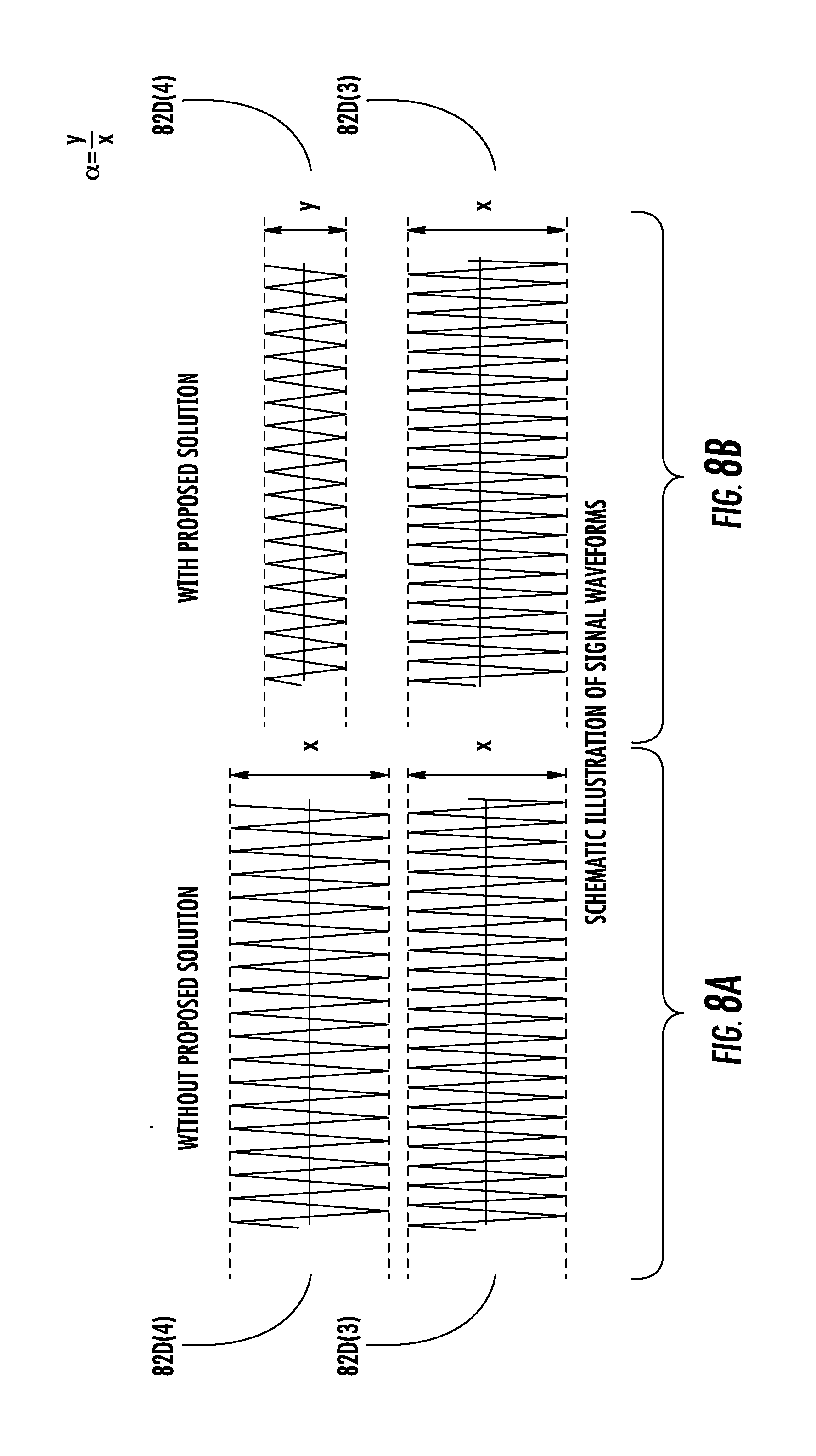
D00013
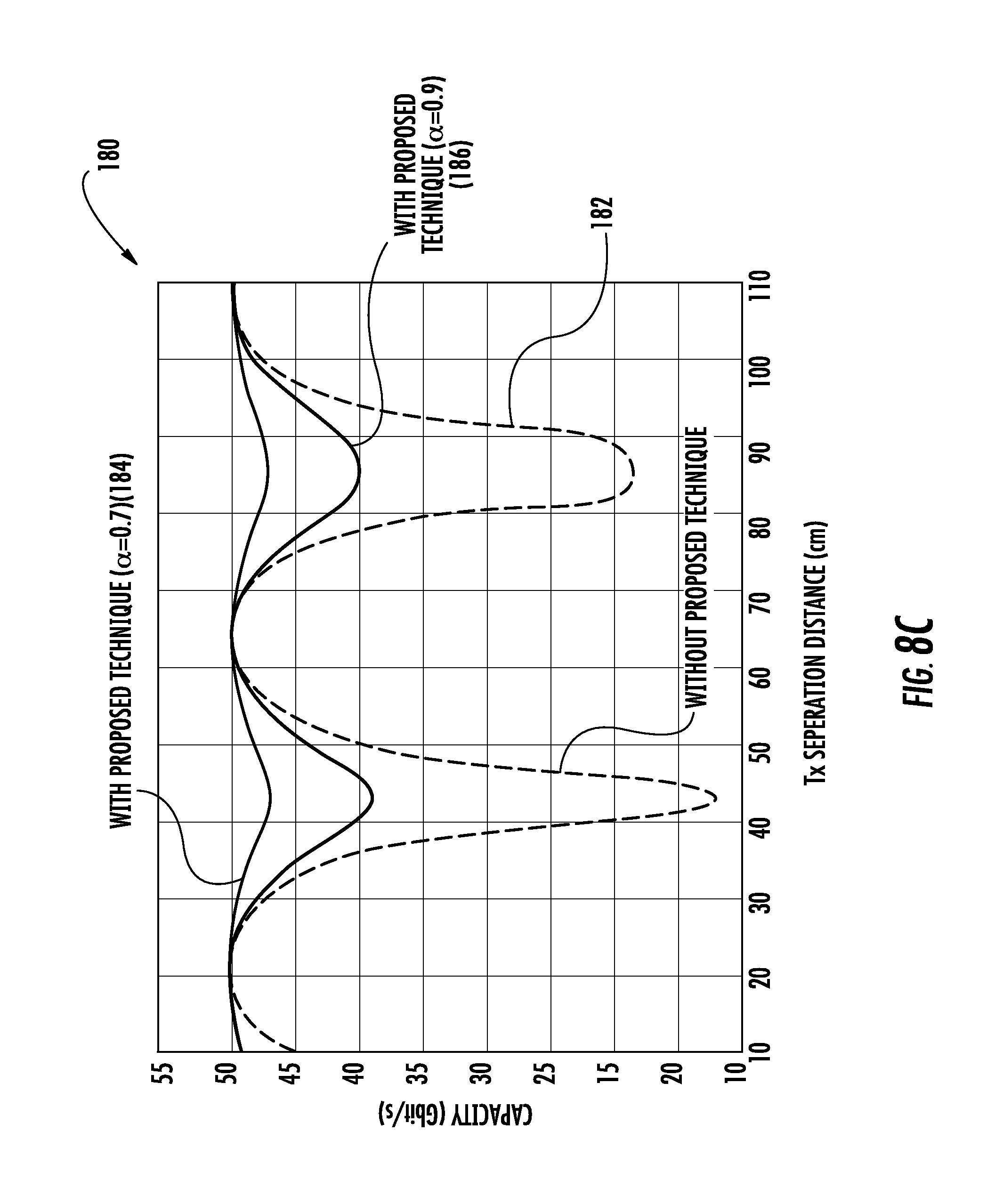
D00014
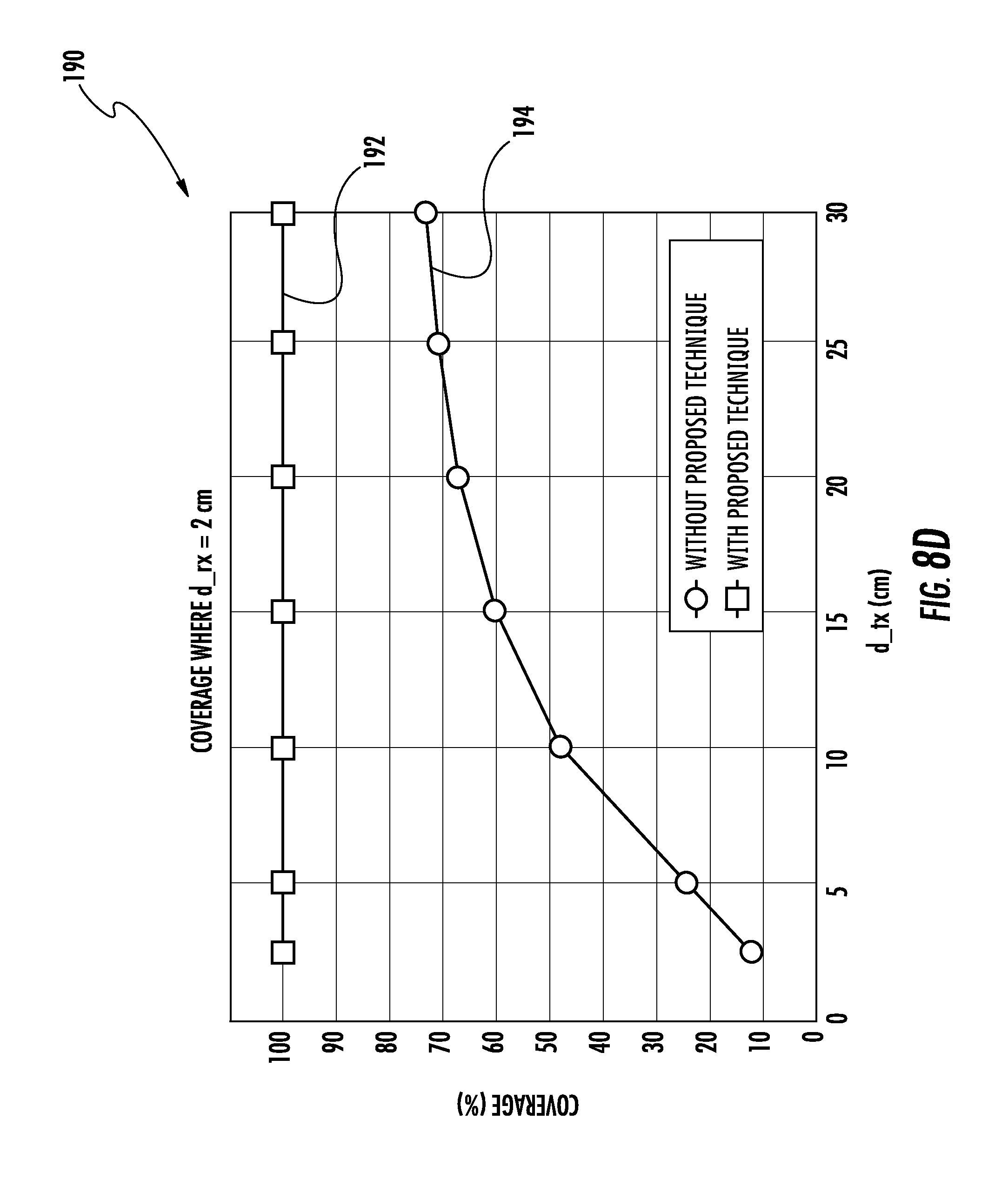
D00015
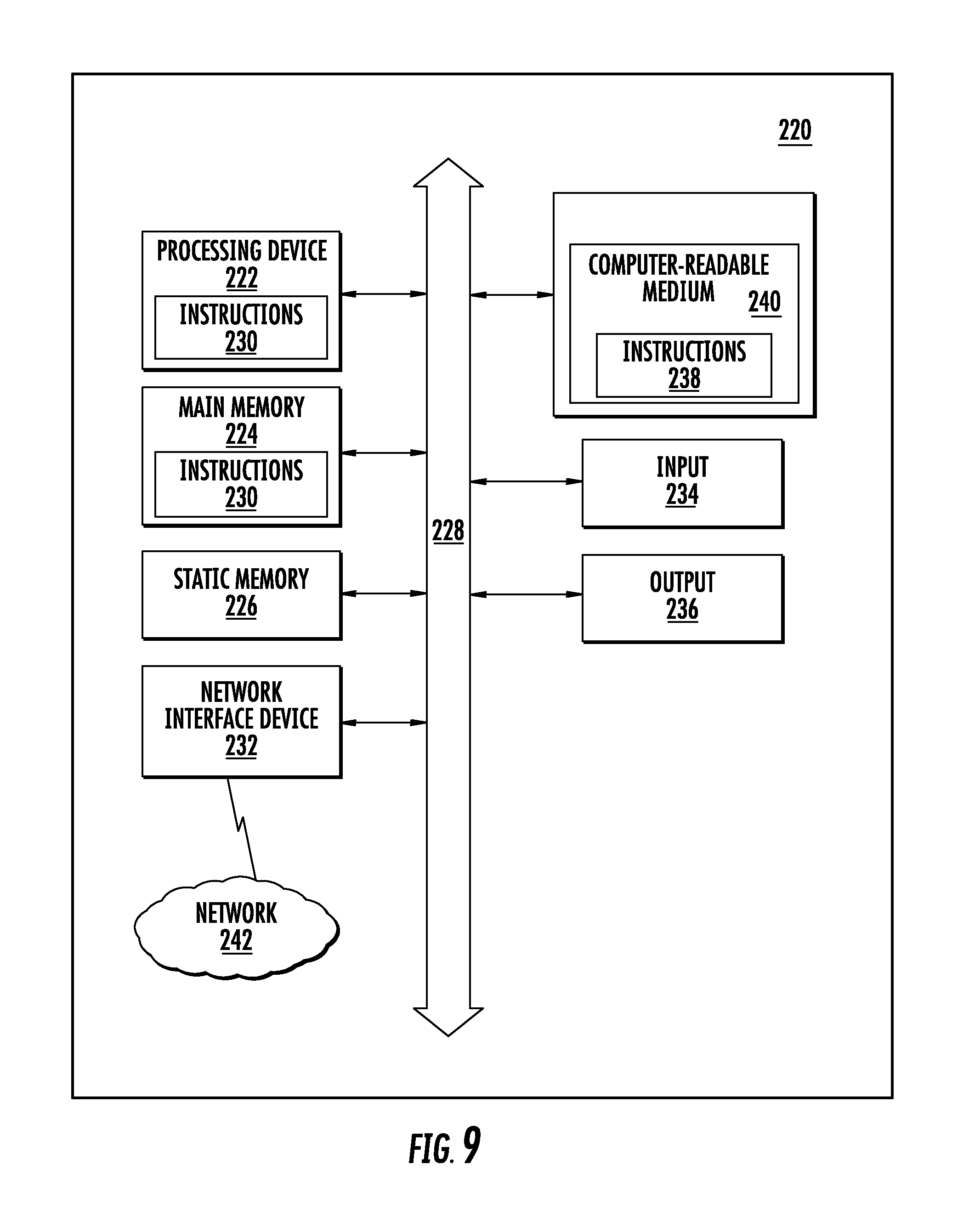
XML
uspto.report is an independent third-party trademark research tool that is not affiliated, endorsed, or sponsored by the United States Patent and Trademark Office (USPTO) or any other governmental organization. The information provided by uspto.report is based on publicly available data at the time of writing and is intended for informational purposes only.
While we strive to provide accurate and up-to-date information, we do not guarantee the accuracy, completeness, reliability, or suitability of the information displayed on this site. The use of this site is at your own risk. Any reliance you place on such information is therefore strictly at your own risk.
All official trademark data, including owner information, should be verified by visiting the official USPTO website at www.uspto.gov. This site is not intended to replace professional legal advice and should not be used as a substitute for consulting with a legal professional who is knowledgeable about trademark law.