Dielectric-free metal-only dipole-coupled radiating array aperture with wide field of view
Boryssenko , et al.
U.S. patent number 10,256,545 [Application Number 16/017,410] was granted by the patent office on 2019-04-09 for dielectric-free metal-only dipole-coupled radiating array aperture with wide field of view. This patent grant is currently assigned to NUVOTRONICS, INC. The grantee listed for this patent is Nuvotronics, INC. Invention is credited to Anatoliy O. Boryssenko, Benjamin L. Cannon, Kenneth Vanhille.


| United States Patent | 10,256,545 |
| Boryssenko , et al. | April 9, 2019 |
Dielectric-free metal-only dipole-coupled radiating array aperture with wide field of view
Abstract
Dielectric-free, metal-only, dipole-coupled radiating array aperture with wide field of view.
| Inventors: | Boryssenko; Anatoliy O. (Belchertown, MA), Vanhille; Kenneth (Cary, NC), Cannon; Benjamin L. (Cary, NC) | ||||||||||
|---|---|---|---|---|---|---|---|---|---|---|---|
| Applicant: |
|
||||||||||
| Assignee: | NUVOTRONICS, INC (Radford,
VA) |
||||||||||
| Family ID: | 53272112 | ||||||||||
| Appl. No.: | 16/017,410 | ||||||||||
| Filed: | June 25, 2018 |
Prior Publication Data
| Document Identifier | Publication Date | |
|---|---|---|
| US 20180309205 A1 | Oct 25, 2018 | |
Related U.S. Patent Documents
| Application Number | Filing Date | Patent Number | Issue Date | ||
|---|---|---|---|---|---|
| 15602353 | May 23, 2017 | 10008779 | |||
| 14567655 | Dec 11, 2014 | 10027030 | |||
| 61914693 | Dec 11, 2013 | ||||
| Current U.S. Class: | 1/1 |
| Current CPC Class: | H01Q 5/40 (20150115); H01Q 5/25 (20150115); H01Q 9/28 (20130101); H01Q 25/00 (20130101); H01Q 9/26 (20130101); H01Q 21/062 (20130101); H01Q 23/00 (20130101); H01Q 1/48 (20130101); H01Q 21/26 (20130101) |
| Current International Class: | H01Q 21/06 (20060101); H01Q 5/40 (20150101); H01Q 25/00 (20060101); H01Q 9/28 (20060101); H01Q 21/26 (20060101); H01Q 1/48 (20060101); H01Q 9/26 (20060101); H01Q 23/00 (20060101); H01Q 5/25 (20150101) |
References Cited [Referenced By]
U.S. Patent Documents
| 3157847 | November 1964 | Williams |
| 3618105 | November 1971 | Bruene |
| 3820041 | June 1974 | Gewartowski |
| 4218685 | August 1980 | Frosch |
| 4647942 | March 1987 | Counselman, III |
| 4677393 | June 1987 | Sharma |
| 4994817 | February 1991 | Munson |
| 5557291 | September 1996 | Chu |
| 6101705 | August 2000 | Wolfson |
| 6317099 | November 2001 | Zimmerman |
| 6323809 | November 2001 | Maloney |
| 6356241 | March 2002 | Jaeger |
| 6512487 | January 2003 | Taylor |
| 6842158 | January 2005 | Jo |
| 7079079 | July 2006 | Jo |
| 7109936 | September 2006 | Mizoguchi |
| 7463210 | December 2008 | Rawnick |
| 7764236 | July 2010 | Hill |
| 7889147 | February 2011 | Tam |
| 7948335 | May 2011 | Sherrer |
| 8325093 | December 2012 | Holland |
| 9130262 | September 2015 | Park |
| 9306254 | April 2016 | Hovey |
| 1000877 | June 2018 | Boryssenko |
| 2003/0231134 | December 2003 | Yarasi |
| 2004/0263410 | December 2004 | Teillet |
| 2005/0013977 | January 2005 | Wong |
| 2005/0040994 | February 2005 | Mazoki |
| 2005/0116862 | June 2005 | du Toit |
| 2006/0232489 | October 2006 | Bisiules |
| 2007/0126651 | June 2007 | Snyder |
| 2008/0074339 | March 2008 | Lee |
| 2008/0079644 | April 2008 | Cheng |
| 2009/0051619 | February 2009 | Hook |
| 2009/0284419 | November 2009 | Kim |
| 2010/0007572 | January 2010 | Jones |
| 2011/0025574 | February 2011 | Tiezzi |
| 2011/0057852 | March 2011 | Holland |
| 2012/0146869 | June 2012 | Holland |
| 2013/0002501 | January 2013 | Li |
| 2013/0169505 | July 2013 | Shmuel |
| 2014/0103423 | April 2014 | Ohlsson |
| 2014/0354500 | December 2014 | Tayama |
| 2015/0162665 | June 2015 | Boryssenko |
| 2016/0268695 | September 2016 | Zavrel, Jr. |
| 2016/0370568 | December 2016 | Toussaint |
| 2017/0025767 | January 2017 | Elsallal |
| 2017/0256859 | September 2017 | Boryssenko |
| 2018/0323510 | November 2018 | Boryssenko |
| 2007076105 | Jul 2007 | WO | |||
| 2014011675 | Jan 2014 | WO | |||
Other References
|
Ghannoum, H. et al. "Probe Fed Stacked Patch Antenna for UWB Sectoral Applications," IEEE International Conference on Ultra-Wideband 2005. pp. 97-102. cited by applicant . A. Boryssenko, J. Arroyo, R. Reid, M.S. Heimbeck, "Substrate free G-band Vivaldi antenna array design, fabrication and testing" 2014 IEEE International Conference on Infrared, Millimeter, and Terahertz Waves, Tucson, Sep. 2014. cited by applicant . B. Cannon, K. Vanhille, "Microfabricated Dual-Polarized, W-band Antenna Architecture for Scalable Line Array Feed," 2015 IEEE Antenna and Propagation Symposium, Vancouver, Canada, Jul. 2015. cited by applicant . D. Filipovic, G. Potvin, D. Fontaine, C. Nichols, Z. Popovic, S. Rondineau, M. Lukic, K. Vanhille, Y. Saito, D. Sherrer, W. Wilkins, E. Daniels, E. Adler, and J. Evans, "Integrated micro-coaxial Ka-band antenna and array," GomacTech 2007 Conference, Mar. 2007. cited by applicant . E. Cullens, L. Ranzani, E. Grossman, Z. Popovic, "G-Band Frequency Steering Antenna Array Design and Measurements," Proceedings of the XXXth URSI General Assembly, Istanbul, Turkey, Aug. 2011. cited by applicant . Gao, S. et al. "A Broad-Band Dual-Polarized Microstrip Patch AntennaWith Aperture Coupling," IEEE Transactions on Antennas and Propagation, vol. 51, No. 4, Apr. 2003. pp. 898-900. cited by applicant . Gao, S.C., et al., Dual-polarised Wideband Microstrip Antenna, Electronic Letters, Aug. 30, 2001, vol. 37, No. 18, pp. 1106-1107. cited by applicant . Guo, Y.X. et al. "L-probe proximity-fed short-circuited patch antennas," Electronics Letters, vol. 35 No. 24, Nov. 25, 1999. pp. 2069-2070. cited by applicant . H. Zhou, N. A. Sutton, D. S. Filipovic, "Surface micromachined millimeter-wave log-periodic dipole array antennas," IEEE Trans. Antennas Propag., Oct. 2012, vol. 60, No. 10, pp. 4573-4581. cited by applicant . H. Zhou, N. A. Sutton, D. S. Filipovic, "Wideband W-band patch antenna," 5th European Conference on Antennas and Propagation , Rome, Italy, Apr. 2011, pp. 1518-1521. cited by applicant . Holzheimer, et al., Performance Enhancements with Applications of the Coaxial Cavity Antenna, pp. 171-193. cited by applicant . Hsu, Wen-Hsiu et al. "Broadband Aperture-Coupled Shorted-Patch Antenna," Microwave and Optical Technology Letters, vol. 28, No. 5, Mar. 5, 2001. pp. 306-307. cited by applicant . J. M. Oliver, J.-M. Rollin, K. Vanhille, S. Raman, "A W-band micromachined 3-D cavity-backed patch antenna array with integrated diode detector," IEEE Trans. Microwave Theory Tech., Feb. 2012, vol. 60, No. 2, pp. 284-292. cited by applicant . J. M. Oliver, P. E. Ralston, E. Cullens, L. M. Ranzani, S. Raman, K. Vanhille, "A W-band Micro-coaxial Passive Monopulse Comparator Network with Integrated Cavity--Backed Patch Antenna Array," 2011 IEEE MTT-S Int. Microwave, Symp., Baltimore, MD, Jun. 2011. cited by applicant . J. Mruk, Z. Hongyu, M. Uhm, Y. Saito, D. Filipovic, "Wideband mm-Wave Log-Periodic Antennas," 3rd European Conference on Antennas and Propagation, pp. 2284-2287, Mar. 2009. cited by applicant . J. R. Mruk, N. Sutton, D. S. Filipovic, "Micro-coaxial fed 18 to 110 GHz planar log-periodic antennas with RF transitions," IEEE Trans. Antennas Propag., vol. 62, No. 2, Feb. 2014, pp. 968-972. cited by applicant . J.R. Mruk, Y. Saito, K. Kim, M. Radway, D. Filipovic, "A directly fed Ku- to W-band 2-arm Archimedean spiral antenna," Proc. 41st European Microwave Conf., Oct. 2011, pp. 539-542. cited by applicant . K. M. Lambert, F. A. Miranda, R. R. Romanofsky, T. E. Durham, K. J. Vanhille, "Antenna characterization for the Wideband Instrument for Snow Measurements (WISM)," 2015 IEEE Antenna and Propagation Symposium, Vancouver, Canada, Jul. 2015. cited by applicant . K. Vanhille, M. Lukic, S. Rondineau, D. Filipovic, and Z. Popovic, "Integrated micro-coaxial passive components for millimeter-wave antenna front ends," 2007 Antennas, Radar, and Wave Propagation Conference, May 2007. cited by applicant . L. Ranzani, N. Ehsan, Z. Popovic, "G-band frequency-scanned antenna arrays," 2010 IEEE APS-URSI International Symposium, Toronto, Canada, Jul. 2010. cited by applicant . M. Lukic, D. Fontaine, C. Nichols, D. Filipovic, "Surface micromachined Ka-band phased array antenna," Presented at Antenna Applic. Symposium, Monticello, IL, Sep. 2006. cited by applicant . M. Lukic, K. Kim, Y. Lee, Y. Saito, and D. S. Filipovic, "Multi-physics design and performance of a surface micromachined Ka-band cavity backed patch antenna," 2007 SBMO/IEEE Int. Microwave and Optoelectronics Conf., Oct. 2007, pp. 321-324. cited by applicant . M. V. Lukic, and D. S. Filipovic, "Integrated cavity-backed ka-band phased array antenna," Proc. IEEE-APS/URSI Symposium, Jun. 2007, pp. 133-135. cited by applicant . M. V. Lukic, and D. S. Filipovic, "Surface-micromachined dual Ka-and cavity backed patch antenna," IEEE Trans. Antennas Propag., vol. 55, No. 7, pp. 2107-2110, Jul. 2007. cited by applicant . Mruk, J.R., Saito, Y., Kim, K., Radway, M., Filipovic, D.S., "Directly fed millimetre-wave two-arm spiral antenna," Electronics Letters, Nov. 25 2010, vol. 46 , issue 24, pp. 1585-1587. cited by applicant . N. Chamberlain, M. Sanchez Barbetty, G. Sadowy, E. Long, K. Vanhille, "A dual-polarized metal patch antenna element for phased array applications," 2014 IEEE Antenna and Propagation Symposium, Memphis, Jul. 2014. pp. 1640-1641. cited by applicant . N. Jastram, D. S. Filipovic, "Parameter study and design of W-band micromachined tapered slot antenna," Proc. IEEE-APS/URSI Symposium, Orlando, FL, Jul. 2013, pp. 434-435. cited by applicant . N. Sutton, D.S. Filipovic, "Design of a K- thru Ka-band modified Butler matrix feed for a 4-arm spiral antenna," 2010 Loughborough Antennas and Propagation Conference, Loughborough, UK, Nov. 2010, pp. 521-524. cited by applicant . N.A. Sutton, D. S. Filipovic, "V-band monolithically integrated four-arm spiral antenna and beamforming network," Proc. IEEE-APS/URSI Symposium, Chicago, IL, Jul. 2012, pp. 1-2. cited by applicant . Nakano, M., et al., "Feed Circuits of Double-Layered Self-Diplexing Antenna for Mobile Satelite Communications", Transactions on Antennas and Propagation, vol. 40, No. 1, Oct. 1992, pp. 1269-1271. cited by applicant . Oliver, J.M. et al., "A 3-D micromachined W-band cavity backed patch antenna array with integrated rectacoax transition to wave guide," 2009 Proc. IEEE International Microwave Symposium, Boston, MA 2009. cited by applicant . Sevskiy, S. and Wiesbeck, W., "Air-Filled Stacked-Patch Antenna," ITG-Fachberichte. No. 178, (2003). pp. 53-56. cited by applicant . T. E. Durham, C. Trent, K. Vanhille, K. M. Lambert, F. A. Miranda, "Design of an 8-40 GHz Antenna for the Wideband Instrument for Snow Measurements (WISM)," 2015 IEEE Antenna and Propagation Symposium, Vancouver, Canada, Jul. 2015. cited by applicant . Tim Holzheimer, Ph.D., P .E., The Low Dispersion Coaxial Cavity As an Ultra Wideband Antenna, 2002 IEEE Conference on Ultra Wideband Systems and Technologies, pp. 333-336. cited by applicant . Vallecchi, A. et al. "Dual-Polarized Linear Series-Fed Microstrip ArraysWith Very Low Losses and Cross Polarization," IEEE Antennas and Wireless Propagation Letter, vol. 3, 2004. pp. 123-126. cited by applicant . Y. Saito, J.R. Mruk, J.-M. Rollin, D.S. Filipovic, "X- through Q- band log-periodic antenna with monolithically integrated u-coaxial impedance transformer/feeder," Electronic Letts. Jul. 2009, pp. 775-776. cited by applicant . Y. Saito, M.V. Lukic, D. Fontaine, J.-M. Rollin, D.S. Filipovic, "Monolithically Integrated Corporate-Fed Cavity-Backed Antennas," IEEE Trans. Antennas Propag., vol. 57, No. 9, Sep. 2009, pp. 2583-2590. cited by applicant . Z. Popovic, "Micro-coaxial micro-fabricated feeds for phased array antennas," in IEEE Int. Symp. on Phased Array Systems and Technology, Waltham, MA, Oct. 2010, pp. 1-10. (Invited). cited by applicant . Zurcher, J. "Broadband Patch Antennas," Chapter 3, 1995. pp. 45-61. cited by applicant . Ben Munk et al.; "A Low-Profile Broadband Phased Array Antenna"; The Ohio State University ElectroScience Laboratory, Dept. of Electrical Engineering; 2003 pp. 448-451. cited by applicant . Woorim Shin, et al. "A 108-114 GHz 4 4 Wafer-Scale Phased Array Transmitter With High-Efficiency On-Chip Antennas"; IEEE Journal of Solid-State Circuits, vol. 48, No. 9, Sep. 2013. cited by applicant . Harold A. Wheeler; "Simple Relations Derived from a Phased-Array Antenna Made of an Infinite Current Sheet"; IEEE Transactions on Antennas Propagation; Jul. 1965; pp. 506-514. cited by applicant . E. G. Magill, et al.; Wide-Angle Impedance Matching of a Planar Array Antenna by a Dielectric Sheet; IEEE Transactions on Antennas Propagation; Jan. 1966; vol. AP-14 No. 1; pp. 49-53. cited by applicant . P. W. Hannan, et al.; Impedance Matching a Phased-Array Antenna Over Wide Scan Angles by Connecting Circuits; Impedance Matching a Phased-Array Antenna; Jan. 1965 pp. 28-34. cited by applicant . James E. Dudgeon, et al.;Microstrip Technology and Its Application to Phased Array Compensation; Jan. 21, 1972; pp. 1-81. cited by applicant . Kerry Speed, et al; Progress on the 8-40 GHz Wideband Instrument for Snow Measurements(WISM); Harris.com Earth Science Tech nology Forum 2014 Oct. 28-30, 2014 Leesburg, VA; pp. 1-36. cited by applicant . Mark Jones, et al.; A New Approach to Broadband Array Design Using Tightly Coupled Elements; IEEE; 2007; pp. 1-7. cited by applicant . W. M. Qureshi et al., Fabrication of a Multi-Octave Phased Array Aperture; 6th EMRS DTC Technical Conference--Edinburgh; 2009; pp. 1-5. cited by applicant . John Forrest McCann, B.S.; On The Design of Large Bandwidth Arrays of Slot Elements With Wide Scan Angle Capabilities; Thesis The Ohio State University; 2006; pp. 1-102. cited by applicant . Tengfei Xia et al.; Design of a Tapered Balun for Broadband Arrays With Closely Spaced Elements; IEEE Antennas and Wireless Propagation Letters, vol. 8, 2009; pp. 1291-1294. cited by applicant . Justin A. Kasemodel, et al.; A Miniaturization Technique for Wideband Tightly Coupled Phased Arrays; IEEE; 2009; pp. 1-4. cited by applicant . Elias A. Alwan,, Et al.; A Simple Equivalent CircuitModel for Ultrawideband Coupled Arrays; IEEE Antennas and Wireless Propagation Letters, vol. 11, 2012; pp. 117-120. cited by applicant . Nathanael J. Smith; Development of a 180.degree. Hybrid Balun to Feed a Tightly Coupled Dipole X-Band Array; The Ohio State University 2010; pp. 1-52. cited by applicant . Justin A. Kasemodel; Realization of a Planar Low-Profile Broadband Phased Array Antenna; Dissertation, The Ohio State University 2010; pp. 1-120. cited by applicant . Justin A. Kasemodel, et al.; Low-Cost, Planar and Wideband Phased Array with Integrated Balun and Matching Network for Wide-Angle Scanning; IEEE 2010; pp. 2-4. cited by applicant . Erdinc Irci; Low-Profile Wideband Antennas Based on Tightly Coupled Dipole and Patch Elements; Dissertation, The Ohio State University 2011; pp. 1-126. cited by applicant . William F. Moulder; Novel Implementations of Ultrawideband Tightly Coupled Antenna Arrays; Dissertation, The Ohio State University 2012; pp. 1-133. cited by applicant . Ioannis Tzanidis; Ultrawideband Low-Profile Arrays of Tightly Coupled Antenna Elements: Excitation, Termination and Feeding Methods; Dissertation, The Ohio State University 2011; pp. 1-189. cited by applicant . Jonathan Doane; Wideband Low-Prole Antenna Arrays: Fundamental Limits and Practical Implementations; Dissertation, The Ohio State University 2013; pp. 1-265. cited by applicant . Justin A. Kasemodel et al.; Wideband Planar Array With Integrated Feed and Matching Network for Wide-Angle Scanning; IEEE Transactions on Antennas and Propagation, vol. 61, No. 9, Sep. 2013; pp. 4528-4537. cited by applicant . Jonathan P. Doane, et al.; Wideband, Wide Scanning Conformal Arrays with Practical Integrated Feeds; Proceedings of the "2013 International Symposium on Electromagnetic Theory"; pp. 859-862. cited by applicant . Steven S. Holland, et al.; Design and Fabrication of Low-Cost PUMA Arrays; IEEE; 2011; pp. 1976-1979. cited by applicant . Steven S. Holland; Low-Profile, Modular, Ultra-Wideband Phased Arrays; Dissertation, University of Massachusetts; Sep. 2011; pp. 1-327. cited by applicant . John T. Logan, et al.; A Review of Planar Ultrawideband Modular Antenna (PUMA) Arrays; Proceedings of the "2013 International Symposium on Electromagnetic Theory"; 2013; pp. 868-871. cited by applicant . D. Cavallo, et al.; Common-Mode Resonances in Ultra Wide Band Connected Arrays of Dipoles: Measurements from the Demonstrator and Exit Strategy; IEEE; 2009; pp. 435-438. cited by applicant . J. J. Lee, et al.; Performance of a Wideband (3-14 GHz) Dual-pol Array; IEEE; 2004; pp. 551-554. cited by applicant . Jian Bai, et al.; Ultra-wideband Slot-loaded Antipodal Vivaldi Antenna Array; IEEE; 2011; pp. 79-81. cited by applicant . E. Garca I, et al.; Elimination of Scan Impedance Anomalies in Ultra-Wide Band Phased Arrays of Differentially Fed Tapered Slot Antenna Elements; IEEE; 2008; pp. 1-4. cited by applicant . Eloy de Lera Acedo, et al.; Study and Design of a Differentially-Fed Tapered Slot Antenna Array; IEEE Transactions on Antennas and Propagation, vol. 58, No. 1, Jan. 2010; pp. 68-78. cited by applicant . Y. Chen, et al.; A Novel Wideband Antenna Array With Tightly Coupled Octagonal Ring Elements; Progress in Electromagnetics Research, vol. 124, 55-70; 2012. cited by applicant . J. Y. Li; Design of Broadband Compact Size Antenna Comprised of Printed Planar Dipole Pairs; Progress in Electromagnetics Research Letters, vol. 12, 99-109; 2009. cited by applicant . Mats Gustafsson; Broadband array antennas using a self-complementary antenna array and dielectric slabs; CODEN:LUTDEX/(TEAT-7129)/1-8; Dec. 13, 2004. cited by applicant . Terry Richard Vogler; Analysis of the Radiation Mechanisms in and Design of Tightly-Coupled Antenna Arrays; Dissertation, Virginia Polytechnic Institute and State University; Sep. 10, 2010; pp. 1-251. cited by applicant . S. G. Hay, et al.; Analysis of common-mode effects in a dual-polarized planar connected-array antenna; Radio Science, vol. 43, RS6SO4, doi:10.1029/2007RS003798; 2008. cited by applicant . A. Chippendale et al.; Chequerboard Phased Array Feed Testing for ASKAP; May 3, 2010; pp. 1-41. cited by applicant . Yan Fei, et al.; A Simple Wideband Dual-Polarized Array With Connected Elements; University of Electronic Science and Technology of China (UESTC); 2013; pp. 1-21. cited by applicant . Fei Yan, et al. ; A Simple Wideband Dual-Polarized Array With Connected Elements; Institute of Applied Physics and Computational Mathematics; 978-1-4673-5317-5/13 2013 IEEE. cited by applicant . Tomasz Michna, et al.; Characterization of an Impulse-Transmitting UWB Antenna Array with Dispersive Feed Network; Characterization of an Impulse-Transmitting UWB; 2008; pp. 59-62. Antenna Array with Dispersive Feed Network. cited by applicant . Martin Wagner, et al.; Multi-B and Polarization-Versatile Array Antenna for Smart Antenna Applications in Cellular Systems; 2004 EEE MTT-S Digest; pp. 1769-1772. cited by applicant . Jeremie Bourqui, et al.; Balanced Antipodal Vivaldi Antenna With Dielectric Director for Near-Field Microwave Imaging; EEE Transactions on Antennas and Propagation, vol. 58, No. 7; Jul. 2010. cited by applicant . R.N. Simons, et al.; Impedance matching of tapered slot antenna using a dielectric transformer; Electronics Letters Nov. 26, 1998 vol. 34 No. 24. cited by applicant . S. A. Adamu, et al.; Review on Gain and Directivity Enhancement Techniques of Vivaldi Antennas; International Journal of Scientific & Engineering Research, vol. 8, Issue 3, Mar. 2017; ISSN 2229-5518. cited by applicant . S. Livingston, et al.; Evolution of Wide Band Array Designs; 2011; IEEE pp. 1957-1960. cited by applicant . J. J. Lee,W et al.; Wide Band Long Slot Array Antennas; IEEE; 2003; pp. 452-455. cited by applicant . Johnson J. H. Wang; A New Planar Multioctave Broadband Traveling-Wave Beam-Scan Array Antenna; Wang Electro-Opto Corporation; 2007; pp. 1-4. cited by applicant . John Toon; New planar design allows fabrication of ultra-wideband, phased-array antennas; 100-TO-1 Bandwidth @ Winter 2006; pp. 18-19. cited by applicant . Hans Steyskal, et al.; Design of Realistic Phased Array Patch Elements Using a Genetic Algorithm; Air Force Research Laboratory; 2010; pp. 246-252. cited by applicant . Benjamin Riviere, et al.; Ultrawideband Multilayer Printed Antenna Arrays With Wide Scanning Capability; 2015; IEEE; 514-515. cited by applicant . Boryssenko, et al.; A Matlab Based Universal CEM CAD Optimizer; 2012; IEEE International Symposium on Antennas and Propagation; pp. 1-25. cited by applicant . Justin A. Kasemodel, et al.; A Novel Non-Symmetric Tightly Coupled Element for Wideband Phased Array Apertures; Dissertation The Ohio State University; 2010; pp. 1-13. cited by applicant . Markus H. Novak, et al.; Ultra-Wideband Phased Array Antennas for Satellite Communications up to Ku- and Ka-Band; May 2015; pp. 1-6. cited by applicant . Wajih Elsallal, et al.; Charateristics of Decade-bandwidth, Balanced Antipodal Vivaldi Antenna (BAVA) Phased Arrays with Time-Delay Beamformer Systems; IEEE International Symposium on Phased Array Systems and Technology. cited by applicant . Michel Arts, et al.; Broadband Differentially Fed Tapered Slot Antenna Array for Radio Astronomy Applications; 2009; 3rd European Conference on Antennas and Propagation; pp. 1-5. cited by applicant . Yongwei Zhang, et al.; Octagonal Ring Antenna for a Compact Dual-Polarized Aperture Array; IEEE Transactions on Antennas and Propagation, vol. 59, No. 10, Oct. 2011; pp. 3927-3932. cited by applicant . Hisao Iwasaki, et al.; A Circularly Polarized Microstrip ANfENNA Using Singly-FED Proximity CCUPLED Feed; Proceedings of ISAP '92, Sapporo, Japan; pp. 797-800. cited by applicant . Hansen, Robert C. Phased array antennas. vol. 213. John Wiley & Sons, 2009. cited by applicant . Herd, J., and S. Duffy. "Overlapped digital subarray architecture for multiple beam phased array radar." Proceedings of the 5th European Conference on Antennas and Propagation (EUCAP). IEEE, 2011. cited by applicant . L. Ranzani, D. Kuester, K. J. Vanhille, A. Boryssenko, E. Grossman and Z. Popovic, "G-band Micro-fabricated Frequency-steered Arrays with 2deg/GHz Beam Steering," IEEE Transactions on Terahertz Science and Technology, vol. 3, No. 5, Sep. 2013. cited by applicant . Kindt, Rick W., and W. Raymond Pickles. All-Metal Flared-Notch Array Radiator for Ultrawideband Applications. No. NRL/MR/5310-10-9279. Naval Research Lab Washington DC Radar Analysis Branch, 2010. cited by applicant . Doane, Jonathan P., Kubilay Sertel, and John L. Volakis. "A wideband, wide scanning tightly coupled dipole array with integrated balun (TCDA-IB)." IEEE Transactions on Antennas and Propagation 61.9 (2013): 4538-4548. cited by applicant . Moulder, William F., Kubilay Sertel, and John L. Volakis. "Superstrate-enhanced ultrawideband tightly coupled array with resistive FSS." IEEE Transactions on Antennas and Propagation 60.9 (2012): 4166-4172. cited by applicant . Papantonis, Dimitrios K., and John L. Volakis. "Dual-polarization TCDA-IB with substrate loading." 2014 IEEE Antennas and Propagation Society International Symposium (APSURSI). IEEE, 2014. cited by applicant . Herd, J., et al. "Multifunction Phased Array Radar (MPAR) for aircraft and weather surveillance." 2010 IEEE Radar Conference. IEEE, 2010. cited by applicant . J. D. Dyson, "The equiangular spiral antenna," Wright Air Development Center, 1957. cited by applicant . Frank B. Gross; Ultra-wideband antenna arrays--The basics--Part I; Apr. 7, 2011. cited by applicant . The ARRL Atenna Book, by Gerald Hall (Year: 1988). cited by applicant . Office Action dated Nov. 8, 2018 for U.S. Appl. No. 15/373,016 (pp. 1-20). cited by applicant. |
Primary Examiner: Levi; Dameon E
Assistant Examiner: Islam; Hasan Z
Attorney, Agent or Firm: Haun; Niels Dann, Dorfman, Herrell & Skillman, P.C.
Parent Case Text
RELATED APPLICATIONS
This application is a continuation application of U.S. application Ser. No. 15/602,353, filed May 23, 2017 now U.S. patent Ser. No. 10/008,779, which is a continuation application of U.S. application Ser. No. 14/567,655, filed Dec. 11, 2014, which in turn claims the benefit of priority of U.S. Provisional Application No. 61/914,693, filed on Dec. 11, 2013, the entire contents of which applications are incorporated herein by reference.
Claims
What is claimed is:
1. A radiator structure, comprising: a ground surface having a plurality of openings disposed therethrough; first and second antenna loops with each loop disposed in a respective plane perpendicular to the ground surface, each loop having a first end shorted to the ground surface and each loop having a second end disposed in a respective one of the plurality of openings, wherein the antenna loops comprise self-supporting metal-only structures such that the antenna loops are not embedded in dielectric materials; a third antenna loop disposed in the same plane as the first antenna loop, the third loop having a first end shorted to the ground surface and a second end disposed in a respective one of the plurality of openings; and a fourth antenna loop disposed in the same plane as the second antenna loop, the fourth loop having a first end shorted to the ground surface and a second end disposed in a respective one of the plurality of openings, wherein the first, second, third, and fourth antenna loops are arranged in a plus-shaped pattern and the grounded ends of the first, second, third, and fourth antenna loops are disposed proximate the center of the plus-shape.
2. A radiator structure, comprising: a ground surface having a plurality of openings disposed therethrough; first and second antenna loops with each loop disposed in a respective plane perpendicular to the ground surface, each loop having a first end shorted to the ground surface and each loop having a second end disposed in a respective one of the plurality of openings, wherein the antenna loops comprise self-supporting metal-only structures such that the antenna loops are not embedded in dielectric materials; a third antenna loop disposed in the same plane as the first antenna loop, the third loop having a first end shorted to the ground surface and a second end disposed in a respective one of the plurality of openings; and a fourth antenna loop disposed in the same plane as the second antenna loop, the fourth loop having a first end shorted to the ground surface and a second end disposed in a respective one of the plurality of openings, wherein the first, second, third, and fourth antenna loops are arranged in a plus-shaped pattern and the plurality of openings are disposed proximate the center of the plus-shape.
3. A two-dimensional array of the radiator structure of claim 1 or 2.
4. The array of claim 3, wherein the two dimensional array comprises dual-polarized differentially-fed shorted dipoles.
5. The array of claim 3, wherein a selected pair of adjacent antenna loops in the two dimensional array are capacitively coupled to one another.
Description
FIELD OF THE INVENTION
The present invention relates generally to radiating array apertures, and more particularly, but not exclusively, to coupled-dipole arrays which may be metal-only and dielectric-free.
BACKGROUND OF THE INVENTION
There are still unmet demands from defense and commercial markets for very low-profile array antennas capable of supporting transmit and receive operations with arbitrary polarization states and the ability to scan down to angles approaching the grazing regime with acceptable active reflection coefficients. Besides just the aforementioned major electrical requirements, such prospective arrays have to be of high radiation efficiency and low insertion loss along with their advanced structural properties. Such structural properties may include low complexity to fabricate, assemble and install while minimizing or excluding manual labor, as well as mechanical ability to withstand, for example, multi-G impacts. Also using predominantly low-cost fabrication materials and technologies suitable for mass production is preferable to achieve break-through technical and economic features.
SUMMARY OF THE INVENTION
In one of its aspects, the invention relates to the design and implementation of ultra--(i.e., up to several octaves or up to and/or surpassing decade bandwidth), dielectric-free, metal-only, very-low-profile array of radiating apertures capable of supporting transmit and receive operation with arbitrary polarization states. The array of radiating apertures may be structurally-simple and suitable for additive manufacturing. The array of radiating apertures in accordance with the present invention may provide an antenna that is capable of scanning to angles approaching the grazing regime with acceptable active reflection coefficients. An array cell may be made from one dipole if just one polarization is required and/or from two such orthogonal dipoles to produce arbitrary polarization states. The dipoles may be self-supporting metal structures with integrated edge-coupling and feed networks to connect the dipoles to RF transmitter/receiver circuits below the ground plane. In addition, the array of electrically connected dipoles may be placed above and in parallel to the ground plane to permit unidirectional radiation in the upper semi-sphere.
Devices of the present invention may exclude the use of dielectric construction elements, because it can be difficult to find good low-loss dielectric for high frequencies. Dielectrics may introduce additional losses especially at higher frequencies, and can contribute to additional weight, size and cost. In addition, a top thick dielectric covering might cause array blindness by launching a surface wave instead of radiating the electromagnetic energy in designated scan directions. A metal-only radiator structure of the present invention may be made of two symmetrical loop-like, three-branch, metal parts. The first, generally vertical branch may start from a feed point near the ground plane enabling connection to the front-end circuits below the ground and may extend to certain height. Functionally, the first branch may serve for transmission of RF signals between the circuits below the ground plane and a second radiating branch. This second, generally horizontal section branch may form a radiating arm of the dipole. The second branch's functional role in the array may be to transmit or receive electromagnetic energy. At the other end, the second, generally horizontal branch may extend close to the boundary of the array cell where a third, generally vertical branch starts. This third branch may then be shorted to ground. The function of this third, generally vertical branch may be twofold: (i) electrically, it may enable coupling between adjacent array cells through electro-magnetic coupling between the vertical sections of adjacent cells; (ii) mechanically, it may support the whole structure. Indeed, the structures of the present invention may be self-supporting and not require any additional support. In addition, the structures may be described by several parameters including cross-sectional dimensions, viz. to vertical ones and horizontal ones. Further, the second branch may start closer to the ground plane on the feed side than it ends on the side near the support. This may be done for impedance matching over a greater bandwidth than what would be typical for flat precisely horizontal branches. Moreover, the vertical branches do not have to couple using flat vertical surfaces. Coupling could be implemented using interwoven or interleaved edges, which would provide additional degrees of design freedom.
For some set of geometrical dimensions, a 100 Ohm differential impedance can be supported that enables next transformation to a pair of 50 Ohm single-ended impedance feeds below the ground plane. No additional impedance transformation is required. In the array structure of the present invention, common mode resonance may be shifted to the higher frequency end. Thus, the common mode resonance does not affect the major array passband. In the present structures, a bandwidth greater than an octave is supported. For example, for a 0.75 mm mm tall radiator (height of the third branch) the array can operate across 40-120 GHz and so on. In this configuration, the size of the unit cell is 1.4 mm on an edge. The cross section of the dipole structure could be between 50 microns and 250 microns or more. Moreover, the array may be configured to support arbitrary polarization states by combining two orthogonal linear polarizations. A dual-linear polarized array layout may be made in off-set or phase-center coincident mode.
BRIEF DESCRIPTION OF THE DRAWINGS
The foregoing summary and the following detailed description of exemplary embodiments of the present invention may be further understood when read in conjunction with the appended drawings, in which:
FIGS. 1a-1c schematically illustrate an exemplary configuration of a unit cell of a single-polarized antenna in accordance with the present invention, in which FIG. 1a illustrates a top-down view of the unit cell, FIG. 1b illustrates a isometric view, and FIG. 1c illustrates a cross-sectional view of FIG. 1b taken down a midline of differentially-fed shorted arms of the antenna;
FIG. 1d schematically illustrates an alternative configuration of a unit cell of a single-polarized antenna in accordance with the present invention;
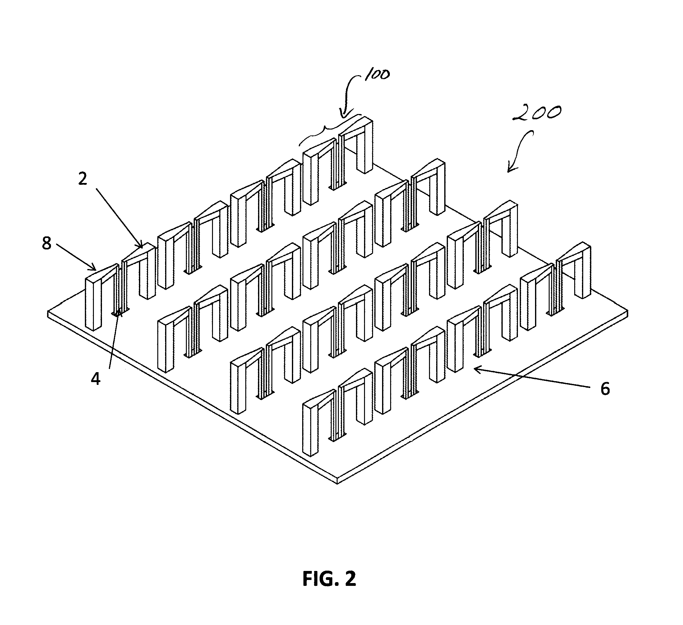
FIG. 2 schematically illustrates a four-element by four-element two-dimensional array of the single-polarized unit cell depicted in FIGS. 1a-1c;
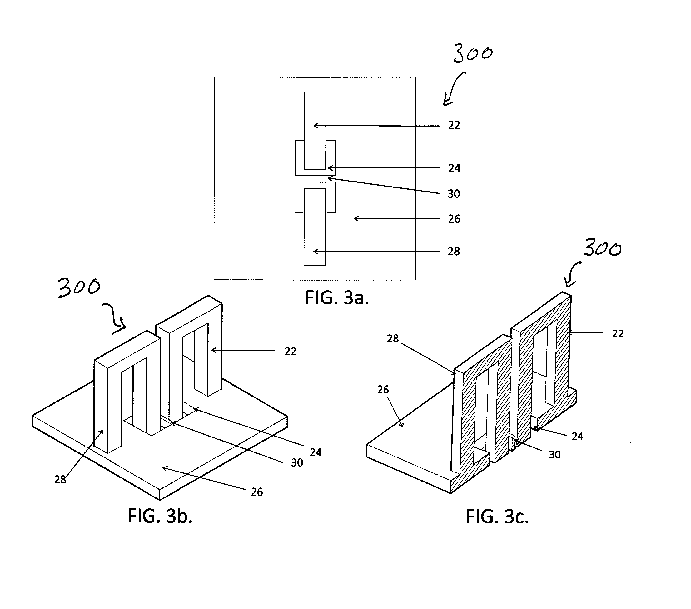
FIGS. 3a-3c schematically illustrate another exemplary configuration of a unit cell of a single-polarized antenna similar to that of FIGS. 1a-1c but having a uniform cross-section in the antenna portions, in which FIG. 3a illustrates a top-down view of the unit cell, FIG. 3b illustrates a isometric view, and FIG. 3c illustrates a cross-sectional view of FIG. 3b;
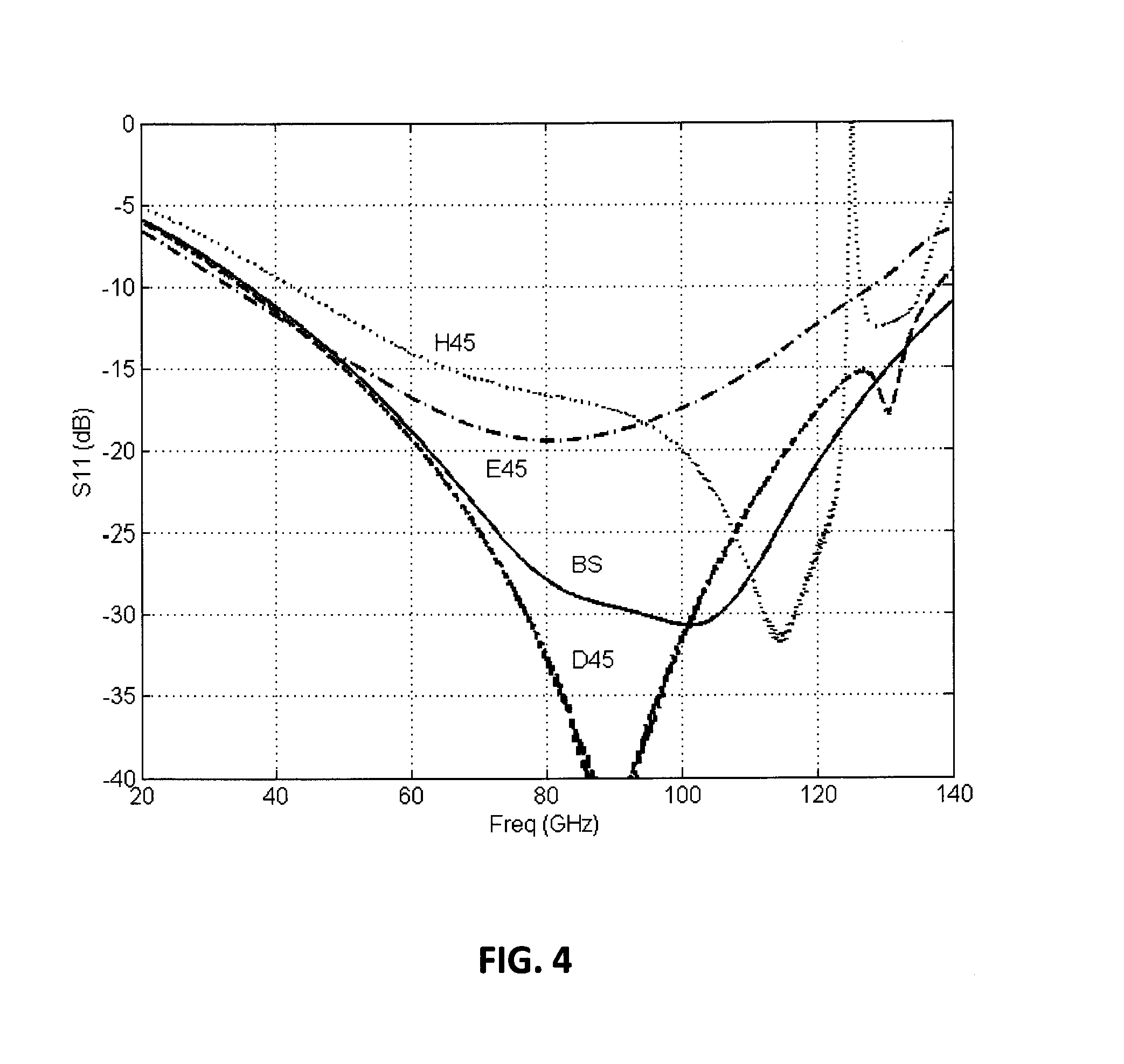
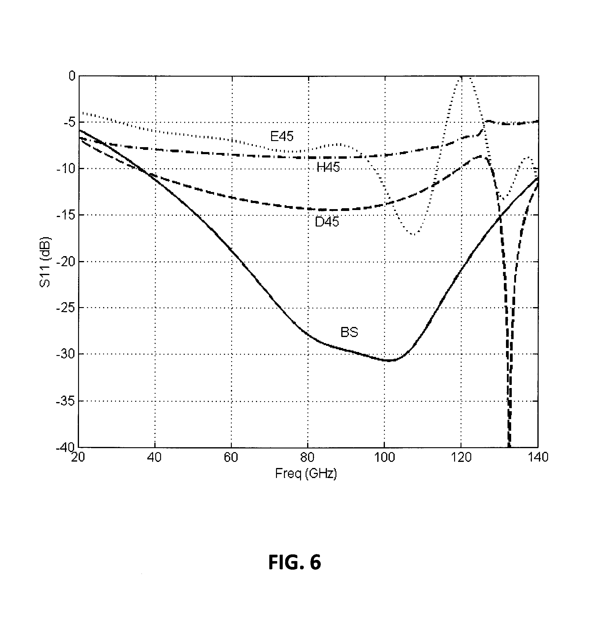
FIGS. 4-6 illustrate the expected performance of an antenna of the present invention;
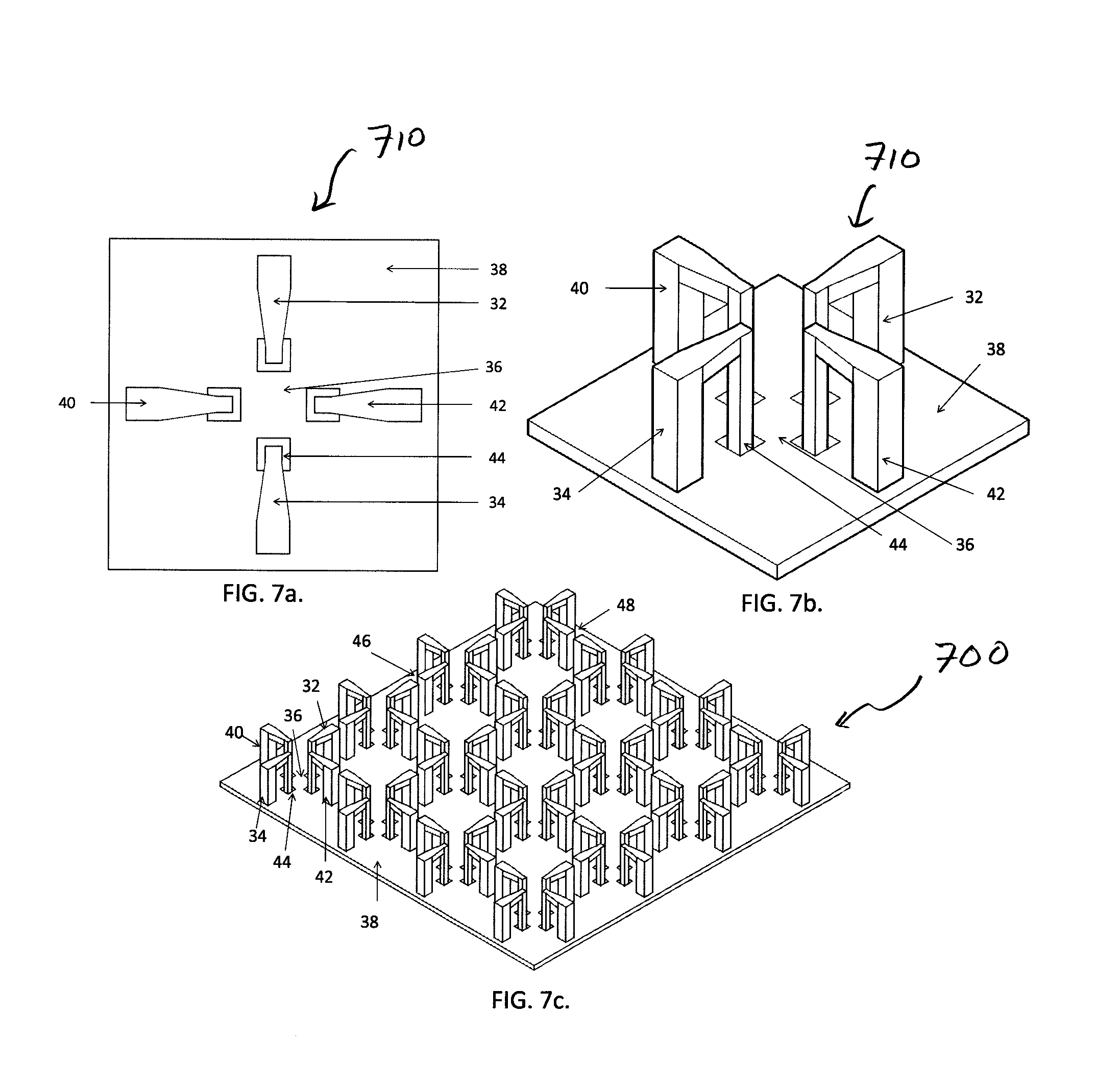
FIGS. 7a-7c schematically illustrate a two-dimensional, 4-element by 4-element array of dual-polarized, differentially-fed, shorted dipoles in accordance with the present invention, in which FIG. 7a illustrates a top-down view of a unit cell of the array, FIG. 7b illustrates a isometric view of the unit cell, and FIG. 7c illustrates an isometric view of the array;
FIGS. 8a-8c schematically illustrate a further two-dimensional, 4-element by 4-element array of dual-polarized, differentially-fed, shorted dipoles in accordance with the present invention, in which FIG. 8a illustrates a top-down view of a unit cell of the array, FIG. 8b illustrates a isometric view of the unit cell, and FIG. 8c illustrates an isometric view of the array;
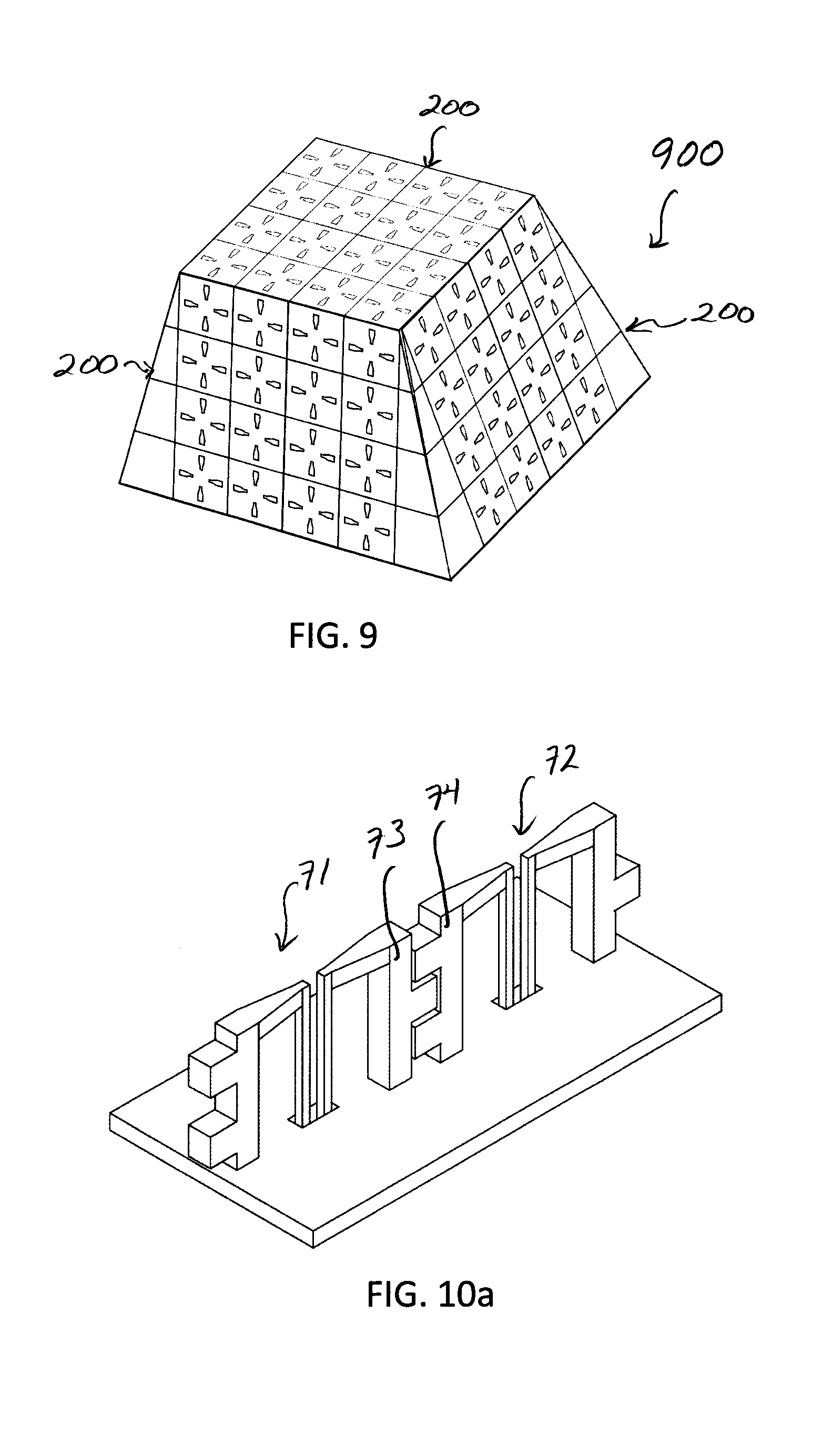
FIG. 9 schematically illustrates a three-dimensional array comprising multiple two-dimensional arrays of the present invention, such as the arrays of FIGS. 2, 7, 8; and
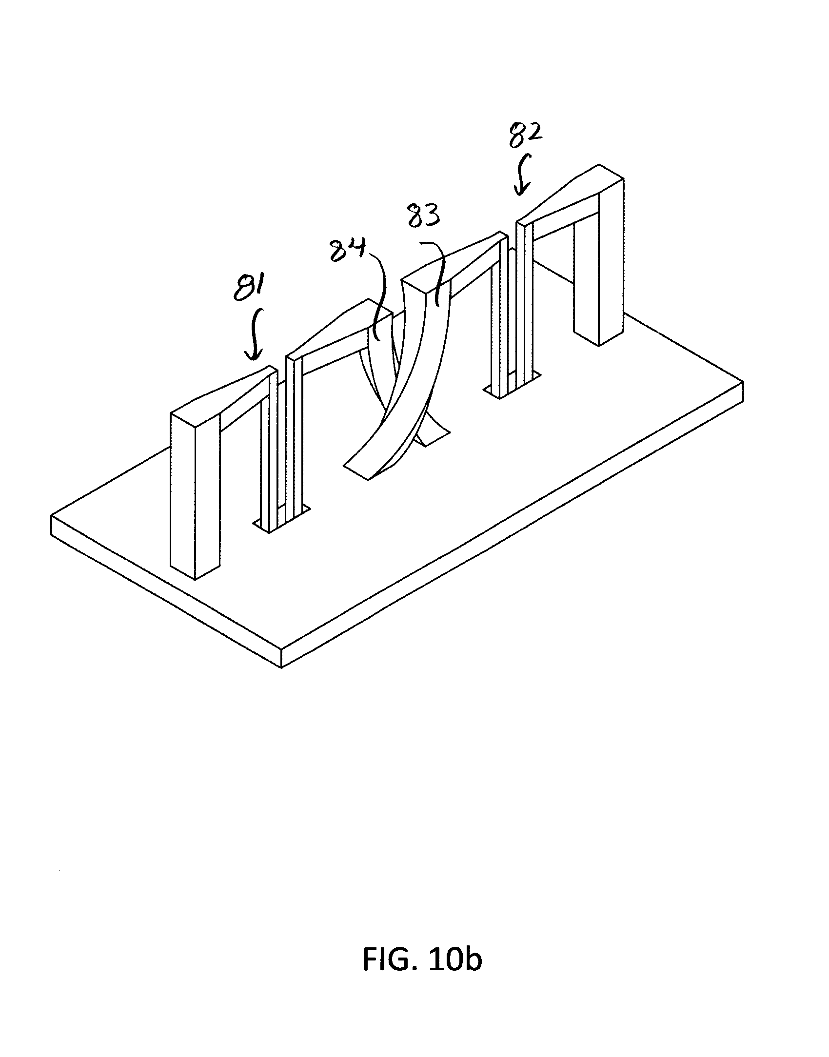
FIGS. 10a, 10b schematically illustrate coupling between the adjacent dipoles using interleaved or interwoven arms, respectively.
DETAILED DESCRIPTION OF THE INVENTION
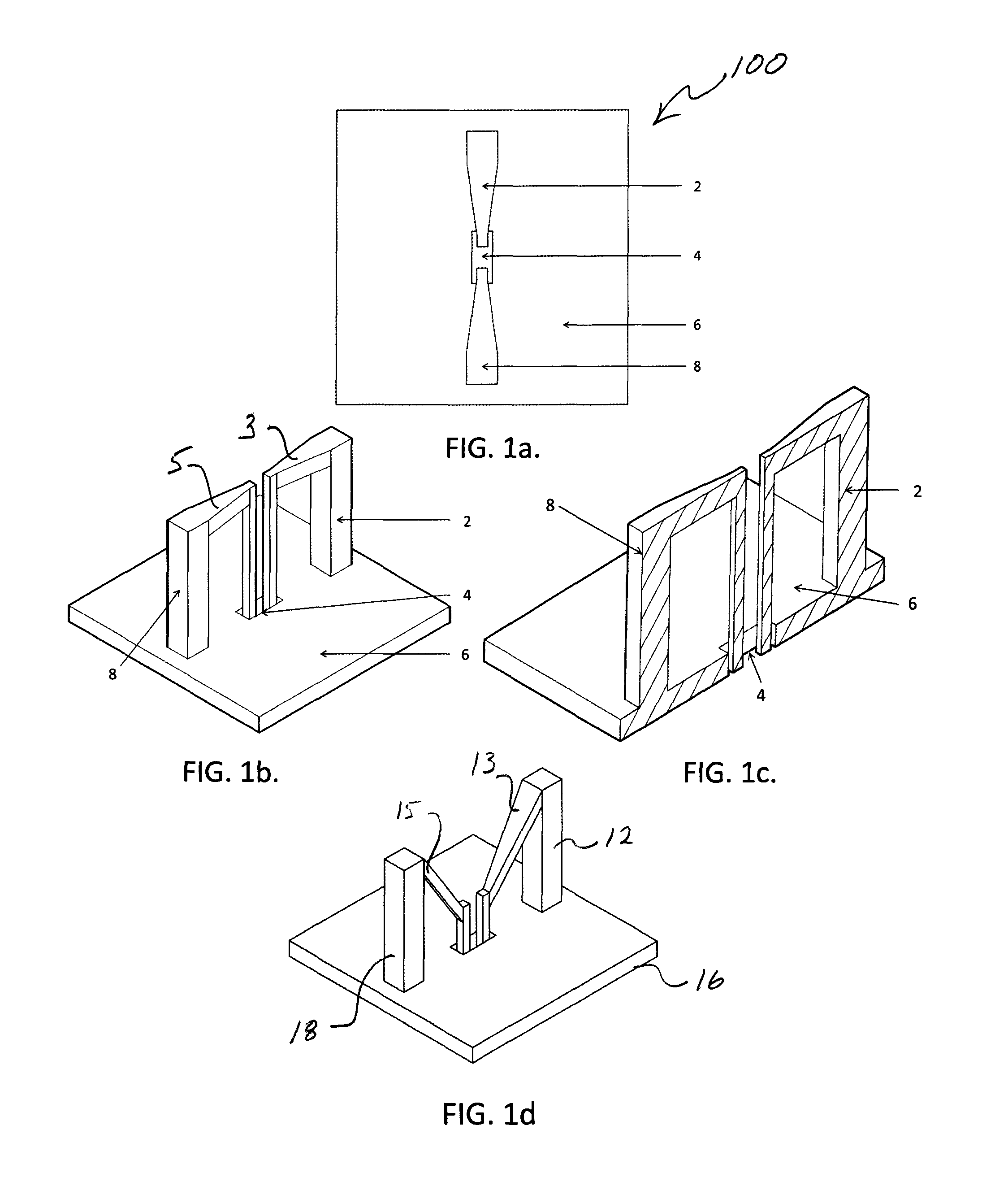
Referring now to the figures, wherein like elements are numbered alike throughout, FIGS. 1a-1c schematically illustrate an exemplary configuration of a unit cell 100 of a single-polarized antenna in accordance with the present invention. The antenna may include a differentially fed shorted arms 2, 8 of the antenna positioned above a ground surface (such as ground plane 6 or other surface shape, e.g., a conformal surface) and fed via a feed region 4, which may include one or more openings. (Though exemplary configurations of present invention may be illustrated as having a ground "plane", other surface shapes, such as conformal surfaces, may be provided for grounding.) The arms 2, 8 may cooperate to provide a dipole. The feed region 4 may be provided with no wall separating the feed points for the two differentially-fed shorted arms 2, 8. Alternatively, a wall 30 may be provided as illustrated in FIGS. 3a-3b. The arms 2, 8 may have a cross-sectional dimension that varies along the arms 2, 8 and may or may not be identical to one another. Alternatively, the arms 22, 28 may be `U`-shaped of constant cross-sectional dimension depending on the requirements of the design or to optimize performance, FIGS. 3a-3c. Still further, opposing ends of the arms 2, 8 may be of the same height above the ground plane 6 with a horizontal leg 3, 5 therebetween, FIG. 1b. Instead, the opposing ends of the arms 12, 18 may be of different height above the ground plane 16 with a sloped leg 13, 15 therebetween, FIG. 1d. This may be done for impedance matching over a greater bandwidth than what would be typical for flat precisely horizontal legs.
Similar to FIGS. 1a-1c, the structure of FIGS. 3a-3c may include a ground plane 26 and feed region 24. In addition, an array 200 of the antennas 100 of FIGS. 1a-1c (or antennas 300 of FIGS. 3a-3c) may be provided as illustrated in FIG. 2. In such as case the field generated by a dipole (i.e., pair of arms 2, 8) of the array 200 may be couple adjacent dipoles. For stronger coupling between the adjacent dipoles 71, 72, the legs 73, 74 could be interdigitated in either the vertical or horizontal direction (or both), FIG. 10a, which could be formed, for example, by the PolyStrata.RTM. process. Alternatively, the coupling between the adjacent dipoles 81, 82 may be implemented with interwoven legs 83, 84 that could be formed by 3D metal printing. Such coupling using interwoven or interleaved legs could provide additional degrees of design freedom.
The expected performance of antenna designs of the present invention is illustrated in FIGS. 4-6 for a point design that should operate from roughly 40 GHz to 120 GHz. FIG. 4 illustrates the active reflection coefficient, comparing no scanning (BS) for an element in the array to when the element is driven to 45 degrees in the e plane (E45), or 45 degrees in the h plane of the antenna (H45), or 45 degrees in both planes (D45). FIG. 5 shows the active reflection coefficient, comparing no scanning (BS) for an element in the array to when the element is driven to 60 degrees in the e plane (E60), or 60 degrees in the h plane of the antenna (H60) or 60 degrees in both planes (D60). FIG. 6 shows the active reflection coefficient, comparing no scanning (BS) for an element in the array to when the element is driven to 75 degrees in the e plane (E75), or 75 degrees in the h plane of the antenna (H75) or 75 degrees in both planes (D75).
FIG. 7c shows a two-dimensional, 4-element by 4-element array 700 of dual-polarized differentially-fed shorted dipoles. The top view of the unit cell 710 that makes up the array 700 is shown in FIG. 7a. An isometric view of the unit cell 710 of the array 700 is shown in FIG. 7b. An isometric view of a representative 4.times.4 array 700 is shown in FIG. 7c. Arms 32 and 34 make up two halves of a first differentially-fed dipole element that is fed in polarization 1. Polarization 2 is orthogonal to polarization 1 and is fed by arms 40 and 42, which make up the two halves of a second differentially-fed dipole element. The shorted dipole elements that are oriented in the same direction as 32 and 34 throughout the array 700 also feed polarization 1. This polarization means that the electric field vectors for electromagnetic waves are oriented in the same direction as the long dimension of the physical components of arms 32 and 34 that are oriented parallel to ground plane 38. A coupling gap 46 may exist in the antenna array 700 between adjacent dipoles for Polarization 1, and a coupling gap 48 may exist in the array 700 between adjacent dipoles for Polarization 2. The phase center for the orthogonal polarizations associated with each unit cell is in the same location, because arms 32, 34 and arms 40, 42 are centered about the feed region, 36. Aperture 44 is the feed aperture for arm 34, but the whole feed region 36 could be a single aperture that allows all of the feeds from arms 32, 34, 40, 42 to pass through if the dimensions are too small to allow walls to exist between individual the dipole feeds.
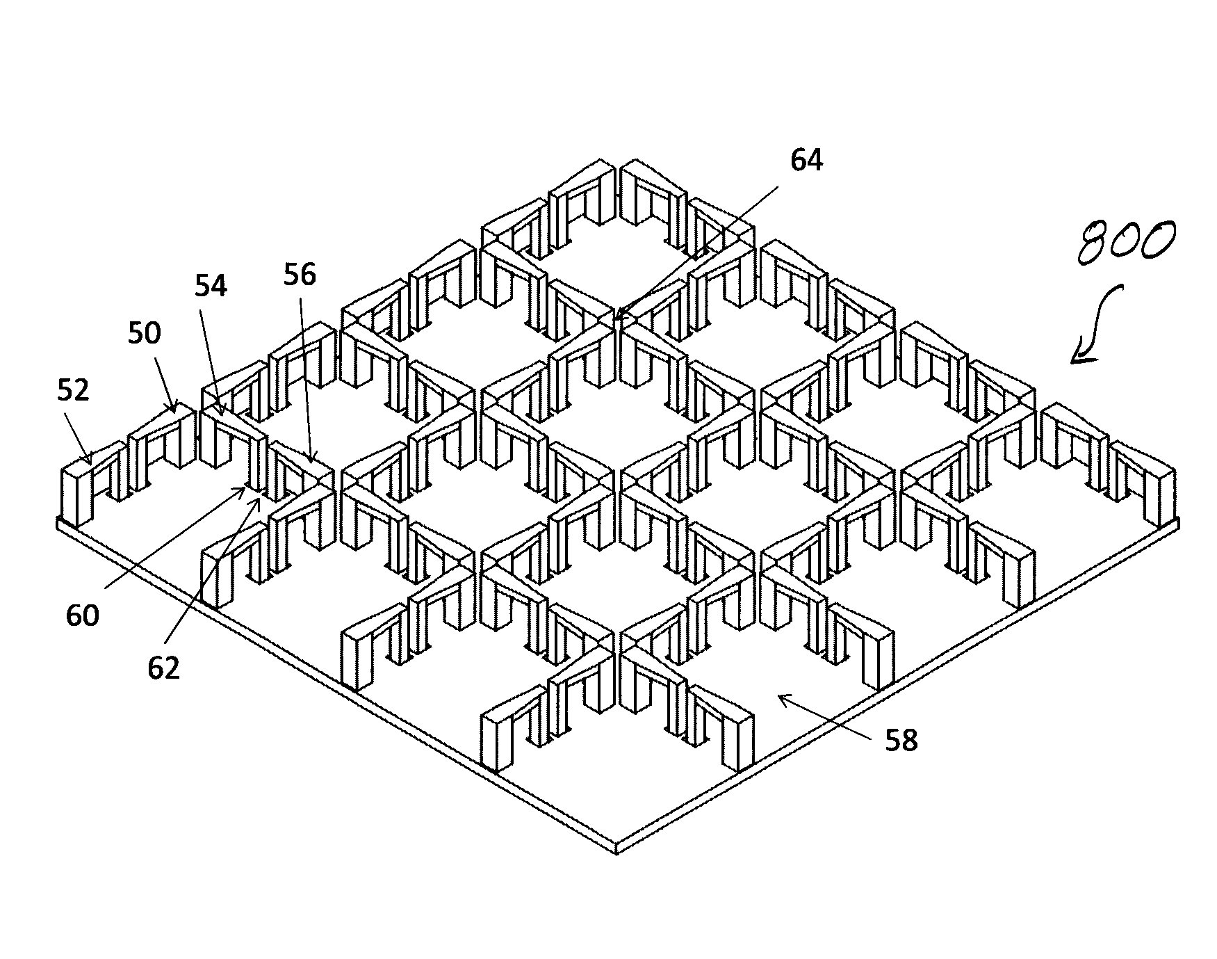
FIG. 8c shows a two-dimensional, 4-element by 4-element array 800 of dual-polarized differentially-fed shorted dipoles. The top view of the unit cell 810 that makes up the array 800 is shown in FIG. 8a. An isometric view of the unit cell 810 of the array 800 is shown in FIG. 8b. An isometric view of a representative 4.times.4 array 800 is shown in FIG. 8c. Arms 50, 52 make up two halves of a differentially-fed dipole element that is fed in polarization 1. Polarization 2 is orthogonal to polarization 1 and is fed by arms 54, 56, which make up the two halves of a second differentially-fed dipole element. The shorted dipole elements that are oriented in the same direction as arms 50, 52 throughout the array 800 also feed polarization 1. This polarization means that the electric field vectors for electromagnetic waves are oriented in the same direction as the physical components of arms 50, 52 that are oriented parallel to ground plane 58. A coupling gap 64 may exist between the adjacent dipoles for both polarizations. These coupling gaps 64 could be simple, as shown in the drawing, or they could be interdigitated in such a way as to selectively couple between adjacent dipoles for a given polarization, FIGS. 10a, 10b. The phase center for each polarization is centered between the two dipole arms associated with said polarization and the two phase centers for each polarization are offset with respect to the other. Aperture 60 is a feed region for the differentially shorted dipole arms 54, 56. A separation wall 62 may or may not exist between the arms 54, 56. One may choose to use offset orthogonal elements, as shown in FIGS. 8a-8c, to make it easier to place the beam-forming electronics behind the array.
These and other advantages of the present invention will be apparent to those skilled in the art from the foregoing specification. For instance, a plurality of two-dimensional arrays, such as the arrays 200, 700, 800, may be combined to provide a three-dimensional array 900, FIG. 9. Accordingly, it will be recognized by those skilled in the art that changes or modifications may be made to the above-described embodiments without departing from the broad inventive concepts of the invention. It should therefore be understood that this invention is not limited to the particular embodiments described herein, but is intended to include all changes and modifications that are within the scope and spirit of the invention as set forth in the claims.
* * * * *
D00000
D00001
D00002
D00003
D00004
D00005
D00006
D00007
D00008
D00009
D00010
XML
uspto.report is an independent third-party trademark research tool that is not affiliated, endorsed, or sponsored by the United States Patent and Trademark Office (USPTO) or any other governmental organization. The information provided by uspto.report is based on publicly available data at the time of writing and is intended for informational purposes only.
While we strive to provide accurate and up-to-date information, we do not guarantee the accuracy, completeness, reliability, or suitability of the information displayed on this site. The use of this site is at your own risk. Any reliance you place on such information is therefore strictly at your own risk.
All official trademark data, including owner information, should be verified by visiting the official USPTO website at www.uspto.gov. This site is not intended to replace professional legal advice and should not be used as a substitute for consulting with a legal professional who is knowledgeable about trademark law.