Matching geometry generation and display of mammograms and tomosynthesis images
Ren , et al.
U.S. patent number 10,248,882 [Application Number 15/804,915] was granted by the patent office on 2019-04-02 for matching geometry generation and display of mammograms and tomosynthesis images. This patent grant is currently assigned to Hologic, Inc.. The grantee listed for this patent is Hologic, Inc.. Invention is credited to Baorui Ren, Christopher Ruth, Andrew P. Smith, Jay A. Stein, Kevin Wilson.
| United States Patent | 10,248,882 |
| Ren , et al. | April 2, 2019 |
Matching geometry generation and display of mammograms and tomosynthesis images
Abstract
A method and a system for using tomosynthesis projection images of a patient's breast to reconstruct slice tomosynthesis images such that anatomical structures that appear superimposed in a mammogram are at conforming locations in the reconstructed images.
| Inventors: | Ren; Baorui (Andover, MA), Ruth; Christopher (Boxford, MA), Smith; Andrew P. (Lexington, MA), Wilson; Kevin (Waltham, MA), Stein; Jay A. (Boston, MA) | ||||||||||
|---|---|---|---|---|---|---|---|---|---|---|---|
| Applicant: |
|
||||||||||
| Assignee: | Hologic, Inc. (Marlborough,
MA) |
||||||||||
| Family ID: | 36407794 | ||||||||||
| Appl. No.: | 15/804,915 | ||||||||||
| Filed: | November 6, 2017 |
Prior Publication Data
| Document Identifier | Publication Date | |
|---|---|---|
| US 20180137385 A1 | May 17, 2018 | |
Related U.S. Patent Documents
| Application Number | Filing Date | Patent Number | Issue Date | ||
|---|---|---|---|---|---|
| 14744930 | Jun 19, 2015 | 9811758 | |||
| 14263216 | Jul 21, 2015 | 9084579 | |||
| 13418851 | Apr 29, 2014 | 8712127 | |||
| 12535343 | Apr 10, 2012 | 8155421 | |||
| 11667650 | Apr 10, 2010 | 7702142 | |||
| PCT/US2005/041941 | Nov 15, 2005 | ||||
| 60628516 | Nov 15, 2004 | ||||
| Current U.S. Class: | 1/1 |
| Current CPC Class: | G06T 11/60 (20130101); A61B 6/502 (20130101); G06K 9/6201 (20130101); G06T 3/0006 (20130101); G06T 11/006 (20130101); G06T 7/30 (20170101); G06T 2207/30068 (20130101); G06T 2207/10081 (20130101) |
| Current International Class: | G06T 3/00 (20060101); G06K 9/62 (20060101); G06T 11/00 (20060101); A61B 6/00 (20060101); G06T 11/60 (20060101); G06T 7/30 (20170101) |
References Cited [Referenced By]
U.S. Patent Documents
| 3502878 | March 1970 | Stewart |
| 3863073 | January 1975 | Wagner |
| 3971950 | July 1976 | Evans et al. |
| 4160906 | July 1979 | Daniels et al. |
| 4310766 | January 1982 | Finkenzeller et al. |
| 4496557 | January 1985 | Malen et al. |
| 4559641 | December 1985 | Caugant et al. |
| 4706269 | November 1987 | Reina et al. |
| 4744099 | May 1988 | Huettenrauch et al. |
| 4773086 | September 1988 | Fujita et al. |
| 4773087 | September 1988 | Plewes |
| 4819258 | April 1989 | Kleinman et al. |
| 4821727 | April 1989 | Levene et al. |
| 4969174 | November 1990 | Scheid et al. |
| 4989227 | January 1991 | Tirelli et al. |
| 5018176 | May 1991 | Romeas et al. |
| RE33634 | July 1991 | Yanaki |
| 5029193 | July 1991 | Saffer |
| 5051904 | September 1991 | Griffith |
| 5078142 | January 1992 | Siczek et al. |
| 5163075 | November 1992 | Lubinsky et al. |
| 5164976 | November 1992 | Scheid et al. |
| 5199056 | March 1993 | Darrah |
| 5240011 | August 1993 | Assa |
| 5289520 | February 1994 | Pellegrino et al. |
| 5359637 | October 1994 | Webbe |
| 5365562 | November 1994 | Toker |
| 5415169 | May 1995 | Siczek et al. |
| 5426685 | June 1995 | Pellegrino et al. |
| 5452367 | September 1995 | Bick et al. |
| 5506877 | April 1996 | Niklason et al. |
| 5526394 | June 1996 | Siczek et al. |
| 5539797 | July 1996 | Heidsieck et al. |
| 5553111 | September 1996 | Moore et al. |
| 5592562 | January 1997 | Rooks |
| 5594769 | January 1997 | Pellegrino et al. |
| 5596200 | January 1997 | Sharma et al. |
| 5598454 | January 1997 | Franetzki et al. |
| 5609152 | March 1997 | Pellegrino et al. |
| 5627869 | May 1997 | Andrew et al. |
| 5657362 | August 1997 | Giger et al. |
| 5668889 | September 1997 | Hara |
| 5719952 | February 1998 | Rooks |
| 5735264 | April 1998 | Siczek et al. |
| 5769086 | June 1998 | Ritchart et al. |
| 5803912 | September 1998 | Siczek et al. |
| 5818898 | October 1998 | Tsukamoto et al. |
| 5828722 | October 1998 | Ploetz et al. |
| 5872828 | February 1999 | Niklason et al. |
| 5878104 | March 1999 | Ploetz |
| 5896437 | April 1999 | Ploetz |
| 5986662 | November 1999 | Argiro et al. |
| 6005907 | December 1999 | Ploetz |
| 6022325 | February 2000 | Siczek et al. |
| 6075879 | June 2000 | Roehrig et al. |
| 6091841 | July 2000 | Rogers et al. |
| 6137527 | October 2000 | Abdel-Malek et al. |
| 6141398 | October 2000 | He et al. |
| 6149301 | November 2000 | Kautzer et al. |
| 6175117 | January 2001 | Komardin et al. |
| 6196715 | March 2001 | Nambu et al. |
| 6216540 | April 2001 | Nelson et al. |
| 6219059 | April 2001 | Argiro |
| 6233473 | May 2001 | Shepherd et al. |
| 6243441 | June 2001 | Zur |
| 6256370 | July 2001 | Yavuz |
| 6272207 | August 2001 | Tang |
| 6289235 | September 2001 | Webber et al. |
| 6292530 | September 2001 | Yavus et al. |
| 6327336 | December 2001 | Gingold et al. |
| 6341156 | January 2002 | Baetz et al. |
| 6375352 | April 2002 | Hewes et al. |
| 6411836 | June 2002 | Patel et al. |
| 6415015 | July 2002 | Nicolas et al. |
| 6442288 | August 2002 | Haerer et al. |
| 6459925 | October 2002 | Nields et al. |
| 6501819 | December 2002 | Unger et al. |
| 6556655 | April 2003 | Chichereau et al. |
| 6597762 | July 2003 | Ferrant et al. |
| 6611575 | August 2003 | Alyassin et al. |
| 6620111 | September 2003 | Stephens et al. |
| 6626849 | September 2003 | Huitema et al. |
| 6633674 | October 2003 | Barnes et al. |
| 6638235 | October 2003 | Miller et al. |
| 6647092 | November 2003 | Eberhard et al. |
| 6744848 | June 2004 | Stanton et al. |
| 6748044 | June 2004 | Sabol et al. |
| 6751285 | June 2004 | Eberhard et al. |
| 6758824 | July 2004 | Miller et al. |
| 6813334 | November 2004 | Koppe et al. |
| 6882700 | April 2005 | Wang et al. |
| 6885724 | April 2005 | Li et al. |
| 6912319 | June 2005 | Barnes et al. |
| 6940943 | September 2005 | Claus et al. |
| 6978040 | December 2005 | Berestov |
| 6999554 | February 2006 | Mertelmeier |
| 7025725 | April 2006 | Dione et al. |
| 7110490 | September 2006 | Eberhard |
| 7110502 | September 2006 | Tsuji |
| 7123684 | October 2006 | Jing et al. |
| 7127091 | October 2006 | Op De Beek et al. |
| 7142633 | November 2006 | Eberhard et al. |
| 7245694 | July 2007 | Jing et al. |
| 7315607 | January 2008 | Ramsauer |
| 7319735 | January 2008 | Defreitas et al. |
| 7323692 | January 2008 | Rowlands et al. |
| 7430272 | September 2008 | Jing et al. |
| 7443949 | October 2008 | Defreitas et al. |
| 7630533 | December 2009 | Ruth et al. |
| 7702142 | April 2010 | Ren |
| 8712127 | April 2014 | Ren et al. |
| 9084579 | July 2015 | Ren |
| 9811758 | November 2017 | Ren |
| 2001/0038681 | November 2001 | Stanton et al. |
| 2001/0038861 | November 2001 | Hsu et al. |
| 2002/0012450 | January 2002 | Tsujii |
| 2002/0050986 | May 2002 | Inoue et al. |
| 2002/0075997 | June 2002 | Unger et al. |
| 2003/0018272 | January 2003 | Treado et al. |
| 2003/0073895 | April 2003 | Nields et al. |
| 2003/0095624 | May 2003 | Eberhard et al. |
| 2003/0194050 | October 2003 | Eberhard et al. |
| 2003/0194051 | October 2003 | Wang et al. |
| 2003/0194121 | October 2003 | Eberhard et al. |
| 2003/0210254 | November 2003 | Doan et al. |
| 2003/0215120 | November 2003 | Uppaluri et al. |
| 2004/0008809 | January 2004 | Webber |
| 2004/0066882 | April 2004 | Eberhard et al. |
| 2004/0066884 | April 2004 | Hermann Claus et al. |
| 2004/0066904 | April 2004 | Eberhard et al. |
| 2004/0094167 | May 2004 | Brady et al. |
| 2004/0101095 | May 2004 | Jing et al. |
| 2004/0109529 | June 2004 | Eberhard et al. |
| 2004/0171986 | September 2004 | Tremaglio, Jr. et al. |
| 2004/0267157 | December 2004 | Miller et al. |
| 2005/0049521 | March 2005 | Miller et al. |
| 2005/0063509 | March 2005 | Defreitas et al. |
| 2005/0078797 | April 2005 | Danielsson et al. |
| 2005/0105679 | May 2005 | Wu et al. |
| 2005/0113681 | May 2005 | DeFreitas |
| 2005/0113715 | May 2005 | Schwindt et al. |
| 2005/0129172 | June 2005 | Mertelmeier |
| 2005/0135555 | June 2005 | Claus et al. |
| 2005/0135664 | June 2005 | Kaufhold et al. |
| 2005/0226375 | October 2005 | Eberhard et al. |
| 2006/0030784 | February 2006 | Miller et al. |
| 2006/0074288 | April 2006 | Kelly et al. |
| 2006/0098855 | May 2006 | Gkanatsios et al. |
| 2006/0129062 | June 2006 | Nicoson et al. |
| 2006/0155209 | July 2006 | Miller et al. |
| 2006/0291618 | December 2006 | Eberhard et al. |
| 2007/0030949 | February 2007 | Jing et al. |
| 2007/0036265 | February 2007 | Jing et al. |
| 2007/0076844 | April 2007 | Defreitas et al. |
| 2007/0223651 | September 2007 | Wagenaar et al. |
| 2007/0225600 | September 2007 | Weibrecht et al. |
| 2007/0242800 | October 2007 | Jing et al. |
| 2008/0019581 | January 2008 | Gkanatsios et al. |
| 2008/0045833 | February 2008 | Defreitas et al. |
| 2008/0130979 | June 2008 | Ren et al. |
| 2009/0003519 | January 2009 | Defreitas et al. |
| 2009/0010384 | January 2009 | Jing et al. |
| 2009/0080594 | March 2009 | Brooks et al. |
| 2009/0080602 | March 2009 | Brooks et al. |
| 2009/0135997 | May 2009 | Defreitas et al. |
| 2009/0268865 | October 2009 | Ren et al. |
| 2009/0296882 | December 2009 | Gkanatsios et al. |
| 2009/0304147 | December 2009 | Jing et al. |
| 2010/0054400 | March 2010 | Ren et al. |
| 2010/0086188 | April 2010 | Ruth et al. |
| 2010/0135558 | June 2010 | Ruth et al. |
| 2010/0195882 | August 2010 | Ren et al. |
| 2010/0226475 | September 2010 | Smith et al. |
| 775467 | May 1997 | EP | |||
| 982001 | Mar 2000 | EP | |||
| 1428473 | Jun 2004 | EP | |||
| WO 90/05485 | May 1990 | WO | |||
| WO 98/16903 | Apr 1998 | WO | |||
| WO 00/51484 | Sep 2000 | WO | |||
| WO 03/020114 | Mar 2003 | WO | |||
| WO 2005/051197 | Jun 2005 | WO | |||
| WO 2005110230 | Nov 2005 | WO | |||
| WO 2005 112767 | Dec 2005 | WO | |||
| WO 2006/055830 | May 2006 | WO | |||
| WO 2006/058160 | Jun 2006 | WO | |||
Other References
|
Cole, Elodia, et al., "The Effects of Gray Seale Image Processing on Digital Mammography Interpretation Performance", Academic Radiology, vol. 12, No. 5, pp. 585-595, May 2005. cited by applicant . Digital Clinical Reports, Tomosynthesis, GE Brochure 98/5493, Nov. 1998. cited by applicant . Dobbins JT et al. "Digital x-ray tomosynthesis: current state of the art and clinical potential" Physics in Medicine and Biology vol. 48, No. 19, pp. 65-81 (2003). cited by applicant . Essentials for life: Senographe Essential Full-Field Digital Mammography System, GE Health-care Brochure, MM-0132-05.06-ENUS, 2006. cited by applicant . European search report in connection with corresponding European patent application No. EP 06 25 5790, dated Aug. 17, 2007. cited by applicant . European search report in connection with counterpart European Patent Application No. 05824734, dated May 9, 2011. cited by applicant . Filtered Back Projection, (Nygren) published May 8, 2007; URL: http://web.archive.org/web/1999101013 I 715/http://www.owlnet.rice.edu/-elec539/Projects97/cult/node2.html. cited by applicant . Grant, DG, "Tomosynthesis, a three dimensional imagine technique", IEEE Trans. Biomed Engineering, vol. BME-19, #1, Jan. 1972, pp. 20-28. cited by applicant . Heang-Ping Chan et al., "ROC study of the effect of stereoscopic imaging on assessment of breast lesions", Medical Physics, vol. 32, No. 4, Apr. 2005. cited by applicant . Kita et al., "Correspondence between different view breast X-rays using simulation of breast deformation", Proceedings 1998 IEE Computer Society Conference on Computer Vision and Pattern Recognition, Santa Barbara, CA, Jun. 23-25, 1998, pp. 700-707. cited by applicant . Lorad Selenia Document B-BI-SEO US/Intl (May 2006) copyright Hologic 2006. cited by applicant . Mammographic Accreditation Phantom, http://www.cirsinc.com/pdfs/015cp.pdf. cited by applicant . PCT International Search Report and Written Opinion in International Application PCT/US2005/041941, dated Sep. 25, 2008, 6 pgs. cited by applicant . Pediconi, Federica et al., "Color-coded automated signal intensity curve for detection and characterization of breast lesions: Preliminary evaluation of a new software for MR-based breast imaging", International Congress Series 1281 (2005) 1081-1086. cited by applicant . Senographe 700 & 8OOT (GE); 2-page download on Jun. 22, 2006 from www.gehealthcare.com/inen/rad/whe/products/mswh800t.html.; Figures 1-7 on 4 sheets relateral shift compression paddle. cited by applicant . Smith, A., "Fundamentals of Breast Tomosynthesis", White Paper, Hologic Inc., WP-00007, Jun. 2008. cited by applicant. |
Primary Examiner: Bayat; Ali
Parent Case Text
CROSS REFERENCE TO RELATED APPLICATIONS
This application is a continuation of U.S. patent application Ser. No. 14/744,930, filed Jun. 19, 2015, now U.S. Pat. No. 9,811,758, which is a continuation of U.S. patent application Ser. No. 14/263,216, filed Apr. 18, 2014, now U.S. Pat. No. 9,084,579, which is a continuation of U.S. patent application Ser. No. 13/418,851, filed Mar. 13, 2012, now U.S. Pat. No. 8,712,127, which is a continuation of U.S. patent application Ser. No. 12/535,343, filed Aug. 4, 2009, now U.S. Pat. No. 8,155,421, which is a continuation of U.S. patent application Ser. No. 11/667,650, filed Nov. 30, 2007, now U.S. Pat. No. 7,702,142, which is a National Stage Application of PCT/US200541941 filed Nov. 15, 2005, which claims priority to and the benefit of U.S. Provisional Patent Application No. 60/628,516, filed Nov. 15, 2004, the disclosures of which are hereby incorporated by reference herein in their entireties.
Claims
The invention claimed is:
1. A method comprising: imaging a breast so as to acquire digital information corresponding to a plurality of x-ray tomosynthesis projection images of the breast taken at different angles; generating, from the digital information, a plurality of reconstructed tomosynthesis images representative of respective breast layers; obtaining a mammogram image of the breast; receiving a selection of a region of interest in the mammogram image of the breast; and displaying a portion of at least one of the plurality of reconstructed tomosynthesis images corresponding to the selected region of interest.
2. The method of claim 1, further comprising displaying a portion of the mammogram image of the breast.
3. The method of claim 2, further comprising simultaneously: displaying the portion of the mammogram image; and displaying the portion of the at least one of the plurality of reconstructed tomosynthesis images.
4. The method of claim 3, wherein the portion of the at least one of the plurality of reconstructed tomosynthesis images is displayed within the selected region of interest.
5. The method of claim 4, further comprising: receiving an input; and in response to the received input, displaying sequentially at least a portion of each of at least two of the plurality of reconstructed tomosynthesis images.
6. The method of claim 5, wherein the at least a portion of each of at least two of the plurality of reconstructed tomosynthesis images are displayed within the selected region of interest.
7. The method of claim 1, wherein each of the plurality of reconstructed tomosynthesis images are parallel to an image plane of the mammogram image of the breast.
8. The method of claim 1, wherein the obtaining operation comprises directing an x-ray at the breast.
9. The method of claim 1, wherein each of the plurality of reconstructed tomosynthesis images is representative of respective breast layers and has a layer thickness corresponding to a thickness of a breast that is less than a total thickness of the breast.
10. The method of claim 1, wherein the selection of the region of interest comprises a drawing of a region of interest.
11. A method comprising: displaying a mammogram image of a compressed breast, wherein the mammogram image corresponds to substantially an entire thickness of the compressed breast; receiving an input corresponding to a region of interest in the mammogram image; displaying, within the region of interest, at least a portion of a first reconstructed tomosynthesis image, wherein the first reconstructed tomosynthesis image corresponds to less than substantially the entire thickness of the compressed breast.
12. The method of claim 11, further comprising displaying at least a portion of the mammogram image.
13. The method of claim 12, wherein the a portion of the mammogram image within the region of interest is not displayed.
14. The method of claim 13, further comprising receiving an input and, based at least in part on the input, displaying sequentially the portion of first reconstructed tomosynthesis image and a portion of a second reconstructed tomosynthesis image.
15. The method of claim 14, further comprising: receiving a marker input when the first reconstructed tomosynthesis image is displayed; and displaying the marker on the first reconstructed tomosynthesis image.
16. The method of claim 15, further comprising displaying the marker on the second reconstructed tomosynthesis image.
17. The method of claim 15, wherein the marker corresponds to a location of a suspected abnormality.
18. The method of claim 11, wherein the first reconstructed tomosynthesis image corresponds to a first reconstructed tomosynthesis image plane that is substantially parallel to a mammogram image plane.
19. The method of claim 11, further comprising obtaining the mammogram image and the first reconstructed tomosynthesis image.
20. The method of claim 19, wherein at least one of the mammogram image and the first reconstructed tomosynthesis image is obtained by directing x-rays at the compressed breast.
Description
FIELD
This patent specification is in the field of x-ray imaging of patients for screening or other purposes, and more specifically is directed to methods and systems for generating and displaying mammograms and tomosynthesis x-ray images in ways that improve their usefulness.
BACKGROUND
Breast cancer remains a significant threat to women's health. X-ray mammograms have long been a standard in screening patients for breast cancer or other abnormalities and also are widely used in diagnosis and treatment planning. X-ray mammography typically records the breast image on x-ray film but more recently digital x-ray image receptors have come into use, as in the Selenia.TM. mammography system available from Hologic Inc. of Bedford, Mass. and its division Lorad of Danbury, Conn. For mammograms, a cone-shaped or pyramid-shaped x-ray beam passes through the compressed breast and forms a two-dimensional projection image. Any one of a number of orientations can be used, such as cranial-caudal (CC) or MLO (mediolateral-oblique) orientation. More recently, breast x-ray tomosynthesis has been proposed. The technology typically involves taking two-dimensional (2D) projection images of the immobilized breast at each of a number of angles of the x-ray beam relative to the breast and processing the resulting x-ray measurements to reconstruct images of breast slices that typically are in planes transverse to the x-ray beam axis, such as parallel to the image plane of a mammogram of the same breast. The range of angles is substantially less than in computerized tomography, i.e. substantially less than 180.degree., e.g. .+-.15.degree.. Tomosynthesis technology is described in U.S. patent application Ser. No. 10/723,486 filed Nov. 26, 2003; a prototype of a unit with at least some of the described features was shown at the 2003 Radiological Society of North America meeting in Chicago, Ill. Additional prototypes are in clinical testing in this country as of the filing of this patent specification. Other approaches to tomosynthesis also have been proposed: see, e.g., U.S. Pat. Nos. 4,496,557, 5,051,904, 5,359,637, 6,289.235, and 6,647,092, published U.S. Patent Applications Nos. 2001/0038861, 2004/066882, 2004/0066884, and 2004/0066904, and Digital Clinical Reports, Tomosynthesis (GE Brochure 98-5493, November 1998). How to reconstruct tomosynthesis images is discussed in DG Grant, "Tomosynthesis: a three-dimensional imaging technique", IEEE Trans. Biomed. Engineering, Vol BME-19, #1, (January 1972), pp 20-28. The patents, applications, brochures, and article cited above are hereby incorporated by reference in this patent specification as though fully set forth herein.
In clinical use, it can be desirable for a number of reasons to assess both tomosynthesis images and conventional mammograms of the patient's breasts. For example, the decades of conventional mammograms have enabled medical professionals to develop valuable interpretation expertise. Mammograms may offer good visualization of microcalcifications, and can otter higher spatial resolution compared with tomosynthesis. Tomosynthesis images may have different desirable characteristics--e.g., they may offer better visualization of structures that can be obscured by overlying or underlying tissue in a conventional mammogram. However, the inventors named herein have recognized that a challenge arises in assessing tomosynthesis images, either alone or in conjunction with mammograms of the same breast. Tomosynthesis images tend to look different from mammograms in that a given tomosynthesis image may not show anatomical structure seen in a mammogram or in another tomosynthesis image of the same breast; and, to the extent a tomosynthesis image shows structure that also is seen in the mammogram or in another tomosynthesis image, that structure may be at different relative places in the images. This can make it difficult to apply to tomosynthesis images the expertise built over years of experience reading mammograms, and difficult to visualize and assess the same structure from the different types of images. For these and other reasons, the inventors believe that a need exists for further improvements in the generation and presentation of such images to make them more useful to health professionals.
SUMMARY
The disclosed process and system generate and display tomosynthesis slice images of a patient's breast such that an object in the breast is at same or at least matching relative places in each slice image in which it is visible and, preferably, also at the same or at least matching place as in a conventional mammogram of the same breast. To achieve this, the method and system obtain 2D x-ray projection data for tomosynthesis images and, preferably, at least one 2D x-ray projection mammogram of a patient's breast, preferably using in each case a cone-shaped or pyramid-shaped imaging x-ray beam, and generate tomosynthesis images such that they conform to the same geometric coordinate system and, preferably, to the same coordinate system as a 2D projection mammogram. As a result, anatomical structures appear at geometrically matching or corresponding places in such tomosynthesis images and, preferably, in the mammogram. The tomosynthesis images can be generated in a two-step computer-implemented process that tirst reconstructs tomosynthesis images in an initial coordinate system in which objects are not or may not be at matching positions in different tomosynthesis images or in the mammogram, and then projects those images into another coordinate system, such as the coordinate system of the mammogram. Alternatively, the reconstruction can directly generate tomosynthesis images that match the appropriate coordinate system, e.g. the cone beam geometry of the mammogram. Still alternatively, the cone-shaped or pyramid-shaped beam can be simulated by scanning the breast with a fan-shaped x-ray beam or a beam having some other geometry. The term x-ray beam as used in this patent specification includes such simulated cone-shaped or pyramid-shaped beams.
BRIEF DESCRIPTION OF THE DRAWINGS
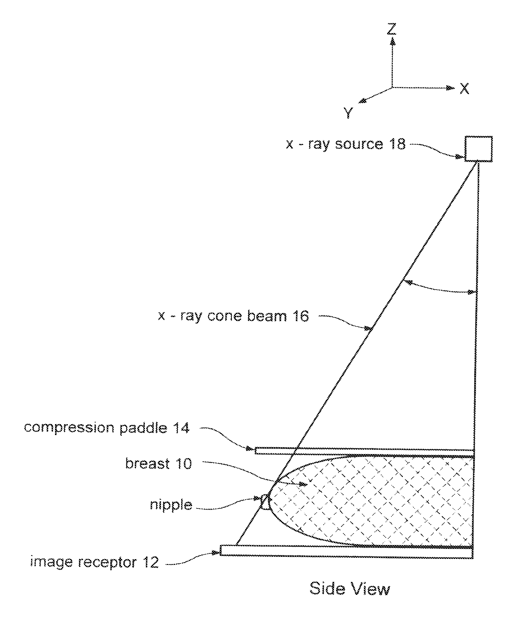
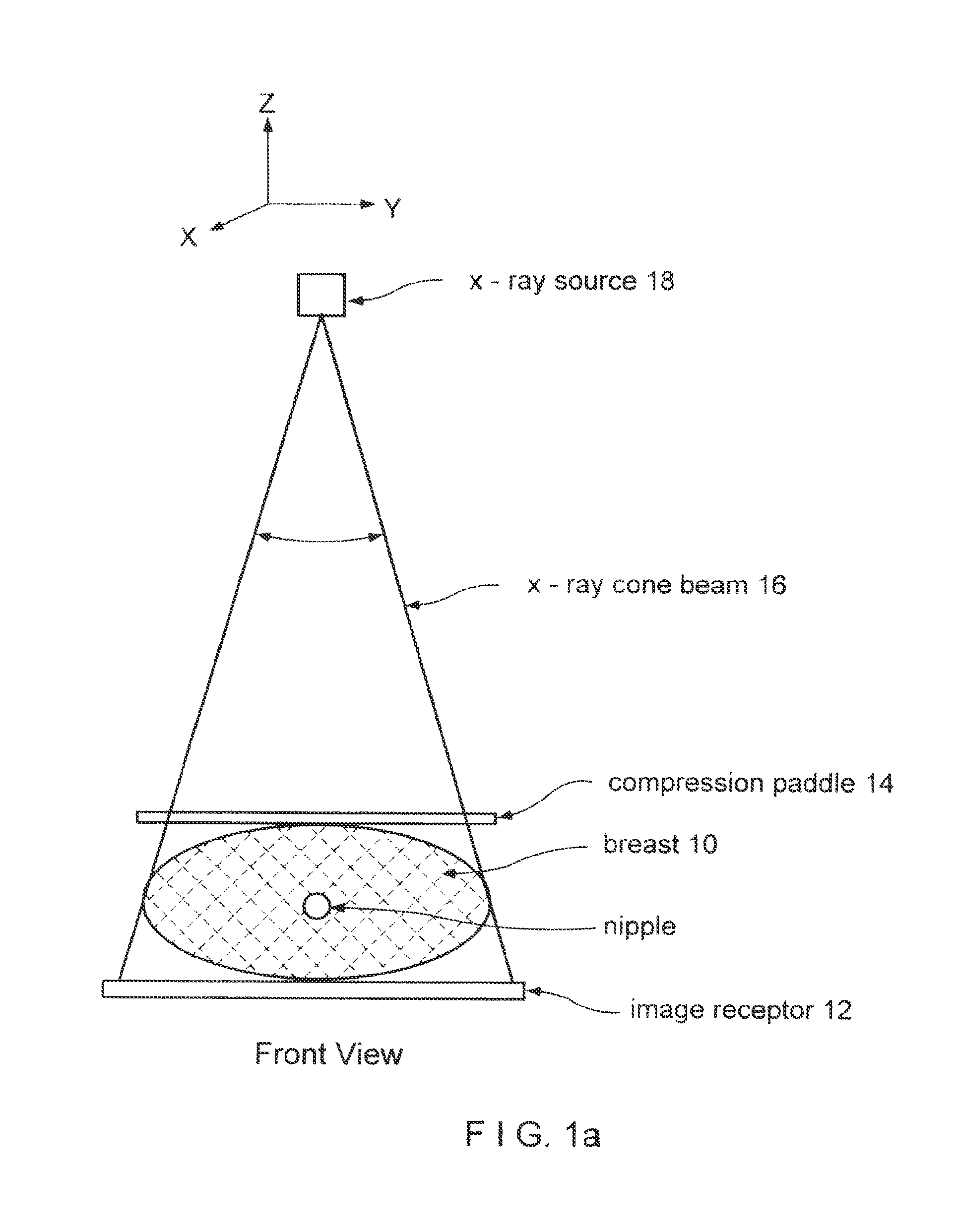
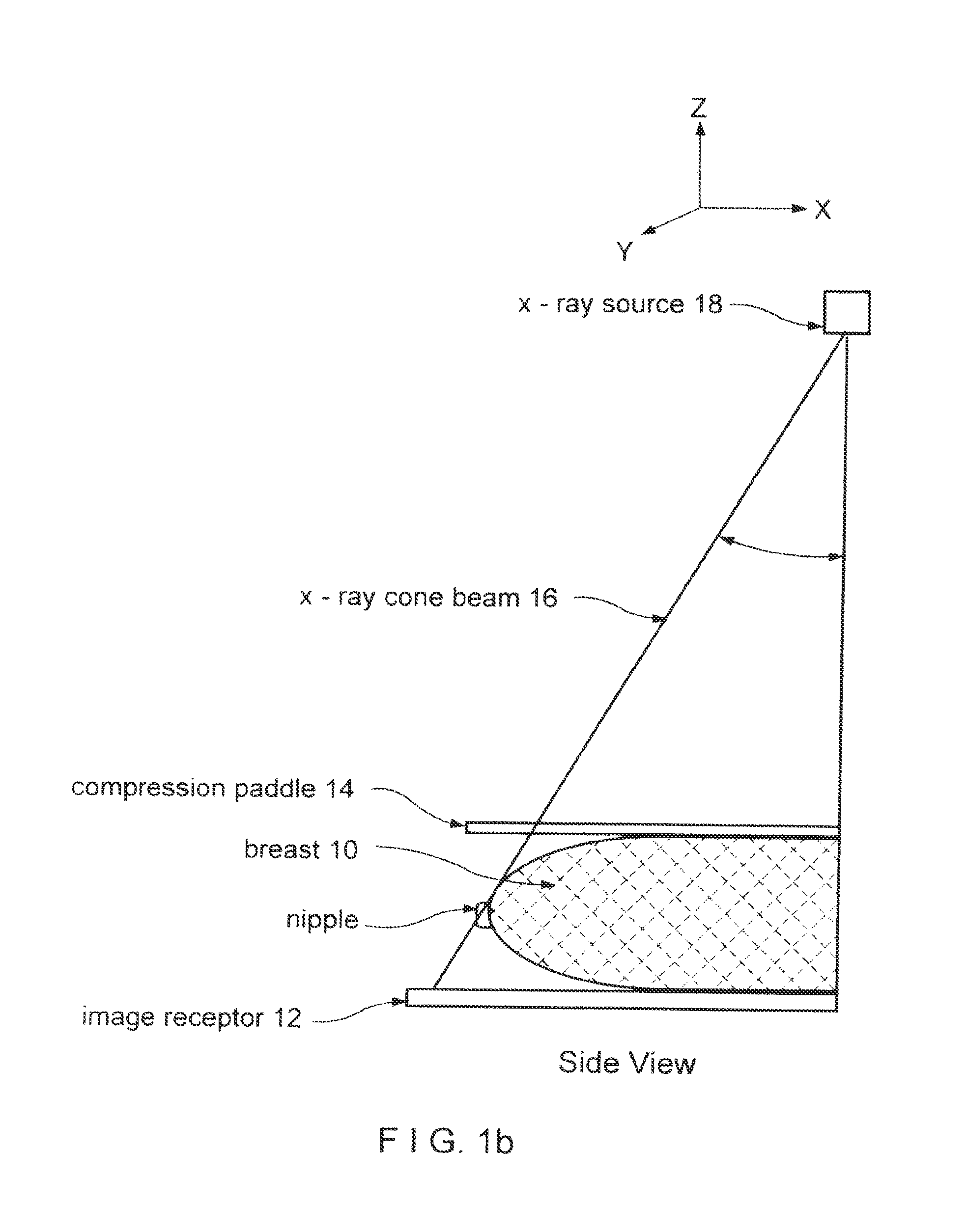
FIGS. 1a and 1b illustrate in simplified form an example of geometry used in obtaining x-ray mammograms and x-ray tomosynthesis measurements.
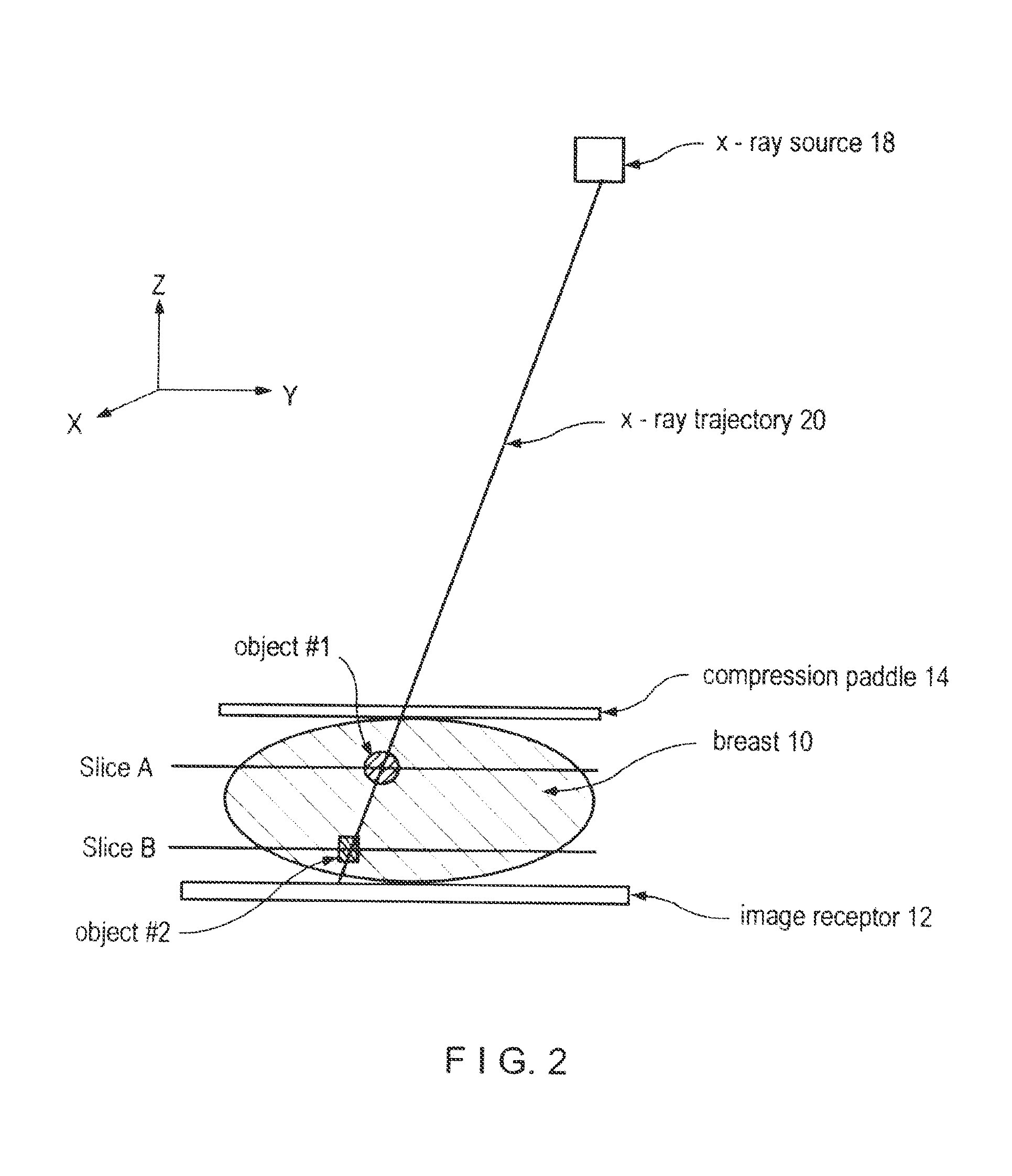
FIG. 2 illustrates image planes of a mammogram and tomosynthesis slice images.
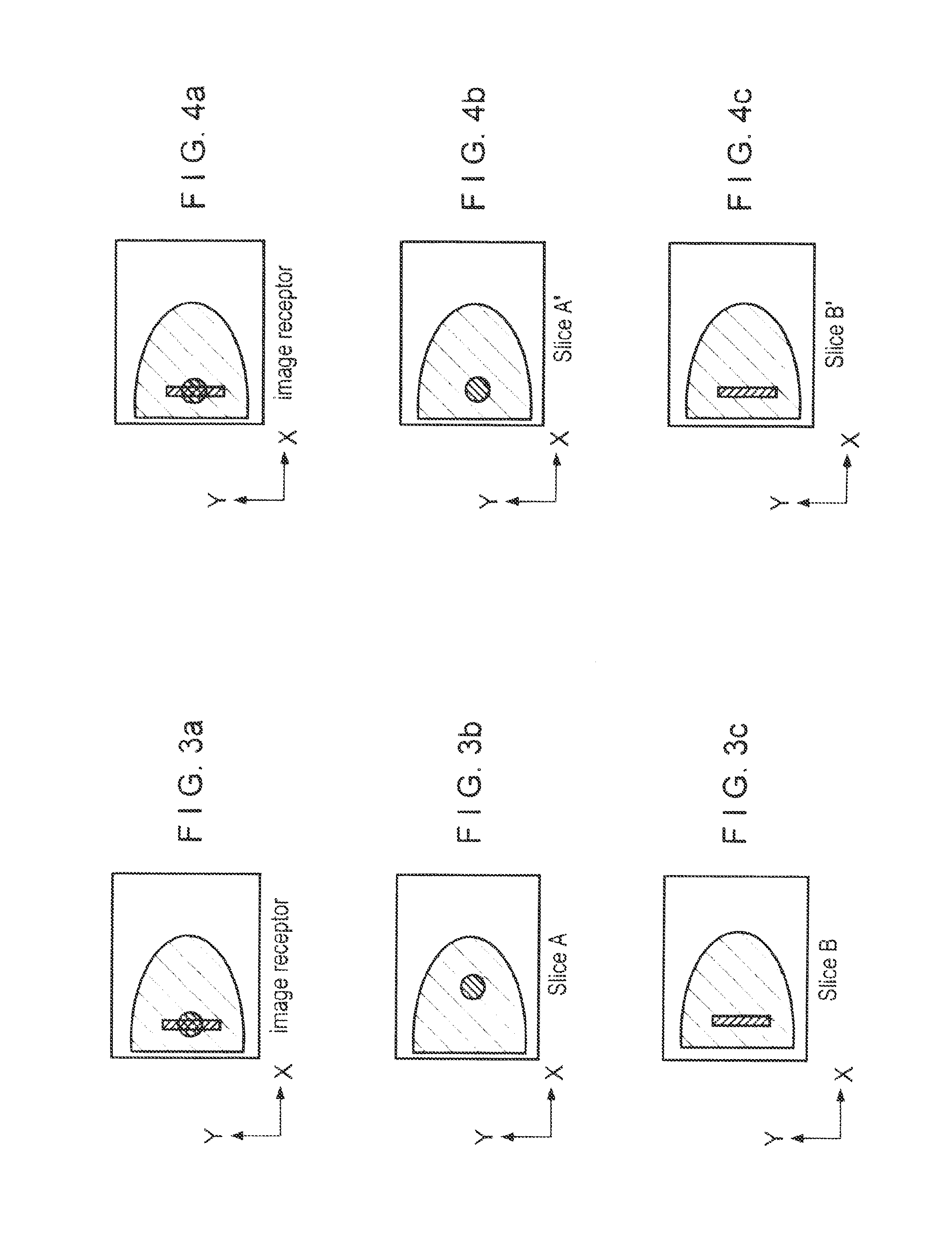
FIGS. 3a, 3b, and 3c illustrate, respectively, a conventional mammogram and two tomosynthesis slice images, where two objects that are at different heights in the breast appear superimposed in the mammogram but at different relative locations in the tomosynthesis slice images.
FIGS. 4a, 4b, and 4c illustrate, respectively, a conventional mammogram and two tomosynthesis slice images, where two objects that are at different heights in the breast appear superimposed in the mammogram but at locations in the tomosynthesis slice images that match their locations in the mammogram.
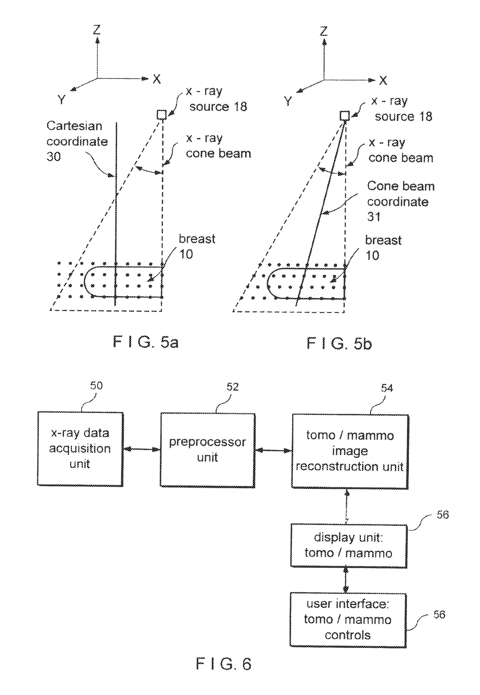
FIGS. 5a and 5b illustrate, respectively, tomosynthesis reconstruction into a Cartesian and into a cone-beam geometry.
FIG. 6 is a block diagram of a system implementing an example of an embodiment of the disclosed methods and systems.
DETAILED DESCRIPTION OF PREFERRED EMBODIMENTS
FIGS. 1a and 1b illustrate in simplified view an example of geometry for CC (cranial-caudal) imaging of a patient's breast 10. Breast 10 is compressed between an image receptor 12, such as a flat panel digital imager, and a compression paddle 14, and is imaged with a cone-shaped or pyramid-shaped x-ray beam 16 from an x-ray source 18. FIG. 1a illustrates a front view where the long axis of the compressed breast 10 is normal to the sheet, and FIG. 1b illustrates a side view where the long axis of the breast is in the plane of the sheet and where the patient's chest (not shown) is to the right of the illustrated geometry. Respective coordinate systems are shown above FIGS. 1a and 1b. In pertinent respect, the illustrated geometry is similar to that used in the Selenia.TM. mammography system identified above as well as in the tomosynthesis system disclosed in said patent application Ser. No. 10/723,486. As is known, the breast can be compressed and imaged in other orientations as well.
FIG. 2 illustrates the same geometry as FIG. 1b, and the same coordinate system, except that it highlights a single raypath or x-ray trajectory 20 rather than illustrate the entire x-ray beam 16. In addition, FIG. 2 illustrates two objects in breast 10, object #1 at slice A and object #2 at slice B. The term object is used here to refer to any structure that can be imaged in a mammogram or a tomosynthesis image, such as a lesion in the breast, and the term slice is used to refer to a layer of the breast of a finite thickness, e.g. thickness in the z-direction, that is less than the total breast thickness. For example, a slice can be a few mm thick, or thinner or thicker.
In tomosynthesis images, the same objects #1 and #2 can appear at different locations relative to other structure in the breast as compared with a mammogram of the same breast, as illustrated in FIGS. 3a-3c. FIG. 3a illustrates a mammogram that can be obtained with the geometry of FIG. 2, while FIGS. 3b and 3c illustrate tomosynthesis images of slices A and B, respectively, obtained with a system as disclosed in said application Ser. No. 10/723,486. Because objects #1 and #2 are along the same x-ray trajectory 20, they appear superimposed in the mammogram of FIG. 3a. However, because x-ray trajectory 20 is not normal to the image plane of receptor 12, as is the general case with x-ray trajectories when using such cone-beam or pyramid-beam x-ray geometry, the two objects appear at different xy locations in the tomosynthesis images of FIGS. 3b and 3c. These tomosynthesis images can be conceptualized as vertical projections of slices A and B onto the image plane of the mammogram, e.g. the image plane of x-ray receptor 12. Another way to conceptualize such a tomosynthesis image is to imagine that slice A alone, with no other breast tissue above or below it, were laid directly on x-ray receptor 12 and imaged. For similar reasons, the same object #2 shows up at different xy locations in FIGS. 3a and 3c.
The new approach described in this patent specification achieves a different result. Given the same data acquisition geometry (FIG. 2), the new approach generates images as illustrated in FIGS. 4b and 4c rather than those of FIGS. 3b and 3c.
FIG. 4a is the same as FIG. 3a--a mammogram that shows the same objects #1 and #2 superimposed. However, FIG. 4b differs significantly from FIG. 3b, and FIG. 4c differs significantly from FIG. 3c. In particular, FIGS. 4b and 4c show the images of objects #1 and #2 at xy locations that are in the same coordinate system. Moreover, in this example this is the same coordinate system as that of the mammogram of FIGS. 4a (and 3a). Both FIGS. 4b and 3b are tomosynthesis images of slice A, but FIG. 4c shows object #2 in slice image A' at the correct xy location that matches the location of the same object in the mammogram of FIG. 4a. Similarly, both FIGS. 4c and 3c are tomosynthesis images of slice B, but FIG. 4c shows object #2 in slice image B' at the correct xy location that matches the location of the same object in the mammogram of FIG. 4a.
The reason for the difference between FIGS. 3b and 4b, and between FIGS. 3c and 4c, is not in how the underlying x-ray measurements are derived but in how the tomosynthesis images are reconstructed and displayed. All relevant x-ray measurements can be obtained as disclosed in said patent application Ser. No. 10/723,486, as one example, typically as respective 2D sets of pixel values (x-ray measurements for elemental picture areas) at each of several different angles of x-ray beam 16 relative to breast 10, e.g. at several equidistant angles over a range of .+-.15.degree.. Other raw x-ray data acquisition techniques can be used in the alternative. After pre-processing of the type known in the mammography and breast tomosynthesis art, those pixel values can be reconstructed into a rectangular Cartesian coordinate system (30 in FIG. 5a) using known reconstruction algorithms such as filtered back projection, iterative reconstruction, maximum likelihood reconstruction, or others, for example as taught in said patent application Ser. No. 10/723,486. As illustrated in FIG. 5a, the voxels (elemental volume elements) that are imaged as respective pixels in the tomosynthesis slice images are aligned along lines normal to the image plane of receptor 12. The result can be conceptualized as a set of pixel values representing x-ray properties of the voxels that are in the 3D space bound by the image plane of receptor 12 at the bottom, compression paddle 14 on top, and on the sides by the boundaries of x-ray beam 16 that impinges on receptor 12, and are uniformly spaced in xy planes. However, because x-ray beam 16 is cone-shaped or pyramid-shaped, the sides of this 3D space slope at least on three sides of the beam, and the x-ray trajectories from source 18 to receptor 12 diverge in the general case. Thus, in the general case each x-ray trajectory such as trajectory 20 is non-normal to the image plane of receptor 12. As a result, the height of an object in breast 10 influences where the image of that object will be in a mammogram taken with receptor 12. Stated differently, if two objects in the breast are along the same line normal to the image plane, in general they will appear spaced from each other in the mammogram but if the same two objects are along one of the sloping x-ray trajectory, they will appear superimposed in the mammogram. When tomosynthesis reconstruction directly or indirectly calculates a pixel image of a slice that is both parallel to the mammogram image plane and is in the same coordinate system as the mammogram, as disclosed in this patent specification, the resulting tomosynthesis image in general can show the image of an object in the breast at the same position relative to other tissue in the same slice in the breast in all tomosynthesis slice images and will better match the mammogram image.
Conceptually, images such as in FIGS. 4b and 4c can be obtained by projecting each of several horizontal breast slices separately onto the image plane of the mammography image, along the actual x-ray trajectories included in x-ray beam 16. This can be conceptualized by imagining that a slice such as slice A keeps its physical position illustrated in FIG. 2, all other breast tissue is absent, and a projection image is taken of slice A alone, using the geometry of FIG. 2. Of course, this cannot be done literally because of the presence of breast tissue above and/or below the slice. In the methods and systems disclosed in this patent specification, this result can be achieved directly or indirectly, by implementing a reconstruction algorithm of the type described in the Grant article cited above, adapted to the geometry and other characteristics of a particular x-ray data acquisition system without undue experimentation by a programmer of ordinary skill in the art. For a cone beam x-ray illumination, the reconstruction geometry can be a cone beam coordinate system 31 shown in FIG. 5b, where the voxels that correspond to pixels in the tomosynthesis slice images are at different xy spacings (and differ in size at least in the xy plane) in different slices and corresponding voxels of different slices are along the same (generally sloping) x-ray trajectory. Alternatively, the desired result can be achieved indirectly, by first reconstructing tomosynthesis images that together represent a three dimensional space having at least three sloping sides matching the geometry of the imaging x-ray beam (as in the coordinate system of FIG. 5a), and then geometrically projecting the pixel values of such tomosynthesis images onto the image plane of the mammogram along the directions of respective x-ray trajectories in the x-ray beam, again using a computer-implemented process adapted without undue experimentation to a particular x-ray data acquisition geometry by a programmer of ordinary skill in the art.
Tomosynthesis slice images such as in FIGS. 4b and 4c can facilitate assessment of breast features by allowing more direct and simplified comparison between different tomosynthesis slice images and between tomosynthesis slice images on the one hand and conventional mammograms on the other hand. With images such as in FIGS. 4a-4c, the health professional can read a mammogram (FIG. 4a) in a conventional manner, but can also display and view any one or several of a number of tomosynthesis slice images of the same breast to visualize and assess structures that can be at different heights in the breast but appear at the same or at least matching relative locations in each image in which they show. The mammogram and the tomosynthesis slice images can be displayed on the same monitor or screen, displaying one image at a time by alternating from one image to another with a suitable switch or other interface controlled by the health professional. Alternatively, one or more tomosynthesis and/or mammogram images can be displayed on one monitor or screen while one or more other images can be displayed on another monitor or screen, to allow for simultaneous viewing. As another approach, two or more tomosynthesis and/or mammogram images can displayed at respective locations on the same monitor or screen. In each case, a control interface can allow the health professional to select the images for display and the locations for display of those images.
Reconstructing and displaying tomosynthesis slice images (FIGS. 4b and 4c) as described above is particularly suitable for use in conjunction with computer-aided diagnosis (CAD) of breast images. In CAD, as currently practiced through equipment and/or software provided by companies such as R2 Technology, Inc. of Sunnyvale, Calif., an x-ray breast image is computer-analyzed and image markers are generated and displayed to indicate the location of suspected abnormalities and, in some cases, the likely type of abnormality. When the tomosynthesis slice images are as in FIGS. 4b and 4c, such markers can be accurately and easily displayed at correct locations relative to the tomosynthesis slice image, even when such markers are generated based solely or mainly on the appropriate mammogram. In addition, fusion images can be generated and selectively displayed under the control of a health professional. For example, a mammogram such as in FIG. 4a and a slice image such as in FIG. 4b or 4c can be superimposed for display, for example with the mammogram in gray scale or in a first selected color or set of colors and the tomosynthesis image in a second selected color or set of colors. The fused image can further include CAD markers displayed at the appropriate locations.
Another display method is to select a region of interest in a mammogram, for example by the health professional drawing or otherwise indicating a region of interest (ROI), and replacing the ROI with the corresponding portion of a selected tomosynthesis slice image. The particular tomosynthesis slice image or succession of such images can be selected by the health professions through an appropriate interface such a track ball or mouse buttons or wheel. The health professional can scroll up and down the height of the imaged breast and see tomosynthesis images within the ROI without losing landmark orientation relative to other parts of the breast that are still seen in the portion of the mammogram outside the ROI. Still in addition, the tomosynthesis x-ray measurements and/or images described above can be used to reconstruct or reformat slice images conforming to planes that are not parallel to the image plane of a mammogram, using image processing techniques known in technologies such as CT (computerized tomography) scanning, and to reconstruct or reformat 3D displays of the imaged breast or selected portions of the breast, for display alone or in conjunction with the display of one or more mammograms and/or 3D tomosynthesis slice images.
FIG. 6 illustrates in block diagram form an example of a system implementing technology described above. An x-ray data acquisition unit 50 acquires x-ray measurements for tomosynthesis and/or mammogram images, for example as described in patent application Ser. No. 10/723,486. A pre-processing unit 52 applies known gain and offset corrections to the raw x-ray measurements from unit 50, and known normalization/log conversion of the corrected data. Image reconstruction unit 54 uses the pre-processed x-ray measurements to generate appropriate tomosynthesis and/or mammographic images. Such images are displayed at unit 56, under the control of a user interface 58 that includes controls such a keyboard, mouse, etc. to select and manipulate the displayed images as well as to control units 50-58 for other purposes.
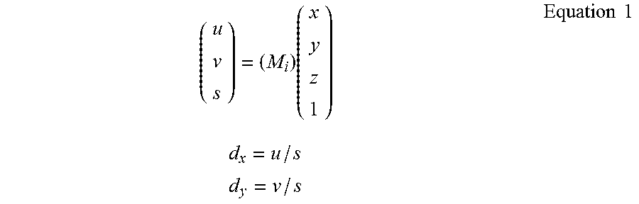
For the reconstruction processing carried out in unit 54, a geometry matrix can be defined from a geometry calibration file and input projection angles appropriate to unit 50 for use in backprojection, from fits to the matrix elements determined from a geometry calibration of unit 50 and input projection angles measured by an encoder in unit 50. Image processing and filtering can be carried out on the images prior to reconstruction, using image processing techniques known in technologies such as CT scanning and tomosynthesis. A known skin line correction can also be applied at this stage. A backprojection can then be carried out, one tomosynthesis slice at a time, using the geometry matrix as follows,
.times..times..times..times..times..times..times. ##EQU00001## where M.sub.i is the 3.times.4 geometry matrix for projection i, (x,y,z) is the location of an image pixel, and (d.sub.x,d.sub.y) is the location on the x-ray detector element or area for the line that connects a focal spot in source 18 and the image pixel. This method of backprojection is described, for example, in section 3.4 in Faugeras, O., Three-Dimensional Computer Vision, A Geometric Viewpoint, (MIT Press, 2001), hereby incorporated by reference in this specification.
In a first method, using Cartesian coordinates as in FIG. 5a, the reconstructed slices are parallel to the breast plate, or parallel to the image plane of receptor 12 at 0.degree. projection angle. Voxels and their corresponding image pixels are equally spaced in x-y (in-plane). The x-y pixel spacing is the same for each image slice. The z-pixel spacing is the desired output slice separation. In a second method, using cone beam coordinates as in FIG. 5b, the in-slice pixel spacing varies as a function of slice number, or distance from the focal spot in source 18. The image slices are confined to the volume defined by a given source/detector location, that is, the volume defined by the four lines connecting the x-ray source point to the four corners of image receptor 12 (or any four points on receptor 12). M is first transformed by another matrix to obtain reconstructed planes that are parallel to receptor 12 at some other arbitrary projection angle. This rotation matrix is obtained from the geometry matrix of that projection. In addition, a pixel size scale factor and pixel starting location (corner of a given slice) are calculated for each slice. The scale factor depends on the number of projections that intersect the given pixel. That is, some pixels are not `seen` by all projections. This scaling reduces band artifacts near the edge of the image.
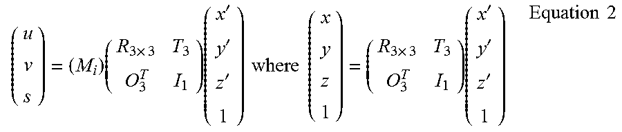
The tomosynthesis image slices to be reconstructed can be parallel to a "default" reference plane as suggested by Equation 1 above. Alternatively, they can be at other preferred orientations, defined by a 4.times.4 matrix multiplication operation applied to the original 3.times.4 matrix M, according to:
.times..times..times..times.'''.times..times..times..times..times..times.- .times.'''.times..times. ##EQU00002##
For example, a preferred orientation can be an orientation in which a particular mammogram is taken.
Thus, the backprojection for reconstructing tomosynthesis slice images can involve: 1.) The selection of the orientation of image slices to be reconstructed. The slice can be either parallel to the "default" reference plane as suggested by Equation 1, or at another more preferred orientation, which is defined by a 4.times.4 matrix multiplication operation to the original 3.times.4 matrix M, as expressed by Equation 2; and 2.) Selection of the reconstruction voxel grid in space, which can be either a Cartesian grid (FIG. 5a) or a Cone beam grid (FIG. 5b).
It should be clear to those skilled in the relevant technology that the above description is only one example of implementing the new approach and that numerous variations are possible that are within the scope of the description above.
Thus, in one non-limiting example, this patent specification discloses a method comprising: obtaining tomosynthesis x-ray measurements and at least one 2D x-ray projection mammogram of a patient's breast, wherein the mammogram image and the tomosynthesis measurements are obtained using a cone-shaped or pyramid-shaped imaging x-ray beam, and reconstructing 2D tomosynthesis images from the tomosynthesis measurements, wherein the tomosynthesis images conform to the same geometric coordinate system as the 2D projection mammogram, whereby anatomical structures that appear in the mammogram appear at geometrically corresponding places in respective ones of the tomosynthesis images. The step or steps of reconstructing 2D tomosynthesis images can comprise using a computer-implemented cone beam reconstruction algorithm directly generating the tomosynthesis images. Alternatively, the step or steps of reconstructing the 2D tomosynthesis images can comprise generating information describing initial tomosynthesis images, in which tissue or objects in the breast that are at different heights in the breast but overlap in the mammogram appear at mismatched positions in the initial tomosynthesis images, and using the information describing the initial tomosynthesis images to generate final tomosynthesis images in which said tissue or objects appear at positions that match their positions in the mammogram. This alternative can be implemented by generating the initial tomosynthesis images in an initial coordinate system different from that of the mammogram, and processing the information describing the initial tomosynthesis images into tomosynthesis images that match the coordinate system of the mammogram. In the initial coordinate system, the initial tomosynthesis images may differ in pixel spacing while the final tomosynthesis images may have the same pixel spacing. The final pixel spacing may be the same as in the mammogram.
This patent specification also discloses, as another non-limiting example, an x-ray system comprising an x-ray data acquisition unit that uses a cone-shaped or pyramid shaped x-ray beam and an x-ray receptor to obtain tomosynthesis x-ray measurements and x-ray measurements for at least one 2D x-ray projection mammogram of a patient's breast, a pre-processor that receives said measurements from the x-ray receptor and subjects them to pre-processing operations, a tomo/mammo image reconstruction unit that receives the pre-processed images and subjects them to further processing to reconstructing 2D tomosynthesis images and a mammogram, wherein tissue or objects in the breast that are at different heights in the breast but appear superimposed in the mammogram appear at locations in the tomosynthesis images that are the same as or at least match their location in the mammogram, and a display unit that selectively displays one or more of the tomosynthesis images and the mammogram and is under the control of a used interface operated by a health professional. The image reconstruction unit can use a computer-implemented cone beam reconstruction algorithm directly generating the tomosynthesis images. Alternatively, the image reconstruction unit can generate information describing initial tomosynthesis images, in which tissue or objects in the breast that are at different heights in the breast but overlap in the mammogram appear at mismatched positions in the initial tomosynthesis images, and can use the information describing the initial tomosynthesis images to generate final tomosynthesis images in which said objects appear at positions that are the same as or at least match their positions in the mammogram. This alternative can be implemented by generating the initial tomosynthesis images in an initial coordinate system different from that of the mammogram, and processing the information describing the initial tomosynthesis images into tomosynthesis images that match the coordinate system of the mammogram. In the initial coordinate system, the initial tomosynthesis images may differ in pixel spacing while the final tomosynthesis images may have the same pixel spacing. The final pixel spacing may be the same as in the mammogram.
* * * * *
References
D00000
D00001
D00002
D00003
D00004
D00005
M00001
M00002
XML
uspto.report is an independent third-party trademark research tool that is not affiliated, endorsed, or sponsored by the United States Patent and Trademark Office (USPTO) or any other governmental organization. The information provided by uspto.report is based on publicly available data at the time of writing and is intended for informational purposes only.
While we strive to provide accurate and up-to-date information, we do not guarantee the accuracy, completeness, reliability, or suitability of the information displayed on this site. The use of this site is at your own risk. Any reliance you place on such information is therefore strictly at your own risk.
All official trademark data, including owner information, should be verified by visiting the official USPTO website at www.uspto.gov. This site is not intended to replace professional legal advice and should not be used as a substitute for consulting with a legal professional who is knowledgeable about trademark law.