Compact image intensifier objective with gradient index lenses
Moore
U.S. patent number 10,247,925 [Application Number 15/610,874] was granted by the patent office on 2019-04-02 for compact image intensifier objective with gradient index lenses. This patent grant is currently assigned to THE UNITED STATES OF AMERICA, AS REPRESENTED BY THE SECRETARY OF THE ARMY. The grantee listed for this patent is The United States of America, as represented by the Secretary of the Army, The United States of America, as represented by the Secretary of the Army. Invention is credited to Sean A. Moore.


| United States Patent | 10,247,925 |
| Moore | April 2, 2019 |
Compact image intensifier objective with gradient index lenses
Abstract
An innovative design for a compact objective lens for use with a digital image intensification camera is described, which uses lenses made with gradient index materials to reduce the number of lens elements required, length and weight over conventional objective lens systems.
| Inventors: | Moore; Sean A. (Springfield, VA) | ||||||||||
|---|---|---|---|---|---|---|---|---|---|---|---|
| Applicant: |
|
||||||||||
| Assignee: | THE UNITED STATES OF AMERICA, AS
REPRESENTED BY THE SECRETARY OF THE ARMY (Washington,
DC) |
||||||||||
| Family ID: | 64460259 | ||||||||||
| Appl. No.: | 15/610,874 | ||||||||||
| Filed: | June 1, 2017 |
Prior Publication Data
| Document Identifier | Publication Date | |
|---|---|---|
| US 20180348489 A1 | Dec 6, 2018 | |
| Current U.S. Class: | 1/1 |
| Current CPC Class: | G02B 13/005 (20130101); G02B 3/0087 (20130101); G02B 13/16 (20130101); G02B 13/0055 (20130101); G02B 23/12 (20130101); G02B 13/004 (20130101) |
| Current International Class: | G02B 13/16 (20060101); G02B 3/00 (20060101); G02B 13/00 (20060101) |
| Field of Search: | ;359/652-655,715,771-783 |
References Cited [Referenced By]
U.S. Patent Documents
| 3873408 | March 1975 | Hensler |
| 3904268 | September 1975 | Keck et al. |
| 4830476 | May 1989 | Aoki |
| 4859040 | August 1989 | Kitagishi et al. |
| 4902650 | February 1990 | Caldwell et al. |
| 5184251 | February 1993 | Tsuchida |
| 5392431 | February 1995 | Pfisterer |
| 5448409 | September 1995 | Noda |
| 5621574 | April 1997 | Foo |
| 5623370 | April 1997 | Ueda |
| 6714354 | March 2004 | Trotter, Jr. |
| 7167317 | January 2007 | Jung et al. |
| 8837053 | September 2014 | Ishihara |
| 2013/0003186 | January 2013 | Beadie et al. |
| 2015/0307385 | October 2015 | Klein et al. |
Other References
|
Ohara, "Optical Glass, Technical Information." (Year: 2013). cited by examiner . Schott, "Optical Glass, Data Sheets." (Year: 2013). cited by examiner. |
Primary Examiner: Pasko; Nicholas R.
Attorney, Agent or Firm: Kim; Richard J.
Government Interests
GOVERNMENT INTEREST
The invention described herein may be manufactured, used, sold, imported, and/or licensed by or for the Government of the United States of America.
Claims
What is claimed is:
1. A compact image intensifier objective based on gradient index lenses for a digital image intensification device, comprising: a first GRIN lens having its front surface disposed nearest an object space, wherein the front surface of said first GRIN lens has a diameter of 15.74 mm and a radius of curvature of 32.48 mm; a meniscus lens with its front surface facing a back surface of said first GRIN Lens; a double convex lens with its front surface facing a back surface of said meniscus lens; and a second GRIN lens having its back surface disposed nearest an image space such that an image from said object space passing through said first GRIN lens, said meniscus lens, said double convex lens, and said second GRIN lens is focused onto an image plane of said image space.
2. The compact image intensifier objective recited in claim 1, wherein said first GRIN lens is a gradient index element with a radial profile.
3. The compact image intensifier objective recited in claim 1, wherein the back surface of said first GRIN lens has a diameter of 13.06 mm and a radius of curvature of 14.54 mm.
4. The compact image intensifier objective recited in claim 1, wherein said first GRIN lens is a gradient index element having an index of refraction that varies across the gradient index element, the index of refraction being highest at a center optical axis of said first GRIN lens.
5. The compact image intensifier objective recited in claim 1, wherein an internal aperture stop is disposed between the back surface of said first GRIN lens and the front surface of said meniscus lens.
6. The compact image intensifier objective recited in claim 1, wherein the front surface of said meniscus lens has a diameter of 12.96 mm and a radius of curvature of -81.89 mm, the back surface having a diameter of 13.46 mm and a radius of curvature of -150.22 mm.
7. The compact image intensifier objective recited in claim 1, wherein the front surface of said double convex lens has a diameter of 14.00 mm and a radius of curvature of -712.58 mm, the back surface having a diameter of 15.16 mm and a radius of curvature of -17.34 mm.
8. The compact image intensifier objective recited in claim 1, wherein said second GRIN lens is a gradient index element with a radial profile.
9. A compact image intensifier objective based on gradient index lenses for a digital image intensification device, comprising: a first GRIN lens having its front surface disposed nearest an object space; a meniscus lens with its front surface facing a back surface of said first GRIN Lens; a double convex lens with its front surface facing a back surface of said meniscus lens; and a second GRIN lens having its back surface disposed nearest an image space such that an image from said object space passing through said first GRIN lens, said meniscus lens, said double convex lens, and said second GRIN lens is focused onto an image plane of said image space, wherein the front surface of said second GRIN lens has a diameter of 15.18 mm and a radius of curvature of 11.01 mm.
10. The compact image intensifier objective recited in claim 1, wherein said first and second GRIN lenses are gradient index elements, each having a respective index of refraction that varies across the gradient index element and in relation to wavelength.
11. A compact image intensifier objective based on gradient index lenses for a digital image intensification device, comprising: a first GRIN lens having its front surface disposed nearest an object space; a meniscus lens with its front surface facing a back surface of said first GRIN Lens; a double convex lens with its front surface facing a back surface of said meniscus lens; and a second GRIN lens having its back surface disposed nearest an image space such that an image from said object space passing through said first GRIN lens, said meniscus lens, said double convex lens, and said second GRIN lens is focused onto an image plane of said image space, wherein the back surface of said second GRIN lens has a diameter of 12.14 mm and a radius of curvature of 7.87 mm.
12. The compact image intensifier objective recited in claim 1, wherein said second GRIN lens is a gradient index element having an index of refraction that varies across the gradient index element, the index of refraction being highest at a center optical axis of said second GRIN lens.
Description
FIELD OF THE INVENTION
This invention relates in general to optics, and more particularly, to objective lenses and gradient index elements.
BACKGROUND OF THE INVENTION
Night vision devices are currently an important asset for the warfighter. Their use has allowed soldiers a tactical advantage in low light level (i.e. nighttime) operations and increased their lethality and survivability on the battlefield.
Technology has allowed for many components of these systems to become smaller and lighter. The advance from analog image intensification tubes to digital focal planes has reduced the weight and length of these systems, and plastic optical materials have allowed for lighter eyepiece optics. Upcoming innovations promise to reduce eyepiece size and weight further.
The objective lens has resisted these trends. Plastics are not available as a material for use by the designers and manufacturers of these systems, as the haze and scatter of these materials precludes their use in front of systems that amplify the incoming light. The military has been looking for a method to reduce the length and weight of these lenses, and therefore on the strain that the soldier experiences with prolonged use of these systems.
A challenge in designing lenses for I2 devices with traditional optics has been the requirement for high performing lenses while maintaining a high numerical aperture, or low f-number, in order to gather enough photons from the object scene to maintain a high signal-to-noise ratio. In this case, the f-number for the objective lens is f/1.3. The difficulty in designing high performance systems with these requirements (large field of view, color correction over a larger waveband, and fast f-number) have led to objective designs with a large number of elements in order to meet performance as measured by spot size or modulation transfer function (MTF), a measure of contrast in the system.
SUMMARY OF THE INVENTION
The present disclosure has resolved these challenges and enables an optical system comprising of an objective which utilizes radial gradient index elements to correct aberrations in the lens performance with fewer optical elements. Specifically, these radial gradient index elements are made using glass that has been doped with an extra substance or a combination of glasses, producing lenses with an index of refraction that varies from a higher index in the center of the lenses, or along their optical axes, to a lower index at their edges.
An exemplary four element (two conventional and two using gradient index materials) is disclosed that is designed for corrected performance over the visible and near-infrared wavelengths that the image intensification (12) system is sensitive. Using these elements allows the designer to maintain performance and field of view using fewer elements, reducing weight and length.
While the exemplary solution may have been developed for the particular case of this system with a particular sensor size with specific field of view and f-number requirements, it should be noted that the technology utilized herein can be applied to numerous objective lens system configurations and requirements.
BRIEF DESCRIPTION OF THE DRAWINGS
Additional advantages and features will become apparent as the subject invention becomes better understood by reference to the following detailed description when considered in conjunction with the accompanying drawings wherein:
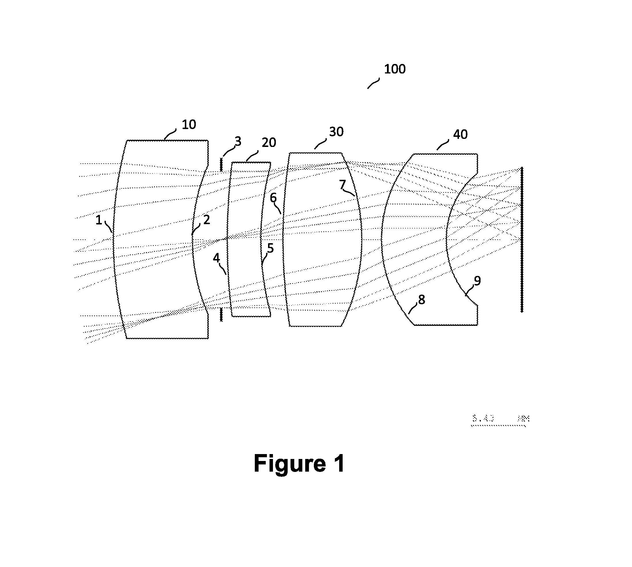
FIG. 1 shows an exemplary optical raytrace of the four element objective for a digital image intensification device.
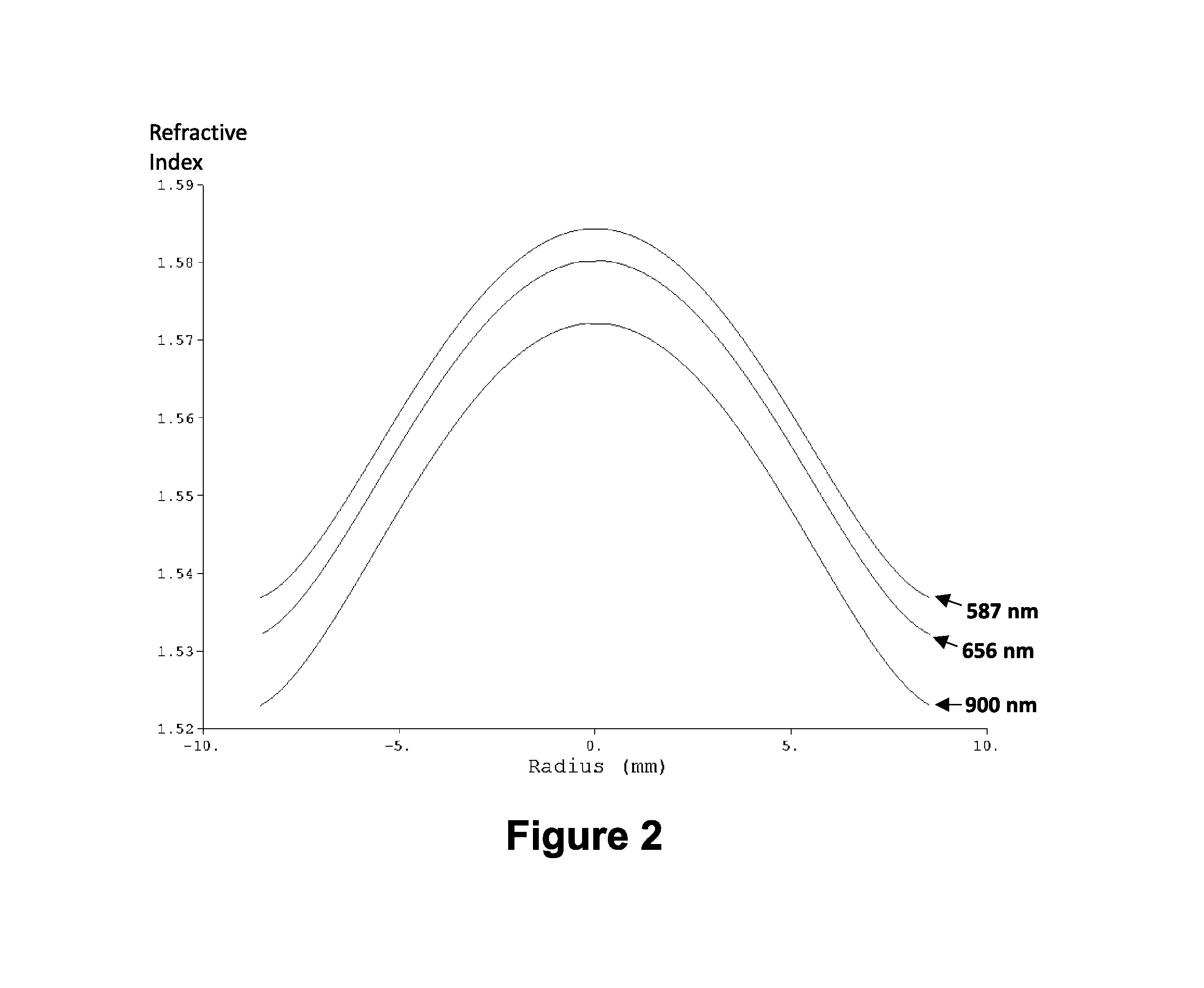
FIG. 2 shows the index profile by wavelength of the lens nearest the object space (GRIN Lens 10) at three wavelengths (587 nm, 656 nm, and 900 nm).
FIG. 3 shows the index profile by wavelength of the lens nearest the image space (GRIN Lens 40) at three wavelengths (587 nm, 656 nm, and 900 nm).
FIG. 4 shows an exemplary optical raytrace of a conventional optical objective lens that meets the same requirements as the disclosed optical design.
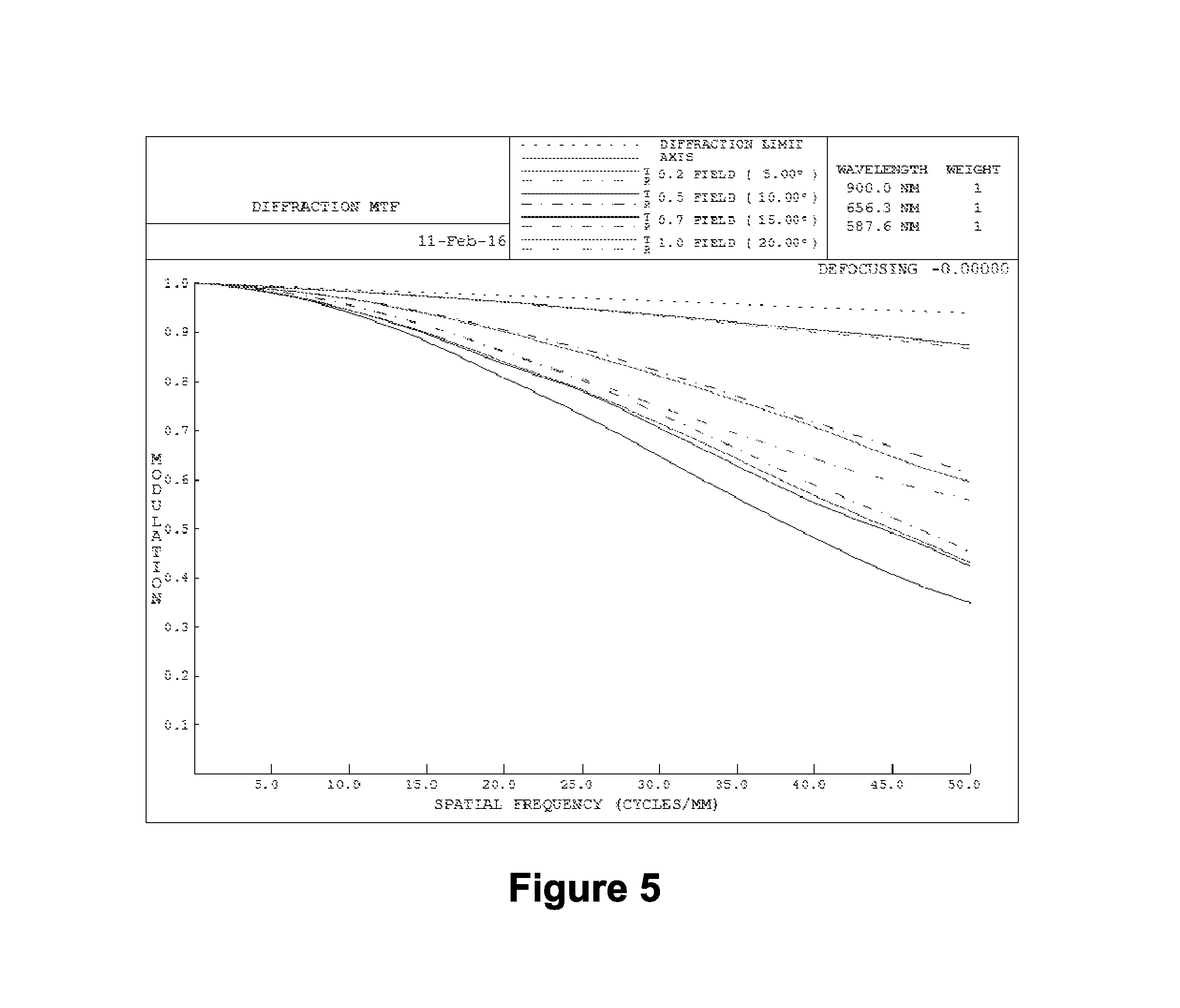
FIG. 5 shows the modulation transfer function for the exemplary optical design using two gradient index elements.
FIG. 6 shows the modulation transfer function for the equivalent exemplary conventional design.
FIG. 7 tabulates the lens data for the exemplary design with gradient index elements.
DETAILED DESCRIPTION
An optical system is disclosed comprising an objective lens with two radial gradient index lens elements.
The current disclosure includes the design of an objective lens 100 for use with a digital image intensification system. The lens design requirements compel the lens to have color corrected performance over the wavelength range that the focal plane is sensitive. The exemplary system design provided was designed to maintain corrected performance from 580 nanometers to 900 nanometers. The objective lens focal length of approximately 19 millimeters was selected to provide a 40 degree field of view in the horizontal direction over the focal plane. This parameter would be adjusted dependent on field of view requirements and the focal plane used in the system.
The approach detailed in this disclosure relies on gradient index materials. These elements have a variable index of refraction, varying along the z-axis for axial materials, y-axis for radial, and the x-y-z coordinates for spherical or more amorphous index profiles. These elements can be made using glasses doped with impurities that change the effective index to varying levels across the element, the shaping of several glass types into sheets or nested cylinders and introducing them to a high temperature diffusion process, or a 3D printing process that uses molten glass and can adjust the concentrations of two glasses during the printing process in a manner similar to US Patent Application Publication US 2015/0307385 A1 (Ser. No. 14,697,564) by Klein et al. published on Oct. 29, 2015. In this design, the glass is based on doped titanium silicate glass, which can be manufactured in a manner similar to U.S. Pat. No. 5,448,409 (Noda, 1995) or U.S. Pat. No. 4,902,650 (Caldwell, et al., 1990). (Said references are incorporated by reference.) The glass and its doping material are mixed while in powder form in concentrations according to the design's index profile and then sintered to create the solid glass lens and polished to produce the final element.
FIG. 1 shows an exemplary raytrace of the four element objective, for a digital image intensification device. The gradient index elements, otherwise referred to as gradient-index (GRIN) lenses, are the GRIN Lens 10 nearest object space and the GRIN Lens 40 nearest image space. GRIN Lens 10 is an exemplary gradient index element with a radial profile. GRIN Lens 10 is depicted in FIG. 1 as receiving rays from object space on its front aperture, or front optical surface. The front aperture 1 has a diameter of 15.74 mm and a radius of curvature (RoC) of 32.48 mm. Its back aperture 2 has a diameter of 13.06 mm and a RoC of 14.54 mm. The index of refraction for GRIN Lens 10 varies across the element and is highest in the center of the lens, at the optical axis, and becomes lower along the y-axis as the distance from the central axis to the edge of the lens increases. The index profile for GRIN Lens 10 in relation to the distance from the center of the lens for each of three wavelengths is illustrated in FIG. 2.
FIG. 2 shows the index profile by wavelength of the lens nearest the object space (GRIN Lens 10) at three wavelengths (587 nm, 656 nm, and 900 nm). The vertical axis represents the index of refraction. The horizontal axis shows the distance from the center of the lens, which is marked with the value zero on this graph. FIG. 2 illustrates the change in index of the elements in relation to wavelength, and show that if the index delta is produced by using two (or more) glasses, these glasses should be well matched in their dispersive properties.
An internal aperture stop 3 is located between the back aperture 2 of GRIN Lens 10 and the front aperture 4 of Lens 20. The aperture has a diameter of 12.90 mm.
Lens 20 is configured as an exemplary meniscus lens with its front aperture 4 facing the back aperture 2 of GRIN Lens 10. The front aperture 4 of Lens 20 can have an aperture diameter of 12.96 mm and a ROC of -81.89 mm, its back aperture 5 having an aperture diameter of 13.46 mm and ROC of -150.22 mm. Further, the material composition of Lens 20 can be based on NSK-14. Lens 30 is configured as an exemplary double convex lens with its front aperture 6 facing the back aperture 5 of Lens 20. The front aperture 6 of Lens 30 can have an aperture diameter of 14.00 mm and Radius of Curvature (ROC) of -712.58 mm, its back aperture 7 having an aperture diameter of 15.16 mm and ROC of -17.34 mm. Further, the material composition of Lens 30 can be based on SLAM-2.
GRIN Lens 40 is an exemplary gradient index element with a radial profile. GRIN Lens 40 is depicted in FIG. 1 as having its front aperture 8 facing the back aperture 7 of Lens 30. The front aperture 8 has a diameter of 15.18 mm and a RoC of 11.01 mm. Its back aperture 9 has a diameter of 12.14 mm and a RoC of 7.87 mm. The index of refraction for GRIN Lens 40 varies across the element and is highest in the center of the lens, at the optical axis, and becomes lower along the y-axis as the distance from the central axis to the edge of the lens increases. The index profile for GRIN Lens 40 in relation to the distance from the center of the lens for each of three wavelengths is illustrated in FIG. 3.
FIG. 3 shows the index profile by wavelength of the lens nearest the image space (GRIN Lens 40) at three wavelengths (587 nm, 656 nm, and 900 nm). The vertical axis represents the index of refraction. The horizontal axis shows the distance from the center of the lens, which is marked with the value zero on this graph. FIG. 3 illustrates the change in index of the elements in relation to wavelength, and show that if the index delta is produced by using two (or more) glasses, these glasses should be well matched in their dispersive properties.
FIG. 7 provides a table listing the aforementioned data for the lens elements for the exemplary objective design revealed in this disclosure. Specifically, FIG. 7 tabulates the lens data for the exemplary design with gradient index elements. Listed are characteristics including the lenses' radii of curvature, thickness, glass, semi-aperture and others used by optical design software packages.
The exemplary conventional objective design used as a comparison for this system had 7 lens elements with a length of 55 millimeters. It is illustrated in FIG. 4. The objective disclosed herein utilizing gradient index elements has 4 elements and a length of 30.9 millimeters. The weight of the lens system would also change proportionally. The gradient index elements have the capability to replace a number of conventional elements, as the change in power across the aperture resulting from the change in index can act as an aspheric surface, even though the surfaces all remain spherical. This allows the design software to find solutions that can correct for off-axis aberrations across the field of view, while also correcting the aberrations that are introduced when using larger apertures to gather more light. The modulation transfer functions for the gradient index design [FIG. 5] and the conventional design [FIG. 6] across the field of view are included for comparison.
Specifically, FIG. 5 shows the modulation transfer function for the exemplary optical design using two gradient index elements (GRIN Lens 10 and 40); whereas FIG. 6 shows the modulation transfer function for the equivalent exemplary conventional design for comparison. Both graphs include the values for object angles 0.degree., 5.degree., 10.degree., 15.degree., and 20.degree. out to a spatial frequency of 50 lp/mm.
It is obvious that many modifications and variations of the present invention are possible in light of the above teachings. It is therefore to be understood that within the scope of the appended claims, the invention may be practiced otherwise than as described.
* * * * *
D00000
D00001
D00002
D00003
D00004
D00005
D00006
D00007
XML
uspto.report is an independent third-party trademark research tool that is not affiliated, endorsed, or sponsored by the United States Patent and Trademark Office (USPTO) or any other governmental organization. The information provided by uspto.report is based on publicly available data at the time of writing and is intended for informational purposes only.
While we strive to provide accurate and up-to-date information, we do not guarantee the accuracy, completeness, reliability, or suitability of the information displayed on this site. The use of this site is at your own risk. Any reliance you place on such information is therefore strictly at your own risk.
All official trademark data, including owner information, should be verified by visiting the official USPTO website at www.uspto.gov. This site is not intended to replace professional legal advice and should not be used as a substitute for consulting with a legal professional who is knowledgeable about trademark law.