Spoke locking architecture
Lefebvre , et al.
U.S. patent number 10,247,035 [Application Number 15/206,590] was granted by the patent office on 2019-04-02 for spoke locking architecture. This patent grant is currently assigned to Pratt & Whitney Canada Corp.. The grantee listed for this patent is Pratt & Whitney Canada Corp.. Invention is credited to Guy Lefebvre, John Pietrobon.


| United States Patent | 10,247,035 |
| Lefebvre , et al. | April 2, 2019 |
Spoke locking architecture
Abstract
A spoke locking arrangement comprising a washer seated in a seat defined in a structural ring of a gas turbine engine, the washer having a portion thereof plastically deformed into an anti-rotation notch defined in the structural ring, thereby locking the washer against rotation in the seat, the washer further comprising a set of holes for receiving corresponding bolts, and wherein the washer further has at least one anti-rotation tab at each hole, the anti-rotation tabs being deformable in engagement with the bolts to individually lock the same against rotation.
| Inventors: | Lefebvre; Guy (St-Bruno-de-Montarville, CA), Pietrobon; John (Outremont, CA) | ||||||||||
|---|---|---|---|---|---|---|---|---|---|---|---|
| Applicant: |
|
||||||||||
| Assignee: | Pratt & Whitney Canada
Corp. (Longueuil, Quebec, CA) |
||||||||||
| Family ID: | 57881871 | ||||||||||
| Appl. No.: | 15/206,590 | ||||||||||
| Filed: | July 11, 2016 |
Prior Publication Data
| Document Identifier | Publication Date | |
|---|---|---|
| US 20170107857 A1 | Apr 20, 2017 | |
Related U.S. Patent Documents
| Application Number | Filing Date | Patent Number | Issue Date | ||
|---|---|---|---|---|---|
| 62196330 | Jul 24, 2015 | ||||
| Current U.S. Class: | 1/1 |
| Current CPC Class: | F16B 39/101 (20130101); F16B 39/103 (20130101); F01D 25/162 (20130101); F05D 2260/30 (20130101); F05D 2230/60 (20130101) |
| Current International Class: | F01D 25/16 (20060101); F16B 39/10 (20060101) |
References Cited [Referenced By]
U.S. Patent Documents
| 3261587 | July 1966 | Rowley |
| 3403889 | October 1968 | Ciokajlo |
| 3451456 | June 1969 | Dey |
| 3543588 | December 1970 | Richardson |
| 4050494 | September 1977 | de Claire |
| 4183207 | January 1980 | Libertini |
| 4214851 | July 1980 | Tuley et al. |
| 4321007 | March 1982 | Dennison et al. |
| 4369016 | January 1983 | Dennison |
| 4571936 | February 1986 | Nash et al. |
| 4735536 | April 1988 | Duran |
| 4747738 | May 1988 | Duran |
| 4793770 | December 1988 | Schonewald et al. |
| 4815908 | March 1989 | Duran et al. |
| 4820117 | April 1989 | Larrabee et al. |
| 4836708 | June 1989 | Chambers et al. |
| 4943013 | July 1990 | Kapala et al. |
| 4948316 | August 1990 | Duran et al. |
| 4979872 | December 1990 | Myers et al. |
| 4987736 | January 1991 | Ciokajlo et al. |
| 5076049 | December 1991 | Von Benken et al. |
| 5080555 | January 1992 | Kempinger |
| 5160251 | November 1992 | Ciokajlo |
| 5180282 | January 1993 | Lenhart et al. |
| 5236303 | August 1993 | Fowler et al. |
| 5272869 | December 1993 | Dawson et al. |
| 5292227 | March 1994 | Czachor et al. |
| 5357744 | October 1994 | Czachor |
| 5438756 | August 1995 | Halchak et al. |
| 5456719 | October 1995 | Keller |
| 5634767 | June 1997 | Dawson |
| 5746574 | May 1998 | Czachor et al. |
| 5941683 | August 1999 | Ridyard et al. |
| 6250840 | June 2001 | Urbach et al. |
| 6290442 | September 2001 | Peterkort |
| 6358001 | March 2002 | Bosel et al. |
| 6439616 | August 2002 | Karafillis et al. |
| 6439841 | August 2002 | Bosel |
| 6547518 | April 2003 | Czachor et al. |
| 6619030 | September 2003 | Seda et al. |
| 6860716 | March 2005 | Czachor et al. |
| 6883303 | April 2005 | Seda |
| 6889939 | May 2005 | Rouyre et al. |
| 7063505 | June 2006 | Czachor |
| 7195447 | March 2007 | Moniz et al. |
| 7220119 | May 2007 | Kirchmer et al. |
| 7419121 | September 2008 | Williams |
| 7584621 | September 2009 | Spitzer et al. |
| 7594404 | September 2009 | Somanath et al. |
| 7597537 | October 2009 | Bucaro et al. |
| 7610763 | November 2009 | Somanath et al. |
| 7748209 | July 2010 | Schopf et al. |
| 7775049 | August 2010 | Kumar et al. |
| 8001791 | August 2011 | Somanath et al. |
| 8061969 | November 2011 | Durocher et al. |
| 8091371 | January 2012 | Durocher et al. |
| 8099962 | January 2012 | Durocher et al. |
| 8113768 | February 2012 | Somanath et al. |
| 8181466 | May 2012 | Kumar et al. |
| 8215901 | July 2012 | Kapustka |
| 8245518 | August 2012 | Durocher et al. |
| 8347500 | January 2013 | Durocher et al. |
| 8347635 | January 2013 | Durocher et al. |
| 8371127 | February 2013 | Durocher et al. |
| 8371812 | February 2013 | Manteiga et al. |
| 8388306 | March 2013 | Somanath et al. |
| 8500392 | August 2013 | Durocher et al. |
| 8550773 | October 2013 | Almstedt et al. |
| 8578584 | November 2013 | Durocher et al. |
| 8579583 | November 2013 | Bock |
| 8616835 | December 2013 | Hashimoto |
| 8740550 | June 2014 | Tanioka |
| 8827255 | September 2014 | Woods |
| 8863531 | October 2014 | Scott et al. |
| 8876463 | November 2014 | Durocher et al. |
| 8882384 | November 2014 | Bynum |
| 8888427 | November 2014 | Ruppert et al. |
| 8920109 | December 2014 | Tham et al. |
| 8944749 | February 2015 | Durocher et al. |
| 8992173 | March 2015 | Farah et al. |
| 9011060 | April 2015 | Hyatt |
| 9097138 | August 2015 | Glahn et al. |
| 9097141 | August 2015 | Paradis |
| 9140137 | September 2015 | Mayer et al. |
| 9145908 | September 2015 | Gill et al. |
| 9151316 | October 2015 | Smith et al. |
| 9157325 | October 2015 | Suciu et al. |
| 9194252 | November 2015 | Farah et al. |
| 9200536 | December 2015 | McCaffrey |
| 9217371 | December 2015 | Farah et al. |
| 9222413 | December 2015 | Farah et al. |
| 9279341 | March 2016 | Durocher et al. |
| 9303528 | April 2016 | Sanchez et al. |
| 9316117 | April 2016 | Sanchez et al. |
| 9316153 | April 2016 | Patat et al. |
| 9328629 | May 2016 | Scott et al. |
| 9347374 | May 2016 | Suciu et al. |
| 9382844 | July 2016 | Muldoon et al. |
| 9387905 | July 2016 | Chonan |
| 9399520 | July 2016 | Cassagne et al. |
| 9410596 | August 2016 | Young et al. |
| 9447694 | September 2016 | Sanchez et al. |
| 9458721 | October 2016 | Palmer |
| 9476443 | October 2016 | Stoner |
| 9482115 | November 2016 | Harris et al. |
| 2007/0196196 | August 2007 | Schorling et al. |
| 2010/0132370 | June 2010 | Durocher |
| 2010/0132371 | June 2010 | Durocher et al. |
| 2010/0132372 | June 2010 | Durocher et al. |
| 2010/0132376 | June 2010 | Durocher |
| 2010/0275572 | November 2010 | Durocher et al. |
| 2010/0303610 | December 2010 | Wang et al. |
| 2012/0227371 | September 2012 | Johnson et al. |
| 2013/0052006 | February 2013 | Petty |
| 2013/0064647 | March 2013 | Hashimoto |
| 2013/0094951 | April 2013 | McCaffrey |
| 2013/0192238 | August 2013 | Munsell et al. |
| 2013/0192256 | August 2013 | Suciu et al. |
| 2013/0192267 | August 2013 | Sanchez et al. |
| 2013/0195624 | August 2013 | Schwarz et al. |
| 2014/0003920 | January 2014 | Scott |
| 2014/0007588 | January 2014 | Sanchez et al. |
| 2014/0013770 | January 2014 | Farah |
| 2014/0013771 | January 2014 | Farah et al. |
| 2014/0102110 | April 2014 | Farah et al. |
| 2014/0137534 | May 2014 | Sanchez et al. |
| 2014/0205447 | July 2014 | Patat et al. |
| 2014/0227078 | August 2014 | Chokshi |
| 2014/0255174 | September 2014 | Duelm et al. |
| 2015/0044032 | February 2015 | Paradis et al. |
| 2015/0064000 | March 2015 | Yagi |
| 2015/0125291 | May 2015 | Chokshi |
| 2015/0192034 | July 2015 | Bedard et al. |
| 2015/0192165 | July 2015 | Bauer et al. |
| 2015/0192167 | July 2015 | Harris et al. |
| 2015/0233295 | August 2015 | Farah et al. |
| 2015/0260057 | September 2015 | Farah et al. |
| 2015/0337681 | November 2015 | Scott et al. |
| 2015/0338005 | November 2015 | Davis et al. |
| 2015/0345337 | December 2015 | Petty et al. |
| 2015/0345338 | December 2015 | Yeager et al. |
| 2015/0354411 | December 2015 | Scott |
| 2016/0017754 | January 2016 | Kumar |
| 2016/0017807 | January 2016 | Chuong |
| 2016/0024949 | January 2016 | Wilber |
| 2016/0032775 | February 2016 | Wang et al. |
| 2016/0107276 | April 2016 | Gekht et al. |
| 2016/0146101 | May 2016 | Lee |
| 2016/0153315 | June 2016 | Kapustka et al. |
| 2016/0169050 | June 2016 | Scott et al. |
| 2016/0186614 | June 2016 | Paulino |
| 2016/0201512 | July 2016 | Bauer et al. |
| 2016/0201516 | July 2016 | Bauer et al. |
| 2016/0208644 | July 2016 | Burdick et al. |
| 2016/0208646 | July 2016 | Winn et al. |
| 2016/0208647 | July 2016 | Cherolis et al. |
| 2016/0208648 | July 2016 | Farah |
| 2016/0208655 | July 2016 | Farah et al. |
| 2016/0208699 | July 2016 | Cherolis et al. |
| 2016/0208701 | July 2016 | Cherolis et al. |
| 2016/0222827 | August 2016 | Winn et al. |
| 2016/0230598 | August 2016 | Cherolis et al. |
| 2016/0230602 | August 2016 | Broulidakis et al. |
| 2016/0230603 | August 2016 | Broulidakis et al. |
| 2016/0245105 | August 2016 | Farah et al. |
| 2016/0245114 | August 2016 | Wang |
| 2016/0265439 | September 2016 | Winn et al. |
| 2016/0273383 | September 2016 | Cherolis et al. |
| 2016/0273384 | September 2016 | Winn et al. |
| 2016/0290166 | October 2016 | Max et al. |
| 2016/0290167 | October 2016 | Porter et al. |
| 2016/0312659 | October 2016 | Lienau et al. |
| 2016/0326910 | November 2016 | Socha et al. |
| 2016/0333739 | November 2016 | Vo et al. |
| 103982465 | Aug 2014 | CN | |||
| 203778897 | Aug 2014 | CN | |||
| 105805143 | Jul 2016 | CN | |||
| 3233976 | Aug 1983 | DE | |||
| 1936210 | Jun 2008 | EP | |||
| 2192271 | Sep 2014 | EP | |||
| 2192273 | Sep 2014 | EP | |||
| 2786230 | May 2000 | FR | |||
| 898164 | Jun 1962 | GB | |||
| 913407 | Dec 1962 | GB | |||
| 1193056 | May 1970 | GB | |||
| 1361994 | Jul 1974 | GB | |||
| 1411299 | Oct 1975 | GB | |||
| 2196083 | Apr 1988 | GB | |||
| 1216286 | Dec 2012 | KR | |||
| 1558493 | Oct 2015 | KR | |||
| WO2011135199 | Nov 2011 | WO | |||
| WO2014/105572 | Jul 2014 | WO | |||
| WO2014113034 | Jul 2014 | WO | |||
| WO2014115187 | Jul 2014 | WO | |||
| WO2014137574 | Sep 2014 | WO | |||
| WO2015156882 | Oct 2015 | WO | |||
| WO2015157751 | Oct 2015 | WO | |||
Other References
|
International Search Report for PCT application No. PCT/CA2016/050817 dated Sep. 12, 2016. cited by applicant . International Search Report for PCT application No. PCT/CA2016/050818 dated Aug. 25, 2016. cited by applicant . International Search Report for PCT application No. PCT/CA2016/050825 dated Sep. 19, 2016. cited by applicant . International Search Report for PCT application No. PCT/CA2016/050824 dated Sep. 28, 2016. cited by applicant. |
Primary Examiner: Lee, Jr.; Woody A
Attorney, Agent or Firm: Norton Rose Fulbright Canada LLP
Parent Case Text
REFERENCE TO RELATED APPLICATION
The application claims priority of U.S. Provisional Application No. 62/196,330 filed on Jul. 24, 2015, the content of which is hereby incorporated by reference.
Claims
The invention claimed is:
1. A gas turbine engine comprising a plurality of structural spokes supporting a bearing housing within a structural case, each structural spoke being mounted to a first surface of the structural case, a washer seated in a seat defined in a second surface of the structural case opposite to the first surface thereof, the washer having a portion thereof plastically deformed in an anti-rotation notch defined in the structural case, the washer further having a set of holes in registry with corresponding mounting slots defined in the seat, fasteners extending through said holes and said mounting slots for threaded engagement with the structural spoke, and a set of anti-rotation tabs on said washer individually locking the fasteners against rotation.
2. The engine defined in claim 1, wherein the anti-rotation notch is defined at a periphery of the seat, and wherein the portion of the washer which is plastically deformed in the anti-rotation notch is at an outer diameter of the washer.
3. The engine defined in claim 1, wherein said anti-rotation tabs comprise a pair of anti-rotation tabs adjacent each of the holes defined in the washer, each pair of anti-rotation tabs comprising a first tab on an inner diameter of the washer and a second opposed facing tab on an outer diameter of the washer.
4. The engine defined in claim 3, wherein the anti-rotation tabs are bendable into engagement with a head of an associated one of the fasteners.
5. The engine defined in claim 1, wherein the anti-rotation tabs are bendable out of the plane of the washer for engagement with a head of the fasteners.
6. The engine defined in claim 5, wherein the seat is sized to receive the washer while the anti-rotation tabs are still lying in the plane of the washer.
7. The engine defined in claim 1, wherein the structural case is an outer structural ring of a mid-turbine frame module, and wherein the seat is defined in a radially outer circumferential surface of the outer structural ring.
8. The engine defined in claim 7, wherein the seat is recessed into the radially outer circumferential surface of the outer structural ring.
9. The engine defined in claim 1, wherein the structural spoke has a head and a shank, the shank extending along a central axis, and wherein the fasteners are threadably engaged with the head around the central axis.
10. The engine defined in claim 1, wherein the portion of the washer is punched into the anti-rotation notch.
11. In a gas turbine engine having a plurality of structural spokes structurally linking an inner structural ring to an outer structural ring; a spoke locking arrangement comprising: a washer seated in a seat defined in an outer circumferential surface of the outer structural ring, the washer having a set of holes in registry with corresponding mounting slots extending through the seat, bolts extending through said holes and said mounting slots for threaded engagement with each of the structural spokes, the bolts being individually locked against rotation by locking tabs provided on the washer, and the structural spokes being locked against rotation relative to the outer structural ring by the engagement of a portion of the washer in an anti-rotation notch defined in the outer structural ring.
12. The spoke locking arrangement defined in claim 11, wherein the portion of the washer is punched into the anti-rotation notch.
13. The spoke locking arrangement defined in claim 11, wherein the portion of the washer is plastically deformed in the anti-rotation notch.
14. The spoke locking arrangement defined in claim 11, wherein the anti-rotation notch is provided at a periphery of the seat, and wherein the portion of the washer is located at one location around an outer diameter of the anti-rotation notch.
15. The spoke locking arrangement defined in claim 11, wherein said anti-rotation tabs comprise a pair of anti-rotation tabs at each of the holes defined in the washer, each pair of anti-rotation tabs comprising a first tab projecting from an inner diameter of the washer and a second opposed facing tab projecting from an outer diameter of the washer.
16. The spoke locking arrangement defined in claim 11, wherein the anti-rotation tabs are bendable into engagement with a head of an associated one of the bolts.
17. The spoke locking arrangement defined in claim 11, wherein the anti-rotation tabs are bendable out of the plane of the washer for engagement with respective heads of the bolts.
18. A method of rotatably locking multiple bolts and a spoke, the method comprising: positioning a washer on a first side of a structural part, inserting bolts from said first side through registering holes in the washer and the structural part, threadably engaging the bolts with a structural spoke positioned on a second side of the structural part, the second side being opposite to the first side, tightening the bolts to a predetermined torque, locking the bolts against rotation by bending anti-rotation tabs formed in the washer in engagement with a head of each of the bolts, and locking the washer against rotation relative to the structural part by plastically deforming a portion of the washer in an anti-rotation notch defined in the structural part.
19. The method of claim 18, wherein plastically deforming comprises punching the washer into the locking notch.
20. The method of claim 18, wherein locking the bolts comprises trapping the head of each bolt between first and second anti-rotation tabs.
Description
TECHNICAL FIELD
The application relates generally to gas turbine engines and, more particularly, to a spoke locking architecture.
BACKGROUND OF THE ART
It is known to use structural spokes to mount a bearing casing to an outer structural ring of a gas turbine engine. For instance, such spokes may be found in mid-turbine frame modules. Each spoke typically extends radially from the outer ring through a strut in the gaspath to an inner ring supporting the bearing casing.
Conventional locking features to ensure the integrity and prevent loosening of the connection between the spokes and the inner or outer structural ring are typically composed of several individual pieces and require sufficient radial clearance for installation.
SUMMARY
In one aspect, there is provided a spoke locking arrangement comprising: a structural spoke mounted to a first surface of a structural part of a gas turbine engine, a washer seated in a seat defined in a second surface of the structural part opposite to the first surface thereof, the washer having a portion thereof plastically deformed in an anti-rotation notch defined in the structural part, the washer further having a set of holes in registry with corresponding mounting slots defined in the seat, bolts extending through said holes and said mounting slots for threaded engagement with the structural spoke, and a set of anti-rotation tabs on said washer individually locking the bolts against rotation.
According to another aspect, there is provided a gas turbine engine comprising a plurality of structural spokes supporting a bearing housing within a structural case, each structural spoke being mounted to a first surface of the structural case, a washer seated in a seat defined in a second surface of the structural case opposite to the first surface thereof, the washer having a portion thereof plastically deformed in an anti-rotation notch defined in the structural case, the washer further having a set of holes in registry with corresponding mounting slots defined in the seat, fasteners extending through said holes and said mounting slots for threaded engagement with the structural spoke, and a set of anti-rotation tabs on said washer individually locking the fasteners against rotation.
According to another aspect, there is provided a spoke locking arrangement comprising: a washer seated in a seat defined in an outer circumferential surface of the outer structural ring, the washer having a set of holes in registry with corresponding mounting slots extending through the seat, bolts extending through said holes and said mounting slots for threaded engagement with each of the structural spokes, the bolts being individually locked against rotation by locking tabs provided on the washer, and the structural spokes being locked against rotation relative to the outer structural ring by the engagement of a portion of the washer in an anti-rotation notch defined in the outer structural ring.
According to a still further aspect, there is provided a method of rotatably locking multiple bolts and a spoke, the method comprising: positioning a washer on a first side of a structural part, inserting bolts from said first side through registering holes in the washer and the structural part, threadably engaging the bolts with a structural spoke positioned on a second side of the structural part, the second side being opposite to the first side, tightening the bolts to a predetermined torque, locking the bolts against rotation by bending anti-rotation tabs formed in the washer in engagement with a head of each of the bolts, and locking the washer against rotation relative to the structural part by plastically deforming a portion of the washer in an anti-rotation notch defined in the structural part.
DESCRIPTION OF THE DRAWINGS
Reference is now made to the accompanying figures in which:
FIG. 1 is a schematic cross-section view of a gas turbine engine;
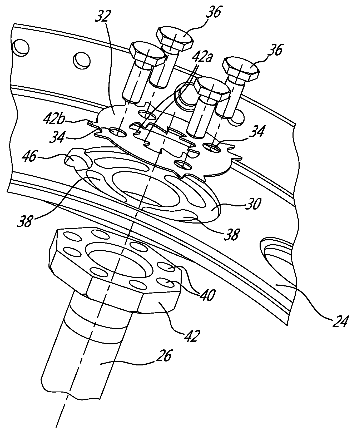
FIG. 2 is an enlarged isometric view of a portion of a mid-turbine frame module and illustrating mounting details between a spoke and an outer structural ring;
FIG. 3 is an exploded isometric view illustrating the bolted connection between the spoke and the outer structural ring;
FIG. 4 is an isometric view illustrating the anti-rotation features of the bolted connection shown in FIG. 3; and
FIG. 5 is a top isometric view illustrating how the washer of the bolted connection is deformed into an anti-rotation catch defined in the outer structural ring.
DETAILED DESCRIPTION
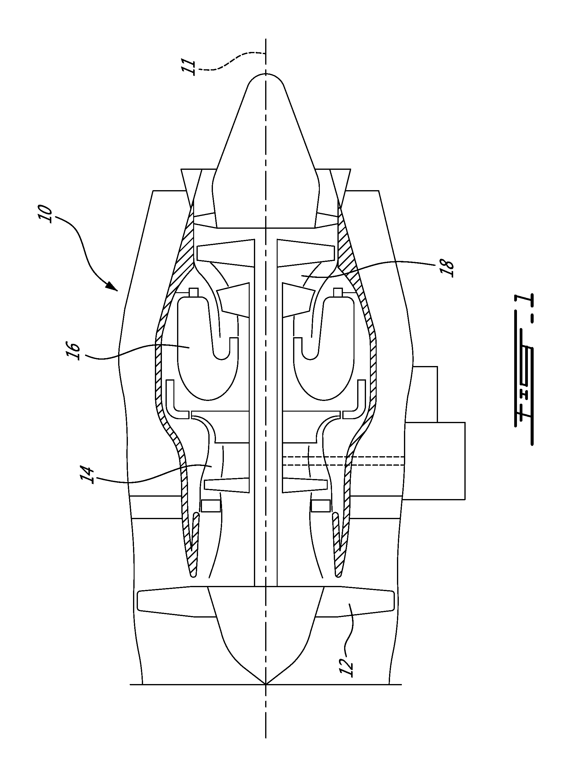
FIG. 1 illustrates a turbofan gas turbine engine 10 of a type preferably provided for use in subsonic flight, generally comprising in serial flow communication a fan 12 through which ambient air is propelled, a multistage compressor 14 for pressurizing the air, a combustor 16 in which the compressed air is mixed with fuel and ignited for generating an annular stream of hot combustion gases, and a turbine section 18 for extracting energy from the combustion gases.
FIG. 2 shows a portion of the turbine section 18. More particularly, FIG. 2 illustrates a mid-turbine frame module 20. The mid-turbine frame module 20 comprises an inner structural ring 22 adapted to receive and support a bearing casing (not shown) which is, in turn, adapted to support the main shafts of the engine 10. The inner structural ring 22 is structurally supported by an outer structural ring 24 by means of a plurality of circumferentially distributed spokes (e.g. 6), only one of which is show at 26 in FIG. 2. Each spoke 26 may extend radially through a hollow strut of a non-structural integrated strut-vane casing 28 "floatingly" mounted between the inner and outer structural rings 22 and 24 for guiding the combustion gases between two axially adjacent turbine stages.
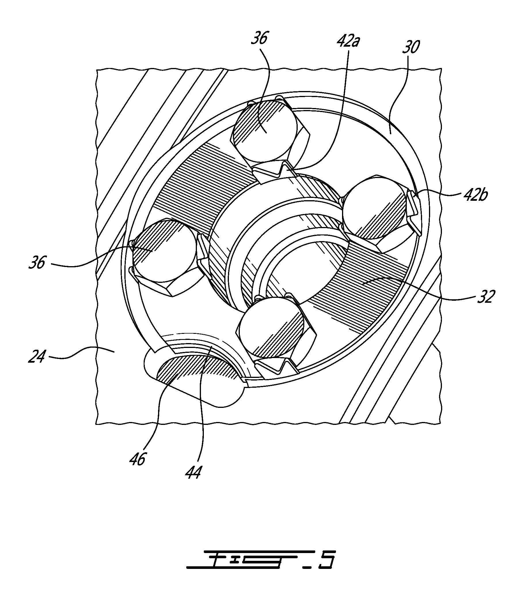
As best shown in FIGS. 3 and 4, each spoke 26 is bolted at its radially outer end to the outer structural ring 24. At each point of assembly, a seat 30 is defined in the radially outer surface of the outer ring 24 for receiving a washer 32 in a recessed fashion. The washer 32 may have a flat body with circumferentially spaced-apart holes 34 define therein for individually receiving respective bolts 36 (4 in the illustrated example). Corresponding elongated mounting slots 38 are defined in the bottom of the seat 30 for receiving the bolts 36. Each slot 38 permits alignment with at least one corresponding threaded hole 40 of an annular array of holes defined in a mounting flange or head 42 at the radially outer end of the spoke 26. Accordingly, the washer 32 is positioned in its associated seat 30 so that the holes 34 defined therein are in alignment or registry with the corresponding holes 40 of the mounting flange of the spoke 26. After the holes 34 in the washer 32 have been appropriately angularly aligned with the corresponding holes 40 in the mounting flange of the spoke 26, the bolts 36 are tighten to firmly join the spoke 26 to the outer structural ring 24.
As shown in FIGS. 3 and 4, the washer 32 is provided at each hole 34 with a pair of anti-rotation tabs 42. According to the illustrated embodiment, each pair of anti-rotation tabs 42 comprises a first tab 42a on the inner diameter of the washer 32 and an opposed facing second tab 42b on the outer diameter of the washer 32. As shown in FIG. 4, each pair of first and second tabs 42a, 42b may be bent out of the plane of the washer into engagement with the head of the associated bolt 36 to positively lock the same against rotation. In the illustrated embodiment, each pair of anti-rotation tabs 42 is engageable with opposed sides of a hexagonal head of the associated bolt 36. This effectively prevents loosening of the bolts 36. While deformable or bendable tabs have been shown, it is understood that any suitable types of locking tabs could be used as well.
Referring to FIG. 5, it can be seen that a peripheral portion 44 of the washer may be deformed into an anti-rotation notch or cavity 46 provided at one location around the perimeter of the washer seat 30. According to one embodiment, the peripheral portion 44 of the washer 32 could be punched into the anti-rotation cavity 46 after all the bolts 36 have been tighten and locked in position with the tabs 42. This prevents rotational movement of the washer 32 relative to the outer casing 24, thereby locking the spoke 26 against rotation about its longitudinal axis.
The washer 32 with its multiple locking tabs 42 provides anti-rotation to all the bolts 36 and to the spoke 26. In other words, the above described locking mechanism accomplished two functions: 1) it locks in place the structural spoke used to connect the inner ring and associated bearing casing to the outer structural ring and 2) it secures the bolts required to maintain the spoke in firm engagement with the outer structural ring. A single locking mechanism provides anti-rotation to multiple engine components having different axes of rotation (it provides anti-rotation about 5 different axes according to the illustrated embodiment).
The washer 32 with its anti-rotation tabs 42 for a plurality of bolts requires minimal clearance. It also contributes reducing the impact on engine cost and weight. It provides a simple anti-rotation mechanism with one locking feature for multiple components (5 in the illustrated embodiment--1 spoke and 4 bolts). This contributes to reduce assembly time and minimize the possibility of error.
The above description is meant to be exemplary only, and one skilled in the art will recognize that changes may be made to the embodiments described without departing from the scope of the invention disclosed. For example, a similar anti-rotation arrangement could be used to bolt the inner end of the spoke to the inner ring. Also, the anti-rotation catch or cavity could take various forms. While a pair of anti-rotation tabs has been shown and described per hole, it is understood that the number and location of tabs at each hole could vary. Also, various elements of the spoke locking architecture could be used at various locations in the engine and is thus not limited to the mounting of spokes to the outer ring of a mid-turbine frame. Indeed, the spokes could be mounted to other structural parts of the engine. Still other modifications which fall within the scope of the present invention will be apparent to those skilled in the art, in light of a review of this disclosure, and such modifications are intended to fall within the appended claims.
* * * * *
D00000
D00001
D00002
D00003
D00004
XML
uspto.report is an independent third-party trademark research tool that is not affiliated, endorsed, or sponsored by the United States Patent and Trademark Office (USPTO) or any other governmental organization. The information provided by uspto.report is based on publicly available data at the time of writing and is intended for informational purposes only.
While we strive to provide accurate and up-to-date information, we do not guarantee the accuracy, completeness, reliability, or suitability of the information displayed on this site. The use of this site is at your own risk. Any reliance you place on such information is therefore strictly at your own risk.
All official trademark data, including owner information, should be verified by visiting the official USPTO website at www.uspto.gov. This site is not intended to replace professional legal advice and should not be used as a substitute for consulting with a legal professional who is knowledgeable about trademark law.