Plastic container having a deep-set invertible base and related methods
Melrose , et al.
U.S. patent number 10,246,238 [Application Number 14/687,867] was granted by the patent office on 2019-04-02 for plastic container having a deep-set invertible base and related methods. This patent grant is currently assigned to CO2PAC LIMITED. The grantee listed for this patent is CO2PAC LIMITED. Invention is credited to John Denner, Paul Kelley, David Murray Melrose, Gregory Trude.


View All Diagrams
| United States Patent | 10,246,238 |
| Melrose , et al. | April 2, 2019 |
Plastic container having a deep-set invertible base and related methods
Abstract
A plastic container comprises an upper portion including a finish defining an opening into the container, a lower portion including a base defining a standing surface, a sidewall extending between the upper portion and the lower portion, the sidewall defining a longitudinal axis, and at least one substantially transversely-oriented pressure panel located in the lower portion. The pressure panel is movable between an outwardly-inclined position and an inwardly-inclined position to compensate for a change of pressure inside the container. The standing surface defines a standing plane, and the entire pressure panel is located between the standing plane and the upper portion of the container when the pressure panel is in the outwardly-inclined position.
| Inventors: | Melrose; David Murray (Auckland, NZ), Denner; John (York, PA), Kelley; Paul (Wrightsville, PA), Trude; Gregory (Seven Valleys, PA) | ||||||||||
|---|---|---|---|---|---|---|---|---|---|---|---|
| Applicant: |
|
||||||||||
| Assignee: | CO2PAC LIMITED (Auckland,
NZ) |
||||||||||
| Family ID: | 50232197 | ||||||||||
| Appl. No.: | 14/687,867 | ||||||||||
| Filed: | April 15, 2015 |
Prior Publication Data
| Document Identifier | Publication Date | |
|---|---|---|
| US 20160075496 A1 | Mar 17, 2016 | |
Related U.S. Patent Documents
| Application Number | Filing Date | Patent Number | Issue Date | ||
|---|---|---|---|---|---|
| 14083066 | Nov 18, 2013 | 9387971 | |||
| 11704368 | Nov 19, 2013 | 8584879 | |||
| 10529198 | Apr 10, 2012 | 8152010 | |||
| PCT/NZ03/00220 | Sep 30, 2003 | ||||
| 10851083 | Jun 9, 2009 | 7543713 | |||
| 10444616 | May 23, 2003 | ||||
| 10124734 | Sep 2, 2003 | 6612451 | |||
| 11432715 | May 18, 2010 | 7717282 | |||
| 10363400 | Jul 18, 2006 | 7077297 | |||
| PCT/NZ01/00176 | Aug 29, 2001 | ||||
| 60284795 | Apr 19, 2001 | ||||
Foreign Application Priority Data
| Aug 31, 2000 [NZ] | 506684 | |||
| Jun 15, 2001 [NZ] | 512423 | |||
| Sep 30, 2002 [NZ] | 521694 | |||
| Current U.S. Class: | 1/1 |
| Current CPC Class: | B65B 3/022 (20130101); B65D 1/0284 (20130101); B67C 3/045 (20130101); B65B 63/08 (20130101); B65B 61/24 (20130101); B65D 1/0276 (20130101); B65B 7/28 (20130101); B65D 79/005 (20130101); B29C 49/12 (20130101); B29C 49/4273 (20130101); B67C 2003/226 (20130101); B29C 49/06 (20130101); B29C 49/541 (20130101) |
| Current International Class: | B63B 3/00 (20060101); B65B 63/08 (20060101); B65B 3/02 (20060101); B65D 1/02 (20060101); B65D 79/00 (20060101); B65B 61/24 (20060101); B65B 7/28 (20060101); B67C 3/04 (20060101); B29C 49/06 (20060101); B29C 49/12 (20060101); B29C 49/54 (20060101); B29C 49/42 (20060101); B67C 3/22 (20060101) |
| Field of Search: | ;215/374 |
References Cited [Referenced By]
U.S. Patent Documents
| 1499239 | June 1924 | Malmquist |
| D110624 | July 1938 | Mekeel, Jr. |
| 2124959 | July 1938 | Vogel |
| 2378324 | June 1945 | Ray et al. |
| 2880902 | April 1959 | Owsen |
| 2960248 | November 1960 | Kuhlman |
| 2971671 | February 1961 | Shakman |
| 2982440 | May 1961 | Harrison |
| 3043461 | July 1962 | Glassco |
| 3081002 | March 1963 | Tauschinski et al. |
| 3174655 | March 1965 | Hurschman |
| 3301293 | January 1967 | Santelli |
| 3334764 | August 1967 | Fouser |
| 3397724 | August 1968 | Bolen et al. |
| 3409167 | November 1968 | Blanchard |
| 3426939 | February 1969 | Young |
| 3468443 | September 1969 | Marcus |
| 3483908 | December 1969 | Donovan |
| 3485355 | December 1969 | Stewart |
| 3693828 | September 1972 | Kneusel et al. |
| 3704140 | November 1972 | Petit et al. |
| 3727783 | April 1973 | Carmichael |
| 3819789 | June 1974 | Parker |
| 3883033 | May 1975 | Brown |
| 3904069 | September 1975 | Toukmanian |
| 3918920 | November 1975 | Barber |
| 3935955 | February 1976 | Das |
| 3941237 | March 1976 | MacGregor |
| 3942673 | March 1976 | Lyu et al. |
| 3949033 | April 1976 | Uhlig |
| 3956441 | May 1976 | Uhlig |
| 4036926 | July 1977 | Chang |
| 4037752 | July 1977 | Dulmaine et al. |
| 4079111 | March 1978 | Uhlig |
| 4117062 | September 1978 | Uhlig |
| 4120419 | October 1978 | Saunders |
| 4125632 | November 1978 | Vosti et al. |
| 4134510 | January 1979 | Chang |
| 4170622 | October 1979 | Ulhig et al. |
| 4174782 | November 1979 | Obsomer |
| 4219137 | August 1980 | Hutchens |
| 4231483 | November 1980 | Dechenne et al. |
| 4247012 | January 1981 | Alberghini |
| 4301933 | November 1981 | Yoshino et al. |
| 4318489 | March 1982 | Snyder et al. |
| 4318882 | March 1982 | Aqrawal et al. |
| 4321483 | March 1982 | Dugan |
| 4338765 | July 1982 | Ohmori et al. |
| 4355728 | October 1982 | Ota et al. |
| 4377191 | March 1983 | Yamaguchi |
| 4378328 | March 1983 | Przytulla |
| 4381061 | April 1983 | Cerny et al. |
| D269158 | May 1983 | Gaunt et al. |
| 4386701 | June 1983 | Galer |
| 4412866 | November 1983 | Schoenrock et al. |
| 4436216 | March 1984 | Chang |
| 4444308 | April 1984 | MacEwen |
| 4450878 | May 1984 | Takada et al. |
| 4465199 | August 1984 | Aoki |
| 4492313 | January 1985 | Touzani |
| 4497855 | February 1985 | Agrawal |
| 4542029 | September 1985 | Caner et al. |
| 4577775 | March 1986 | Kresin |
| 4610366 | September 1986 | Estes et al. |
| 4628669 | December 1986 | Herron et al. |
| 4642968 | February 1987 | McHenry et al. |
| 4645078 | February 1987 | Reyner |
| 4667454 | May 1987 | McHenry et al. |
| 4684025 | August 1987 | Copland et al. |
| 4685273 | August 1987 | Caner et al. |
| D292378 | October 1987 | Brandt et al. |
| 4749092 | June 1988 | Sugiura et al. |
| 4773458 | September 1988 | Touzani |
| 4785949 | November 1988 | Krishnakumar et al. |
| 4785950 | November 1988 | Miller et al. |
| 4807424 | February 1989 | Robinson et al. |
| 4813556 | March 1989 | Lawrence |
| 4831050 | May 1989 | Cassidy et al. |
| 4836398 | June 1989 | Leftault, Jr. et al. |
| 4840289 | June 1989 | Fait et al. |
| 4850493 | July 1989 | Howard, Jr. |
| 4850494 | July 1989 | Howard, Jr. |
| 4865206 | September 1989 | Behm et al. |
| 4865211 | September 1989 | Hollingsworth |
| 4867323 | September 1989 | Powers |
| 4875576 | October 1989 | Torgrimson et al. |
| 4880129 | November 1989 | McHenry et al. |
| 4887730 | December 1989 | Touzani |
| 4892205 | January 1990 | Powers et al. |
| 4896205 | January 1990 | Weber |
| 4921147 | May 1990 | Poirier |
| 4967538 | November 1990 | Leftault et al. |
| 4976538 | December 1990 | Ake |
| 4978015 | December 1990 | Walker |
| 4997692 | March 1991 | Yoshino |
| 5004109 | April 1991 | Bartley |
| 5005716 | April 1991 | Eberle |
| 5014868 | May 1991 | Wittig et al. |
| 5024340 | June 1991 | Alberghini et al. |
| 5060453 | October 1991 | Alberghini et al. |
| 5067622 | November 1991 | Garver et al. |
| 5090180 | February 1992 | Sorensen |
| 5092474 | March 1992 | Leigner |
| 5133468 | July 1992 | Brunson et al. |
| 5141121 | August 1992 | Brown et al. |
| 5178290 | January 1993 | Ota et al. |
| 5199587 | April 1993 | Ota et al. |
| 5199588 | April 1993 | Hayashi |
| 5201438 | April 1993 | Norwood et al. |
| 5217737 | June 1993 | Gygax et al. |
| 5226551 | July 1993 | Robbins, III |
| 5234126 | August 1993 | Jonas et al. |
| 5244106 | September 1993 | Takacs |
| 5251424 | October 1993 | Zenger et al. |
| 5255889 | October 1993 | Collette et al. |
| 5261544 | November 1993 | Weaver, Jr. |
| 5269428 | December 1993 | Gilbert |
| 5279433 | January 1994 | Krishnakumar et al. |
| 5281387 | January 1994 | Collette et al. |
| 5292242 | March 1994 | Robbins, III |
| 5310068 | May 1994 | Saghri |
| 5333761 | August 1994 | Davis et al. |
| 5341946 | August 1994 | Vailliencourt et al. |
| 5392937 | February 1995 | Prevot |
| 5411699 | May 1995 | Collette et al. |
| 5454481 | October 1995 | Hsu |
| 5472105 | December 1995 | Krishnakumar et al. |
| 5472181 | December 1995 | Lowell |
| RE35140 | January 1996 | Powers, Jr. |
| 5484052 | January 1996 | Pawloski et al. |
| 5503283 | April 1996 | Semersky |
| 5573129 | November 1996 | Nagata et al. |
| 5593063 | January 1997 | Claydon et al. |
| 5598941 | February 1997 | Semersky |
| 5632397 | May 1997 | Fandeux et al. |
| 5642826 | July 1997 | Melrose |
| 5672730 | September 1997 | Cottman |
| 5690244 | November 1997 | Darr |
| 5704504 | January 1998 | Bueno |
| 5713480 | February 1998 | Petre et al. |
| 5730314 | March 1998 | Wiemann et al. |
| 5730914 | March 1998 | Ruppman, Sr. |
| 5737827 | April 1998 | Kuse et al. |
| 5746339 | May 1998 | Petre et al. |
| 5758802 | June 1998 | Wallays |
| 5762221 | June 1998 | Tobias et al. |
| 5780130 | July 1998 | Hansen et al. |
| 5785197 | July 1998 | Slat |
| 5819507 | October 1998 | Kaneko |
| 5829614 | November 1998 | Collette et al. |
| 5858300 | January 1999 | Shimizu et al. |
| 5860556 | January 1999 | Robbins, III |
| 5887739 | March 1999 | Prevot et al. |
| 5888598 | March 1999 | Brewster et al. |
| 5897090 | April 1999 | Smith et al. |
| 5906286 | May 1999 | Matsuno et al. |
| 5908128 | June 1999 | Krishnakumar et al. |
| D415030 | October 1999 | Searle et al. |
| 5976653 | November 1999 | Collette et al. |
| RE36639 | April 2000 | Okhai |
| 6065624 | May 2000 | Steinke |
| 6077554 | June 2000 | Wiemann et al. |
| 6105815 | August 2000 | Mazda |
| 6176382 | January 2001 | Bazlur Rashid |
| 6213325 | April 2001 | Cheng et al. |
| 6228317 | May 2001 | Smith et al. |
| 6230912 | May 2001 | Rashid |
| 6277321 | August 2001 | Vailliencourt et al. |
| 6290094 | September 2001 | Arnold et al. |
| 6298638 | October 2001 | Bettle |
| 6375025 | April 2002 | Mooney |
| 6390316 | May 2002 | Mooney |
| 6413466 | July 2002 | Boyd et al. |
| 6439413 | August 2002 | Prevot |
| 6467639 | October 2002 | Mooney |
| 6485669 | November 2002 | Boyd et al. |
| 6502369 | January 2003 | Andison et al. |
| 6514451 | February 2003 | Boyd et al. |
| 6585124 | July 2003 | Boyd et al. |
| 6595380 | July 2003 | Silvers |
| 6612451 | September 2003 | Tobias et al. |
| 6662960 | December 2003 | Hong et al. |
| 6749780 | June 2004 | Tobias |
| 6763968 | July 2004 | Boyd et al. |
| 6769561 | August 2004 | Futral et al. |
| 6779673 | August 2004 | Melrose |
| 6923334 | August 2005 | Melrose et al. |
| 6935525 | August 2005 | Trude |
| 6942116 | September 2005 | Lisch et al. |
| 6983858 | January 2006 | Slat et al. |
| 7051889 | May 2006 | Boukobza |
| 7077279 | July 2006 | Melrose |
| 7137520 | November 2006 | Melrose |
| 7150372 | December 2006 | Lisch et al. |
| 7159374 | January 2007 | Abercrombie, III et al. |
| 7416088 | August 2008 | Boukobza |
| 7520400 | April 2009 | Young et al. |
| 7717282 | May 2010 | Melrose |
| 7726106 | June 2010 | Kelley |
| 7735304 | June 2010 | Kelley |
| 7900425 | March 2011 | Bysick et al. |
| 8047389 | November 2011 | Melrose |
| 8127955 | March 2012 | Denner et al. |
| 8152010 | April 2012 | Melrose |
| 8584879 | November 2013 | Melrose |
| 8627944 | January 2014 | Kelley |
| 8720163 | May 2014 | Melrose |
| 8726616 | May 2014 | Bysick et al. |
| 9211968 | December 2015 | Melrose |
| 9387971 | July 2016 | Melrose |
| 2001/0035391 | January 2001 | Young et al. |
| 2002/0000421 | January 2002 | Ota et al. |
| 2002/0074336 | June 2002 | Silvers |
| 2002/0096486 | July 2002 | Bourgue et al. |
| 2002/0153343 | October 2002 | Tobias et al. |
| 2002/0158038 | October 2002 | Heisel et al. |
| 2003/0015491 | January 2003 | Melrose |
| 2003/0121881 | July 2003 | Higuchi |
| 2003/0173327 | September 2003 | Melrose |
| 2003/0186006 | October 2003 | Schmidt et al. |
| 2003/0196926 | October 2003 | Tobias et al. |
| 2003/0217947 | November 2003 | Ishikawa et al. |
| 2004/0016716 | January 2004 | Melrose |
| 2004/0074864 | April 2004 | Melrose |
| 2004/0149677 | August 2004 | Slat et al. |
| 2004/0173565 | September 2004 | Semersky et al. |
| 2004/0173656 | September 2004 | Seong |
| 2004/0211746 | October 2004 | Trude |
| 2004/0232103 | November 2004 | Lisch et al. |
| 2006/0138074 | June 2006 | Melrose |
| 2006/0231985 | October 2006 | Kelley |
| 2006/0243698 | November 2006 | Melrose |
| 2006/0255005 | November 2006 | Melrose et al. |
| 2006/0261031 | November 2006 | Melrose |
| 2006/0006133 | December 2006 | Lisch et al. |
| 2007/0017892 | January 2007 | Melrose |
| 2007/0045312 | March 2007 | Abercrombie, III et al. |
| 2007/0051073 | March 2007 | Kelley et al. |
| 2007/0084821 | April 2007 | Bysick et al. |
| 2007/0125743 | June 2007 | Pritchett et al. |
| 2007/0181403 | August 2007 | Sheets et al. |
| 2007/0199915 | August 2007 | Denner et al. |
| 2007/0199916 | August 2007 | Denner et al. |
| 2007/0215571 | September 2007 | Trude |
| 2007/0235905 | October 2007 | Trude et al. |
| 2008/0047964 | February 2008 | Denner et al. |
| 2008/0298938 | December 2008 | Melrose |
| 2013/0043208 | February 2013 | Denner et al. |
| 2014/0026522 | January 2014 | Melrose |
| 2014/0165504 | June 2014 | Melrose |
| 2077717 | Mar 1993 | CA | |||
| 1586488 | Jan 1972 | DE | |||
| 1761753 | Jan 1972 | DE | |||
| 2102319 | Aug 1972 | DE | |||
| 32 15 866 | Nov 1983 | DE | |||
| 0 521642 | Jan 1993 | EP | |||
| 0551788 | Jul 1993 | EP | |||
| 0 666 222 | Sep 1995 | EP | |||
| 0609348 | Jan 1997 | EP | |||
| 0916406 | May 1999 | EP | |||
| 0957030 | Nov 1999 | EP | |||
| 1063076 | Dec 2000 | EP | |||
| 1571499 | Jun 1969 | FR | |||
| 2607109 | May 1988 | FR | |||
| 781103 | Aug 1957 | GB | |||
| 1113988 | May 1968 | GB | |||
| 2050919 | Jan 1981 | GB | |||
| 2372977 | Sep 2002 | GB | |||
| 48-31050 | Sep 1973 | JP | |||
| 49-28628 | Jul 1974 | JP | |||
| 54-72181 | Jun 1979 | JP | |||
| 56-072730 | Jun 1981 | JP | |||
| 55-114717 | Feb 1982 | JP | |||
| 63-189224 | Aug 1988 | JP | |||
| 64-009146 | Jan 1989 | JP | |||
| 03-043342 | Feb 1991 | JP | |||
| 03-076625 | Apr 1991 | JP | |||
| 04339751 | Nov 1992 | JP | |||
| 05-193694 | Aug 1993 | JP | |||
| 06-336238 | Dec 1994 | JP | |||
| 07-300121 | Nov 1995 | JP | |||
| 8053115 | Feb 1996 | JP | |||
| 8253220 | Oct 1996 | JP | |||
| 09-039934 | Feb 1997 | JP | |||
| 9110045 | Apr 1997 | JP | |||
| 10-167226 | Jun 1998 | JP | |||
| 10-181734 | Jul 1998 | JP | |||
| 10-230919 | Sep 1998 | JP | |||
| 2000-168756 | Jun 2000 | JP | |||
| 2000229615 | Aug 2000 | JP | |||
| 2002-127237 | May 2002 | JP | |||
| 2006-501109 | Jan 2006 | JP | |||
| 240448 | Oct 1995 | NZ | |||
| 296014 | Oct 1998 | NZ | |||
| 335565 | Oct 1999 | NZ | |||
| 506684 | Aug 2000 | NZ | |||
| 512423 | Jun 2001 | NZ | |||
| 521694 | Oct 2003 | NZ | |||
| 2096288 | Nov 1997 | RU | |||
| WO93/09031 | May 1993 | WO | |||
| WO1993/012975 | Jul 1993 | WO | |||
| WO9405555 | Mar 1994 | WO | |||
| WO9703885 | Feb 1997 | WO | |||
| WO97/014617 | Apr 1997 | WO | |||
| WO1997/034808 | Sep 1997 | WO | |||
| WO1999/021770 | May 1999 | WO | |||
| WO2001040081 | Dec 1999 | WO | |||
| WO2000/051895 | Sep 2000 | WO | |||
| WO2002/002418 | Jan 2002 | WO | |||
| WO2002/018213 | Mar 2002 | WO | |||
| WO2002/085755 | Oct 2002 | WO | |||
| WO2004/0028910 | Apr 2004 | WO | |||
| WO2004/106175 | Dec 2004 | WO | |||
| WO2004/106176 | Dec 2004 | WO | |||
| WO2005/012091 | Feb 2005 | WO | |||
| WO2006/113428 | Oct 2006 | WO | |||
| WO2007/127337 | Nov 2007 | WO | |||
Other References
|
ISR for PCT/US 2004/024581 dated Jul. 25, 2005. cited by applicant . ISR for PCT/NZ03/00220, mailed Nov. 27, 2003. cited by applicant . ISR for PCT/NZ01/000176 (WO 02/018213) mailed Nov. 8, 2001. cited by applicant . IPRP with Written Opinion for PCT/US2007/010182, dated Oct. 28, 2008. cited by applicant . IPRP for PCT/NZ03/00220, completed Jan. 11, 2005. cited by applicant . IPRP (including Written Opinion) for PCT/US/2004/024581 dated Jan. 30, 2006. cited by applicant . European Search Report (suppl.) of EP 03748817, dated Jul. 9, 2007. cited by applicant . Notice of Rejection of Japanese Patent Application No. 2002-523347, dated May 29, 2012. cited by applicant . Notice of Rejection in Japanese Patent Application No. 2002-523347, dated May 24, 2011. cited by applicant. |
Primary Examiner: Weaver; Sue A
Attorney, Agent or Firm: Hendricks Slavin LLP
Parent Case Text
CROSS-REFERENCE TO RELATED APPLICATIONS
The present application is a continuation of U.S. patent application Ser. No. 14/083,066(the '066 application), filed Nov. 18, 2013, now U.S. Pat. No. 9,387,971, issued Jul. 12, 2016. The '066 application is a continuation of U.S. patent application Ser. No. 11/704,368 (the '368 ), filed on Feb. 9, 2007, now U.S. Pat. No. 8,584,879, issued Nov. 19, 2013. The '368 application is a continuation-in-part of U.S. patent application Ser. No. 10/529,198, filed on Dec. 15, 2005, now U.S. Pat. No. 8,152,010 issued Apr. 10, 2012, which is the U.S. National Phase of International Application No. PCT/NZ2003/000220, filed on Sep. 30, 2003, which claims priority of New Zealand Application No. 521694, filed on Sep. 30, 2002. The '368 application is also a continuation-in-part of U.S. patent application Ser. No. 10/851,083, filed on May 24, 2004, now U.S. Pat. No. 7,543,713, issued Jun. 9, 2009, which is a continuation-in-part of U.S. application Ser. No. 10/444,616, filed on May 23, 2003, abandoned, which is a continuation-in-part of U.S. application Ser. No. 10/124,734, filed on Apr. 17, 2002, now U.S. Pat. No. 6,612,451, issued Sep. 2, 2003, which claims priority of U.S. Provisional Patent Application No. 60/284,795, filed on Apr. 19, 2001, expired. The '368 application is also a continuation-in-part of U.S. patent application Ser. No. 11/432,715, filed on May 12, 2006, now U.S. Pat. No. 7,717,282, issued May 18, 2010, which is a continuation of U.S. patent application Ser. No. 10/363,400, filed on Feb. 26, 2003, now U.S. Pat. No. 7,077,279, issued Jul. 18, 2006, which is the U.S National Phase of PCT/NZ01/00176, filed on Aug. 29, 2001, which in turn claims priority to New Zealand Patent Application No. 506684, filed on Aug. 31, 2000, and New Zealand Patent Application No. 512423, filed on Jun. 15, 2001. The disclosure of each of the aforementioned applications is incorporated herein by reference thereto.
Claims
What is claimed is:
1. A method of processing a plastic container, the method comprising the steps: inserting a preform into a mold; injecting a medium under pressure into the preform to at least partially inflate the preform such that the preform inflates substantially to complete conformity with the mold; and during inflation of the preform, moving a movable mold bottom from a retracted position to a deployed position to push a bottom of the container as the movable mold bottom moves and shapes the bottom of the container; wherein the injecting step is continued while the mold bottom is moved upwardly; wherein the mold forms a container comprising: an upper portion including a finish defining an opening into the container; a lower portion including a base defining a standing surface; a sidewall extending between the upper portion and the lower portion, the sidewall defining a longitudinal axis; and the mold bottom forms at least one substantially transversely-oriented pressure panel located in the lower portion and forming part of the base, the base including a centrally located projection and including a hollow recessed portion between the pressure panel and the standing surface, the pressure panel being movable between an outwardly-inclined position and an inwardly-inclined position to compensate for a change of pressure induced inside the container; wherein the recessed portion comprises an inner wall extending in an upward direction from the standing surface to the pressure panel; wherein the pressure panel extends in a downward direction to the centrally located projection; and wherein the standing surface defines a standing plane orthogonal to the longitudinal axis, wherein the pressure panel includes a portion that is outwardly inclined greater than about 10 degrees with respect to the standing plane when in the outwardly-inclined position, and wherein the inner wall has a length extending upwardly from the standing surface to locate the entire pressure panel between the standing plane and the upper portion of the container when the pressure panel is in the outwardly-inclined position.
2. The method of claim 1, further comprising, after said moving of the movable mold bottom from the retracted position to the deployed position, the following steps: (a) providing the plastic container for filling; (b) introducing heated liquid contents into the plastic container with the portion of the pressure panel located in the outwardly-inclined position entirely between the standing surface and the upper portion; (c) capping the plastic container; and (d) moving the pressure panel to the inwardly-inclined position entirely between the standing surface and the upper portion.
3. The method of claim 2, further comprising the step of moving the pressure panel from the inwardly-inclined position to the outwardly-inclined position prior to the step (b).
4. The method of claim 2, further comprising a step of applying mechanical force to the pressure panel to move the pressure panel from the outwardly-inclined position to the inwardly-inclined position.
5. The method of claim 2, further comprising a step of cooling the plastic container and liquid contents prior to the step (d).
6. The method of claim 2, wherein the step (d) occurs as a result of internal vacuum formed within the plastic container due to shrinkage of the liquid contents.
7. The method of claim 1, wherein the centrally located projection is recessed inwardly into the container and the surfaces of the container are blow molded with an overall thickness of at least about 10 mils. to withstand the temperature of the heated liquid.
8. The method of claim 7, wherein the inner wall has a length that exceeds a longitudinal height of the pressure panel.
9. The method of claim 1, wherein the pressure panel comprises a plurality of flutes, ribs or creases.
10. The method of claim 1, wherein the pressure panel is adapted to compensate for internal vacuum created within the container after the container is hot-filled, capped, and cooled.
11. The method of claim 1, wherein the inner wall comprises a first concave ring.
12. The method of claim 11, wherein the inner wall includes a second concave ring that is inwardly stepped further recessed into the container from the inner wall.
13. A method of processing a plastic container by blow molding, wherein the container comprises: an upper portion including a finish defining an opening into the container; a lower portion including a base defining a standing surface; a sidewall extending between the upper portion and the lower portion, the sidewall defining a longitudinal axis; and at least one substantially transversely-oriented pressure panel located in the lower portion and forming part of the base, the base including a centrally located inward projection and including a recessed portion between the pressure panel and the standing surface, the pressure panel being movable between an outwardly-inclined position and an inwardly-inclined position to compensate for a change of pressure induced inside the container; wherein the recessed portion comprises an inner wall extending in an upward direction from the standing surface to the pressure panel; wherein the pressure panel extends in a downward direction to the centrally located inward projection; and wherein the standing surface defines a standing plane orthogonal to the longitudinal axis, wherein the pressure panel includes a portion that is outwardly inclined greater than about 10 degrees with respect to the standing plane when in the outwardly-inclined position, and wherein the inner wall has a length extending upwardly from the standing surface to locate the entire pressure panel between the standing plane and the upper portion of the container when the pressure panel is in the outwardly-inclined position; and wherein the container is suitable for processing in a hot fill production line, the method comprising: (a) enclosing a softened polymer material within a blow mold defining a mold cavity, the blow mold comprising at least first and second side mold portions and a base mold portion; (b) inflating the polymer material within the blow mold to at least partially conform the polymer material to the blow mold cavity in a pre-blow step; (c) providing the base mold portion in a downward position with respect to the first and second side mold portions during inflation of the polymer material to provide for forming of the transverse pressure panel below the standing surface of the container to initially form the base to include an outward or downward step below the standing surface during the blow molding of the container; and (d) displacing the base mold portion upwardly with respect to the first and second side mold portions during inflation of the polymer material to form the transverse pressure panel deeply set within the base portion and above the standing surface of the plastic container wherein the outward or downward step is reversed into the container to provide an instep having a length extending between the standing surface and the upper portion of the container and a recess inside the standing surface.
14. The method of claim 13, further comprising a step of opening the blow mold to release the plastic container.
15. The method of claim 13, wherein the step (a) comprises enclosing a container preform as the softened polymer material within the blow mold.
16. The method of claim 15, further comprising a step of stretching the container preform with a stretch rod.
17. The method of claim 14, wherein the plastic container has a wall thickness between 10 and 15.7 thousandths of an inch.
18. The method of claim 13, wherein the mold cavity defines a longitudinal axis, and the step (d) comprises displacing the base mold portion substantially along the longitudinal axis of the mold cavity while fluid is continuously injected into a stretch rod during the blow molding process.
19. The method of claim 13, further comprising the step of substantially completely conforming the polymer material to the mold cavity prior to the step (d).
20. The method of claim 13, wherein the step (d) occurs while the polymer material is still in a softened state.
Description
BACKGROUND OF THE INVENTION
Field of the Invention
The present invention relates generally to a hot-fill container structure that allows for the removal of vacuum pressure within the container, and more particularly, to a hot-fill container structure having an invertible vacuum panel deeply set into the base of the container. The present invention also relates to methods of making and processing containers having an invertible vacuum panel deeply set into the base of the container.
Related Art
So called "hot-fill" containers are known in the art. Plastic containers, such as PET containers, are filled with various liquid contents at an elevated temperature, typically around 185.degree. F. Once the liquid within the container cools, the volume of the contained liquid reduces, creating a vacuum within the container that pulls inwardly on the side and end walls of the container. This in turn leads to deformation of the plastic container if it is not constructed rigidly enough to resist the vacuum forces.
Typically, vacuum pressures have been accommodated by the use of vacuum panels that deflect inwardly under vacuum pressure. Known vacuum panels are typically located in the container sidewall and extend parallel to the longitudinal axis of the container, and flex inwardly under vacuum pressure toward the longitudinal axis.
It is also known in the prior art to have a flexible base region to provide additional vacuum compensation. All such known prior art containers, however, have substantially flat or inwardly recessed base surfaces that deflect further inward to compensate for the vacuum forces. Known flexible base regions have not been able to adequately compensate for the vacuum forces on their own (i.e., vacuum panels in the sidewall and/or or other reinforcing structures are still required).
Therefore, there remains a need in the art for plastic containers that overcome the aforementioned shortcomings of the prior art.
BRIEF SUMMARY OF THE INVENTION
The present invention relates to a plastic container having an invertible pressure panel located in the container base. The pressure panel is movable from an initial, outwardly-inclined position, to an inverted, inwardly-inclined position, in order to reduce the volume of the container and accommodate for vacuum forces within the container. The entire pressure panel is set deeply into the base of the container, such that no portion of the pressure panel extends beyond the standing ring, regardless of whether the pressure panel is in the initial position or the inverted position. This configuration can allow the container to be supported by the standing ring regardless of whether the pressure panel is in the initial position or the inverted position.
Other plastic containers suitable for containing a liquid are disclosed in U.S. Pat. No. 5,261,544 issued to Weaver, Jr.; and U.S. Pat. No. 5,908,128 issued to Krishnakumar et al.
As disclosed in Weaver, Col. 5, lines 26-29, a polymeric container should be blow-molded with a minimum wall thickness of at least about 10 mils.
As disclosed in Krishnakumar, Col. 4, lines 17-24, a container of approximately 20 ounces in volume made from `bottle grade` PET (having about 1.5% comonomer and an intrinsic viscosity of about 0.80) may have a side-wall thickness on the order of 0.4 mm, or 15.7 mils, in order to withstand containing a heated liquid.
According to one exemplary embodiment, the present invention relates to a plastic container comprising an upper portion including a finish defining an opening into the container, a lower portion including a base defining a standing surface, a sidewall extending between the upper portion and the lower portion, the sidewall defining a longitudinal axis, and at least one substantially transversely-oriented pressure panel located in the lower portion. The pressure panel can be movable between an outwardly-inclined position and an inwardly-inclined position to compensate for a change of pressure inside the container. The standing surface can define a standing plane, and the entire pressure panel can be located between the standing plane and the upper portion of the container when the pressure panel is in the outwardly-inclined position.
According to another exemplary embodiment, the present invention relates to a method of processing a plastic container, comprising the steps of (a) providing a plastic container having an upper portion including a finish, a sidewall, a lower portion including a base defining a standing surface, and a substantially transversely-oriented pressure panel located in the base; (b) introducing heated liquid contents into the plastic container with the pressure panel located in an outwardly-inclined position entirely between the standing surface and the upper portion; (c) capping the plastic container; and (d) moving the pressure panel to an inwardly-inclined position entirely between the standing surface and the upper portion.
According to yet another exemplary embodiment, the present invention relates to a method of blow molding a plastic container, comprising the steps of (a) enclosing a softened polymer material within a blow mold defining a mold cavity, the blow mold comprising at least first and second side mold portions and a base mold portion; (b) inflating the polymer material within the blow mold to at least partially conform the polymer material to the blow mold cavity; and (c) displacing the base mold portion with respect to the first and second side mold portions to form a transverse pressure panel deeply set within a base portion of the plastic container.
Further objectives and advantages, as well as the structure and function of preferred embodiments will become apparent from a consideration of the description, drawings, and examples.
BRIEF DESCRIPTION OF THE DRAWINGS
The foregoing and other features and advantages of the invention will be apparent from the following, more particular description of a preferred embodiment of the invention, as illustrated in the accompanying drawings wherein like reference numbers generally indicate identical, functionally similar, and/or structurally similar elements.
FIG. 1 is a perspective view of an exemplary embodiment of a plastic container according to the present invention, shown with a pressure panel in an initial, outwardly-inclined position;
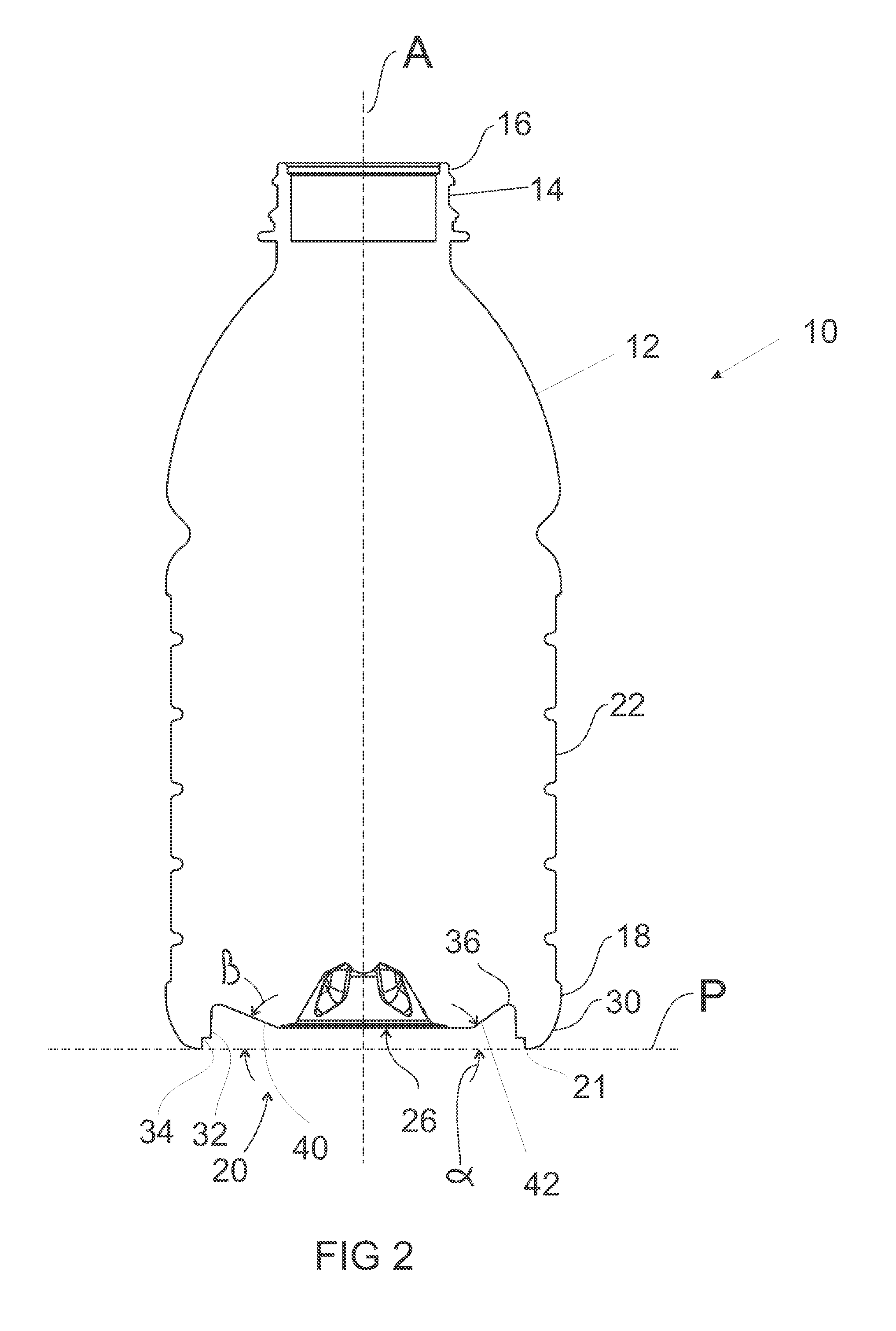
FIG. 2 is a side, sectional view of the plastic container of FIG. 1, shown with the pressure panel in the initial, outwardly-inclined position;
FIG. 3 is a side, sectional view of the plastic container of FIG. 1, shown with the pressure panel in an inverted, inwardly-inclined position;
FIG. 4 is a bottom view of the plastic container of FIG. 1;
FIG. 5 is a perspective view of another exemplary embodiment of a plastic container according to the present invention, shown with the pressure panel in the initial, outwardly-inclined position;
FIG. 6 is a bottom view of the plastic container of FIG. 5;
FIG. 7 is a perspective view of a portion of a plastic container according to yet another exemplary embodiment of the present invention, shown with the pressure panel in an initial, outwardly-inclined position;
FIG. 8 is a bottom view of the plastic container of FIG. 7;
FIG. 9 is a side, sectional view of a portion of the plastic container of FIG. 7, shown with the pressure panel in the initial, outwardly-inclined position;
FIG. 10 is a side, sectional view of a portion of the plastic container of FIG. 7, shown with the pressure panel in the inverted, inwardly-inclined position;
FIGS. 11A-E schematically illustrate an exemplary method of processing a plastic container according to the present invention;
FIGS. 12A-C schematically illustrate an exemplary method of forming a plastic container according to the present invention;
FIG. 13 illustrates a lower portion of a container similar to that shown in FIG. 7 according to an alternate embodiment;
FIG. 14 illustrates a lower portion of the container of FIG. 13 similar to the view shown in FIG. 8 according to an alternate embodiment;
FIG. 15 is a bottom plan view of FIG. 8 with planes C-C and D-D indicated;
FIG. 16 is a side section view of FIG. 15 taken along C-C; and
FIG. 17 is a side section view of FIG. 15 taken along D-D.
DETAILED DESCRIPTION OF THE INVENTION
Embodiments of the invention are discussed in detail below. In describing embodiments, specific terminology is employed for the sake of clarity. However, the invention is not intended to be limited to the specific terminology so selected. While specific exemplary embodiments are discussed, it should be understood that this is done for illustration purposes only. A person skilled in the relevant art will recognize that other components and configurations can be used without departing from the spirit and scope of the invention. All references cited herein are incorporated by reference as if each had been individually incorporated.
As discussed above, to accommodate vacuum forces during cooling of the liquid contents within a hot-fill container, plastic containers have typically included a series of vacuum panels located around the sidewall and/or in the base portion. The vacuum panels deform inwardly, and the base deforms upwardly, under the influence of the vacuum forces. This configuration attempts to prevent unwanted distortion elsewhere in the container. However, the container is still subjected to internal vacuum forces. The sidewalls and base merely provide a suitably resistant structure against that force. Additionally, the vacuum panels in the sidewall can undesirably detract from the appearance and feel of the container, and limit the design possibilities for the container.
Typically at a bottling plant, the containers are filled with a hot liquid and then capped before being subjected to a cold water spray, resulting in the formation of a vacuum within the container. The container structure needs to be able to cope with this vacuum force. U.S. patent application Ser. No. 10/529,198, filed on Dec. 15, 2005, the entire content of which is incorporated herein by reference, discloses hot-fill containers that provide for the substantial removal or substantial negation of the vacuum pressure within the containers. The disclosed containers include a transversely-oriented pressure panel located in the container base. The pressure panel is movable between an initial, outwardly inclined position, and an inverted, inwardly inclined position, in order to reduce the volume of the container and accommodate for vacuum forces within the container. The present invention relates to additional embodiments of this concept in which the pressure panel is set deeply into the base of the container, such that no portion of the pressure panel extends beyond the standing ring, regardless of whether the pressure panel is in the initial position or in the inverted position. This configuration can allow the container to be supported by the standing ring regardless of whether the pressure panel is in the initial position or the inverted position.
Referring to FIGS. 1-4, an exemplary embodiment of a plastic container 10 according to the present invention is shown. The container 10 can include an upper portion 12 including a finish 14 that defines an opening into the interior of the container 10. As shown, the finish 14 can include threads 16 or other structures adapted to secure a closure (not shown) onto the container 10. The container 10 can also include a lower portion 18 having a base 20, and a sidewall 22 extending between the upper portion 12 and the lower portion 18. The base 20 can define a standing surface 21 that is substantially flat and adapted to support the container 10 in a substantially upright position (e.g., with longitudinal axis A substantially perpendicular to the surface on which container 10 is resting).
In the exemplary embodiment shown, the sidewall 22 is substantially tubular and has a substantially circular transverse cross-sectional shape. Alternative cross-sectional shapes can include, for example, an oval transverse cross-section; a substantially square transverse cross-section; other substantially polygonal transverse cross-sectional shapes such as triangular, pentagonal, etc.; or combinations of curved and arced shapes with linear shapes. As will be understood by one of ordinary skill in the art, when the container 10 has a substantially polygonal transverse cross-sectional shape, the corners of the polygon are typically rounded or chamfered. Although the container 10 is shown as having reinforcing rings 23 in the sidewall 22, other embodiments are possible where the sidewall 22 is substantially devoid of such features (e.g., the sidewall 22 can be smooth like that of a conventional glass container).
As best seen in FIG. 4, a portion of the base 20 can include a plurality of reinforcing ribs 24, however other embodiments with or without the reinforcing ribs 24 are possible.
The lower portion 18 of the container 10, and particularly the base 20, can include a substantially transversely-oriented pressure panel 26. The pressure panel 26 can be moved between an outwardly-inclined position (shown in FIGS. 1 and 2) and an inwardly-inclined position (shown in FIG. 3) in order to reduce the internal volume of the container 10 and compensate for any vacuum forces created within the container, for example, during the filling process. For example, the pressure panel 26 may substantially remove the internal vacuum that develops within the container 10 during a hot-fill process once the container 10 has been hot-filled, capped, and cooled.
As best seen in the sectional views of FIGS. 2 and 3, the pressure panel 26 can be deeply set into the container 10 in order to facilitate standing of the container 10 on its standing surface 21 regardless of whether the pressure panel 26 is located in the outwardly-inclined position (FIG. 2) or the inwardly-inclined position (FIG. 3). In other words, the entire pressure panel 26 structure can be located between the plane P of the standing surface 21 and the upper portion 12 of the container 10 when the pressure panel 26 is in the outwardly-inclined position (FIG. 2) and also when the pressure panel 26 is in the inwardly-inclined position (FIG. 3).
According to the exemplary embodiment shown in FIGS. 1-4, the lower portion 18 of the container 10 includes a concave outer wall portion 30 that extends from the lower end of the sidewall 22 to the standing surface 21. The standing surface may be a ring or annular portion as shown in FIG. 1 or may be discontinuous as shown in FIG. 5. The pressure panel 26 is deeply set into the lower portion 18 of the container 10 via an inner wall 32 that extends from the standing surface 21 to the pressure panel 26. The inner wall may therefore comprise an instep or hollow recessed portion between the pressure panel 26 and the standing surface 21. In the exemplary embodiment shown, the inner wall 32 is parallel or nearly parallel to the longitudinal axis A of the container 10, and provides the recessed portion with concave annular ring shape; however, other configurations and/or inclinations of the inner wall 32 are possible that are not concave annular ring structures. In addition, one of ordinary skill in the art will know that other configurations besides the inner wall 32 may be implemented to set the pressure panel 26 deeply into the lower portion 18. An annular, recessed channel 34 can be provided in the inner wall 32 adjacent the standing surface 21 to provide a further recessed concave ring structure in the inner wall 32. In the exemplary embodiment shown, the annular recessed channel 34 has a substantially square or angular cross-section, however, other shapes are possible for the channel to be inwardly stepped. Channel 34 can reinforce the lower portion of the inner wall and the junction with the standing surface 21 and/or facilitate stacking of multiple containers on top of one another, depending on the shape and size of the finish 14 and/or closure.
In the exemplary embodiment of FIGS. 1-4, the standing surface 21, inner wall 32, and outer wall 30 are substantially continuous about the circumference of the container 10 (see FIG. 4). However, as shown in the alternative embodiment of FIGS. 5 and 6, the container 10' can have a standing surface 21', inner wall 32', and outer wall 30' that are discontinuous.
In order to facilitate movement (e.g., folding) of the pressure panel 26 between the outwardly-inclined position of FIG. 2 and the inwardly-inclined position of FIG. 3, pressure panel 26 can include a decoupling or hinge structure 36 that is located between the inner wall 32 and the pressure panel 26. In the exemplary embodiment shown, the hinge structure 36 comprises a substantially flat, non-ribbed region, that is susceptible to folding, however, other configurations of the hinge structure, such as a crease, are possible.
Referring now particularly to FIG. 4, the pressure panel 26 can comprise an initiator portion 40 and a control portion 42. Both the initiator portion 40 and control portion 42 can comprise part of the pressure panel 26 that folds when the pressure panel 26 is moved from its initial position in FIG. 2 to its inverted position in FIG. 3. The initiator portion 40 can be adapted to move or fold before the rest of the pressure panel 26 (e.g., before the control portion 42). In the exemplary embodiment shown, the control portion 42 is at a steeper angle to the standing plane P than the initiator portion 40, thereby resisting expansion of the pressure panel from the inverted state (FIG. 3) to the initial state (FIG. 2), for example, if the container 10 were accidentally dropped.
In order to maximize the amount of vacuum compensation from the pressure panel 26, it is preferable for at least the control portion 42 to have a steep angle of inclination with respect to the standing plane P. As shown in FIG. 2, the control portion 42 can be at a first angle .alpha. with respect to the standing plane P. According to one exemplary embodiment, the first angle .alpha. can be at least 10 degrees, and preferably is between about 30 degrees and about 45 degrees. According to this embodiment, the initiator portion 1 can be at a second angle .beta. with respect to standing plane P, that is at least 10 degrees less than the first angle .alpha..
When the pressure panel is inverted from the outward state (FIG. 2) to the inward state (FIG. 3), it can undergo an angular change that is approximately equal to its angle of inclination. For example, if the control portion 42 is initially set at an angle .alpha. of about 10 degrees, it will provide an angular change of approximately 20 degrees. At such a low angle of inclination, however, it can be difficult to provide an adequate amount of vacuum compensation in a hot-filled container. Therefore it is preferable to provide the initiator portion 40 and control portion 42 with steeper angles. For example, with the control portion set at an angle .alpha. of about 35 degrees, the pressure panel 26 will undergo an angular change of about 70 degrees upon inversion. According to this exemplary embodiment, the initiator portion 40 can be set at an angle .beta. of about 20 degrees.
Referring to FIGS.13-14, a base portion of a container according to an alternative embodiment is shown, wherein the control portion of the pressure panel comprises a substantially continuous conical area extending around the base. According to this embodiment, the initiator portion 140 and the control portion 142 are set at a common angle, such that they form a substantially uniform pressure panel 126. However, initiator portion 140 may still be configured to provide the least amount of resistance to inversion of pressure panel 126, such that it still provides an initial area of folding or inversion. For example, the initiator portion 140 may have a smaller material thickness than the control portion 142. According to the embodiment shown in FIGS. 13-14, initiator portion 140 causes the pressure panel 126 to begin inversion at its region of widest diameter, near the hinge structure 136.
Additional structures may be added to the pressure panel 126 in order to add further control over the inversion process. For example, the pressure panel 126 may be divided into fluted regions, as shown in FIGS. 7 and 8. As shown, the fluted regions 145 can be outwardly convex, resulting in inward creases 127 between each outward flute, and evenly distributed around the container's longitudinal axis to create alternating regions of greater and lesser angular inclination. Referring to FIGS. 15-17 in particular, panel portions 145 that are convex outward, and evenly distributed around the central axis create regions of greater angular 19 and regions of lesser angular set 18. The angular set in the midline of each of the plurality of flutes 18 has a lesser angular set .gamma. than the angular set .delta. in the middle of each of the plurality of creases 18 created between each fluted panel portion 145. This may provide for greater control over inversion of the panel. Such geometry provides increased resistance to reversion of the panel, and a more even distribution of forces when in the inverted position. This type of geometry can provide increased resistance against the panel returning from the inward position (FIG. 10) to the outward position (FIG. 9), for example, if the container were dropped. The fluted configuration can also provide more even distribution of forces on the pressure panel 126. According to an alternative embodiment, the flutes can be inwardly concave. Inwardly directed flutes offer less resistance to initial inverting forces, coupled with increased resistance to reverting back to the original, outward position. In this way they behave in much the same manner as ribs to prevent the panel from being forced back outwardly inclined position, but allow for hinge movement from the first outwardly inclined position to the inwardly inclined position. Such inwardly or outwardly directed flutes or projections function as ribs to increase the force required to invert the panel. Further details regarding the pressure panel and fluting are disclosed in co-pending U.S. patent application Ser. No. 10/529,198, filed on Dec. 15, 2005, the entire content of which is incorporated herein by reference.
Referring to FIGS. 11A-11E, an exemplary method of processing a plastic container according to the present invention is shown. Prior to processing, the container 10 may be formed (e.g., blow molded) with the pressure panel 26 in the inwardly-inclined position. According to this embodiment, a force can be applied to the pressure panel 26 in order to move the pressure panel 26 into the outwardly-inclined position. For example, as shown in FIGS. 11A and 11B, a first mechanical pusher 50 can be introduced through the opening in the container finish 14 and forced downwardly on the pressure panel 26 in order to move it to the outwardly-inclined position (shown in FIG. 11C). One of ordinary skill in the art will know that other types of mechanical or other forces can alternatively be used to move the pressure panel 26 into the outwardly-inclined position. Alternatively, the container 10 can be initially formed with the pressure panel 26 located in the outwardly-inclined position.
Referring to FIG. 11C, the container 10 can be filled with liquid contents when the pressure panel 26 is located in the outwardly-inclined position. Particularly, the container 10 can be "hot-filled" with the liquid contents at an elevated temperature, for example, 185.degree. C. As shown in FIG. 11C, the liquid contents can be introduced into the container 10 via a filling nozzle 52 inserted through the opening in the container finish 10, although one of ordinary skill in the art will know that any number of known filling devices and techniques can be implemented. According to an alternative embodiment, the first mechanical pusher 50 and the filling nozzle 52 can be the same instrument.
Referring to FIG. 11D, once the container 10 has been filled to the desired level, the filling nozzle 52 can be removed, and a cap 54 can be applied to the container finish 14. Any number of capping techniques and devices known in the art can be used to apply the cap 54 to the container finish 14. Next the container 10 can be cooled, for example, by spraying the container 10 with cool water, or alternatively, by leaving the container 10 in ambient conditions for a sufficient amount of time. As the container 10 and its contents cool, the contents tend to contract. This volumetric change inside the sealed container 10 can create a vacuum force within the container 10.
In order to alleviate all or a portion of the vacuum forces within the container 10, the pressure panel 26 can be moved from the outwardly-inclined position of FIG. 11D to the inwardly-inclined position of FIG. 11E. For example, following filling, capping, and cooling of the container 10, an external force can be applied to the pressure panel 26, for example, by a second mechanical pusher 56, as shown in FIG. 11D. Alternatively, the pressure panel 26 can be moved by the creation of relative movement of the container 10 relative to a punch or similar apparatus, in order to force the pressure panel 26 into the inwardly-inclined position. Alternatively, the pressure panel 26 can invert to the inwardly-inclined position under the internal vacuum forces within the sealed container 10. For example, all or a portion of the pressure panel 26 (e.g., the initiator portion) can be made flexible enough to cause the pressure panel 26 to invert under the internal vacuum forces.
The inversion of the pressure panel 26 from the outwardly-inclined position to the inwardly-inclined position reduces the internal volume of the container 10, and thereby increases the pressure inside the sealed container 10. This can alleviate any vacuum created within the container 10 due to the hot-fill process. This can also remedy any deformation of the container 10 that was caused as a result of the internal vacuum.
As shown in FIGS. 11A-E, the entire pressure panel 26 is above the plane P of the standing surface 21 (see FIG. 11C) of the container 10. As a result of this configuration, the containers 10 according to the present invention can be stored, transported, and capped/filled, etc., all while standing on the standing surface 21. This can eliminate the need for any adapters or other devices to stabilize the container 10 in the upright position. This can also make the containers 10 of the present invention more readily adapted for use with conventional, existing container transports, capping and filling stations, and storage facilities.
Referring to FIGS. 12A-C, an exemplary method of blow molding a plastic container according to the present invention is shown. Referring to FIG. 12A, the method includes enclosing a softened polymer material (such as PET, PEN, PP, blends thereof, and other suitable materials known in the art) within a blow mold. In the exemplary embodiment shown, the polymer material comprises a plastic container preform 60. However, according to an alternative embodiment, the polymer material can comprise a tube of extruded polymer material, for example, as used in the known process of "extrusion blow molding."
The blow mold can comprise two or more side mold portions 62, 64, and a base mold portion 66. The side mold portions 62, 64 can move from an open position (not shown) in which the side mold portions are separated from one another, to a closed position, shown in FIGS. 12A-C. In the closed position, shown, the side mold portions 62, 64 define a mold cavity 68 having an open bottom. The mold cavity 68 corresponds to the shape of a plastic container to be molded therein. The base mold portion 66 is located in the open bottom region of the mold cavity 68 and is movable with respect to the side mold portions 62, 64 in the vertical direction (as viewed in FIGS. 12A-C) between the retracted position shown in FIGS. 12A and 12B, and the extended position shown in FIG. 12C. Mechanical, pneumatic, hydraulic, or other means known in the art can be implemented to move the base mold portion 66 between the retracted and extended positions.
A stretch rod 70 can be inserted into the neck portion of the softened preform 60, and can be used to stretch or elongate the preform 60. Air or another fluid medium can be expelled from the stretch rod 70 or other device to at least partially inflate the preform 60 into conformity with the mold cavity 68 in what is commonly known in the art of stretch blow molding as a "pre-blow" step. Preferably, the preform 60 is inflated into substantially complete conformity with the mold cavity 68 while the base mold portion 66 is in the retracted position, as shown in FIG. 12B. In order to stretch blow mold the container from the partially inflated volume, it is commonly known in the art of stretch blow molding to increase the pressure during the final blowing step in order to force the plastic material into complete conformity with the mold cavity 68. This can eliminate the need for the polymer material to expand deeply into tight corners, narrow spaces, etc., that are associated with the deeply-set pressure panel of the present invention. This can avoid resultant thin or weak spots in the formed 30 container.
While the polymer material is still in a softened state, the base mold portion 66 can be displaced upwardly into the mold cavity 68 to form a transverse pressure panel deeply set within the base portion of the plastic container (see, for example, the base 20 and pressure panel 26 of FIGS. 1-4). Air can continue to be expelled at blowing pressure into the stretch rod in the blow mold cavity during displacement of the base mold portion 66 to the extended position, or alternatively, the supply of air can be turned off. Referring to FIGS. 1-4, by "deeply set" it is meant that the pressure panel 26 is located entirely between the standing plane P and the upper portion 12 of the container when the pressure panel 26 is in the outwardly-inclined position (FIG. 2) and when it is in the inwardly-inclined position (FIG. 3). In the exemplary embodiment of FIGS. 12A-C, the base mold portion 66 moves substantially along the longitudinal axis of the plastic container being formed in the mold cavity 68, however, other orientations are possible.
Once the plastic container has been formed in the mold cavity 68, the base mold portion 66 can return to the retracted position, and the side mold portions 62, 64 can separate to release the formed container.
By utilizing the blow molding method of the present invention, it is possible to initially form the general container shape with a generally flat bottom portion, and then deflect the bottom upwardly at orientation temperature. As a result, the container base and deeply-set pressure panel can be of improved material thickness and uniformity. In addition, the base and pressure panel can be multi-axially stretch oriented to provide increased strength without the attendant thinness or weakness at the heel portion of the bottle.
The base of the plastic container according to the present invention is preferably crystallized to some extent. Some degree of crystallinity and/or biaxial orientation can be achieved normally during the blow molding process. However, crystallization can be promoted through heat setting of the container. For example, the walls and base of the mold can be held at an elevated temperature to promote crystallization. When the container is heat set at a temperature of about 180.degree. F., the container sidewalls, base, pressure panel, etc., can be typically crystallized to about 20%. This degree of crystallinity is typical for a blow molding process and does not represent a significant amount of heat setting or increased crystallinity or orientation, as compared with a typically prepared container. However, the properties of the base and pressure panel of the present invention can be advantageously enhanced by heat setting the container, and particularly the base and pressure panel, at ever higher temperatures. Such temperatures can be, for example, greater than 250.degree. F. and can be 325.degree. F. or even higher. When these elevated heat set temperatures are utilized, crystallinity can be increased to greater than 20% or 25% or more. One drawback of increasing crystallinity and biaxial orientation in a plastic container is that this process introduces opacity into the normally clear material. However, unlike bases in prior art containers, which can require a crystallinity of 30% or more, utilizing crystallinities of as low as 22-25% with a base structure according to the present invention can achieve significant structural integrity, while maintaining the substantial clarity of a base that is preferred by manufacturers, packagers and consumers.
U.S. Pat. Nos. 4,465,199; 3,949,033; 4,378,328; and 5,004,109, all of which are incorporated herein by reference, disclose further details relating to blow molding methods utilizing displaceable mold portions. The methods disclosed in these references can also be implemented to form plastic containers according to the present invention. According to an alternative embodiment of the invention, the plastic container can be removed from the blow mold prior to forming the deeply-set pressure panel. Outside of the mold, the pressure-panel and related structure(s) can be formed in the base of the plastic container using a mandrel or similar device. U.S. Pat. No. 4,117,062, the entire content of which is incorporated herein by reference, provides further details on this type of post-mold processing.
The embodiments illustrated and discussed in this specification are intended only to teach those skilled in the art the best way known to the inventors to make and use the invention. Nothing in this specification should be considered as limiting the scope of the present invention. All examples presented are representative and non-limiting. The above-described embodiments of the invention may be modified or varied, without departing from the invention, as appreciated by those skilled in the art in light of the above teachings. It is therefore to be understood that, within the scope of the claims and their equivalents, the invention may be practiced otherwise than as specifically described.
* * * * *
D00000
D00001
D00002
D00003
D00004
D00005
D00006
D00007
D00008
D00009
D00010
D00011
D00012

XML
uspto.report is an independent third-party trademark research tool that is not affiliated, endorsed, or sponsored by the United States Patent and Trademark Office (USPTO) or any other governmental organization. The information provided by uspto.report is based on publicly available data at the time of writing and is intended for informational purposes only.
While we strive to provide accurate and up-to-date information, we do not guarantee the accuracy, completeness, reliability, or suitability of the information displayed on this site. The use of this site is at your own risk. Any reliance you place on such information is therefore strictly at your own risk.
All official trademark data, including owner information, should be verified by visiting the official USPTO website at www.uspto.gov. This site is not intended to replace professional legal advice and should not be used as a substitute for consulting with a legal professional who is knowledgeable about trademark law.