Manual applicator
Vadenne , et al.
U.S. patent number 10,245,879 [Application Number 14/906,315] was granted by the patent office on 2019-04-02 for manual applicator. This patent grant is currently assigned to SOCIETE BIC. The grantee listed for this patent is SOCIETE BIC. Invention is credited to Arnaud Bez, Franck Vadenne.


| United States Patent | 10,245,879 |
| Vadenne , et al. | April 2, 2019 |
Manual applicator
Abstract
The invention relates to the field of manual applicators, and in particular a manual applicator for applying a material on a substrate such as a sheet of paper. The manual applicator comprises a housing, an applicator endpiece projecting beyond a front opening of the housing, and a C-shaped handle. In a first section plane and in at least one section plane different from the first section plane and not parallel with the first section plane, the housing presents the same external outline adapted to be pressed into an internal outline of the handle, thereby enabling the handle to be fastened in a first orientation and alternatively in at least one second orientation different from the first orientation, the handle being oriented in the first section plane in the first orientation and in the second section plane in the second orientation. The first and second section planes are substantially in alignment with a longitudinal axis of the housing.
| Inventors: | Vadenne; Franck (Bezons, FR), Bez; Arnaud (Garches, FR) | ||||||||||
|---|---|---|---|---|---|---|---|---|---|---|---|
| Applicant: |
|
||||||||||
| Assignee: | SOCIETE BIC (Clichy,
FR) |
||||||||||
| Family ID: | 49151238 | ||||||||||
| Appl. No.: | 14/906,315 | ||||||||||
| Filed: | July 21, 2014 | ||||||||||
| PCT Filed: | July 21, 2014 | ||||||||||
| PCT No.: | PCT/FR2014/051873 | ||||||||||
| 371(c)(1),(2),(4) Date: | January 20, 2016 | ||||||||||
| PCT Pub. No.: | WO2015/011386 | ||||||||||
| PCT Pub. Date: | January 29, 2015 |
Prior Publication Data
| Document Identifier | Publication Date | |
|---|---|---|
| US 20160159139 A1 | Jun 9, 2016 | |
Foreign Application Priority Data
| Jul 22, 2013 [FR] | 13 57202 | |||
| Current U.S. Class: | 1/1 |
| Current CPC Class: | B43L 19/0068 (20130101); B43M 11/06 (20130101); B43L 19/00 (20130101); B65H 37/007 (20130101); B43K 23/008 (20130101) |
| Current International Class: | B32B 37/00 (20060101); B65H 37/00 (20060101); B43M 11/06 (20060101); B43L 19/00 (20060101); B43K 23/008 (20060101) |
| Field of Search: | ;156/579 |
References Cited [Referenced By]
U.S. Patent Documents
| 6019533 | February 2000 | Smith |
| 8573279 | November 2013 | Fueki |
| 2004/0009027 | January 2004 | Gadberry |
| 2004/0036194 | February 2004 | Chadwick et al. |
| 2006/0032590 | February 2006 | Yamashita |
| 2012/0168090 | July 2012 | Kropp |
| 198 24 552 | Sep 1999 | DE | |||
| 1 627 836 | Feb 2006 | EP | |||
| 9-300886 | Nov 1997 | JP | |||
| 11-170775 | Jun 1999 | JP | |||
| 11-170775 | Jun 1999 | JP | |||
| 2003-276393 | Sep 2003 | JP | |||
| 2010-246854 | Nov 2010 | JP | |||
| 2002/026555 | Apr 2002 | WO | |||
| 2009/059948 | May 2009 | WO | |||
Other References
|
International Search Report dated Jan. 7, 2016 from PCT/FR2014/051873, 7 pages. cited by applicant . Written Opinion dated Jan. 7, 2016 from PCT/FR2014/051873, 10 pages. cited by applicant . Japanese Office Action dated May 1, 2018 from corresponding Japanese Patent Application No. JP 2016-528585, 4 pages. cited by applicant. |
Primary Examiner: Sells; James D
Attorney, Agent or Firm: Ohlandt, Greeley, Ruggiero & Perle, L.L.P.
Claims
The invention claimed is:
1. A manual applicator for applying a material on a substrate such as a sheet of paper, said manual applicator comprising: a housing; an applicator endpiece projecting beyond a front opening of the housing; and a handle that is C-shaped; wherein, in a first section plane and in at least one second section plane different from the first section plane and not parallel with the first section plane, said housing presents the same external outline adapted to be pressed into an internal outline of the handle, thereby enabling the handle to be fastened on said housing in a first orientation and alternatively in at least one second orientation different from the first orientation, the handle being oriented in the first section plane in the first orientation and in the second section plane in the second orientation, said first and second section planes being substantially in alignment with a longitudinal axis of the housing.
2. The manual applicator according to claim 1, wherein said external outline of the housing is substantially symmetrical.
3. The manual applicator according to claim 1, wherein said first and second section planes are substantially perpendicular to each other.
4. The manual applicator according to claim 1, wherein the applicator endpiece presents a front edge that is substantially straight.
5. The manual applicator according to claim 4, wherein at least one of said first section plane and said second section plane is substantially parallel to said front edge of the applicator endpiece.
6. The manual applicator according to claim 4, wherein at least one of said first section plane and said second section plane is substantially perpendicular to said front edge of the applicator endpiece.
7. The manual applicator according to claim 1, wherein said handle has two longitudinal tabs and a transverse link segment, interconnecting the proximal ends of said longitudinal tabs.
8. The manual applicator according to claim 1, including at least one protuberance on one of the handle and the housing, and a recess in the other one of the handle and the housing in order to snap-fasten the handle on the housing.
9. The manual applicator according to claim 1, wherein said handle includes a cellular portion interposed between said internal outline and a grip surface of the handle.
10. The manual applicator according to claim 1, wherein said handle is suitable for being releasably fastened on said housing.
11. The manual applicator according to claim 1, wherein said handle comprises a first material that is more rigid and a second material that is more flexible.
12. The manual applicator according to claim 11, wherein the first material forms a core of the handle.
13. The manual applicator according to claim 12, wherein said first material is a metal material.
14. The manual applicator according to claim 11, wherein said first and second materials of the handle are co-injected.
15. The manual applicator according to claim 1, further comprising, inside the housing, a feed spool for feeding a tape carrying a film for transferring onto said substrate, and a pickup spool for picking up the carrier tape.
16. The manual applicator according to claim 15, wherein said film is a correcting film.
Description
CROSS REFERENCE TO RELATED APPLICATIONS
This application is a National Stage of International Application No. PCT/FR2014/051873, filed Jul. 21, 2014, that claims the benefit of French Patent Application No. 1357202, filed Jul. 22, 2013. The entire contents of International Application No. PCT/FR2014/051873, filed Jul. 21, 2014, and French Patent Application No. 1357202, filed Jul. 22, 2013, are incorporated herein by reference.
BACKGROUND OF THE INVENTION
The present invention relates to the field of manual applicators and more particularly office manual applicators for applying a film on a substrate such as a piece of paper. By way of example, the film may be an opaque correcting film, a colored translucent film, an adhesive film, etc.
Typically, manual applicators of this type comprise a housing and an applicator endpiece projecting beyond a front opening of the housing.
It has been observed that users have different ways in which they prefer to hold such applicators in the hand while using them. Thus, some users prefer to hold the applicator between a thumb and an index finger in a plane substantially parallel to a front edge of the applicator endpiece, while others prefer to hold it in a plane substantially perpendicular to the front edge. In addition, the applicator is also held differently depending on whether the user is right-handed or left-handed. Nevertheless, adapting the housing of the applicator to the holds preferred by various different potential users, including right-handed and left-handed users, is not only difficult, but runs the risk of excessively increasing its size and its material cost.
The specification of Japanese patent application JP H09 300886 A discloses an applicator comprising a housing, an applicator endpiece projecting beyond a front opening of the housing, and a C-shaped handle capable of pivoting between two different positions in order to provide two different holds. Nevertheless, the versatility of that applicator remains limited, in particular when seeking to adapt to the different holds of right-handed and left-handed users.
OBJECT AND SUMMARY OF THE INVENTION
The present disclosure seeks to remedy those drawbacks. In particular, it seeks to propose a manual applicator that can easily be adapted to being taken hold of in different ways when in use, while nevertheless retaining overall size and complexity that are limited.
In at least one embodiment, this object is achieved by the fact that in a first section plane and in at least one second section plane different from the first section plane and not parallel with the first section plane, said housing presents the same external outline adapted to be pressed into an internal outline of the handle, thereby enabling the handle to be fastened on said housing in a first orientation and alternatively in at least one second orientation different from the first orientation, the handle being oriented in the first section plane in the first orientation and in the second section plane in the second orientation, said first and second section planes being substantially in alignment with a longitudinal axis of the housing.
By means of these provisions, any user, whether right-handed or left-handed, can easily fasten the handle in the orientation that best matches that user's way of taking hold of the manual applicator, so as to adapt the grip angle around its longitudinal axis.
In particular for the purpose of enabling the manual applicator to be adapted to right-handed or left-handed users, said external outline of the housing may be substantially symmetrical, thus enabling the housing to be engaged in the handle in at least two opposite orientations.
In particular, the second section plane may be substantially perpendicular to the first section plane, even though other angles may also be envisaged.
In order to provide the film with a certain application width, the applicator endpiece needs to present a front edge that is substantially straight. The term "substantially straight" should be understood in this context to mean an edge that does not depart from a straight line anywhere along its width by more than 10% of its width, for example.
In particular in order to adapt the manual applicator to users who prefer to hold it width-wise, at least one of said section planes may be substantially parallel to said front edge of the applicator endpiece. Furthermore, in particular in order to adapt it to users who prefer to hold it height-wise, least one of said section planes may be substantially perpendicular to said front edge of the applicator endpiece.
The C-shaped handle may in particular comprise two longitudinal tabs and a transverse link segment, interconnecting the proximal ends of said longitudinal tabs. In order to stabilize the housing better, the applicator may include at least one protuberance on one of the handle and the housing, and a recess in the other one of the handle and the housing in order to snap-fasten the handle on the housing.
In particular for the purpose of reducing the weight and increasing the flexibility of the handle, the handle may include a cellular portion interposed between said internal outline and an external outline of the handle that is to be held by a user.
In particular for the purpose of enabling the configuration of the manual applicator to be modified subsequently, so as to match the preferences of another user, and/or in order to enable the handle to be reused with a new housing, the handle may be adapted to be releasably fastened on said housing.
Although a certain amount of rigidity may be required for ensuring that the handle is properly fastened on the housing, greater flexibility can be preferable for making it agreeable for a user to hold. In order to satisfy these two contradictory desires, the handle may comprise a more rigid first material and a more flexible second material, said first and second materials of the handle being suitable in particular for being co-injected. The greater rigidity of the first material enables elastic deformation of the internal outline to exert sufficient pressure on the external outline of the housing to provide good fastening, while the greater flexibility of the external outline provides agreeable touch for the user. The more rigid first material may in particular form a core of the handle and/or may be made of a metal material.
The material for transferring onto the substrate may in particular be in the form of a film. In order to make that possible, the applicator may include, inside the housing, a feed spool for feeding a tape carrying a film for transferring onto said substrate, and a pickup spool for picking up the carrier tape. The film may in particular be a correcting film. Nevertheless, other types of film may be used, such as for example adhesive films or colored translucent films.
BRIEF DESCRIPTION OF THE DRAWINGS
The invention can be well understood and its advantages appear better on reading the following detailed description of two embodiments shown as non-limiting examples. The description refers to the accompanying drawings, in which:
FIG. 1 is a longitudinal view of the housing of a manual applicator in a first embodiment of the present invention;
FIG. 2 is a longitudinal section view of a handle for fastening to the FIG. 1 housing in order to form a manual applicator in the first embodiment of the present invention;
FIG. 3A is a side view of the FIG. 1 housing;
FIG. 3B is a top view of the FIG. 1 housing;
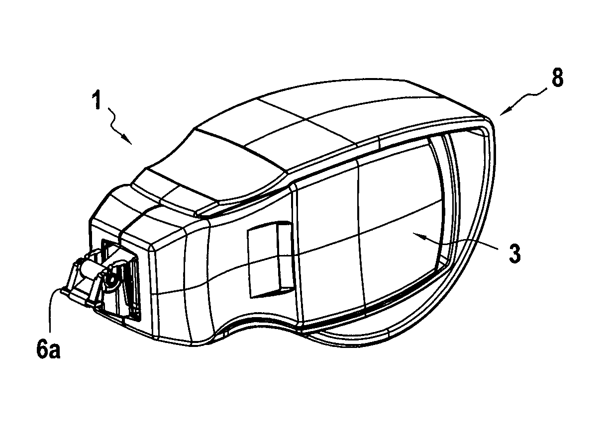
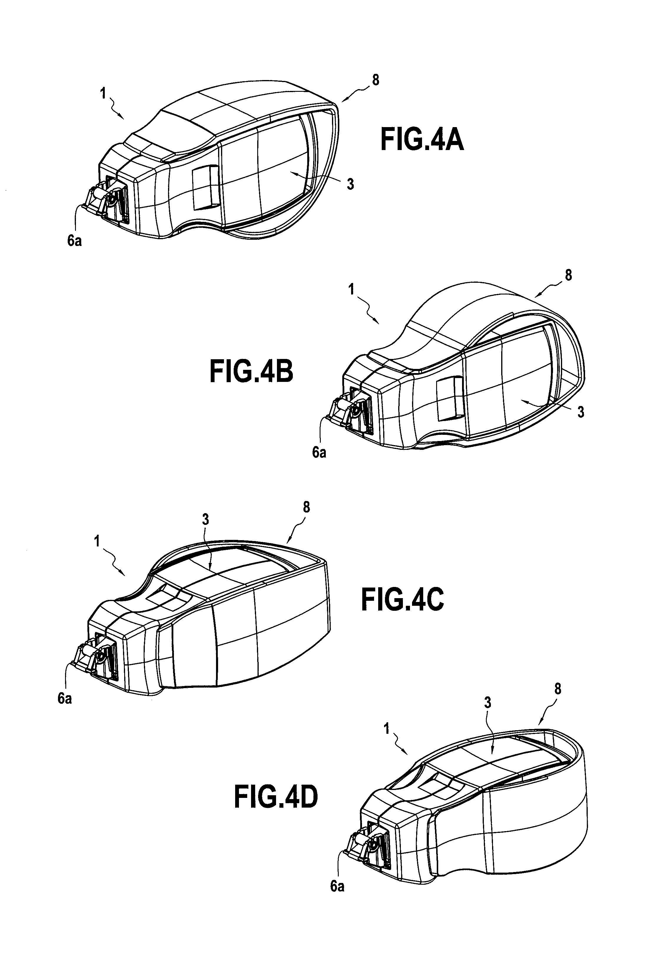
FIG. 4A is a perspective view of the manual applicator of the first embodiment with the handle in a first orientation on the housing;
FIG. 4B is a perspective view of the manual applicator of the first embodiment with the handle in a second orientation on the housing;
FIG. 4C is a perspective view of the manual applicator of the first embodiment with the handle in a third orientation on the housing;
FIG. 4D is a perspective view of the manual applicator of the first embodiment with the handle in a fourth orientation on the housing;
FIG. 5 is a longitudinal section view of a housing of a manual applicator in a second embodiment of the present invention;
FIG. 6 is a longitudinal section view of a handle for fastening on the FIG. 5 housing in order to form a manual applicator in a second embodiment of the present invention;
FIG. 7A is a side view of the FIG. 5 housing;
FIG. 7B is a top view of the FIG. 5 housing;
FIG. 8A is a perspective view of the manual applicator of the second embodiment with the handle in a first orientation on the housing;
FIG. 8B is a perspective view of the manual applicator of the second embodiment with the handle in a second orientation on the housing;
FIG. 8C is a perspective view of the manual applicator of the second embodiment with the handle in a third orientation on the housing; and
FIG. 8D is a perspective view of the manual applicator of the second embodiment with the handle in a fourth orientation on the housing.
DETAILED DESCRIPTION OF THE INVENTION
FIG. 1 shows the inside of a housing 3 of a manual applicator configured so as to enable a film to be transferred from a carrier tape 11 to a substrate. For this purpose, the applicator comprises, inside the housing 3, a feed spool 4 and a pickup spool 5 for the carrier tape. The applicator also has an applicator endpiece 6 projecting from a front opening 7 of the housing 3. The feed spool 4 is suitable for turning about a first axis of rotation X.sub.1 in order to unwind the carrier tape. The carrier tape 11 is picked up by the pickup spool 5, which is suitable for rotating about a second axis of rotation X.sub.2 that is substantially parallel to, but offset from, the first axis of rotation X.sub.1. Between the feed spool 4 and the pickup spool 5, the carrier tape is guided in front of a front edge 6a of the applicator endpiece 6. Thus, pressing the endpiece 6 against a substrate (not shown) such as a sheet of paper, for example, causes the film to be transferred from an outside face of the carrier tape onto the substrate. Friction of the outside face of the carrier tape against the substrate exerts traction on the carrier tape between the endpiece 6 and the feed spool 4, thereby causing the carrier tape, which is wound around the feed spool 4, to be unwound progressively. The applicator also has a belt 2 for transmitting rotation from the feed spool 4 to the pickup spool 5, thereby maintaining tension on the carrier tape between the endpiece 6 and the pickup spool. Nevertheless, as an alternative, it is possible to use other transmission means for this function, such as for example gearing.
FIG. 2 shows a handle 8 for releasably fastening on the housing 3. More specifically, the handle 8 is C-shaped with two longitudinal tabs 8e and 8f having proximal ends that are connected together by a transverse link segment 8g, which tabs present an internal outline 9 into which the housing 3 can be pressed. In this first embodiment, the internal outline 9 is formed in an inside portion 8a of the handle that is made of a relatively rigid material, and that is surrounded by an outside portion 8d of a material that is relatively flexible, presenting a grip surface 8c in order to facilitate a user gripping the handle 8. The terms "relatively rigid material" and "relatively flexible material" are used to mean that the first material presents a modulus of elasticity that is significantly greater than that of the second material. In this first embodiment, these two different materials may in particular both be thermoplastics, thus enabling the handle to be produced by injection molding, and in particular by co-injection of the two materials. Nevertheless, other materials and other production methods could also be envisaged.
As can be seen in FIG. 2, the internal outline 9 of the handle 8 is substantially symmetrical. The term "substantially symmetrical" is used in the present context to mean that this outline is as symmetrical as can be obtained at reasonable cost using the manufacturing technologies involved. In contrast, the external outline of the grip surface 8c is asymmetrical in order to make it particularly ergonomic to hold.
It can be seen in FIG. 3A that, in a longitudinal plane perpendicular to the front edge 6a of the applicator endpiece 6, the housing 3 presents an external outline 10 that is complementary to the internal outline 9 of the handle 8 and that is also substantially symmetrical. Thus, the housing 3 can be pressed into the inside of the handle 8 when oriented in this first plane. Nevertheless, and as can be seen in FIG. 3B, the housing 3 presents substantially the same external outline 10 in a longitudinal plane that is in alignment with the front edge 6a of the applicator endpiece 6. The housing 3 can thus also be pressed into the inside of the handle 8 in this second plane, perpendicular to the first. In addition, in both situations, since the external outlines 10 are symmetrical, the handle 8 can be fastened in two opposite alternative orientations in order to match the applicator endpiece 6 to users who are right-handed or left-handed.
In order to ensure that the handle 8 is fastened in stable manner on the housing 3, it presents protuberances 12, 13 respectively on the distal ends of the longitudinal tabs 8e, 8f and on the transverse link segments 8g. These protuberances 12 and 13 are oriented towards the inside of the handle 8 and they are configured so as to co-operate with complementary recesses 14 and 15 in the outside of the housing 3 in order to stabilize the handle 8 on the housing 3 by snap-fastening. Nevertheless, and alternatively, at least one of the protuberances could be situated on the housing and the handle could present a complementary recess.
FIG. 4A thus shows the applicator 1 with the handle 8 oriented in a longitudinal plane perpendicular to the front edge 6a of the applicator endpiece 6. In FIG. 4B, the handle 8 is likewise oriented in a longitudinal plane perpendicular to the front edge 6a of the applicator endpiece, but in an orientation that is opposite to that of FIG. 4A. In contrast, in FIG. 4C, the handle 8 is oriented in a longitudinal plane that is in alignment with the front edge 6a of the applicator endpiece 6. Finally, in FIG. 4D, the handle 8 is likewise oriented in a longitudinal plane that is in alignment with the front edge 6a of the applicator endpiece, but in an orientation that is opposite to that of FIG. 4C. In all four configurations, although the handle 8 is fastened to the housing 3 by forced locking due to its elastic deformation and the pressure it exerts on the external outline 10 and in the recesses 14, 15 of the housing 3, this connection is releasable, making it possible for the housing 3 to be replaced or to change the orientation of the handle 8 depending on the preferences of other users.
FIG. 5 shows the housing 3 of an applicator 1 in a second embodiment. Although different in detail, this housing 3 is substantially analogous to the housing of the first embodiment and equivalent elements are given the same reference numbers in the drawings.
In this second embodiment, the inside portion 8a of the handle 8, shown in FIG. 6, presents a core 8a' of relatively rigid material having overmolded thereon a relatively flexible material that also forms a cellular portion 8b and the outside portion 8d presenting the grip surface 8c. In this second embodiment, the core 8a' may be formed by at least one metal blade or cord folded into a C-shape with two tabs extending in the longitudinal tabs 8e, 8f of the handle 8. Nevertheless, other materials such as polymers or composites could equally well be considered for the core 8a'. The relatively flexible material that is overmolded on the core may in particular be a thermoplastic, thus enabling the handle to be produced by injection molding. Nevertheless, as an alternative, at least one of the protuberances could be situated on the housing and the handle could present a complementary recess.
The remaining elements of the handle 8 in this second embodiment are equivalent to those of the first embodiment and are therefore given the same reference numbers as in the figures showing the first embodiment.
FIGS. 7A and 7B show how the housing 3 in this second embodiment also presents substantially the same external outline in a first longitudinal section plane and in a second longitudinal section plane perpendicular to the first.
In a manner analogous to FIGS. 4A to 4D, FIGS. 8A to 8D show how the handle 8 of this second embodiment can thus likewise be fastened in releasable manner in the same orientations as in the first embodiment.
Although the present invention is described with reference to specific embodiments, it is clear that various modifications and changes can be made to those embodiments without going the general ambit of the invention as defined by the claims. In particular, although the invention is described with reference to a manual applicator having a carrier tape, it is equally applicable to other types of applicator, e.g. including applicators having an internal supply of fluid material and a porous applicator endpiece. In addition, individual characteristics of the various embodiments mentioned may be combined in additional embodiments. Consequently, the description and the drawings should be considered in a sense that is illustrative rather than restrictive.
* * * * *
D00000
D00001
D00002
D00003
D00004
XML
uspto.report is an independent third-party trademark research tool that is not affiliated, endorsed, or sponsored by the United States Patent and Trademark Office (USPTO) or any other governmental organization. The information provided by uspto.report is based on publicly available data at the time of writing and is intended for informational purposes only.
While we strive to provide accurate and up-to-date information, we do not guarantee the accuracy, completeness, reliability, or suitability of the information displayed on this site. The use of this site is at your own risk. Any reliance you place on such information is therefore strictly at your own risk.
All official trademark data, including owner information, should be verified by visiting the official USPTO website at www.uspto.gov. This site is not intended to replace professional legal advice and should not be used as a substitute for consulting with a legal professional who is knowledgeable about trademark law.