Force based touch interface with integrated multi-sensory feedback
Lisseman , et al.
U.S. patent number 10,241,579 [Application Number 15/867,226] was granted by the patent office on 2019-03-26 for force based touch interface with integrated multi-sensory feedback. This patent grant is currently assigned to JOYSON SAFETY SYSTEMS ACQUISITION LLC. The grantee listed for this patent is JOYSON SAFETY SYSTEMS ACQUISITION LLC. Invention is credited to David Andrews, Jason Lisseman.


| United States Patent | 10,241,579 |
| Lisseman , et al. | March 26, 2019 |
Force based touch interface with integrated multi-sensory feedback
Abstract
A force-based haptic switch panel, comprising a touch plate having first and second surfaces, the first surface comprising a touch surface and the second surface opposing the first surface. The haptic switch panel may also comprise a circuit board having a plurality of force sensors electrically coupled thereto. The force sensors are disposed between the circuit board and the second surface of the touch plate, wherein each force sensor is configured to measure a respective portion of a force applied to the touch surface of the touch plate. The haptic switch panel may also comprise an acoustic actuator disposed proximate a second surface of the touch plate and configured to generate a haptic output and an audible output responsive to the force applied to the touch surface.
| Inventors: | Lisseman; Jason (Shelby Township, MI), Andrews; David (Ortonville, MI) | ||||||||||
|---|---|---|---|---|---|---|---|---|---|---|---|
| Applicant: |
|
||||||||||
| Assignee: | JOYSON SAFETY SYSTEMS ACQUISITION
LLC (Auburn Hills, MI) |
||||||||||
| Family ID: | 52776556 | ||||||||||
| Appl. No.: | 15/867,226 | ||||||||||
| Filed: | January 10, 2018 |
Prior Publication Data
| Document Identifier | Publication Date | |
|---|---|---|
| US 20180203511 A1 | Jul 19, 2018 | |
Related U.S. Patent Documents
| Application Number | Filing Date | Patent Number | Issue Date | ||
|---|---|---|---|---|---|
| 14509493 | Oct 8, 2014 | 9898087 | |||
| 61888322 | Oct 8, 2013 | ||||
| 61891231 | Oct 15, 2013 | ||||
| Current U.S. Class: | 1/1 |
| Current CPC Class: | G06F 3/167 (20130101); G06F 3/0414 (20130101); G06F 3/0418 (20130101); B62D 1/04 (20130101); G06F 3/016 (20130101); G06F 2203/04104 (20130101); G06F 2203/04106 (20130101) |
| Current International Class: | G06F 3/01 (20060101); B62D 1/04 (20060101); G06F 3/041 (20060101); G06F 3/16 (20060101) |
References Cited [Referenced By]
U.S. Patent Documents
| 4484026 | November 1984 | Thornburg |
| 4540979 | September 1985 | Gerger et al. |
| 4801771 | January 1989 | Mizuguchi et al. |
| 4929934 | May 1990 | Ueda et al. |
| 5398962 | March 1995 | Kropp |
| 5408873 | April 1995 | Schmidt et al. |
| 5423569 | June 1995 | Reighard et al. |
| 5453941 | September 1995 | Yoshikawa |
| 5463258 | October 1995 | Filion et al. |
| 5539259 | July 1996 | Filion et al. |
| 5793297 | August 1998 | Takeuchi et al. |
| 5855144 | January 1999 | Parada |
| 5871063 | February 1999 | Young |
| 5914658 | June 1999 | Arakawa |
| 5943044 | August 1999 | Martinelli |
| 5965952 | October 1999 | Podoloff et al. |
| 6067077 | May 2000 | Martin |
| 6333736 | December 2001 | Sandbach |
| 6378384 | April 2002 | Atkinson et al. |
| 6429846 | August 2002 | Rosenberg et al. |
| 6501463 | December 2002 | Dahley et al. |
| 6636197 | October 2003 | Goldberg et al. |
| 6809462 | October 2004 | Pelrine et al. |
| 6906700 | June 2005 | Armstrong |
| 6933920 | August 2005 | Lacroix et al. |
| 7126583 | October 2006 | Breed |
| 7258026 | August 2007 | Papakostas et al. |
| 7336260 | February 2008 | Martin et al. |
| 7649278 | January 2010 | Yoshida et al. |
| 7808488 | October 2010 | Martin et al. |
| 7952498 | May 2011 | Higa |
| 7952566 | May 2011 | Poupyrev |
| 8022933 | September 2011 | Hardacker |
| 8059104 | November 2011 | Shahoian et al. |
| 8073501 | December 2011 | Tierling |
| 8188981 | May 2012 | Shahoian et al. |
| 8203454 | June 2012 | Knight et al. |
| 8204547 | June 2012 | Jang |
| 8214105 | July 2012 | Daly et al. |
| 8222799 | July 2012 | Polyakov et al. |
| 8237324 | August 2012 | Pei et al. |
| 8269731 | September 2012 | Molne |
| 8330590 | December 2012 | Poupyrev et al. |
| 8368566 | February 2013 | Higa |
| 8384679 | February 2013 | Paleczny et al. |
| 8384680 | February 2013 | Paleczny et al. |
| 8427441 | April 2013 | Paleczny et al. |
| 8614683 | December 2013 | Ng et al. |
| 8633916 | January 2014 | Bernstein |
| 8638308 | January 2014 | Cunningham et al. |
| 8686952 | April 2014 | Burrough et al. |
| 8698764 | April 2014 | Karakotsios |
| 8723810 | May 2014 | Kim |
| 9244562 | January 2016 | Rosenberg et al. |
| 9337832 | May 2016 | Buttolo |
| 9864507 | January 2018 | Cheng et al. |
| 9898087 | February 2018 | Lisseman |
| 2002/0041164 | April 2002 | Kim |
| 2002/0054060 | May 2002 | Schena |
| 2003/0043014 | March 2003 | Nakazawa et al. |
| 2003/0076968 | April 2003 | Rast |
| 2003/0083131 | May 2003 | Armstrong |
| 2003/0206162 | November 2003 | Roberts |
| 2004/0021643 | February 2004 | Hoshino et al. |
| 2004/0195031 | October 2004 | Nagasaka |
| 2004/0207605 | October 2004 | Mackey et al. |
| 2005/0021190 | January 2005 | Worrell et al. |
| 2005/0052426 | March 2005 | Hagermoser et al. |
| 2005/0063757 | March 2005 | Sugimura |
| 2005/0067889 | March 2005 | Chernoff |
| 2005/0110769 | May 2005 | DaCosta et al. |
| 2005/0156892 | July 2005 | Grant |
| 2005/0273218 | December 2005 | Breed et al. |
| 2006/0025897 | February 2006 | Shostak et al. |
| 2006/0054479 | March 2006 | Iisaka |
| 2006/0109256 | May 2006 | Grant |
| 2006/0113880 | June 2006 | Pei et al. |
| 2006/0177212 | August 2006 | Lamborghini et al. |
| 2006/0248478 | November 2006 | Liau |
| 2006/0262103 | November 2006 | Hu |
| 2006/0284839 | December 2006 | Breed |
| 2007/0062753 | March 2007 | Yoshida et al. |
| 2007/0097073 | May 2007 | Takashima et al. |
| 2007/0100523 | May 2007 | Trachte |
| 2007/0129046 | June 2007 | Soh |
| 2007/0287494 | December 2007 | You et al. |
| 2008/0012837 | January 2008 | Marriott et al. |
| 2008/0062145 | March 2008 | Shahoian |
| 2008/0079604 | April 2008 | Madonna et al. |
| 2008/0150911 | June 2008 | Harrison |
| 2008/0202912 | August 2008 | Boddie et al. |
| 2008/0230283 | September 2008 | Yoon |
| 2009/0001855 | January 2009 | Lipton |
| 2009/0020343 | January 2009 | Rothkopf et al. |
| 2009/0051667 | February 2009 | Park et al. |
| 2009/0114518 | May 2009 | Lin et al. |
| 2009/0125811 | May 2009 | Bethurum |
| 2009/0140994 | June 2009 | Tanaka et al. |
| 2009/0140996 | June 2009 | Takashima et al. |
| 2009/0151447 | June 2009 | Jin et al. |
| 2009/0153340 | June 2009 | Pinder et al. |
| 2009/0160529 | June 2009 | Lamborghini |
| 2009/0189749 | July 2009 | Salada |
| 2009/0228791 | September 2009 | Kim et al. |
| 2009/0237374 | September 2009 | Li et al. |
| 2009/0241378 | October 2009 | Ellis |
| 2010/0001974 | January 2010 | Su et al. |
| 2010/0045612 | February 2010 | Molne |
| 2010/0053087 | March 2010 | Dai |
| 2010/0066512 | March 2010 | Rank |
| 2010/0141410 | June 2010 | Aono et al. |
| 2010/0141606 | June 2010 | Bae et al. |
| 2010/0156814 | June 2010 | Weber et al. |
| 2010/0156823 | June 2010 | Paleczny et al. |
| 2010/0168998 | July 2010 | Matsunaga |
| 2010/0200375 | August 2010 | Han et al. |
| 2010/0226075 | September 2010 | Jahge |
| 2010/0231540 | September 2010 | Cruz-Hernandez et al. |
| 2010/0236911 | September 2010 | Wild et al. |
| 2010/0250066 | September 2010 | Eckstein et al. |
| 2010/0250071 | September 2010 | Pala et al. |
| 2010/0268426 | October 2010 | Pathak |
| 2010/0302177 | December 2010 | Kim et al. |
| 2010/0315267 | December 2010 | Chung et al. |
| 2010/0321310 | December 2010 | Kim et al. |
| 2010/0321335 | December 2010 | Lim et al. |
| 2010/0328112 | December 2010 | Liu |
| 2011/0037721 | February 2011 | Cranfill et al. |
| 2011/0046788 | February 2011 | Daly et al. |
| 2011/0054359 | March 2011 | Sazonov et al. |
| 2011/0069021 | March 2011 | Hill |
| 2011/0109552 | May 2011 | Yasutake |
| 2011/0141052 | June 2011 | Bernstein et al. |
| 2011/0148608 | June 2011 | Grant et al. |
| 2011/0175844 | July 2011 | Berggren |
| 2011/0205081 | August 2011 | Chen |
| 2011/0210926 | September 2011 | Pasquero |
| 2011/0216015 | September 2011 | Edwards |
| 2011/0216027 | September 2011 | Kim et al. |
| 2011/0227872 | September 2011 | Huska |
| 2011/0241850 | October 2011 | Bosch et al. |
| 2011/0245992 | October 2011 | Stahlin et al. |
| 2011/0248728 | October 2011 | Maruyama |
| 2011/0260983 | October 2011 | Pertuit et al. |
| 2011/0267181 | November 2011 | Kildal |
| 2011/0279380 | November 2011 | Weber et al. |
| 2011/0290038 | December 2011 | Hoshino et al. |
| 2012/0038468 | February 2012 | Provancher |
| 2012/0039494 | February 2012 | Ellis |
| 2012/0062491 | March 2012 | Coni et al. |
| 2012/0105367 | May 2012 | Son et al. |
| 2012/0120009 | May 2012 | Lussey et al. |
| 2012/0126959 | May 2012 | Zarrabi et al. |
| 2012/0127115 | May 2012 | Gannon |
| 2012/0169663 | July 2012 | Kim et al. |
| 2012/0223900 | September 2012 | Jiyama et al. |
| 2012/0229424 | September 2012 | Behles |
| 2012/0267221 | October 2012 | Gohng et al. |
| 2012/0267222 | October 2012 | Gohng et al. |
| 2012/0296528 | November 2012 | Wellhoefer et al. |
| 2012/0299856 | November 2012 | Hasui |
| 2013/0016053 | January 2013 | Jung et al. |
| 2013/0063380 | March 2013 | Wang et al. |
| 2013/0063389 | March 2013 | Moore |
| 2013/0093679 | April 2013 | Dickinson et al. |
| 2013/0096849 | April 2013 | Campbell et al. |
| 2013/0106691 | May 2013 | Rank |
| 2013/0113715 | May 2013 | Grant et al. |
| 2013/0113717 | May 2013 | Van Eerd et al. |
| 2013/0128587 | May 2013 | Lisseman et al. |
| 2013/0141396 | June 2013 | Lynn et al. |
| 2013/0147284 | June 2013 | Chun |
| 2013/0154938 | June 2013 | Arthur et al. |
| 2013/0181931 | July 2013 | Kinoshita |
| 2013/0218488 | August 2013 | Grandemanage et al. |
| 2013/0222287 | August 2013 | Bae et al. |
| 2013/0222310 | August 2013 | Birnbaum et al. |
| 2013/0228023 | September 2013 | Drasnin et al. |
| 2013/0250502 | September 2013 | Tossavainen |
| 2013/0257776 | October 2013 | Tissot |
| 2013/0265273 | October 2013 | Marsden et al. |
| 2013/0307788 | November 2013 | Rao et al. |
| 2013/0342337 | December 2013 | Kiefer et al. |
| 2014/0071060 | March 2014 | Santos-Gomez |
| 2014/0090505 | April 2014 | Okuyama et al. |
| 2014/0092025 | April 2014 | Pala et al. |
| 2014/0191973 | July 2014 | Zellers |
| 2014/0267076 | September 2014 | Birnbaum et al. |
| 2014/0267113 | September 2014 | Lisseman et al. |
| 2014/0267114 | September 2014 | Lisseman et al. |
| 2015/0009164 | January 2015 | Shinozaki et al. |
| 2015/0009168 | January 2015 | Olien et al. |
| 2015/0046825 | February 2015 | Li |
| 2015/0116205 | April 2015 | Westerman et al. |
| 2015/0212571 | July 2015 | Kitada |
| 2015/0309576 | October 2015 | Tissot |
| 2016/0109949 | April 2016 | Park |
| 2016/0216764 | July 2016 | Morrell |
| 2017/0075424 | March 2017 | Bernstein |
| 1607850 | Dec 2005 | EP | |||
| 06-037056 | May 1994 | JP | |||
| 2005-175815 | Jun 2005 | JP | |||
| 2000-71809 | Mar 2007 | JP | |||
| 2008-181709 | Aug 2008 | JP | |||
| 2011-3188 | Jan 2011 | JP | |||
| 2012-064210 | Mar 2012 | JP | |||
| 2012-73785 | Apr 2012 | JP | |||
| 2012-150833 | Aug 2012 | JP | |||
| 2012176640 | Sep 2012 | JP | |||
| 1020060047110 | May 2006 | KR | |||
| 1020100129424 | Dec 2010 | KR | |||
| 01/88935 | Nov 2001 | WO | |||
| 2011008292 | Jan 2011 | WO | |||
| 2012052635 | Apr 2012 | WO | |||
| 2012169229 | Dec 2012 | WO | |||
| 2013082293 | Jun 2013 | WO | |||
| 2015054354 | Apr 2015 | WO | |||
| 2015054364 | Apr 2015 | WO | |||
| 2015054369 | Apr 2015 | WO | |||
| 2015054373 | Apr 2015 | WO | |||
| 2014194192 | Dec 2015 | WO | |||
Other References
|
International Search Report and Written Opinion issued in related International Application No. PCT/US2014/059652 dated Dec. 22, 2014. cited by applicant . International Preliminary Report on Patentability and Written Opinion, dated Apr. 12, 2016, received in connection with International Patent Application No. PCT/US2014/059652. cited by applicant . International Search Report and Written Opinion issued in related International Application No. PCT/US2014/059673 dated Jan. 9, 2015. cited by applicant . International Preliminary Report on Patentability and Written Opinion, dated Apr. 12, 2016, received in connection with International Patent Application No. PCT/US2014/059673. cited by applicant . International Search Report and Written Opinion issued in related International Application No. PCT/2014/059669 dated Jan. 23, 2015. cited by applicant . International Preliminary Report on Patentability and Written Opinion, dated Apr. 21, 2016, received in connection with International Patent Application No. PCT/US2014/059669. cited by applicant . International Search Report and Written Opinion issued in related International Application No. PCT/US2014/059657 dated Feb. 16, 2015. cited by applicant . International Preliminary Report on Patentability and Written Opinion, dated Apr. 12, 2016, received in connection with International Patent Application No. PCT/US2014/059657. cited by applicant . International Search Report and Written Opinion issued in related International Application No. PCT/US2014/059639 dated Feb. 24, 2015. cited by applicant . International Preliminary Report on Patentability and Written Opinion, dated Apr. 12, 2016, received in connection with International Patent Application No. PCT/US2014/059639. cited by applicant . International Search Report and Written Opinion issued in related International Application No. PCT/US2014/040224 dated Sep. 24, 2014. cited by applicant . International Preliminary Report on Patentability and Written Opinion, issued in related Application No. PCT/US2014/040224 dated Dec. 10, 2015. cited by applicant . Office Action dated Dec. 17, 2015, received in connection with U.S. Appl. No. 14/211,475. cited by applicant . Office Action dated Dec. 15, 2015, received in connection with U.S. Appl. No. 14/211,665. cited by applicant . Office Action dated Apr. 21, 2016, received in connection with U.S. Appl. No. 14/028,798. cited by applicant . Office Action dated Oct. 8, 2015, received in connection with U.S. Appl. No. 14/028,798. cited by applicant . Co-pending Utility U.S. Appl. No. 14/509,535, filed Oct. 8, 2014, and its prosecution history. Issued as U.S. Pat. No. 9,513,707 on Dec. 6, 2016. cited by applicant . Office Action dated Feb. 11, 2016, received in connection with U.S. Appl. No. 14/509,535. cited by applicant . Notice of Allowance received in connection with U.S. Appl. No. 14/509,535, dated Aug. 3, 2016. cited by applicant . Co-pending Utility U.S. Appl. No. 14/509,332, filed Oct. 8, 2014, and its prosecution history. cited by applicant . Office Action dated May 3, 2016, received in connection with U.S. Appl. No. 14/509,332. cited by applicant . Office Action dated Oct. 27, 2016, received in connection with U.S. Appl. No. 14/509,332. cited by applicant . Office Action dated Feb. 8, 2018, received in connection with U.S. Appl. No. 14/509,332. cited by applicant . Office Action dated Jun. 14, 2016, received in connection with U.S. Appl. No. 14/509,462, filed Oct. 8, 2014 and its prosecution history. cited by applicant . Office Action issued in co-pending U.S. Appl. No. 14/509,462, dated Dec. 28, 2016. cited by applicant . Office Action issued in co-pending U.S. Appl. No. 14/509,462, dated Jun. 9, 2017. cited by applicant . Office Action issued in co-pending U.S. Appl. No. 14/509,462, dated Nov. 24, 2017. cited by applicant . Notice of Allowance issued in co-pending U.S. Appl. No. 14/509,462, dated Feb. 22, 2018. cited by applicant . Co-pending Utility U.S. Appl. No. 14/509,560, filed Oct. 8, 2014, and its prosecution history. Issued as U.S. Pat. No. 9,829,980 on Nov. 28, 2017. cited by applicant . Office Action issued in U.S. Appl. No. 14/509,560, dated Feb. 10, 2017. cited by applicant . Corrected Notice of Allowance issued in U.S. Appl. No. 14/509,560, dated Aug. 22, 2017. cited by applicant . Notice of Allowance issued in U.S. Appl. No. 14/509,560, dated Aug. 10, 2017. cited by applicant . Co-pending Utility U.S. Appl. No. 15/822,868, filed Nov. 27, 2017. cited by applicant . Office Action issued in U.S. Appl. No. 15/230,786, dated Feb. 7, 2017. cited by applicant . Office Action issued in U.S. Appl. No. 15/230,786, dated Aug. 24, 2017. cited by applicant . Co-pending Utility U.S. Appl. No. 14/509,598, filed Oct. 8, 2014 and its prosecution history. cited by applicant . Office Action issued in U.S. Appl. No. 14/509,598, dated Jan. 6, 2017. cited by applicant . Office Action issued in U.S. Appl. No. 14/509,598, dated Oct. 17, 2017. cited by applicant . Office Action dated Nov. 4, 2014, received in connection with JP Patent Application No. 2011-075258. (English Translation attached). cited by applicant . U.S. Appl. No. 13/076,226, filed Mar. 30, 2011, and issued as U.S. Pat. No. 9,007,190 on Apr. 14, 2015, and its file history. cited by applicant . Office Action dated Mar. 11, 2013 in U.S. Appl. No. 13/076,226, now U.S. Pat. No. 9,007,190 on Apr. 14, 2015. cited by applicant . Office Action dated Feb. 13, 2014 in U.S. Appl. No. 13/076,226, now U.S. Pat. No. 9,007,190 on Apr. 14, 2015. cited by applicant . Office Action dated Sep. 11, 2014 in U.S. Appl. No. 13/076,226, now U.S. Pat. No. 9,007,190 on Apr. 14, 2015. cited by applicant . Co-pending Utility U.S. Appl. No. 14/291,845, filed May 30, 2014 and its prosecution history. cited by applicant . Office Action dated Sep. 24, 2015 in U.S. Appl. No. 14/291,845. cited by applicant . Office Action dated Feb. 24, 2016, received in connection with U.S. Appl. No. 14/291,845. cited by applicant . Office Action dated Feb. 3, 2017, received in connection with U.S. Appl. No. 14/291,845. cited by applicant . Office Action dated Aug. 24, 2017, received in connection with U.S. Appl. No. 14/291,845. cited by applicant . Office Action dated Feb. 26, 2018, received in connection with Chinese Application No. 201480030786. (English Translation attached). cited by applicant . First Office Action issued for Chinese Application No. 201480055484.8, dated May 31, 2018. cited by applicant . First Office Action issued for Japanese Application No. 2016-517039, dated Jun. 26, 2018. cited by applicant . First Office Action issued for Japanese Application No. 2016-520148, dated Jul. 3, 2018. cited by applicant . Notice of allowance issued in co-pending U.S. Appl. No. 14/509,493, dated Oct. 10, 2017. cited by applicant . Non-Final Office Action, dated May 17, 2017, in connection to U.S. Appl. No. 14/509,598. cited by applicant . Notice of Allowance issued for U.S. Appl. No. 14/509,332, dated Sep. 7, 2018. cited by applicant . Applicant-Initiated Interview Summary issued for U.S. Appl. No. 14/509,598, dated Sep. 18, 2018, 5 pages. cited by applicant . Office Action issued for U.S. Appl. No. 14/509,598, dated Jan. 18, 2019. cited by applicant. |
Primary Examiner: Haley; Joseph R
Assistant Examiner: Frank; Emily J
Attorney, Agent or Firm: Meunier Carlin & Curfman LLC
Parent Case Text
CROSS-REFERENCE TO RELATED APPLICATION
This application is a continuation application of U.S. application Ser. No. 14/509,493 filed Oct. 8, 2014, now U.S. Pat. No. 9,898,087 issued Feb. 20, 2018, which claims the benefit of U.S. Provisional Application No. 61/888,322, filed Oct. 8, 2013, and U.S. Provisional Application No. 61/891,231, filed Oct. 15, 2013, each of which are incorporated herein by reference in their entireties.
Claims
What is claimed is:
1. A force-based haptic switch panel, comprising: a touch plate having first and second surfaces, the first surface comprising a touch surface and the second surface opposing the first surface; a circuit board having a plurality of force sensors electrically coupled thereto, the force sensors disposed between the circuit board and the second surface of the touch plate, wherein each force sensor generates an electrical signal that is proportional to a magnitude of a respective portion of a force received by each force sensor in response to the force being applied to the touch surface of the touch plate; a processor, electrically coupled to the circuit board, wherein the processor is configured to determine a position of the force applied to the touch surface based on the electrical signals generated by the force sensors; and an actuator disposed proximate a central portion of a second surface of the touch plate to generate one or both of a haptic output and an audible output responsive to the force applied to the touch surface, wherein the central portion of the second surface is spaced apart from a perimeter of the touch plate.
2. The force-based haptic switch panel of claim 1, wherein the actuator comprises an audio speaker affixed to the second surface of the touch surface and configured to deliver one or both of the haptic output and the audible output to the touch plate.
3. The force-based haptic switch panel of claim 1, wherein the processor is configured to provide a plurality of different control signals for causing the actuator to generate one or both of the haptic and the audible outputs, each control signal associated with a respective force value applied to the touch surface or the position of the force applied to the touch surface.
4. The force-based haptic switch panel of claim 3, wherein the processor is further configured to cause the actuator to generate the haptic output and the audible output substantially simultaneously, in response to the force applied to the touch surface.
5. The force-based haptic switch panel of claim 3, wherein each control signal is configured to cause the actuator to generate a respective combination of tactile vibration and audible output.
6. The force-based haptic switch panel of claim 1, wherein the actuator is secured directly to the second surface.
7. The force-based haptic switch panel of claim 1, wherein a magnitude of at least one of the haptic output or the audible output is proportional to the magnitude of force applied to the touch surface.
8. The force-based haptic switch panel of claim 1, wherein a magnitude of at least one of the haptic output or the audible output is proportional to the position of the force applied to the touch surface.
9. The force-based haptic switch panel of claim 1, wherein each force sensor is at least in partial contact with the second surface of the touch plate and the circuit board prior to any force being applied to the touch surface.
10. A steering wheel, comprising: a force-based haptic switch panel embedded within at least a portion of the steering wheel, the force-based haptic switch panel comprising: a touch plate having first and second surfaces, the first surface comprising a touch surface and the second surface opposing the first surface, wherein the first surface of the touch plate is substantially flush with a surface of the steering wheel; a circuit board having a plurality of force sensors electrically coupled thereto, the force sensors disposed between the circuit board and the second surface of the touch plate, wherein each force sensor generates an electrical signal that is proportional to a magnitude of a respective portion of a force received by each force sensor in response to the force being applied to the touch surface of the touch plate; a processor, electrically coupled to the circuit board, wherein the processor is configured to determine a position of the force applied to the touch surface based on the electrical signals generated by the force sensors; and an actuator disposed proximate a central portion of a second surface of the touch plate to generate one or both of a haptic output and an audible output responsive to the force applied to the touch surface, wherein the central portion of the second surface is spaced apart from a perimeter of the touch plate.
11. The steering wheel of claim 10, wherein the actuator comprises an audio speaker affixed to the second surface of the touch surface and configured to deliver one or both of the haptic output and the audible output to the touch plate.
12. The steering wheel of claim 10, wherein the processor is configured to provide a plurality of different control signals for causing the actuator to generate one or both of the haptic and the audible outputs, each control signal associated with a respective force value applied to the touch surface or the position of the force applied to the touch surface.
13. The steering wheel of claim 12, wherein the processor is further configured to cause the actuator to generate the haptic output and the audible output substantially simultaneously, in response to the force applied to the touch surface.
14. The steering wheel of claim 12, wherein each control signal is configured to cause the actuator to generate a respective combination of tactile vibration and audible output.
15. The steering wheel of claim 10, wherein the actuator is secured directly to the second surface.
16. The steering wheel of claim 10, wherein a magnitude of at least one of the haptic output or the audible output is proportional to the magnitude of force applied to the touch surface.
17. The steering wheel of claim 10, wherein a magnitude of at least one of the haptic output or the audible output is proportional to the position of the force applied to the touch surface.
18. A vehicle, comprising: one or more ground-engaging devices; a steering interface, coupled to one or more ground-engaging devices and comprising a rim portion and a hub portion, the rim portion configured for grasping by an operator of a vehicle; a force-based haptic switch panel comprising: a touch plate having first and second surfaces, the first surface comprising a touch surface and the second surface opposing the first surface; a circuit board having a plurality of force sensors electrically coupled thereto, the force sensors disposed between the circuit board and the second surface of the touch plate, wherein each force sensor generates an electrical signal that is proportional to a magnitude of a respective portion of a force received by each force sensor in response to the force being applied to the touch surface of the touch plate; and an actuator disposed proximate a central portion of a second surface of the touch plate to generate one or both of a haptic output and an audible output responsive to the force applied to the touch surface, wherein the central portion of the second surface is spaced apart from a perimeter of the touch plate; and a processor, communicatively coupled to the actuator and the plurality of force sensors, wherein the processor is configured to determine a position of the force applied to the touch surface based on the electrical signals generated by the force sensors and wherein the processor provides a plurality of different control signals for causing the actuator to generate one or both of the haptic and audible outputs, each control signal associated with a respective force value applied to the touch surface or the position of the force applied to the touch surface.
19. The vehicle of claim 18, wherein the actuator comprises an audio speaker affixed to the second surface of the touch surface and deliver one or both of the haptic output and the audible output to the touch plate.
20. The vehicle of claim 18, wherein the processor is further configured to cause the actuator to generate the haptic output and the audible output substantially simultaneously, in response to the force applied to the touch surface.
21. The vehicle of claim 18, wherein each control signal is configured to cause the actuator to generate a respective combination of tactile vibration and audible output.
22. The vehicle of claim 18, wherein the actuator is secured directly to the second surface.
23. The vehicle of claim 18, wherein a magnitude of at least one of the haptic output of the audible output is proportional to the magnitude of force applied to the touch surface.
24. The vehicle of claim 18, wherein a magnitude of at least one of the haptic output or the audible output is proportional to the position of the force applied to the touch surface.
Description
TECHNICAL FIELD
The present disclosure relates generally to a tactile haptic switch panel and, more particularly, to force-based touch interfaces with integrated audible, haptic, and visual feedback.
BACKGROUND
The recent widespread growth of feature-rich, relatively portable, and user-friendly consumer electronic devices has sparked a corresponding consumer demand for implementation of similar functionality in conventional appliances and utilitarian devices. For example, more consumers are demanding modern touchscreen interfaces in utility appliances like televisions, refrigerators, dishwashers, and washing machines. Even modern thermostats are integrating gesture-controllable, fully-networked and remotely accessible user interfaces (UIs). Even the automobile, often thought of as the quintessential utilitarian machine, has not been impervious to recent trends to incorporate as many options and features accessible to the driver as possible--from mechanical switch controls for climate, navigation, and radio systems integrated into the steering wheel, to touchscreen interfaces and camera displays integrated into the dashboard.
Although consumer demand for incorporating greater functionality into the automotive driving experience is growing rapidly, there are a number of problems with meeting such demand. First, conventional capacitive sense touchscreen technologies, such as those used in smartphones and tablet devices, while ideal for incorporating a large amount of functionality in a relatively limited space, require significant visual engagement by the driver and are therefore too distracting to be implemented safely. Second, while the conventional mechanical switches and knobs that are currently in use are less distracting because they can be safely used without requiring the driver to remove his eyes from the road, they tend to have limited flexibility, with each switch controlling a single function or feature.
One solution for combining the flexibility and versatility of touchscreen technologies while still allowing the driver to remain attentive for safely operating the vehicle involves the use of force-based haptic human-machine interfaces (HMIs). Force-based haptic HMIs typically include a sensor surface that is responsive to touch and an actuator for generating a responsive vibration (often simulating the response provided by a mechanical switch) that provides the driver with a tactile confirmation of an input on the touchscreen. These systems incorporate the haptic feedback that drivers have come to rely on of mechanical switches with the multi-touch, multifunction flexibility of touchscreen controls.
One problem with force-based haptic HMIs, particularly in automobiles and other mechanical systems, is that accidental or inadvertent touches are much more common due to the inability of the driver to continuously view with the touch interface while driving. As a result, conventional interfaces that rely exclusively on a single sensory feedback response (e.g., visible displays) tend to be ineffective in situations where a user is unable to completely focus on the HMI. Furthermore, packaging issues associated with including multiple sensory feedback capabilities tend to require a significant amount of packaging area to accommodate the hardware needed to support multiple sensory output. Thus, a switch panel for including capabilities for stimulating multiple senses, while limiting packaging size would be particular advantageous.
The presently disclosed force-based touch interface with integrated multi-sensory feedback are directed to overcoming one or more of the problems set forth above and/or other problems in the art.
SUMMARY
According to one aspect, the present disclosure is directed to a force-based haptic switch panel, comprising a touch plate having first and second surfaces, the first surface comprising a touch surface and the second surface opposing the first surface. The force-based haptic switch panel may also include a circuit board having a plurality of force sensors electrically coupled thereto, the force sensors disposed between the circuit board and the second surface of the touch plate, wherein each force sensor is configured to measure a respective portion of a force applied to the touch surface of the touch plate. The force-based haptic switch panel may also include an acoustic actuator disposed proximate a second surface of the touch plate and configured to generate a haptic output and an audible output responsive to the force applied to the touch surface.
In accordance with another aspect, the present disclosure is directed to a steering wheel, comprising a force-based haptic switch panel embedded within at least a portion of the steering wheel. The force-based haptic switch panel may comprise a touch plate having first and second surfaces, the first surface comprising a touch surface and the second surface opposing the first surface. The first surface of the touch plate is substantially flush with a surface of the steering wheel. The force-based haptic switch panel may also comprise a circuit board having a plurality of force sensors electrically coupled thereto, the force sensors disposed between the circuit board and the second surface of the touch plate, wherein each force sensor is configured to measure a respective portion of a force applied to the touch surface of the touch plate. The force-based haptic switch panel may further comprise an acoustic actuator disposed proximate a second surface of the touch plate and configured to generate a haptic output and an audible output responsive to the force applied to the touch surface.
In accordance with another aspect, the present disclosure is directed to a vehicle comprising one or more ground-engaging devices and a steering interface, coupled to one or more ground-engaging devices and comprising a rim portion and a hub portion, the rim portion configured for grasping by an operator of a vehicle. The vehicle may also comprise a touch plate having first and second surfaces, the first surface comprising a touch surface and the second surface opposing the first surface. The vehicle may further comprise a circuit board having a plurality of force sensors electrically coupled thereto, the force sensors disposed between the circuit board and the second surface of the touch plate, wherein each force sensor is configured to measure a respective portion of a force applied to the touch surface of the touch plate. The vehicle may also comprise an acoustic actuator disposed proximate a second surface of the touch plate and configured to generate a haptic output and an audible output responsive to the force applied to the touch surface. The vehicle may further comprise a processor, communicatively coupled to the actuator and the plurality of force sensors. The processor may be configured to provide a plurality of different control signals for causing the acoustic actuator to generate the haptic and audible outputs, each haptic control signal associated with a respective force value applied to the touch surface.
BRIEF DESCRIPTION OF THE DRAWINGS
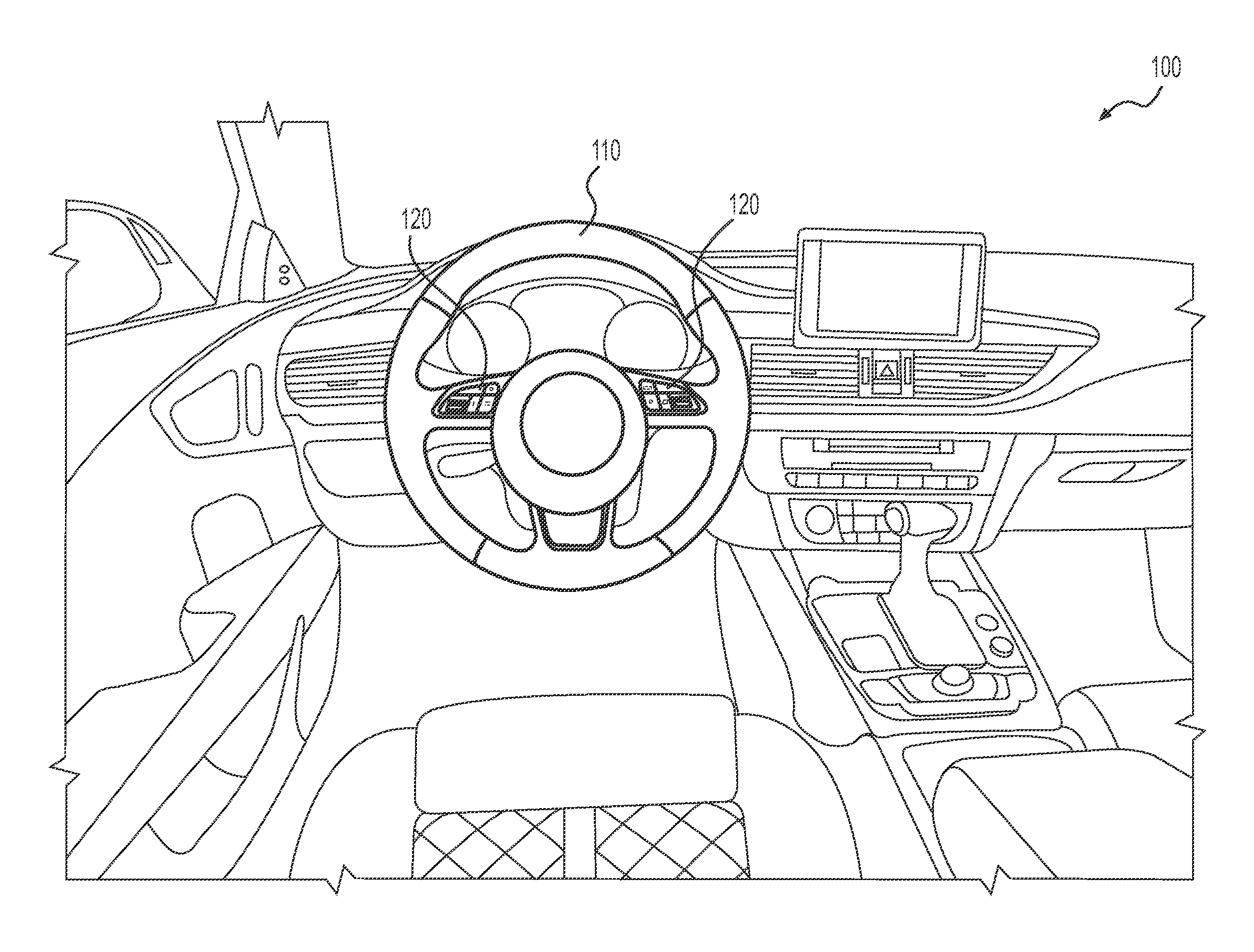
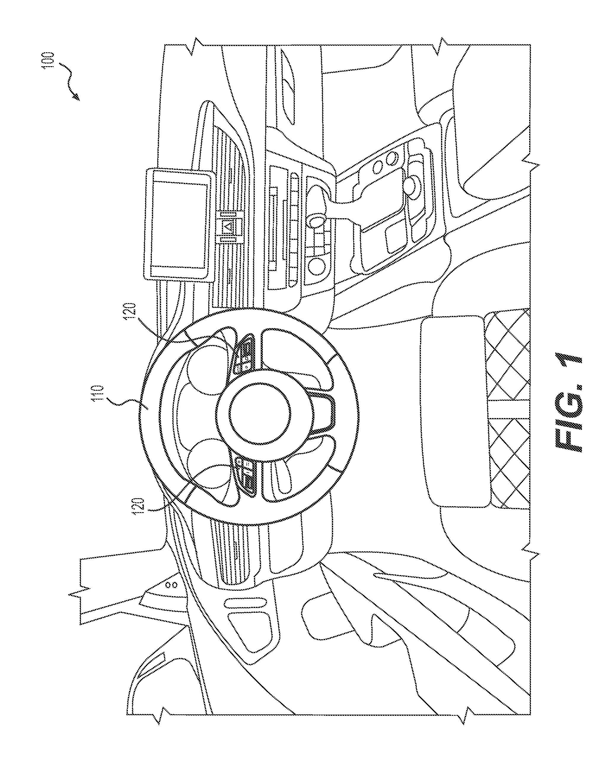
FIG. 1 illustrates an exemplary environment in which a tactile haptic switch panel consistent with certain disclosed embodiments may be implemented;
FIG. 2 illustrates an exemplary touch surface associated with a tactile haptic switch panel that is mounted within or upon a steering interface for a vehicle, in accordance with certain disclosed embodiments;
FIGS. 3A and 3B illustrate exemplary graphical layouts for one or more touch surfaces for a tactile haptic switch panel, consistent with certain disclosed embodiments;
FIG. 4 provides a prospective exploded view of certain structural and functional layers of a tactile haptic switch patent, in accordance with certain disclosed embodiments;
FIG. 5 provides alternative prospective exploded views of certain structural and functional layers of a tactile haptic switch patent, in accordance with certain disclosed embodiments;
FIG. 6 provides a cross-sectional block diagram of certain exemplary components associated with a tactile haptic switch panel, consistent with certain disclosed embodiments;
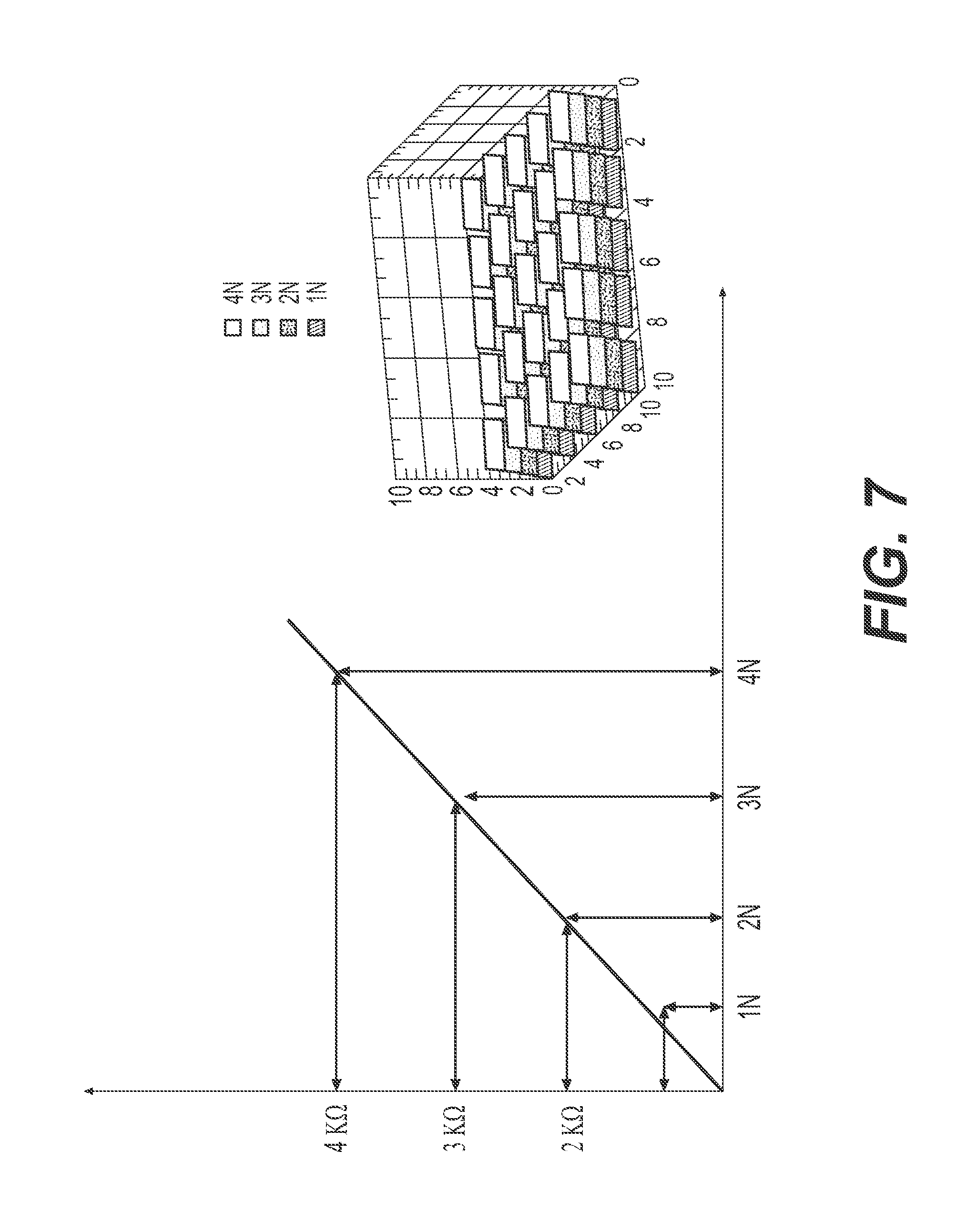
FIG. 7 provides graphs depicting exemplary force and location configuration values associated with a user interface layout for a multi-function tactile haptic switch panel, in accordance with certain disclosed embodiments; and
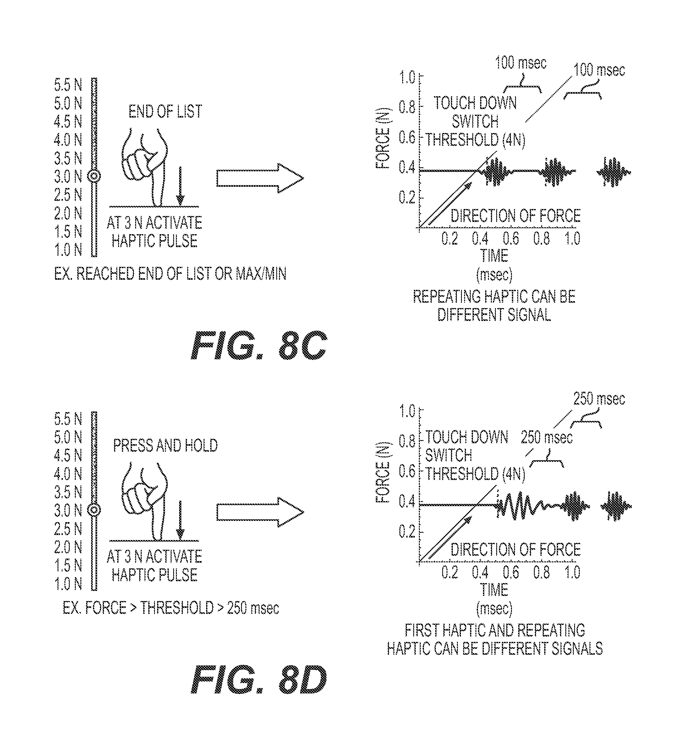
FIGS. 8A, 8B, 8C, and 8D provide graphs illustrating exemplary tactile feedback responses for different touch events (e.g., touch-down (e.g, engage), lift-off (e.g., release), end-of-list, and press-and-hold, respectively) associated with an exemplary multi-function tactile haptic switch panel, consistent with certain disclosed embodiments.
DETAILED DESCRIPTION
In accordance with one aspect, the present disclosure is directed to a force-based haptic switch panel that is configured to limit or lock the input area of a touch panel surface around an area associated with an initial touch detected at the surface. Accordingly, systems and methods consistent with the disclosed embodiments are configured to limit inadvertent or accidental touches by localizing the input area around an initial touch area. In certain exemplary embodiments, areas or regions that are not associated with initial touch area may be disabled, ensuring that stray or accidental touch inputs are not registered as inputs to the touch panel.
Methods and systems consistent with the disclosed embodiments may be particularly applicable in situations in which distractions divert the user's visual attention to the touch interface. Indeed, in certain disclosed embodiments, the present disclosure is directed to switch panel user interfaces that provide multi-sensory confirmations of user interactions with the switch panel. In certain other embodiments, features consistent with the present disclosure provide a solution for limiting the functional detection area to a smaller, more localized area surrounding an initial touch event.
FIG. 1 illustrates an exemplary operational environment 100 in which features and methods associated with the disclosed self-calibrating tactile haptic multi-touch, multifunction switch panel may be implemented. According to one embodiment, and as illustrated in FIG. 1, operational environment 100 may include or embody a driver seat or cockpit associated with the vehicle, such as a ground-based motor vehicle. Alternatively, or additionally, operational environment 100 may include or embody a driver console associated with any land, air, or sea-based transportation vehicle in which, such as a watercraft, aircraft, conventional motor vehicle, off-road vehicle, heavy construction machine, or any other type of vehicle. It is also contemplated that the presently disclosed embodiments may be employed in any stationary machine having a user console or interface, as a replacement for a conventional mechanical switch or button, such as, for example, in a vehicle training simulator, a video game console, or any other type of system that requires a human-machine interface.
FIG. 1 illustrates a plan view of an exemplary steering interface implementing a force-based switch panel (also referred to herein as a track pad interface) for vehicle control panels in accordance with the present disclosure. An example steering interface 110 can have a steering grip. A steering grip can be shaped in such a way to facilitate a driver's control of a vehicle when holding the steering grip. For example, the steering grip can include an annular ring shape with an outer contour that is essentially circular in shape. In an alternate implementation, the steering grip can define any suitable shape including, for example, circular, elliptical, square, rectangular, or any other regular or irregular shape. In an exemplary implementation, the steering grip can include a single continuous grip portion or any number of unique grip sections. Additionally, the steering grip can be mounted on a fixed component such that it can be rotationally moved about a steering axis. An exemplary fixed component can include, for example, a steering column, which receives a steering spindle that extends along the steering column and serves to transmit the rotational movement of the steering grip to the wheels of the motor vehicle. Rotational movement of the steering grip may be transmitted to the wheels by mechanical and/or electrical means. In an exemplary implementation, the steering interface 110 can also include a one or more force-based tactile haptic switch panels 120, wherein each of the force-based switch panels 120 is operably coupled to the steering interface 110.
Coupling force-based switch panels 120 to the steering interface 110 provides a driver with a human-machine interface that can be configured to detect a touch or force provided by a user and determine if a switch function should or should not be activated, for example. In one embodiment, the user can be provided with a tactile or audible feedback in response to the detected input.
FIG. 2 illustrates a zoom view of an exemplary steering interface 110 having embedded therein a force-based switch panel 120 consistent with certain disclosed embodiments. As illustrated in FIG. 2, the force-based switch panel 120 may be embedded within a spoke that couples the rim of steering interface 100 to the center column (not shown) of the steering interface. Force-based switch panel 120 be configured to provide an interface for user control of one or more functions or systems associated with the vehicle, without requiring the user to remove his/her hands from the steering interface 110. As shown in the exemplary embodiment in FIG. 2, force-based switch panel 120 may be configured to control the audio system, which may include radio(s), media player(s), hands-free voice control system, among others. Unlike conventional mechanical switches, force-based switch panel 120 is configured to detect force values applied by the user at various locations on the switch panel, and convert these force values to electrical commands for controlling vehicle functionality.
For example, as illustrated in FIG. 2, a first area of the force-based switch panel 120 may be configured to control a "track select" operation (e.g., a "fast-rewind" or "track-rewind" 120a operation or "fast-forward" or "track-forward" operation 120b) associated with an active media player operating in the vehicle. Alternatively or additionally, a second area of the force-based switch panel 120 may be configured to activate a voice control operation 120c associated with the vehicle media system (or Bluetooth voice activate device that may be connected to the vehicle media system). A third area of the force-based switch panel 120 may be configured to provide a "mode select" operation, whereby a vehicle operation may, for example, select an "active" media player from among a plurality of different media player(s) (e.g., terrestrial radio, satellite radio, CD player, DVD player, digital media player (e.g., MP3, etc.)) that may be equipped or activated on the vehicle. Finally, a fourth area of the force-based switch panel may be configured to provide the user with interface options to increase 120e or decrease 120f the volume associated with the active media player.
Those skilled in the art will recognize that one of the advantages of a force-based switch panel consistent with the disclosed embodiments is the flexibility of functionality that they provide. Specifically, by providing a relatively large touch sensitive area, particularly when compared with conventional mechanical switches which have a comparatively small functional footprint, the system can be customized to provide a large amount of functionality on the steering interface. Additionally, by providing haptic and audible feedback to the user in response to detection/recognition of the touch event, operator distraction is minimized. FIGS. 3A and 3B illustrate exemplary layouts for a force-based touch panel control system for a steering interface 110 that can control multiple different systems associated with the vehicle.
Although not shown in FIG. 3A or 3B, it is contemplated that force-based touch panels 120 may be embedded in the steering interface of a vehicle (as shown in FIG. 1), with FIG. 3A being disposed on a first portion of the steering interface 110 (such as on the left spoke of the steering interface 110) and FIG. 3B being disposed on a second portion of the steering interface 110 (such as on the right spoke of the steering interface 110). As explained above with respect to FIG. 2, FIG. 3B may embody a force-based switch panel 120 for controlling an audio system. As such, FIG. 3B will not be explained in further detail here.
FIG. 3A may include or embody a force-based switch panel 120 that is configured to provide the user with options for controlling certain automatic drive features (e.g., cruise control, automatic lane detection/warning system, etc.) associated with the vehicle. For example, as illustrated in FIG. 3A, a first area of force-based switch panel 120 may be configured to activate the cruise control function of the vehicle 120g. A second area of force-based switch panel 120 may be configured to set the cruise control speed (and subsequently increase 120k or decrease 1201 the speed). Third and fourth areas of the force-based sensor 120 may be configured to resume 120i and cancel 120j cruise control functionality. Finally, a fifth area of the force-based switch panel 120 may be configured to control/enable/disable, the automatic lane detection and/or warning system of the vehicle.
It should be noted that, although FIGS. 3A and 3B illustrate certain exemplary configurations of force-based switch panels 120, such embodiments should not be construed as limiting. Indeed, other configurations of force-based switch panels 120 that may be used to control various other systems associated with the vehicle may be implemented without departing from the scope of the present disclosure. In fact, the processes, methods, and system described in connection with the presently-disclosed force-based haptic switch panels 120 can be programmed to control most any functionality where a force-based detection-type user interface may be implemented. The configuration of the force-based switch panel 120 will be described in further detail below.
A force-based switch panel 120 can be any user interface device that includes a sensor configured to change at least one electrical property in response to a touch or force applied to a touch surface of the switch panel 120. A touch, also known as a touch event, can be for example a physical contact that occurs when a driver in a vehicle uses their hand (gloved or ungloved) to apply a force to force-based switch panel 120. A force-based switch panel 120, can be any suitable tactile sensor including, a mechanical sensor, a resistive sensor, a capacitive sensor, a magnetic sensor, an optical fiber sensor, a piezoelectric sensor, a silicon sensor, and/or a temperature sensor.
As will be explained in further detail below, the force-based switch panel 120 can include a two-dimensional array of force sensors, where each force sensor includes conductors and electrodes and is in at least partial contact with a touch surface positioned over the array. In one embodiment the force-based switch panel 120 can further comprise a base that is in at least partial contact with each of the force sensors. In one aspect, the base can comprise a printed circuit board. The touch interface passes touch forces to one or more force sensors of the array of force sensors. The touch interface can embody any touch-sensitive deformable member that can pass at least part of the forces from a user through the touch interface to one or more force sensors of the array of force sensors. In one embodiment, the touch interface can be used to provide haptic feedback to the user.
For example, FIG. 4 provides a prospective exploded view showing certain components of a basic force-based switch panel 120 that is configured consistent with the disclosed embodiments. As illustrated in FIG. 4, force-based switch panel 120 may include a touch plate 410 having a touch surface, at least one force sensor 420a, 420b, 420c, operatively coupled to the touch plate and configured to detect a force applied to the touch surface, and a circuit board 430 disposed beneath the force sensor and configured to provide structural support for the force-based switch panel 120 and deliver electrical signals between the force sensors 420a, 420b, 420c and a corresponding processing device (e.g., controller) associated with the force-based switch panel 120. The force-based switch panel 120 may be configured for disposal within a housing 440 that can be situated within a corresponding void within steering interface 110. More detailed configurations of force-based switch panels consistent with the disclosed embodiments are illustrated in FIG. 5.
FIG. 5 illustrates cross-sectional, exploded views of alternate shapes and packaging methods embodiments of a force-based switch panel 120. On the left, an exemplary force-based switch panel 510 illustrated with packaging for implementing in a triangular shape steering interface 110 of a vehicle. On the right, an exemplary force-based switch panel 520 is illustrated with packaging for implementing in a rectangular shape steering interface 110 of a vehicle.
Both embodiments provide a force-based switch panel 510 (or 520) that includes a two-dimensional array of force sensors 516a-516d (or 523a-523d) arranged to have a geometric shape having a width and a length. For example, the array of force sensors 516a-516d (or 523a-523d) may have a width or length that is 8 mm or larger. In another example, the array of force sensors 516a-516d (or 523a-523d) may have a width or length that is less than 8 mm. In one embodiment, force-based switch panel 510 (or 520) can have a depth that is 0.5 mm or less. In another example, the force-based switch panel 510 (or 520) can have a depth that is greater than 0.5 mm. While the array of force sensors 523a-523d that is shown in the force-based switch panel 520 of FIG. 5 has a rectangular shape, it is to be appreciated that this is for illustrative purposes only and the two-dimensional array of force sensors can have shapes such as circular, oval, square, rectangular, triangular and irregular shapes (such as the array of force sensors 516a-516d of force-based switch panel 510 of FIG. 5).
Both of force-based switch panels 510, 520 shown in FIG. 5 comprise a touch interface plate 512 (or 524) positioned over the array of force sensors 516a-516d (or 523a-523d). The touch interface plate 512 (or 524) includes an upper surface and a lower surface that opposes the upper surface. The touch interface plate 512 (or 524) passes touch forces incident on the upper surface through to one or more force sensors 516a-516d (or 523a-523d) of the array of force sensors disposed adjacent the lower surface. According to some embodiments, such as that illustrated in connection with force-based switch panel 510, a "skin" 513 having a plurality of backlightable icons may be overlaid atop touch interface plate 512. In such embodiments, touch interface plate may include a plurality of transparent or translucent passages 512a-512f for light to from LEDs (now shown) to pass through, thereby lighting the backlightable icons of skin 512.
According to various implementations, the touch interface plate 512 (or 524) can embody any touch-sensitive deformable member that can pass at least part of the forces from a user through the touch interface plate 512 (or 524) to one or more force sensors 516a-516d (or 523a-523d) of the array of force sensors and allows light to pass through at least a portion of the interface plate 512 (or 524). For example, the touch interface plate 512 (or 524) can be comprised of polycarbonate (PC), acrylic, PC-acrylonitrile butadiene styrene (ABS), or other plastic material, glass, rubber, other suitable materials, or combinations thereof. According to certain implementations, the thickness of the material is selected to provide a low mass but provide sufficient thickness to allow light to pass through efficiently and provide sufficient coupling to the light source(s). The material should also be sufficiently stiff to withstand the forces being applied to the upper surface without too much distortion. For example, the thickness of the material for the touch interface plate may be at least about 0.2 mm. In some implementations, the thickness of the touch interface plate may be reduced (e.g., at least about 0.1 mm) when a light altering film is disposed on a surface thereof to assist with directing the light through the material and provide some structural stiffness.
Generally, the force sensors 516a-516d (or 523a-523d) are connected to or integrated with a lower housing 511 (or base surface 523). For example, the lower housing 511 (or base surface 523) may include a printed circuit board (PCB) used to electronically communicate information or power to and from the force sensors 516a-516d (or 523a-523d) in the form of electrical signals. In various embodiments, the lower housing 511 (or base surface or 523) can further include electronic circuit components such as resistors, capacitors, diodes, LEDs, transmitters, receivers, and the like, alone with electrical interconnects for connecting the various components together. And, in one embodiment, the lower housing 511 (or base surface or 523) includes the printed circuit board on which the processor (not shown in FIG. 5) is disposed, thus electrically connecting the force sensors 516a-516d (or 523a-523d) with the processor through the lower housing 511 (or base surface 523).
It is contemplated that additional and/or different components may be included as part of the force-based switch panel 510 (or 520). For example, force-based switch panel 510 (or 520) may include one or more components for packaging the touch interface plate 512 (or 524), one or more force sensors 516a-516d (or 523a-523d), lower housing 511 (or base surface 523), and feedback actuator 516 (or 522) together as part of a single user-interface component. In one embodiment, force-based switch panel 510 may include upper and lower housing components 515 and 511, respectively, for securing the force-based switch panel 510 within a hub of a steering interface 110. Alternatively, force-based switch panel 520 may include upper and lower housing components 525 and 521, respectively, for packaging the force-based switch panel 520 as part of a single user-interface input device.
In certain embodiments consistent with the present disclosure, the force-based switch panel may be constructed so as to provide haptic and/or audible feedback in response to a detected input signal. FIG. 6 provides a cross-sectional diagram of certain components associated with a force-based switch panel, consistent with certain disclosed embodiments. As illustrated in FIG. 6, the force-based switch panel may include a touch plate 524 having first (topside of touch plate 524) and second (underside of touch plate 524) surfaces. In this configuration, the first surface may embody a touch surface for received touch inputs from a user.
The force-based haptic switch panel may also include a circuit board 523 having a plurality of force sensors 523a, 523b electrically coupled thereto. As shown in FIG. 6, the force sensors 523a, 523b may be disposed between the circuit board 523 and the second (e.g., underside) surface of the touch plate 524, such that each force sensor is configured to measure a corresponding portion of a force applied to the touch surface of the touch plate.
The force-based haptic switch panel may include an actuator 522 that is affixed to the second (underside) surface of the touch plate 524. The actuator 522 may be configured to deliver a mechanical output to the touch plate. Non-limiting examples of mechanical outputs may include any mechanical output, such as a vibration, that may can be delivered to a surface of the touch plate 524 and perceived by the user.
Actuator 522 may include or embody any suitable device for converting electrical energy to a mechanical output, including those that can be perceived by a user of force-based switch panel. Non-limiting examples of such actuators include acoustic actuators, rotational motors, vibrational actuators, piezoelectric resonators, linear resonant actuators, or eccentric rotating mass motors. IN certain embodiments, acoustic actuators may be used to provide both mechanical vibration and audible outputs simultaneously.
According to the embodiment illustrated in FIG. 6, the circuit board 523 may comprise a passage for allowing a portion of the actuator 522 to pass therethrough. Such a passage reduces the overall depth or thickness of the force-based switch panel while allowing the actuator to be mounted directly to the underside of the touch plate 524, increasing the amount of energy that is delivered to the touch plate. The actuator may be configured to deliver different levels of haptic feedback, based on the input provided by a processor or controller associated with the force-based switch panel.
Force-based switch panel 120 may also include a controller or processor-based computing system that is configured to receive values indicative of applied force from the force sensors and determine, based on the magnitude and location of the applied force (relative to the touch surface) which function of the vehicle that the user is trying to control. Indeed, force-based switch panel may include one or more hardware and/or software components configured to execute software programs.
Such a controller device may include one or more hardware components such as, for example, a central processing unit (CPU) or microprocessor, a random access memory (RAM) module, a read-only memory (ROM) module, a memory or data storage module, a database, one or more input/output (I/O) devices, and an interface. Alternatively and/or additionally, controller may include one or more software media components such as, for example, a computer-readable medium including computer-executable instructions for performing methods consistent with certain disclosed embodiments. It is contemplated that one or more of the hardware components listed above may be implemented using software. For example, storage may include a software partition associated with one or more other hardware components of controller. The controller may include additional, fewer, and/or different components than those listed above. It is understood that the components listed above are exemplary only and not intended to be limiting.
CPU may include one or more processors, each configured to execute instructions and process data to perform one or more functions associated with controller. CPU may be communicatively coupled to RAM, ROM, storage, database, I/O devices, and interface. CPU may be configured to execute sequences of computer program instructions to perform various processes, which will be described in detail below. The computer program instructions may be loaded into RAM for execution by CPU.
RAM and ROM may each include one or more devices for storing information associated with an operation of networking device and/or CPU. For example, ROM may include a memory device configured to access and store information associated with the controller, such as force threshold levels associated with the force-based switch panel. RAM may include a memory device for storing data associated with one or more operations of CPU. For example, ROM may load instructions into RAM for execution by CPU.
Storage may include any type of mass storage device configured to store information that CPU may need to perform processes consistent with the disclosed embodiments. For example, storage may include one or more magnetic and/or optical disk devices, such as hard drives, CD-ROMs, DVD-ROMs, or any other type of mass media device. Alternatively or additionally, storage may include flash memory mass media storage or other semiconductor-based storage medium.
Database may include one or more software and/or hardware components that cooperate to store, organize, sort, filter, and/or arrange data used by controller and/or CPU. CPU may access the information stored in database to in order to identify, for example, a particular function associated with a force input value. It is contemplated that database may store additional and/or different information than that listed above.
I/O devices may include one or more components configured to communicate information with a component or user associated with controller. For example, I/O devices may include a console with an integrated keyboard and mouse to allow a user to input parameters associated with the controller. I/O devices may also include a display including a graphical user interface (GUI) for providing a network management console for network administrators to configure networking device. I/O devices may also include peripheral devices such as, for example, a printer for printing information associated with networking device, a user-accessible disk drive (e.g., a USB port, a floppy, CD-ROM, or DVD-ROM drive, etc.) to allow a user to input data stored on a portable media device, a microphone, a speaker system, or any other suitable type of interface device. I/O devices may be configured to output network performance results.
Interface may include one or more components configured to transmit and receive data via a communication network, such as the Internet, a local area network, a workstation peer-to-peer network, a direct link network, a wireless network, or any other suitable communication platform. For example, interface may include one or more modulators, demodulators, multiplexers, demultiplexers, network communication devices, wireless devices, antennas, modems, and any other type of device configured to enable data communication via a communication network. According to one embodiment, interface may be coupled to or include wireless communication devices, such as a module or modules configured to transmit information wirelessly using Wi-Fi or Bluetooth wireless protocols.
As illustrated in FIGS. 7, 8A, 8B, and 8C, the force-based switch panel may be used to sense a position and magnitude of force applied to the force-based sensor system. In other words, the force-based sensor system may be configured to sense the position of the applied force in either one dimension (e.g., the X- or Y-direction) or two dimensions (e.g., the X- and Y-directions), as well of as the magnitude of the applied force (e.g., force in the Z-direction). The force-based sensor system can also be configured to sense the time that a force is applied at a particular location. In response to the magnitude, location, and/or duration of the applied force, the force-based switch panel may be configured to generate a haptic and/or audible feedback signal responsive to the detected force. As shown in FIGS. 8A, 8B, and 8C, each touch event (e.g., touch-down, lift-off, and hold-down) may be initiated by a different user interaction (e.g., different force value and/or duration of the touch) and, accordingly, may trigger different haptic and/or audible output feedbacks being provided to the user.
The corresponding structures, materials, acts, and equivalents of all means or step plus function elements in the claims below are intended to include any structure, material, or act for performing the function in combination with other claimed elements as specifically claimed. The description of the present invention has been presented for purposes of illustration and description, but is not intended to be exhaustive or limited to the invention in the form disclosed. Many modifications and variations will be apparent to those of ordinary skill in the art without departing from the scope and spirit of the invention. The implementation was chosen and described in order to best explain the principles of the invention and the practical application, and to enable others of ordinary skill in the art to understand the invention for various implementations with various modifications as are suited to the particular use contemplated.
It will be apparent to those skilled in the art that various modifications and variations can be made to the disclosed systems and methods for locking detected touch location in a force-based haptic multifunction switch panel. Other embodiments of the present disclosure will be apparent to those skilled in the art from consideration of the specification and practice of the present disclosure. It is intended that the specification and examples be considered as exemplary only, with a true scope of the present disclosure being indicated by the following claims and their equivalents.
* * * * *
D00000
D00001
D00002
D00003
D00004
D00005
D00006
D00007
D00008
D00009
XML
uspto.report is an independent third-party trademark research tool that is not affiliated, endorsed, or sponsored by the United States Patent and Trademark Office (USPTO) or any other governmental organization. The information provided by uspto.report is based on publicly available data at the time of writing and is intended for informational purposes only.
While we strive to provide accurate and up-to-date information, we do not guarantee the accuracy, completeness, reliability, or suitability of the information displayed on this site. The use of this site is at your own risk. Any reliance you place on such information is therefore strictly at your own risk.
All official trademark data, including owner information, should be verified by visiting the official USPTO website at www.uspto.gov. This site is not intended to replace professional legal advice and should not be used as a substitute for consulting with a legal professional who is knowledgeable about trademark law.