Row unit for agricultural implement
Bassett
U.S. patent number 10,238,024 [Application Number 15/705,659] was granted by the patent office on 2019-03-26 for row unit for agricultural implement. This patent grant is currently assigned to Dawn Equipment Company. The grantee listed for this patent is Dawn Equipment Company. Invention is credited to Joseph D. Bassett.


| United States Patent | 10,238,024 |
| Bassett | March 26, 2019 |
Row unit for agricultural implement
Abstract
An agricultural row unit for use with a towing frame hitched to a tractor includes an attachment frame adapted to be rigidly connected to the towing frame, a linkage pivotably coupled to the attachment frame, and a row unit frame having a leading end pivotably coupled to the linkage to permit vertical pivoting movement of the row unit frame relative to the attachment frame. A hydraulic cylinder coupled to the attachment frame and the linkage, for urging the row unit frame downwardly toward the soil, includes a movable ram extending into the cylinder, and a hydraulic-fluid cavity within the cylinder for receiving pressurized hydraulic fluid for advancing the ram in a direction that pivots the linkage and the row unit frame downwardly toward the soil. An accumulator positioned adjacent to the hydraulic cylinder has a fluid chamber containing a diaphragm, with the portion of the chamber on one side of the diaphragm being connected to the hydraulic-fluid cavity in the hydraulic cylinder, and the portion of the chamber on the other side of the diaphragm containing a pressurized gas.
| Inventors: | Bassett; Joseph D. (Sycamore, IL) | ||||||||||
|---|---|---|---|---|---|---|---|---|---|---|---|
| Applicant: |
|
||||||||||
| Assignee: | Dawn Equipment Company
(Sycamore, IL) |
||||||||||
| Family ID: | 45805387 | ||||||||||
| Appl. No.: | 15/705,659 | ||||||||||
| Filed: | September 15, 2017 |
Prior Publication Data
| Document Identifier | Publication Date | |
|---|---|---|
| US 20180000002 A1 | Jan 4, 2018 | |
Related U.S. Patent Documents
| Application Number | Filing Date | Patent Number | Issue Date | ||
|---|---|---|---|---|---|
| 14824480 | Aug 12, 2015 | 9788472 | |||
| 13772053 | Nov 24, 2015 | 9192089 | |||
| 12882627 | Oct 1, 2013 | 8544397 | |||
| Current U.S. Class: | 1/1 |
| Current CPC Class: | A01B 63/32 (20130101); A01B 61/044 (20130101); A01B 63/111 (20130101); A01B 63/24 (20130101); A01B 63/008 (20130101); A01B 61/046 (20130101); A01C 7/205 (20130101); A01B 33/024 (20130101); Y10S 111/927 (20130101) |
| Current International Class: | A01B 33/02 (20060101); A01B 63/32 (20060101); A01B 63/00 (20060101); A01B 63/24 (20060101); A01B 63/111 (20060101); A01B 61/04 (20060101); A01C 7/20 (20060101); A01B 63/10 (20060101) |
References Cited [Referenced By]
U.S. Patent Documents
| 114002 | April 1871 | Godfrey |
| 123966 | February 1872 | Wing |
| 321906 | July 1885 | McCormick |
| 353491 | February 1886 | Wells |
| 523508 | July 1894 | Bauer |
| 736369 | August 1903 | Dynes |
| 803088 | October 1905 | Barker |
| 1069264 | August 1913 | Keller |
| 1134462 | April 1915 | Kendrick |
| 1158023 | October 1915 | Beaver |
| 1247744 | November 1917 | Trimble |
| 1260752 | March 1918 | Casaday |
| 1321040 | November 1919 | Hoffman |
| 1391593 | September 1921 | Sweeting |
| 1398668 | November 1921 | Bordsen |
| 1481981 | January 1924 | Boye |
| 1791462 | February 1931 | Bermel |
| 1844255 | February 1932 | Kaupke |
| 1901299 | March 1933 | Johnson |
| 1901778 | March 1933 | Schlag |
| 1938132 | December 1933 | Broemmelsick |
| 2014334 | September 1935 | Johnson |
| 2058539 | October 1936 | Welty |
| 2249637 | July 1941 | Rietz |
| 2269051 | January 1942 | Cahoy |
| 2285932 | June 1942 | Leavitt |
| 2298539 | October 1942 | Mott |
| 2341143 | February 1944 | Herr |
| 2505276 | April 1950 | Boroski |
| 2561763 | July 1951 | Waters |
| 2593176 | April 1952 | Patterson |
| 2596527 | May 1952 | Bushong |
| 2611306 | September 1952 | Strehlow |
| 2612827 | October 1952 | Baggette |
| 2664040 | December 1953 | Beard |
| 2691353 | October 1954 | Secondo |
| 2692544 | October 1954 | Jessup |
| 2715286 | August 1955 | Saveson |
| 2754622 | July 1956 | Rohnert |
| 2771044 | November 1956 | Putifer |
| 2773343 | December 1956 | Oppel |
| 2777373 | January 1957 | Pursche |
| 2799234 | July 1957 | Chancey |
| 2805574 | September 1957 | Jackson, Jr. |
| 2925872 | February 1960 | Darnell |
| 2960358 | November 1960 | Christison |
| 3010744 | November 1961 | Hollis |
| 3014547 | December 1961 | Van der Lely |
| 3038424 | June 1962 | Johnson |
| 3042121 | July 1962 | Broetzman |
| 3057092 | October 1962 | Curlett |
| 3058243 | October 1962 | McGee |
| 3065879 | November 1962 | Jennings |
| 3080004 | March 1963 | McNair |
| 3103993 | September 1963 | Gies |
| 3110973 | November 1963 | Reynolds |
| 3122901 | March 1964 | Thompson |
| 3123152 | March 1964 | Biskis |
| 3188989 | June 1965 | Johnston |
| 3213514 | October 1965 | Evans |
| 3250109 | May 1966 | Spyridakis |
| 3256942 | June 1966 | Van Sickle |
| 3314278 | April 1967 | Bergman |
| 3319589 | May 1967 | Moran |
| 3351139 | November 1967 | Schmitz |
| 3355930 | December 1967 | Fedorov |
| 3368788 | February 1968 | Padula |
| 3368789 | February 1968 | Martin |
| 3370450 | February 1968 | Scheucher |
| 3397933 | August 1968 | Hatcher |
| 3420273 | January 1969 | Greer |
| 3433474 | March 1969 | Piret |
| 3447495 | June 1969 | Miller |
| 3500937 | March 1970 | Erickson |
| 3507233 | April 1970 | Greig |
| 3539020 | November 1970 | Andersson |
| 3543603 | December 1970 | Gley |
| 3561541 | February 1971 | Woelfel |
| 3576098 | April 1971 | Brewer |
| 3581685 | June 1971 | Taylor |
| 3593720 | July 1971 | Botterill |
| D221461 | August 1971 | Hagenstad |
| 3606745 | September 1971 | Girodat |
| 3635495 | January 1972 | Orendorff |
| 3650334 | March 1972 | Hagenstad |
| 3653446 | April 1972 | Kalmon |
| 3701327 | October 1972 | Krumholz |
| 3708019 | January 1973 | Ryan |
| 3711974 | January 1973 | Webb |
| 3718191 | February 1973 | Williams |
| 3749035 | July 1973 | Cayton |
| 3753341 | August 1973 | Berg, Jr. |
| 3766988 | October 1973 | Whitesides |
| 3774446 | November 1973 | Diehl |
| 3795291 | March 1974 | Naito |
| 3906814 | September 1975 | Magnussen |
| 3939846 | February 1976 | Drozhzhin |
| 3945532 | March 1976 | Marks |
| 3975890 | August 1976 | Rodger |
| 3986464 | October 1976 | Uppiano |
| 4009668 | March 1977 | Brass |
| 4018101 | April 1977 | Mihalic |
| 4044697 | August 1977 | Swanson |
| 4055126 | October 1977 | Brown |
| 4058171 | November 1977 | Van der Lely |
| 4063597 | December 1977 | Day |
| 4069029 | January 1978 | Hudson |
| 4096730 | June 1978 | Martin |
| 4099576 | July 1978 | Jilani |
| 4122715 | October 1978 | Yokoyama |
| 4129082 | December 1978 | Betulius |
| 4141200 | February 1979 | Johnson |
| 4141302 | February 1979 | Morrison, Jr. |
| 4141676 | February 1979 | Jannen |
| 4142589 | March 1979 | Schlagenhauf |
| 4147305 | April 1979 | Hunt |
| 4149475 | April 1979 | Bailey |
| 4157661 | June 1979 | Schindel |
| 4161090 | July 1979 | Watts, Jr. |
| 4173259 | November 1979 | Heckenkamp |
| 4182099 | January 1980 | Davis |
| 4187916 | February 1980 | Harden |
| 4191262 | March 1980 | Sylvester |
| 4194575 | March 1980 | Whalen |
| 4196567 | April 1980 | Davis |
| 4196917 | April 1980 | Oakes |
| 4206817 | June 1980 | Bowerman |
| 4208974 | June 1980 | Dreyer |
| 4213408 | July 1980 | West |
| 4225191 | September 1980 | Knoski |
| 4233803 | November 1980 | Davis |
| 4241674 | December 1980 | Mellinger |
| 4249613 | February 1981 | Scribner |
| 4280419 | July 1981 | Fischer |
| 4295532 | October 1981 | Williams |
| 4301870 | November 1981 | Carre |
| 4307674 | December 1981 | Jennings |
| 4311104 | January 1982 | Steilen |
| 4317355 | March 1982 | Hatsuno |
| 4359101 | November 1982 | Gagnon |
| 4375837 | March 1983 | van der Lely |
| 4377979 | March 1983 | Peterson |
| 4391335 | July 1983 | Birkenbach |
| 4398608 | August 1983 | Boetto |
| 4407371 | October 1983 | Hohl |
| 4407660 | October 1983 | Nevens |
| 4413685 | November 1983 | Gremelspacher |
| 4430952 | February 1984 | Murray |
| 4433568 | February 1984 | Kondo |
| 4438710 | March 1984 | Paladino |
| 4445445 | May 1984 | Sterrett |
| 4461355 | July 1984 | Peterson |
| 4481830 | November 1984 | Smith |
| 4499775 | February 1985 | Lasoen |
| 4506610 | March 1985 | Neal |
| 4508178 | April 1985 | Cowell |
| 4528920 | July 1985 | Neumeyer |
| 4530405 | July 1985 | White |
| 4537262 | August 1985 | van der Lely |
| 4538688 | September 1985 | Szucs |
| 4550122 | October 1985 | David |
| 4553607 | November 1985 | Behn |
| 4580506 | April 1986 | Fleischer |
| 4596200 | June 1986 | Gafford |
| 4598654 | July 1986 | Robertson |
| 4603746 | August 1986 | Swales |
| 4604906 | August 1986 | Scarpa |
| 4619329 | October 1986 | Gorbett |
| 4630773 | December 1986 | Ortlip |
| 4643043 | February 1987 | Furuta |
| 4646620 | March 1987 | Buchl |
| 4646850 | March 1987 | Brown |
| 4648466 | March 1987 | Baker |
| 4650005 | March 1987 | Tebben |
| 4669550 | June 1987 | Sittre |
| 4671193 | June 1987 | States |
| 4674578 | June 1987 | Bexten |
| 4682550 | July 1987 | Joy |
| 4703809 | November 1987 | Van den Ende |
| 4726304 | February 1988 | Dreyer |
| RE32644 | April 1988 | Brundage |
| 4738461 | April 1988 | Stephenson |
| 4744316 | May 1988 | Lienemann |
| 4762075 | August 1988 | Halford |
| 4765190 | August 1988 | Strubbe |
| 4768387 | September 1988 | Kemp |
| 4776404 | October 1988 | Rogers |
| 4779684 | October 1988 | Schultz |
| 4785890 | November 1988 | Martin |
| 4825957 | May 1989 | White |
| 4825959 | May 1989 | Wilhelm |
| 4920901 | May 1990 | Pounds |
| 4926767 | May 1990 | Thomas |
| 4930431 | June 1990 | Alexander |
| 4986367 | January 1991 | Kinzenbaw |
| 4987841 | January 1991 | Rawson |
| 4998488 | March 1991 | Hansson |
| 5015997 | May 1991 | Strubbe |
| 5022333 | June 1991 | McClure |
| 5027525 | July 1991 | Haukaas |
| 5033397 | July 1991 | Colburn, Jr. |
| 5065632 | November 1991 | Reuter |
| 5074227 | December 1991 | Schwitters |
| 5076180 | December 1991 | Schneider |
| 5092255 | March 1992 | Long |
| 5113957 | May 1992 | Tamai |
| 5129282 | July 1992 | Bassett |
| 5136934 | August 1992 | Darby, Jr. |
| 5190112 | March 1993 | Johnston |
| 5224553 | July 1993 | Heintzman |
| 5234060 | August 1993 | Carter |
| 5240080 | August 1993 | Bassett |
| 5255617 | October 1993 | Williams |
| 5269237 | December 1993 | Baker |
| 5282389 | February 1994 | Faivre |
| 5285854 | February 1994 | Thacker |
| 5333694 | August 1994 | Roggenbuck |
| 5337832 | August 1994 | Bassett |
| 5341754 | August 1994 | Winterton |
| 5346019 | September 1994 | Kinzenbaw |
| 5346020 | September 1994 | Bassett |
| 5349911 | September 1994 | Holst |
| 5351635 | October 1994 | Hulicsko |
| 5379847 | January 1995 | Snyder |
| 5394946 | March 1995 | Clifton |
| 5398771 | March 1995 | Hornung |
| 5419402 | May 1995 | Heintzman |
| 5427192 | June 1995 | Stephenson |
| 5443023 | August 1995 | Carroll |
| 5443125 | August 1995 | Clark |
| 5461995 | October 1995 | Winterton |
| 5462124 | October 1995 | Rawson |
| 5473999 | December 1995 | Rawson |
| 5474135 | December 1995 | Schlagel |
| 5477682 | December 1995 | Tobiasz |
| 5477792 | December 1995 | Bassett |
| 5479868 | January 1996 | Bassett |
| 5479992 | January 1996 | Bassett |
| 5485796 | January 1996 | Bassett |
| 5485886 | January 1996 | Bassett |
| 5497717 | March 1996 | Martin |
| 5497837 | March 1996 | Kehrney |
| 5499042 | March 1996 | Yanagawa |
| 5499683 | March 1996 | Bassett |
| 5499685 | March 1996 | Downing, Jr. |
| 5517932 | May 1996 | Ott |
| 5524525 | June 1996 | Nikkel |
| 5531171 | July 1996 | Whitesel |
| 5542362 | August 1996 | Bassett |
| 5544709 | August 1996 | Lowe |
| 5562165 | October 1996 | Janelle |
| 5590611 | January 1997 | Smith |
| 5603269 | February 1997 | Bassett |
| 5623997 | April 1997 | Rawson |
| 5640914 | June 1997 | Rawson |
| 5657707 | August 1997 | Dresher |
| 5660126 | August 1997 | Freed |
| 5685245 | November 1997 | Bassett |
| 5704430 | January 1998 | Smith |
| 5709271 | January 1998 | Bassett |
| 5725057 | March 1998 | Taylor |
| 5727638 | March 1998 | Wodrich |
| 5730074 | March 1998 | Peter |
| 5809757 | September 1998 | McLean |
| 5852982 | December 1998 | Peter |
| 5868207 | February 1999 | Langbakk |
| 5878678 | March 1999 | Stephens |
| RE36243 | July 1999 | Rawson |
| 5953895 | September 1999 | Hobbs |
| 5970891 | October 1999 | Schlagel |
| 5970892 | October 1999 | Wendling |
| 5988293 | November 1999 | Brueggen |
| 6067918 | May 2000 | Kirby |
| 6068061 | May 2000 | Smith |
| 6079340 | June 2000 | Flamme |
| 6082274 | July 2000 | Peter |
| 6085501 | July 2000 | Walch |
| 6091997 | July 2000 | Flamme |
| 6164385 | December 2000 | Buchl |
| 6176334 | January 2001 | Lorenzen |
| 6223663 | May 2001 | Wendling |
| 6223828 | May 2001 | Paulson |
| 6237696 | May 2001 | Mayerle |
| 6253692 | July 2001 | Wendling |
| 6289829 | September 2001 | Fish |
| 6295939 | October 2001 | Emms |
| 6314897 | November 2001 | Hagny |
| 6325156 | December 2001 | Barry |
| 6330922 | December 2001 | King |
| 6331142 | December 2001 | Bischoff |
| 6343661 | February 2002 | Thomspon |
| 6347594 | February 2002 | Wendling |
| 6382326 | May 2002 | Goins |
| 6389999 | May 2002 | Duello |
| 6453832 | September 2002 | Schaffert |
| 6454019 | September 2002 | Prairie |
| 6460623 | October 2002 | Knussman |
| 6516595 | February 2003 | Rhody |
| 6530334 | March 2003 | Hagny |
| 6575104 | June 2003 | Brummelhuis |
| 6622468 | September 2003 | Lucand |
| 6644224 | November 2003 | Bassett |
| 6644224 | November 2003 | Bassett |
| 6681868 | January 2004 | Kovach |
| 6701856 | March 2004 | Zoke |
| 6701857 | March 2004 | Jensen |
| 6715433 | April 2004 | Friestad |
| 6763773 | July 2004 | Schaffert |
| 6786130 | September 2004 | Steinlage |
| 6827029 | December 2004 | Wendte |
| 6834598 | December 2004 | Juptner |
| 6840853 | January 2005 | Foth |
| 6886650 | May 2005 | Bremmer |
| 6889943 | May 2005 | Dinh |
| 6892656 | May 2005 | Schneider |
| 6907833 | June 2005 | Thompson |
| 6912963 | July 2005 | Bassett |
| 6968907 | November 2005 | Raper |
| 6986313 | January 2006 | Halford |
| 6997400 | February 2006 | Hanna |
| 7004090 | February 2006 | Swanson |
| 7044070 | May 2006 | Kaster |
| 7063167 | June 2006 | Staszak |
| 7159523 | January 2007 | Bourgault |
| 7163227 | January 2007 | Burns |
| 7222575 | May 2007 | Bassett |
| 7290491 | November 2007 | Summach |
| 7325756 | February 2008 | Giorgis |
| 7360494 | April 2008 | Martin |
| 7360495 | April 2008 | Martin |
| 7438006 | October 2008 | Mariman |
| 7451712 | November 2008 | Bassett |
| 7497174 | March 2009 | Sauder |
| 7523709 | April 2009 | Kiest |
| 7540333 | June 2009 | Bettin |
| 7575066 | August 2009 | Bauer |
| 7584707 | September 2009 | Sauder |
| 7665539 | February 2010 | Bassett |
| 7673570 | March 2010 | Bassett |
| 7743718 | June 2010 | Bassett |
| 7870827 | January 2011 | Bassett |
| 7918285 | April 2011 | Graham |
| 7938074 | May 2011 | Liu |
| 7944210 | May 2011 | Fischer |
| 7946231 | May 2011 | Martin |
| 7975629 | July 2011 | Martin |
| 8146519 | April 2012 | Bassett |
| 8151717 | April 2012 | Bassett |
| 8171707 | May 2012 | Kitchel |
| D663326 | July 2012 | Allensworth |
| 8327780 | December 2012 | Bassett |
| 8359988 | January 2013 | Bassett |
| 8380356 | February 2013 | Zielke |
| 8386137 | February 2013 | Sauder |
| 8393407 | March 2013 | Freed |
| 8408149 | April 2013 | Rylander |
| 6912963 | June 2013 | Bassett |
| 7222575 | July 2013 | Bassett |
| 8544397 | October 2013 | Bassett |
| 8544398 | October 2013 | Bassett |
| 8550020 | October 2013 | Sauder |
| 8573319 | November 2013 | Casper |
| 8634992 | January 2014 | Sauder |
| 8636077 | January 2014 | Bassett |
| 8649930 | February 2014 | Reeve |
| 8746661 | June 2014 | Runkel |
| 8763713 | July 2014 | Bassett |
| 8770308 | July 2014 | Bassett |
| 8776702 | July 2014 | Bassett |
| RE45091 | August 2014 | Bassett |
| 8863857 | October 2014 | Bassett |
| 8910581 | December 2014 | Bassett |
| 8939095 | January 2015 | Freed |
| 8985232 | March 2015 | Bassett |
| 9003982 | April 2015 | Elizalde |
| 9003983 | April 2015 | Roth |
| 9055712 | June 2015 | Bassett |
| 9107337 | August 2015 | Bassett |
| 9107338 | August 2015 | Bassett |
| 9113589 | August 2015 | Bassett |
| 9148989 | October 2015 | Van Buskirk |
| 9167740 | October 2015 | Bassett |
| 9192088 | November 2015 | Bruce |
| 9192089 | November 2015 | Bassett |
| 9192091 | November 2015 | Bassett |
| 9215838 | December 2015 | Bassett |
| 9215839 | December 2015 | Bassett |
| 9232687 | January 2016 | Bassett |
| 9241438 | January 2016 | Bassett |
| 9271437 | March 2016 | Martin |
| 9307690 | April 2016 | Bassett |
| 9504195 | November 2016 | Bassett |
| 9615497 | April 2017 | Bassett |
| 9668398 | June 2017 | Bassett |
| 9681601 | June 2017 | Bassett |
| 9723778 | August 2017 | Bassett |
| 9788472 | October 2017 | Bassett |
| 9848522 | December 2017 | Bassett |
| 9861022 | January 2018 | Bassett |
| 2002/0073678 | June 2002 | Lucand |
| 2002/0162492 | November 2002 | Juptner |
| 2003/0141086 | July 2003 | Kovach |
| 2004/0005929 | January 2004 | Piasecki |
| 2005/0045080 | March 2005 | Halford |
| 2005/0199842 | September 2005 | Parsons |
| 2006/0102058 | May 2006 | Swanson |
| 2006/0191695 | August 2006 | Walker et al. |
| 2006/0213566 | September 2006 | Johnson |
| 2006/0237203 | October 2006 | Miskin |
| 2007/0044694 | March 2007 | Martin |
| 2007/0272134 | November 2007 | Baker |
| 2008/0093093 | April 2008 | Sheppard |
| 2008/0173220 | July 2008 | Wuertz |
| 2008/0236461 | October 2008 | Sauder |
| 2008/0256916 | October 2008 | Vaske |
| 2009/0260902 | October 2009 | Holman |
| 2010/0019471 | January 2010 | Ruckle |
| 2010/0108336 | May 2010 | Thomson |
| 2010/0180695 | July 2010 | Sauder |
| 2010/0198529 | August 2010 | Sauder |
| 2010/0282480 | November 2010 | Breker |
| 2011/0147148 | June 2011 | Ripa |
| 2011/0247537 | October 2011 | Freed |
| 2011/0313575 | December 2011 | Kowalchuk |
| 2012/0167809 | July 2012 | Bassett |
| 2012/0186216 | July 2012 | Vaske |
| 2012/0216731 | August 2012 | Schilling |
| 2012/0232691 | September 2012 | Green |
| 2012/0255475 | October 2012 | Mariman |
| 2013/0032363 | February 2013 | Curry |
| 2013/0112121 | May 2013 | Achen |
| 2013/0112124 | May 2013 | Bergen |
| 2013/0325267 | December 2013 | Adams |
| 2013/0333599 | December 2013 | Bassett |
| 2014/0000448 | January 2014 | Franklin, III |
| 2014/0026748 | January 2014 | Stoller |
| 2014/0034339 | February 2014 | Sauder |
| 2014/0034343 | February 2014 | Sauder |
| 2014/0034344 | February 2014 | Bassett |
| 2014/0165527 | June 2014 | Oehler |
| 2014/0190712 | July 2014 | Bassett |
| 2014/0197249 | July 2014 | Roth |
| 2014/0224513 | August 2014 | Van Buskirk |
| 2014/0224843 | August 2014 | Rollenhagen |
| 2014/0278696 | September 2014 | Anderson |
| 2015/0216108 | August 2015 | Roth |
| 2016/0100517 | April 2016 | Bassett |
| 2016/0270285 | September 2016 | Hennes |
| 2016/0309641 | October 2016 | Taunton |
| 2017/0034985 | February 2017 | Martin |
| 2017/0164548 | June 2017 | Bassett |
| 2017/0181373 | June 2017 | Bassett |
| 2017/0300072 | July 2017 | Bassett |
| 2017/0231145 | August 2017 | Bassett |
| 2017/0318741 | November 2017 | Bassett |
| 2017/0359940 | December 2017 | Bassett |
| 551372 | Oct 1956 | BE | |||
| 530673 | Sep 1956 | CA | |||
| 335464 | Sep 1921 | DE | |||
| 1108971 | Jun 1961 | DE | |||
| 24 02 411 | Jul 1975 | DE | |||
| 2 196 337 | Jun 2010 | EP | |||
| 2 497 348 | Sep 2012 | EP | |||
| 1 574 412 | Sep 1980 | GB | |||
| 2 056 238 | Oct 1982 | GB | |||
| 2 160 401 | Dec 1985 | GB | |||
| 54-57726 | May 1979 | JP | |||
| 392897 | Aug 1973 | SU | |||
| 436778 | Jul 1974 | SU | |||
| 611201 | Jun 1978 | SU | |||
| 625648 | Sep 1978 | SU | |||
| 1410884 | Jul 1988 | SU | |||
| 1466674 | Mar 1989 | SU | |||
| WO 2009/145381 | Dec 2009 | WO | |||
| WO 2011/161140 | Dec 2011 | WO | |||
| WO 2012/149367 | Jan 2012 | WO | |||
| WO 2012/149415 | Jan 2012 | WO | |||
| WO 2012/167244 | Dec 2012 | WO | |||
| WO 2013/025898 | Feb 2013 | WO | |||
| WO 2016/073964 | May 2016 | WO | |||
| WO 2016/073966 | May 2016 | WO | |||
Other References
|
Case Corporation Brochure, Planters 900 Series Units/Modules Product Information, Aug. 1986 (4 pages). cited by applicant . Buffalo Farm Equipment All Flex Cultivator Operator Manual, Apr. 1990 (7 pages). cited by applicant . Shivvers, Moisture Trac 3000 Brochure, Aug. 21, 1990 (5 pages). cited by applicant . The New Farm, "New Efficiencies in Nitrogen Application," Feb. 1991, p. 6 (1 page). cited by applicant . Hiniker Company, Flow & Acreage Continuous Tracking System Monitor Demonstration Manuel, date estimated as early as Feb. 1991 (7 pages). cited by applicant . Russnogle, John, "Sky Spy: Gulf War Technology Pinpoints Field and Yields," Top Producer, A Farm Journal Publication, Nov. 1991, pp. 12-14 (4 pages). cited by applicant . Borgelt, Steven C., "Sensor Technologies and Control Strategies for Managing Variability," University of Missouri, Apr. 14-16, 1992 (15 pages). cited by applicant . Buffalo Farm Equipment Catalog on Models 4600, 4630, 4640, and 4620, date estimated as early as Feb. 1992 (4 pages). cited by applicant . Hiniker 5000 Cultivator Brochure, date estimated as early as Feb. 1992 (4 pages). cited by applicant . Hiniker Series 5000 Row Cultivator Rigid and Folding Toolbar Operator's Manual, date estimated as early as Feb. 1992 (5 pages). cited by applicant . Orthman Manufacturing, Inc., Rowcrop Cultivator Booklet, date estimated as early as Feb. 1992 (4 pages). cited by applicant . Yetter Catalog, date estimated as early as Feb. 1992 (4 pages). cited by applicant . Exner, Rick, "Sustainable Agriculture: Practical Farmers of Iowa Reducing Weed Pressure in Ridge-Till," Iowa State University University Extension, http://www.extension.iastate.edu/Publications/SA2.pdf, Jul. 1992, Reviewed Jul. 2009, retrieved Nov. 2, 2012 (4 pages). cited by applicant . Finck, Charlene, "Listen to Your Soil," Farm Journal Article, Jan. 1993, pp. 14-15 (2 pages). cited by applicant . Acu-Grain, "Combine Yield Monitor 99% Accurate? `You Bet Your Bushels!!`" date estimated as early as Feb. 1993 (2 pages). cited by applicant . John Deere, New 4435 Hydro Row-Crop and Small-Grain Combine, date estimated as early as Feb. 1993 (8 pages). cited by applicant . Vansichen, R. et al., "Continuous Wheat Yield Measurement on a Combine," date estimated as early as Feb. 1993 (5 pages). cited by applicant . Yetter 2010 Product Catalog, date estimated as early as Jan. 2010 (2 pages). cited by applicant . Yetter Cut and Move Manual, Sep. 2010 (28 pages). cited by applicant . Yetter Screw Adjust Residue Manager Operator's Manual, labeled "2565-729_REV_D" and dated Sep. 2010 on p. 36, retrieved Mar. 10, 2014 from the internet, available online Jul. 13, 2011, at https://web.archive.org/web/20110713162510/http://www.yetterco.com/help/m- anuals/Screw_Adjust_Residue_Manager2.pdf. cited by applicant . John Deere, Seat Catalog, date estimated as early Sep. 2011 (19 pages). cited by applicant . Martin Industries, LLC Paired 13'' Spading Closing Wheels Brochure, date estimated as early as Jun. 6, 2012, pp. 18-25 (8 pages). cited by applicant . Vogt, Willie, "Revisiting Robotics," http://m.farmindustrynews.com/farm-equipment/revisiting-robotics, Dec. 19, 2013 (3 pages). cited by applicant . John Deere, New Semi-Active Sea Suspension, http://www.deere.com/en_US/parts/agparts/semiactiveseat.html, date estimated as early as Jan. 2014, retrieved Feb. 6, 2014 (2 pages). cited by applicant. |
Primary Examiner: Novosad; Christopher J.
Attorney, Agent or Firm: Nixon Peabody LLP
Parent Case Text
CROSS-REFERENCE AND CLAIM OR PRIORITY TO RELATED APPLICATION
This application is a divisional of U.S. patent application Ser. No. 14/824,480, filed Aug. 12, 2015, now allowed, which is a continuation of and claims priority to U.S. patent application Ser. No. 13/772,053, filed Feb. 20, 2013, now U.S. Pat. No. 9,192,089, which is a continuation of U.S. patent application Ser. No. 12/882,627, filed Sep. 15, 2010, now U.S. Pat. No. 8,544,397, each of which is hereby incorporated by reference herein in its entirety.
Claims
The invention claimed is:
1. A method of controlling agricultural row units used with a towing frame attached to a single tractor, said method comprising pivotably coupling each of multiple row units to said towing frame with a separate linkage for each row unit, pivotably coupling a separate agricultural tool to each of said row units for vertical pivoting movement relative to the row unit, and pivotably coupling a separate hydraulic cylinder to said separate linkage for controlling a downforce on each separate row unit, and supplying pressurized hydraulic fluid from a hydraulic control system to the hydraulic cylinders of said row units through separate feed lines and separate valves to permit separate control of the down force on row unit.
2. The method of claim 1 which includes delivering pressurized hydraulic fluid to individual feed lines coupled to the individual hydraulic cylinders of the individual row units.
3. The method of claim 1 which includes providing a separate control signal to each separate feed line and control valve, to control the supply of pressurized hydraulic fluid to each row unit.
4. The method of claim 1 in which the times when said valves are open and closed are controlled by said separate control signals supplied to said valves.
5. The method of claim 1 which includes damping the rate at which each row unit can be raised with an energy storage device associated with said hydraulic cylinder.
6. The method of claim 5 in which said energy storage device is an accumulator.
7. The method of claim 1 which includes remotely adjusting the down force of each separate row unit.
8. The method of claim 1 which includes coupling each of said row units to said towing frame in a way that permits the row unit to move vertically relative to the towing frame and other row units attached to that same towing frame.
Description
TECHNICAL FIELD
The present disclosure relates generally to agricultural implements and, more particularly, to an agricultural row unit for use with agricultural implements such as planting row units.
BACKGROUND
As an agricultural planter row unit travels across fields with variable soil types, soil moisture, residue levels and topography, it is difficult to maintain constant seed depth and other parameters due to changing conditions which would ideally require varying the row unit down force pressure. For example, farming with higher residue levels also requires higher row unit down force levels as row cleaners, coulters and other attachments require applied force to keep them in the ground and at consistent depths.
At the same time, in many locations there are immoveable rocks or other obstructions at or below the soil surface which require the planter row unit to be able to quickly and freely (without undue increase in the row unit down force) rise up and over the obstruction freely and then quickly move back down, leaving a minimum amount of the row unplanted. All this must be accomplished at ground speeds of 6 mph or more. Today's planters typically include many individual row units, at times up to 120 ft wide, each of which may be encountering rocks etc. or have a need to float up or down independently.
Traditionally springs have been used to urge row units downward. Recently air bag systems have been used to overcome some of the drawbacks to air spring systems. Air systems provide a more uniform down force through the vertical range of travel, compared to springs, and are somewhat easier to adjust than springs. However due to the compressibility of air and the relatively large volumes required, changes in air pressure are very cumbersome and not adaptable to very fast change and response to in-cab controls on the go. Air bag systems typically have a very large cross-sectional area in relation to the hose feeding the air spring with pressure, which can provide a large multiplication of force and allow for relatively good isolation of one row unit relative to another. However, air bag systems typically do not allow for rapid change of the force being applied, because of the large volume of the air spring in relation to the cross section of the hose supplying the air.
Prior attempts to use devices such as combination spring/hydraulic shock absorbers do not provide ready adjustment on the go and tend to increase in force when rapidly striking a foreign object such as a rock requiring the row unit to quickly rise and come back down to resume planting. This increase in force levels can cause damage to the planter row unit components.
Some previous down-force systems use a spring and a hydraulic cylinder in series. In these systems the hydraulic cylinder does not directly control row unit down force, but rather is used to vary the amount of spring pressure applied to each unit.
Other systems use hydraulics with a central accumulator. However, with the accumulator separated from the force creating cylinder, pressure spikes can develop when hitting obstructions such as a rock at high speed since oil must be forced through hoses or tubes to the remotely located accumulator. This is especially problematic on planters having 50 or more row units.
As computers and GPS systems have allowed crop production to be managed in a location-specific way as an implement moves through the field, it has become necessary to achieve more rapid changes in the setting or adjustment of the implement. In the case of a planter row unit, it is also necessary to generate a large amount of force. Each individual planter row unit must be able to react to the soil it encounters independently of the other row units.
An air spring can allow for remote adjustment of the planter down pressure without stopping the forward motion of the implement, which is inefficient. Mechanical springs have historically required that the operator stop the implement, get out of the tractor, and make a manual adjustment. The slow rate at which an air spring system can be inflated or deflated means that even if a GPS system determines that a change needs to be made because of a programmed or sensed change in the local soil composition or conditions, by the time the pump can change the air pressure the implement has already moved too far forward of where the change needed to be made. This forces the average grid size in which active adjustments of the planter down pressure can be made to be quite large.
SUMMARY
In one embodiment, an agricultural row unit for use with a towing frame hitched to a tractor includes an attachment frame adapted to be rigidly connected to the towing frame, a linkage pivotably coupled to the attachment frame, and a row unit frame having a leading end pivotably coupled to the linkage to permit vertical pivoting movement of the row unit frame relative to the attachment frame. At least a furrow-forming device is mounted on the row unit frame. A hydraulic cylinder coupled to the attachment frame and the linkage, for urging the row unit frame downwardly toward the soil, includes a movable ram extending into the cylinder, and a hydraulic-fluid cavity within the cylinder for receiving pressurized hydraulic fluid for advancing the ram in a direction that pivots the linkage and the row unit frame downwardly toward the soil. An accumulator positioned adjacent to the hydraulic cylinder has a fluid chamber containing a diaphragm, with the portion of the chamber on one side of the diaphragm being connected to the hydraulic-fluid cavity in the hydraulic cylinder, and the portion of the chamber on the other side of the diaphragm containing a pressurized gas.
BRIEF DESCRIPTION OF THE DRAWINGS
Various aspects of the invention may best be understood by reference to the following description taken in conjunction with the accompanying drawings, in which:
FIG. 1 is a perspective view of a planting row unit attached to a towing frame.
FIG. 2 is a partially sectioned side elevation of the planting row unit of FIG. 1 with the linkage that connects the row unit to the towing frame in a level position.
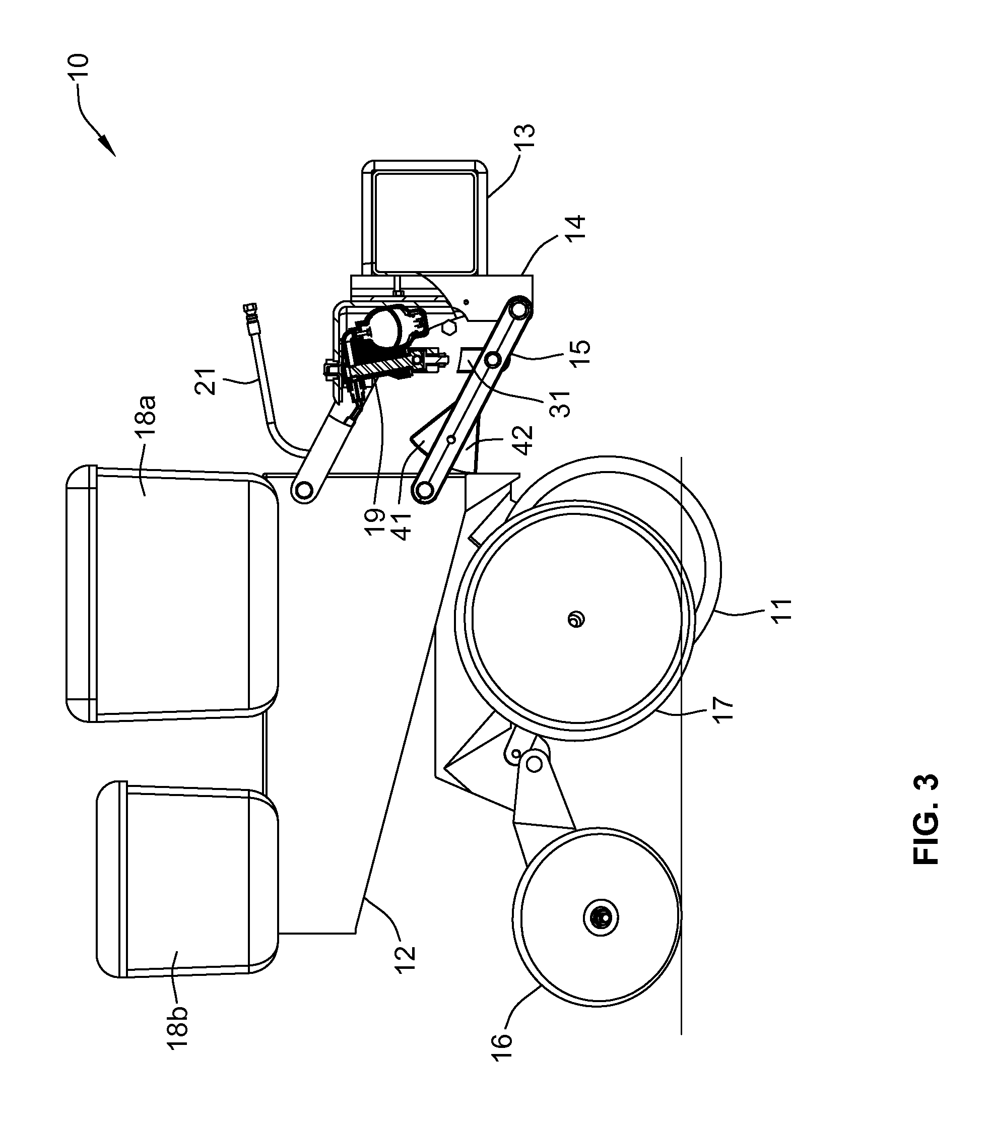
FIG. 3 is the same side elevation shown in FIG. 1 but with the linkage tilted upwardly to move the row unit to a raised position.
FIG. 4 is the same side elevation shown in FIG. 1 but with the linkage tilted downwardly to move the row unit to a lowered position.
FIG. 5 is a top plan view of the hydraulic cylinder and accumulator unit included in the row unit of FIGS. 1-4.
FIG. 6 is a vertical section taken along line 6-6 in FIG. 5.
FIG. 7 is a side elevation of the unit shown in FIGS. 5 and 6 connected to a pair of supporting elements, with the support structures and the connecting portions of the hydraulic cylinder shown in section.
FIGS. 8A and 8B are enlarged cross sectional views of the supporting structures shown in section in FIG. 7.
FIG. 9 is an enlarged perspective of the right-hand end portion of FIG. 1 with a portion of the four-bar linkage broken away to reveal the mounting of the hydraulic cylinder/accumulator unit.
FIG. 10 is a schematic diagram of a first hydraulic control system for use with the row unit of FIGS. 1-9.
FIG. 11 is a schematic diagram of a second hydraulic control system for use with the row unit of FIGS. 1-9.
FIG. 12 is a diagram illustrating one application of the hydraulic control system of FIG. 11.
DETAILED DESCRIPTION OF ILLUSTRATED EMBODIMENTS
Although the invention will be described in connection with certain preferred embodiments, it will be understood that the invention is not limited to those particular embodiments. On the contrary, the invention is intended to cover all alternatives, modifications, and equivalent arrangements as may be included within the spirit and scope of the invention as defined by the appended claims.
Turning now to the drawings, a planting row unit 10 includes a furrow-opening device for the purpose of planting seed or injecting fertilizer into the soil. In the illustrated embodiment, the furrow-opening device is a V-opener 11 formed by a pair of conventional tilted discs depending from the leading end of a row unit frame 12. It will be understood that other furrow-opening devices may be used. A conventional elongated hollow towing frame 13 (typically hitched to a tractor by a draw bar) is rigidly attached to the front frame 14 of a conventional four-bar linkage assembly 15 that is part of the row unit 10. The four-bar (sometimes referred to as "parallel-bar") linkage assembly 15 is a conventional and well known linkage used in agricultural implements to permit the raising and lowering of tools attached thereto.
As the planting row unit 10 is advanced by the tractor, the V-opener 11 penetrates the soil to form a furrow or seed slot. Other portions of the row unit 10 then deposit seed in the seed slot and fertilizer adjacent to the seed slot, and close the seed slot by distributing loosened soil into the seed slot with a pair of closing wheels 16. A gauge wheel 17 determines the planting depth for the seed and the height of introduction of fertilizer, etc. Bins 18a and 18b on the row unit carry the chemicals and seed which are directed into the soil. The planting row unit 10 is urged downwardly against the soil by its own weight, and, in addition, a hydraulic cylinder 19 is coupled between the front frame 14 (also referred to herein as "front bracket") and the linkage assembly 15 to urge the row unit 11 downwardly with a controllable force that can be adjusted for different soil conditions. The hydraulic cylinder 19 may also be used to lift the row unit off the ground for transport by a heavier, stronger, fixed-height frame that is also used to transport large quantities of fertilizer for application via multiple row units.
The hydraulic cylinder 19 is shown in more detail in FIGS. 5 and 6. Pressurized hydraulic fluid from the tractor is supplied by a hose 20 to a port 21 that leads into a matching port 22 of a housing 23 that forms a cavity 24 of a hydraulic cylinder containing a ram 25. The housing 23 also forms a side port 26a that leads into cavity 26b that contains a gas-charged hydraulic accumulator 27. The lower end of the cavity 24 is formed by the top end surface of the ram 25, so that the hydraulic pressure exerted by the hydraulic fluid on the end surface of the ram 25 urges the ram downwardly (as viewed in FIG. 6), with a force determined by the pressure of the hydraulic fluid and the area of the exposed end surface of the ram 25. The hydraulic fluid thus urges the ram 25 in an advancing direction (see FIG. 4).
As can be seen most clearly in FIG. 9, the hydraulic cylinder 19 and the accumulator 27 are mounted as a single unit on the front frame 14, with the lower end of the ram 25 connected to a crossbar 30 that is joined at one end to a vertical link 31. The upper and lower ends of the link 31 are pivotably attached to upper and lower links 15a and 15b, respectively, on one side of the four-bar linkage 15. The other end of the crossbar 30 is angled upwardly and pivotably attached to the upper link 15c on the opposite side of the four-bar linkage 15. With this mounting arrangement, retracting movement of the ram 25 into the cavity 24 tilts the linkage assembly 15 upwardly, as depicted in FIG. 3, thereby raising the row unit. Conversely, advancing movement of the ram 25 tilts the linkage assembly 15 downwardly, as depicted in FIG. 4, thereby lowering the row unit.
The accumulator 27 includes a diaphragm 28 that divides the interior of the accumulator into a hydraulic-fluid chamber 29a and a gas-filled chamber 29b, e.g., filled with pressurized nitrogen. FIG. 2 shows the ram 25 in a position where the diaphragm 28 is not deflected in either direction, indicating that the pressures exerted on opposite sides of the diaphragm are substantially equal. In FIG. 3, the ram 25 has been retracted by upward movement of the row unit, and the diaphragm 28 is deflected downwardly by the hydraulic fluid forced into the accumulator 27 by the retracting movement of the ram 25. In FIG. 4, the ram 25 has been moved to its most advanced position, and the diaphragm 28 is deflected upwardly by the air pressure as hydraulic fluid flows from the accumulator into the cavity 24. The use of this compact hydraulic down-force unit with an integral accumulator on each row unit provides the advantages of quick response and remote adjustability of a hydraulic down-force control system. If an obstruction requires quick movement, oil can flow quickly and freely between the force cylinder and the adjacent accumulator.
As can be seen in FIG. 4, advancing movement of the ram 25 is limited by engagement of stops 41, 42 on the lower links of the four-bar linkage 15, with the row unit frame 12. This prevents any further advancement of the ram 25. Advancing movement of the ram 25 expands the size of the cavity 24 (see FIG. 4), which causes the diaphragm 28 in the accumulator 27 to deflect to the position illustrated in FIG. 4 and reduce the amount of hydraulic fluid in the accumulator 27. When the ram 25 is in this advanced position, the row unit is in its lowermost position.
In FIG. 3, the ram 25 has been withdrawn to its most retracted position, which can occur when the row unit encounters a rock or other obstruction, for example. When the ram 25 is in this retracted position, the row unit is in its uppermost position. As can be seen in FIG. 3, retracting movement of the ram 25 is limited by engagement of stops 41, on the lower links of the four-bar linkage 15, with the row unit frame 12.
Retracting movement of the ram 25 reduces the volume of the cavity 24 (see FIG. 3), which causes a portion of the fixed volume of hydraulic fluid in the cylinder 19 to flow into the chamber 29a of the accumulator 27, causing the diaphragm 28 to deflect to the position illustrated in FIG. 3. This deflection of the diaphragm 28 into the chamber 29b compresses the gas in that chamber. To enter the chamber 29a, the hydraulic fluid must flow through a port 32 in the top of the accumulator 27, which limits the rate at which the hydraulic fluid flows into the accumulator. This controlled rate of flow of the hydraulic fluid has a damping effect on the rate at which the ram 25 retracts or advances, thereby avoiding sudden large movements of the moving parts of the row unit, including the V-opener 11.
When the external obstruction causing the row unit 10 to rise is cleared, the combined effects of the pressurized gas in the accumulator 27 on the diaphragm 28 and the pressure of the hydraulic fluid return the ram 25 to a lower position. This downward force on the V-opener 11 holds it in the soil and prevents uncontrolled bouncing of the V-opener 11 over irregular terrain. The downward force applied to the V-opener 11 can be adjusted by changing the pressure of the hydraulic fluid supplied to the cylinder 19.
As can be seen in FIGS. 5 and 6, the single unitary housing 23 forms both the cavity 26b that contains the accumulator 27 and the cavity 24 of the hydraulic cylinder 19 and the fluid passageway 24 that connects the cavity 24 of the hydraulic cylinder 19 to the cavity 27 of the accumulator. By integrating the hydraulic cylinder 19 and the accumulator 27 in a single housing, there is no relative motion possible between the cylinder 19 and the accumulator 27, with minimal possibility for fluid passageways to act like orifices. The cylinder 19 and the accumulator 27 remain in fixed positions relative to each other regardless of the movements of the planter row unit via the linkage assembly 15. In this way the upward motion of the ram 25 that occurs when the planter row unit rolls over an obstruction is directly converted into compression of the gas in the accumulator 27 without restriction. It also allows the accumulator 27, which is by definition an energy storage device, to be mounted in a fully enclosed and safe housing. The accumulator 27 can be securely mounted to avoid puncture or rapid discharge (if it comes loose), or damage from hitting another part of the implement or a foreign object. The integrated cylinder and accumulator is also a convenient single package for installation and replacement and minimizes the number of hydraulic hoses and adapters (potential leakage points).
FIGS. 7, 8A and 8B illustrate in more detail how the illustrative hydraulic cylinder/accumulator unit is attached to the front frame 14 and the linkage assembly 15. The top of the unitary housing 23 forms a stem 41 that projects upwardly through a hole 51 in a bracket 50 (also referred to herein as "support bracket") attached to the front frame 14. The outer surface of the stem 41 is threaded to receive a nut 52 that connects the housing 23 to the bracket 50. The hole 51 is oversized and a rubber washer 52a is installed on the stem 41 between the nut 52 and the bracket 50 to allow a limited amount of tilting movement of the housing relative to the bracket 50. At the base of the stem 41, beneath the bracket 50, the housing 23 forms a shoulder 42 that engages a curved bearing ring 53 that also engages a mating lower surface of a washer 54. Thus, the housing 23 can be tilted relative to the axis of the hole 51, with the shoulder 42 sliding over the lower surface of the bearing ring 53.
A similar arrangement is provided at the lower end of the ram 25, where a stem 60 extends downwardly through a hole 61 in the crossbar 30 that is pivotably attached to the linkage assembly 15. A nut 62 is threaded onto the stem 60 to connect the ram to the crossbar 30. The hole 61 is oversized and a rubber washer 62a is installed on the stem 60 between the nut 62 and the crossbar 30 to allow a limited amount of tilting movement of the ram 25 relative to the crossbar 30. Above the crossbar 30, a flange 63 on the ram 25 forms a curved conical surface 64 that engages a mating surface of a curved bearing ring 65 that also engages a mating upper surface of a washer 66. Thus, the ram 25 can be tilted relative to the axis of the hole 61, with the flange 63 sliding over the upper surface of the bearing ring 65.
The use of a hydraulic system permits on-the-go adjustments to be made very rapidly because the hydraulic fluid is incompressible and therefore acts more directly than an air system. In addition, hydraulic fluids typically operate at higher pressures, which allows for greater changes in applied forces. The accumulator 27 allows the fluid system to flex and float with the changing terrain and soil conditions. The accumulator 27 is preferably centrally mounted so that when any single row unit moves over an obstruction, the down-pressure cylinder 19 moves to displace the hydraulic fluid along a common set of lines connecting all row units. The gas in the accumulator is compressed at the same time, allowing for isolation among the row units so that upward movement of one row unit does not cause downward movement of other row units. Although the illustrative hydraulic ram is single-acting, it is also possible to use a double-acting ram, or a single-acting ram in combination with a return spring.
Another advantage of the compact hydraulic cylinder/accumulator unit is that it can conveniently mounted to the same brackets that are provided in many row units for mounting an air bag, to control the down pressure on the row unit. For example, in FIG. 9, the brackets 50 and 51 on which the hydraulic cylinder/accumulator is mounted are the brackets that are often connected to an air bag, and thus the same row unit can be used interchangeably with either an air bag or the hydraulic cylinder/accumulator to control the down pressure on the row unit.
FIG. 10 is a schematic of a hydraulic control system for supplying pressurized hydraulic fluid to the cylinders 19 of multiple row units. A source 100 of pressurized hydraulic fluid, typically located on a tractor, supplies hydraulic fluid under pressure to a valve 101 via supply line 102 and receives returned fluid through a return line 103. The valve 101 can be set by an electrical control signal 51 on line 104 to deliver hydraulic fluid to an output line 105 at a desired constant pressure. The output line is connected to a manifold 106 that in turn delivers the pressurized hydraulic fluid to individual feed lines 107 connected to the ports 71 of the respective hydraulic cylinders 19 of the individual row units. With this control system, the valve 101 is turned off, preferably by a manually controlled on/off valve V, after all the cylinders 19 have been filled with pressurized hydraulic fluid, to maintain a fixed volume of fluid in each cylinder.
FIG. 11 is a schematic of a modified hydraulic control system that permits individual control of the supply of hydraulic fluid to the cylinder 19 of each separate row unit via feed lines 107 connected to the ports 71 of the respective cylinders 19. Portions of this system that are common to those of the system of FIG. 10 are identified by the same reference numbers. The difference in this system is that each separate feed line 107 leading to one of the row units is provided with a separate control valve 110 that receives its own separate control signal on a line 111 from a controller 112. This arrangement permits the supply of pressurized hydraulic fluid to each row unit to be turned off and on at different times by the separate valve 110 for each unit, with the times being controlled by the separate control signals supplied to the valves 110 by the controller 112. The individual valves 110 receive pressurized hydraulic fluid via the manifold 106, and return hydraulic fluid to a sump on the tractor via separate return line 113 connected to a return manifold 114 connected back to the hydraulic system 100 of the tractor.
FIG. 12 illustrates on application for the controllable hydraulic control system of FIG. 11. Modern agricultural equipment often includes GPS systems that enable the user to know precisely where a tractor is located in real time. Thus, when a gang of planting row units 120 towed by a tractor 121 begins to cross a headland 122 in which the rows 123 are not orthogonal to the main rows 124 of a field, each planting row unit 120 can be turned off just as it enters the headland 122, to avoid double-planting while the tractor 121 makes a turn through the headland. With the control system of FIG. 11, the hydraulic cylinder 19 of each row unit can also be separately controlled to turn off the supply of pressurized hydraulic fluid at a different time for each row unit, so that each row unit is raised just as it enters the headland, to avoid disrupting the rows already planted in the headland.
One benefit of the system of FIG. 11 is that as agricultural planters, seeders, fertilizer applicators, tillage equipment and the like become wider with more row units on each frame, often 36 30-inch rows or 54 20-inch rows on a single 90-foot wide toolbar, each row unit can float vertically independently of every other row unit. Yet the following row units still have the down force remotely adjustable from the cab of the tractor or other selected location. This permits very efficient operation of a wide planter or other agricultural machine in varying terrain without having to stop to make manual adjustment to a large number of row units, resulting in a reduction in the number of acres planted in a given time period. One of the most important factors in obtaining a maximum crop yield is timely planting. By permitting remote down force adjustment of each row unit (or group of units), including the ability to quickly release all down force and let the row cleaner quickly rise, e.g., when approaching a wet spot in the field, one can significantly increase the planter productivity or acres planted per day, thereby improving yields and reducing costs of production.
On wide planters or other equipment, at times 90 feet wide or more and planting at 6 mph or more forward speeds, one row unit must often rise or fall quickly to clear a rock or plant into an abrupt soil depression. Any resistance to quick movement results in gouging of the soil or an uncleared portion of the field and, thus, reduced yield. With the row unit having its own hydraulic accumulator, the hydraulic cylinder can move quickly and with a nearly constant down force. Oil displaced by or required by quick movement of the ram is quickly moved into or out of the closely mounted accumulator which is an integral part of each row unit. The accumulator diaphragm or piston supplies or accepts fluid as required at a relatively constant pressure and down force as selected manually or automatically by the hydraulic control system. By following the soil profile closely and leaving a more uniform surface, the toolbar-frame-mounted row unit permits the planter row unit following independently behind to use less down force for its function, resulting in more uniform seed depth control and more uniform seedling emergence. More uniform seedling stands usually result in higher yields than less uniform seedling stands produced by planters with less accurate row cleaner ground following.
The term row unit refers to a unit that is attached to a towing frame in a way that permits the unit to move vertically relative to the towing frame and other units attached to that same towing frame. Most row units are equipped to form, plant and close a single seed furrow, but row units are also made to form, plant and close two or more adjacent seed furrows.
It will be evident to those skilled in the art that the invention is not limited to the details of the foregoing illustrated embodiments and that the present invention may be embodied in other specific forms without departing from the spirit or essential attributes thereof. The present embodiments are therefore to be considered in all respects as illustrative and not restrictive, the scope of the invention being indicated by the appended claims rather than by the foregoing description, and all changes which come within the meaning and range of equivalency of the claims are therefore intended to be embraced therein.
* * * * *
References
D00000
D00001
D00002
D00003
D00004
D00005
D00006
D00007
D00008
D00009
XML
uspto.report is an independent third-party trademark research tool that is not affiliated, endorsed, or sponsored by the United States Patent and Trademark Office (USPTO) or any other governmental organization. The information provided by uspto.report is based on publicly available data at the time of writing and is intended for informational purposes only.
While we strive to provide accurate and up-to-date information, we do not guarantee the accuracy, completeness, reliability, or suitability of the information displayed on this site. The use of this site is at your own risk. Any reliance you place on such information is therefore strictly at your own risk.
All official trademark data, including owner information, should be verified by visiting the official USPTO website at www.uspto.gov. This site is not intended to replace professional legal advice and should not be used as a substitute for consulting with a legal professional who is knowledgeable about trademark law.