Magnetic actuators for haptic response
Moussette , et al.
U.S. patent number 10,236,760 [Application Number 15/025,425] was granted by the patent office on 2019-03-19 for magnetic actuators for haptic response. This patent grant is currently assigned to Apple Inc.. The grantee listed for this patent is Apple Inc.. Invention is credited to Patrick Kessler, John B. Morrell, Camille Moussette, Samuel Weiss.


View All Diagrams
| United States Patent | 10,236,760 |
| Moussette , et al. | March 19, 2019 |
Magnetic actuators for haptic response
Abstract
In an embodiment, an actuator or circuit includes elements moveably coupled via bearings positioned between curved grooves. The bearings and the curves may exert a restorative force to return the elements to an original position after movement and may be spherical, cubic, cylindrical, and/or include gears that interact with groove gears. In some embodiments, an electrical coil may be coplanar with a surface of an element and a hard magnet may be positioned in the center and be polarized to stabilize or destabilize the element with respect to another element. In various embodiments, a magnetic circuit includes an element with an electrical coil wrapped in multiple directions around the element. In some embodiments, an actuator includes attraction elements and exertion of force causes an element to approach, contact, and/or magnetically attach to one of the attraction elements.
| Inventors: | Moussette; Camille (Cupertino, CA), Morrell; John B. (Cupertino, CA), Kessler; Patrick (San Francisco, CA), Weiss; Samuel (Los Altos, CA) | ||||||||||
|---|---|---|---|---|---|---|---|---|---|---|---|
| Applicant: |
|
||||||||||
| Assignee: | Apple Inc. (Cupertino,
CA) |
||||||||||
| Family ID: | 49510493 | ||||||||||
| Appl. No.: | 15/025,425 | ||||||||||
| Filed: | September 30, 2013 | ||||||||||
| PCT Filed: | September 30, 2013 | ||||||||||
| PCT No.: | PCT/US2013/062556 | ||||||||||
| 371(c)(1),(2),(4) Date: | March 28, 2016 | ||||||||||
| PCT Pub. No.: | WO2015/047372 | ||||||||||
| PCT Pub. Date: | April 02, 2015 |
Prior Publication Data
| Document Identifier | Publication Date | |
|---|---|---|
| US 20160211736 A1 | Jul 21, 2016 | |
| Current U.S. Class: | 1/1 |
| Current CPC Class: | G06F 3/016 (20130101); G06F 3/01 (20130101); H02K 7/108 (20130101); H02K 1/34 (20130101); H02K 7/08 (20130101); H02K 33/16 (20130101) |
| Current International Class: | G06F 3/01 (20060101); H02K 7/108 (20060101); H02K 33/16 (20060101); H02K 1/34 (20060101) |
| Field of Search: | ;340/407.1,407.2 |
References Cited [Referenced By]
U.S. Patent Documents
| 3001049 | September 1961 | Didier |
| 3390287 | June 1968 | Sonderegger |
| 3419739 | December 1968 | Clements |
| 4236132 | November 1980 | Zissimopoulos |
| 4412148 | October 1983 | Klicker et al. |
| 4414984 | November 1983 | Zarudiansky |
| 4695813 | September 1987 | Nobutoki et al. |
| 4975616 | December 1990 | Park |
| 5010772 | April 1991 | Bourland |
| 5245734 | September 1993 | Issartel |
| 5283408 | February 1994 | Chen |
| 5293161 | March 1994 | MacDonald et al. |
| 5317221 | May 1994 | Kubo et al. |
| 5365140 | November 1994 | Ohya et al. |
| 5434549 | July 1995 | Hirabayashi et al. |
| 5436622 | July 1995 | Gutman et al. |
| 5510584 | April 1996 | Norris |
| 5510783 | April 1996 | Findlater et al. |
| 5513100 | April 1996 | Parker et al. |
| 5587875 | December 1996 | Sellers |
| 5590020 | December 1996 | Sellers |
| 5602715 | February 1997 | Lempicki et al. |
| 5619005 | April 1997 | Shibukawa et al. |
| 5621610 | April 1997 | Moore et al. |
| 5625532 | April 1997 | Sellers |
| 5629578 | May 1997 | Winzer et al. |
| 5635928 | June 1997 | Takagi et al. |
| 5718418 | February 1998 | Gugsch |
| 5739759 | April 1998 | Nakazawa et al. |
| 5742242 | April 1998 | Sellers |
| 5783765 | July 1998 | Muramatsu |
| 5793605 | August 1998 | Sellers |
| 5812116 | September 1998 | Malhi |
| 5813142 | September 1998 | Demon |
| 5818149 | October 1998 | Safari et al. |
| 5896076 | April 1999 | Van Namen |
| 5907199 | May 1999 | Miller |
| 5951908 | September 1999 | Cui et al. |
| 5959613 | September 1999 | Rosenberg et al. |
| 5973441 | October 1999 | Lo et al. |
| 5982304 | November 1999 | Selker et al. |
| 5982612 | November 1999 | Roylance |
| 5995026 | November 1999 | Sellers |
| 5999084 | December 1999 | Armstrong |
| 6069433 | May 2000 | Lazarus et al. |
| 6078308 | June 2000 | Rosenberg et al. |
| 6127756 | October 2000 | Iwaki |
| 6135886 | October 2000 | Armstrong |
| 6218966 | April 2001 | Goodwin |
| 6220550 | April 2001 | McKillip, Jr. |
| 6222525 | April 2001 | Armstrong |
| 6252336 | June 2001 | Hall |
| 6342880 | January 2002 | Rosenberg et al. |
| 6351205 | February 2002 | Armstrong |
| 6373465 | April 2002 | Jolly et al. |
| 6408187 | June 2002 | Merriam |
| 6411276 | June 2002 | Braun et al. |
| 6429849 | August 2002 | An |
| 6438393 | August 2002 | Surronen |
| 6444928 | September 2002 | Okamoto et al. |
| 6455973 | September 2002 | Ineson |
| 6465921 | October 2002 | Horng |
| 6552404 | April 2003 | Hynes |
| 6552471 | April 2003 | Chandran et al. |
| 6557072 | April 2003 | Osborn |
| 6642857 | November 2003 | Schediwy |
| 6693626 | February 2004 | Rosenberg |
| 6717573 | April 2004 | Shahoian et al. |
| 6809462 | October 2004 | Pelrine et al. |
| 6809727 | October 2004 | Piot et al. |
| 6864877 | March 2005 | Braun et al. |
| 6906697 | June 2005 | Rosenberg |
| 6906700 | June 2005 | Armstrong |
| 6906703 | June 2005 | Vablais et al. |
| 6952203 | October 2005 | Banerjee et al. |
| 6954657 | October 2005 | Bork et al. |
| 6963762 | November 2005 | Kaaresoja et al. |
| 6995752 | February 2006 | Lu |
| 7005811 | February 2006 | Wakuda et al. |
| 7016707 | March 2006 | Fujisawa et al. |
| 7022927 | April 2006 | Hsu |
| 7023112 | April 2006 | Miyamoto et al. |
| 7081701 | July 2006 | Yoon et al. |
| 7091948 | August 2006 | Chang et al. |
| 7121147 | October 2006 | Okada |
| 7123948 | October 2006 | Nielsen |
| 7130664 | October 2006 | Williams |
| 7136045 | November 2006 | Rosenberg et al. |
| 7161580 | January 2007 | Bailey et al. |
| 7162928 | January 2007 | Shank et al. |
| 7170498 | January 2007 | Huang |
| 7176906 | February 2007 | Williams et al. |
| 7180500 | February 2007 | Marvit et al. |
| 7182691 | February 2007 | Schena |
| 7194645 | March 2007 | Bieswanger et al. |
| 7217891 | May 2007 | Fischer et al. |
| 7218310 | May 2007 | Tierling et al. |
| 7219561 | May 2007 | Okada |
| 7253350 | August 2007 | Noro et al. |
| 7269484 | September 2007 | Hein |
| 7333604 | February 2008 | Zernovizky et al. |
| 7334350 | February 2008 | Ellis |
| 7348968 | March 2008 | Dawson |
| 7388741 | June 2008 | Konuma et al. |
| 7392066 | June 2008 | Hapamas |
| 7423631 | September 2008 | Shahoian et al. |
| 7446752 | November 2008 | Goldenberg et al. |
| 7469155 | December 2008 | Chu |
| 7469595 | December 2008 | Kessler et al. |
| 7471033 | December 2008 | Thiesen et al. |
| 7495358 | February 2009 | Kobayashi et al. |
| 7508382 | March 2009 | Denoue et al. |
| 7561142 | July 2009 | Shahoian et al. |
| 7562468 | July 2009 | Ellis |
| 7569086 | August 2009 | Chandran |
| 7575368 | August 2009 | Guillaume |
| 7586220 | September 2009 | Roberts |
| 7619498 | November 2009 | Miura |
| 7639232 | December 2009 | Grant et al. |
| 7641618 | January 2010 | Noda et al. |
| 7649305 | January 2010 | Priya et al. |
| 7675253 | March 2010 | Dorel |
| 7675414 | March 2010 | Ray |
| 7679611 | March 2010 | Schena |
| 7707742 | May 2010 | Ellis |
| 7710399 | May 2010 | Bruneau et al. |
| 7732951 | June 2010 | Mukaide |
| 7737828 | June 2010 | Yang et al. |
| 7742036 | June 2010 | Grant et al. |
| 7788032 | August 2010 | Moloney |
| 7793429 | September 2010 | Ellis |
| 7793430 | September 2010 | Ellis |
| 7798982 | September 2010 | Zets et al. |
| 7868489 | January 2011 | Amemiya et al. |
| 7886621 | February 2011 | Smith et al. |
| 7888892 | February 2011 | McReynolds et al. |
| 7893922 | February 2011 | Klinghult et al. |
| 7919945 | April 2011 | Houston et al. |
| 7929382 | April 2011 | Yamazaki |
| 7946483 | May 2011 | Miller et al. |
| 7952261 | May 2011 | Lipton et al. |
| 7952566 | May 2011 | Poupyrev et al. |
| 7956770 | June 2011 | Klinghult et al. |
| 7961909 | June 2011 | Mandella et al. |
| 8031172 | October 2011 | Kruse et al. |
| 8044940 | October 2011 | Narusawa |
| 8069881 | December 2011 | Cunha |
| 8077145 | December 2011 | Rosenberg et al. |
| 8081156 | December 2011 | Ruettiger |
| 8082640 | December 2011 | Takeda |
| 8098234 | January 2012 | Lacroix et al. |
| 8123660 | February 2012 | Kruse et al. |
| 8125453 | February 2012 | Shahoian et al. |
| 8141276 | March 2012 | Ellis |
| 8156809 | April 2012 | Tierling et al. |
| 8169401 | May 2012 | Hardwick |
| 8174372 | May 2012 | da Costa |
| 8179202 | May 2012 | Cruz-Hernandez et al. |
| 8188623 | May 2012 | Park et al. |
| 8205356 | June 2012 | Ellis |
| 8210942 | July 2012 | Shimabukuro et al. |
| 8232494 | July 2012 | Purcocks |
| 8242641 | August 2012 | Bae |
| 8248277 | August 2012 | Peterson et al. |
| 8248278 | August 2012 | Schlosser et al. |
| 8253686 | August 2012 | Kyung et al. |
| 8255004 | August 2012 | Huang et al. |
| 8261468 | September 2012 | Ellis |
| 8264465 | September 2012 | Grant et al. |
| 8288899 | October 2012 | Park et al. |
| 8291614 | October 2012 | Ellis |
| 8294600 | October 2012 | Peterson et al. |
| 8315746 | November 2012 | Cox et al. |
| 8344834 | January 2013 | Niiyama |
| 8378797 | February 2013 | Pance et al. |
| 8378798 | February 2013 | Bells et al. |
| 8378965 | February 2013 | Gregorio et al. |
| 8384316 | February 2013 | Houston et al. |
| 8384679 | February 2013 | Paleczny et al. |
| 8390594 | March 2013 | Modarres et al. |
| 8395587 | March 2013 | Cauwels et al. |
| 8398570 | March 2013 | Mortimer et al. |
| 8411058 | April 2013 | Wong et al. |
| 8446264 | May 2013 | Tanase |
| 8451255 | May 2013 | Weber et al. |
| 8461951 | June 2013 | Gassmann et al. |
| 8466889 | June 2013 | Tong et al. |
| 8471690 | June 2013 | Hennig et al. |
| 8487759 | July 2013 | Hill |
| 8515398 | August 2013 | Song et al. |
| 8542134 | September 2013 | Peterson et al. |
| 8545322 | October 2013 | George et al. |
| 8547341 | October 2013 | Takashima et al. |
| 8552859 | October 2013 | Pakula et al. |
| 8570291 | October 2013 | Motomura |
| 8575794 | November 2013 | Lee et al. |
| 8587955 | November 2013 | DiFonzo et al. |
| 8596755 | December 2013 | Hibi |
| 8598893 | December 2013 | Camus |
| 8599047 | December 2013 | Schlosser et al. |
| 8599152 | December 2013 | Wurtenberger et al. |
| 8600354 | December 2013 | Esaki |
| 8614431 | December 2013 | Huppi et al. |
| 8621348 | December 2013 | Ramsay et al. |
| 8629843 | January 2014 | Steeves et al. |
| 8633916 | January 2014 | Bernstein et al. |
| 8674941 | March 2014 | Casparian et al. |
| 8680723 | March 2014 | Subramanian |
| 8682396 | March 2014 | Yang et al. |
| 8686952 | April 2014 | Pope et al. |
| 8710966 | April 2014 | Hill |
| 8723813 | May 2014 | Park et al. |
| 8735755 | May 2014 | Peterson et al. |
| 8760273 | June 2014 | Casparian et al. |
| 8780060 | July 2014 | Maschmeyer et al. |
| 8787006 | July 2014 | Golko et al. |
| 8797152 | August 2014 | Henderson et al. |
| 8798534 | August 2014 | Rodriguez et al. |
| 8803842 | August 2014 | Wakasugi et al. |
| 8836502 | September 2014 | Culbert et al. |
| 8845071 | September 2014 | Yamamoto et al. |
| 8857248 | October 2014 | Shih et al. |
| 8860562 | October 2014 | Hill |
| 8861776 | October 2014 | Lastrucci |
| 8866600 | October 2014 | Yang et al. |
| 8890668 | November 2014 | Pance et al. |
| 8918215 | December 2014 | Bosscher et al. |
| 8928621 | January 2015 | Ciesla et al. |
| 8948821 | February 2015 | Newham et al. |
| 8952937 | February 2015 | Shih et al. |
| 8970534 | March 2015 | Adachi et al. |
| 8976141 | March 2015 | Myers et al. |
| 9008730 | April 2015 | Kim et al. |
| 9012795 | April 2015 | Niu |
| 9013426 | April 2015 | Cole et al. |
| 9019088 | April 2015 | Zawacki et al. |
| 9035887 | May 2015 | Prud'Hommeaux et al. |
| 9072576 | July 2015 | Nishiura |
| 9083821 | July 2015 | Hughes |
| 9092129 | July 2015 | Abdo et al. |
| 9098991 | August 2015 | Park et al. |
| 9117347 | August 2015 | Matthews |
| 9122325 | September 2015 | Peshkin et al. |
| 9131039 | September 2015 | Behles |
| 9134834 | September 2015 | Reshef |
| 9158379 | October 2015 | Cruz-Hernandez et al. |
| 9178509 | November 2015 | Bernstein |
| 9189932 | November 2015 | Kerdemelidis et al. |
| 9201458 | December 2015 | Hunt et al. |
| 9202355 | December 2015 | Hill |
| 9235267 | January 2016 | Pope et al. |
| 9274601 | March 2016 | Faubert et al. |
| 9274602 | March 2016 | Garg et al. |
| 9274603 | March 2016 | Modarres et al. |
| 9275815 | March 2016 | Hoffmann |
| 9293054 | March 2016 | Bruni et al. |
| 9300181 | March 2016 | Maeda et al. |
| 9310906 | April 2016 | Yumiki et al. |
| 9317116 | April 2016 | Ullrich et al. |
| 9317118 | April 2016 | Puskarich |
| 9317154 | April 2016 | Perlin et al. |
| 9318942 | April 2016 | Sugita et al. |
| 9325230 | April 2016 | Yamada et al. |
| 9357052 | May 2016 | Ullrich |
| 9360944 | June 2016 | Pinault |
| 9390599 | July 2016 | Weinberg |
| 9396434 | July 2016 | Rothkopf |
| 9405369 | August 2016 | Modarres et al. |
| 9411423 | August 2016 | Heubel |
| 9417695 | August 2016 | Griffin et al. |
| 9449476 | September 2016 | Lynn |
| 9477342 | October 2016 | Daverman et al. |
| 9501912 | November 2016 | Havskjold et al. |
| 9594450 | July 2017 | Lynn et al. |
| 9778743 | October 2017 | Grant et al. |
| 9779592 | October 2017 | Hoen |
| 9934661 | April 2018 | Hill |
| 9990099 | June 2018 | Ham et al. |
| 2003/0210259 | November 2003 | Liu |
| 2004/0021663 | February 2004 | Suzuki et al. |
| 2004/0127198 | July 2004 | Roskind et al. |
| 2005/0057528 | March 2005 | Kleen |
| 2005/0107129 | May 2005 | Kaewell et al. |
| 2005/0110778 | May 2005 | Ben Ayed |
| 2005/0118922 | June 2005 | Endo |
| 2005/0217142 | October 2005 | Ellis |
| 2005/0237306 | October 2005 | Klein et al. |
| 2005/0248549 | November 2005 | Dietz et al. |
| 2005/0258715 | November 2005 | Schlabach |
| 2006/0014569 | January 2006 | DelGiorno |
| 2006/0154674 | July 2006 | Landschaft et al. |
| 2006/0209037 | September 2006 | Wang et al. |
| 2006/0221052 | October 2006 | Harada et al. |
| 2006/0239746 | October 2006 | Grant |
| 2006/0252463 | November 2006 | Liao |
| 2007/0099574 | May 2007 | Wang |
| 2007/0152974 | July 2007 | Kim et al. |
| 2007/0178942 | August 2007 | Sadler et al. |
| 2007/0188450 | August 2007 | Hernandez et al. |
| 2008/0084384 | April 2008 | Gregorio et al. |
| 2008/0158149 | July 2008 | Levin |
| 2008/0165148 | July 2008 | Williamson |
| 2008/0181501 | July 2008 | Faraboschi |
| 2008/0181706 | July 2008 | Jackson |
| 2008/0192014 | August 2008 | Kent et al. |
| 2008/0204428 | August 2008 | Pierce et al. |
| 2008/0255794 | October 2008 | Levine |
| 2008/0297328 | December 2008 | Crawford |
| 2009/0002328 | January 2009 | Ullrich et al. |
| 2009/0115734 | May 2009 | Fredriksson et al. |
| 2009/0120105 | May 2009 | Ramsay et al. |
| 2009/0128503 | May 2009 | Grant et al. |
| 2009/0135142 | May 2009 | Fu et al. |
| 2009/0167702 | July 2009 | Nurmi |
| 2009/0167704 | July 2009 | Terlizzi et al. |
| 2009/0201608 | August 2009 | Argumedo et al. |
| 2009/0218148 | September 2009 | Hugeback et al. |
| 2009/0225046 | September 2009 | Kim et al. |
| 2009/0236210 | September 2009 | Clark et al. |
| 2009/0267892 | October 2009 | Faubert |
| 2009/0313542 | December 2009 | Cruz-Hernandez et al. |
| 2010/0020036 | January 2010 | Hui et al. |
| 2010/0053087 | March 2010 | Dai et al. |
| 2010/0079264 | April 2010 | Hoellwarth |
| 2010/0089735 | April 2010 | Takeda et al. |
| 2010/0141408 | June 2010 | Doy et al. |
| 2010/0141606 | June 2010 | Bae et al. |
| 2010/0148944 | June 2010 | Kim et al. |
| 2010/0152620 | June 2010 | Ramsay et al. |
| 2010/0164894 | July 2010 | Kim et al. |
| 2010/0188422 | July 2010 | Shingai et al. |
| 2010/0194547 | August 2010 | Terrell et al. |
| 2010/0231508 | September 2010 | Cruz-Hernandez et al. |
| 2010/0231550 | September 2010 | Cruz-Hernandez et al. |
| 2010/0265197 | October 2010 | Purdy |
| 2010/0309141 | December 2010 | Cruz-Hernandez et al. |
| 2010/0328229 | December 2010 | Weber et al. |
| 2011/0053577 | March 2011 | Lee et al. |
| 2011/0107958 | May 2011 | Pance et al. |
| 2011/0121765 | May 2011 | Anderson et al. |
| 2011/0128239 | June 2011 | Polyakov et al. |
| 2011/0148608 | June 2011 | Grant et al. |
| 2011/0157052 | June 2011 | Lee et al. |
| 2011/0163985 | July 2011 | Bae et al. |
| 2011/0193824 | August 2011 | Modarres et al. |
| 2011/0248948 | October 2011 | Griffin et al. |
| 2011/0260988 | October 2011 | Colgate et al. |
| 2011/0263200 | October 2011 | Thornton et al. |
| 2011/0291950 | December 2011 | Tong |
| 2011/0304559 | December 2011 | Pasquero |
| 2012/0068957 | March 2012 | Puskarich et al. |
| 2012/0075198 | March 2012 | Sulem et al. |
| 2012/0092263 | April 2012 | Peterson et al. |
| 2012/0126959 | May 2012 | Zarrabi et al. |
| 2012/0127088 | May 2012 | Pance et al. |
| 2012/0133494 | May 2012 | Cruz-Hernandez et al. |
| 2012/0139844 | June 2012 | Ramstein et al. |
| 2012/0206248 | August 2012 | Biggs |
| 2012/0256848 | October 2012 | Madabusi Srinivasan |
| 2012/0268412 | October 2012 | Cruz-Hernandez et al. |
| 2012/0274578 | November 2012 | Snow et al. |
| 2012/0280927 | November 2012 | Ludwig |
| 2012/0319987 | December 2012 | Woo |
| 2012/0327006 | December 2012 | Lsrar et al. |
| 2013/0027345 | January 2013 | Binzel |
| 2013/0033967 | February 2013 | Chuang et al. |
| 2013/0063285 | March 2013 | Elias |
| 2013/0063356 | March 2013 | Martisauskas |
| 2013/0106699 | May 2013 | Babatunde |
| 2013/0141365 | June 2013 | Lynn et al. |
| 2013/0191741 | July 2013 | Dickinson et al. |
| 2013/0200732 | August 2013 | Jun et al. |
| 2013/0207793 | August 2013 | Weaber et al. |
| 2013/0217491 | August 2013 | Hilbert et al. |
| 2013/0222280 | August 2013 | Sheynblat et al. |
| 2013/0228023 | September 2013 | Drasnin et al. |
| 2013/0261811 | October 2013 | Yagi et al. |
| 2013/0300590 | November 2013 | Dietz et al. |
| 2014/0035397 | February 2014 | Endo et al. |
| 2014/0082490 | March 2014 | Jung et al. |
| 2014/0085065 | March 2014 | Biggs et al. |
| 2014/0143785 | May 2014 | Mistry et al. |
| 2014/0197936 | July 2014 | Biggs et al. |
| 2014/0232534 | August 2014 | Birnbaum et al. |
| 2014/0247227 | September 2014 | Jiang et al. |
| 2014/0267076 | September 2014 | Birnbaum et al. |
| 2014/0267952 | September 2014 | Sirois |
| 2015/0005039 | January 2015 | Liu et al. |
| 2015/0040005 | February 2015 | Faaborg |
| 2015/0090572 | April 2015 | Lee et al. |
| 2015/0169059 | June 2015 | Behles et al. |
| 2015/0192414 | July 2015 | Das et al. |
| 2015/0194165 | July 2015 | Faaborg et al. |
| 2015/0220199 | August 2015 | Wang et al. |
| 2015/0227204 | August 2015 | Gipson et al. |
| 2015/0296480 | October 2015 | Kinsey et al. |
| 2015/0324049 | November 2015 | Kies et al. |
| 2015/0349619 | December 2015 | Degner et al. |
| 2016/0049265 | February 2016 | Bernstein |
| 2016/0063826 | March 2016 | Morrell et al. |
| 2016/0071384 | March 2016 | Hill |
| 2016/0162025 | June 2016 | Shah |
| 2016/0163165 | June 2016 | Morrell et al. |
| 2016/0172953 | June 2016 | Hamel et al. |
| 2016/0195929 | July 2016 | Martinez et al. |
| 2016/0196935 | July 2016 | Bernstein |
| 2016/0206921 | July 2016 | Szabados et al. |
| 2016/0216764 | July 2016 | Morrell et al. |
| 2016/0216766 | July 2016 | Puskarich |
| 2016/0231815 | August 2016 | Moussette et al. |
| 2016/0233012 | August 2016 | Lubinski et al. |
| 2016/0241119 | August 2016 | Keeler |
| 2016/0259480 | September 2016 | Augenbergs et al. |
| 2016/0306423 | October 2016 | Uttermann et al. |
| 2016/0371942 | December 2016 | Smith, IV et al. |
| 2017/0038905 | February 2017 | Bijamov |
| 2017/0070131 | March 2017 | Degner |
| 2017/0084138 | March 2017 | Hajati |
| 2017/0085163 | March 2017 | Hajati |
| 2017/0192507 | July 2017 | Lee et al. |
| 2017/0192508 | July 2017 | Lim et al. |
| 2017/0255295 | September 2017 | Tanemura et al. |
| 2017/0257844 | September 2017 | Miller |
| 2017/0285747 | October 2017 | Chen |
| 2017/0311282 | October 2017 | Miller et al. |
| 2017/0357325 | December 2017 | Yang |
| 2017/0364158 | December 2017 | Wen |
| 2018/0052550 | February 2018 | Zhang et al. |
| 2018/0075715 | March 2018 | Morrell |
| 2018/0081441 | March 2018 | Pedder |
| 2018/0203513 | July 2018 | Rihn |
| 2015100710 | Jul 2015 | AU | |||
| 2016100399 | May 2016 | AU | |||
| 2355434 | Feb 2002 | CA | |||
| 1324030 | Nov 2001 | CN | |||
| 1817321 | Aug 2006 | CN | |||
| 101120290 | Feb 2008 | CN | |||
| 101409164 | Apr 2009 | CN | |||
| 101763192 | Jun 2010 | CN | |||
| 101903848 | Dec 2010 | CN | |||
| 101938207 | Jan 2011 | CN | |||
| 102025257 | Apr 2011 | CN | |||
| 201829004 | May 2011 | CN | |||
| 102163076 | Aug 2011 | CN | |||
| 102246122 | Nov 2011 | CN | |||
| 102315747 | Jan 2012 | CN | |||
| 102591512 | Jul 2012 | CN | |||
| 102667681 | Sep 2012 | CN | |||
| 102713805 | Oct 2012 | CN | |||
| 102768593 | Nov 2012 | CN | |||
| 102844972 | Dec 2012 | CN | |||
| 102915111 | Feb 2013 | CN | |||
| 103019569 | Apr 2013 | CN | |||
| 103154867 | Jun 2013 | CN | |||
| 103181090 | Jun 2013 | CN | |||
| 103218104 | Jul 2013 | CN | |||
| 103278173 | Sep 2013 | CN | |||
| 103416043 | Nov 2013 | CN | |||
| 103440076 | Dec 2013 | CN | |||
| 103970339 | Aug 2014 | CN | |||
| 104220963 | Dec 2014 | CN | |||
| 104956244 | Sep 2015 | CN | |||
| 105556268 | May 2016 | CN | |||
| 19517630 | Nov 1996 | DE | |||
| 10330024 | Jan 2005 | DE | |||
| 102009038103 | Feb 2011 | DE | |||
| 102011115762 | Apr 2013 | DE | |||
| 0483955 | May 1992 | EP | |||
| 1047258 | Oct 2000 | EP | |||
| 1686776 | Aug 2006 | EP | |||
| 2060967 | May 2009 | EP | |||
| 2073099 | Jun 2009 | EP | |||
| 2194444 | Jun 2010 | EP | |||
| 2264562 | Dec 2010 | EP | |||
| 2315186 | Apr 2011 | EP | |||
| 2374430 | Oct 2011 | EP | |||
| 2395414 | Dec 2011 | EP | |||
| 2461228 | Jun 2012 | EP | |||
| 2631746 | Aug 2013 | EP | |||
| 2434555 | Oct 2013 | EP | |||
| H05301342 | Nov 1993 | JP | |||
| 2002199689 | Jul 2002 | JP | |||
| 2002102799 | Sep 2002 | JP | |||
| 200362525 | Mar 2003 | JP | |||
| 2004236202 | Aug 2004 | JP | |||
| 2010272903 | Dec 2010 | JP | |||
| 2014235133 | Dec 2014 | JP | |||
| 2016095552 | May 2016 | JP | |||
| 20050033909 | Apr 2005 | KR | |||
| 1020100046602 | May 2010 | KR | |||
| 1020110101516 | Sep 2011 | KR | |||
| 20130024420 | Mar 2013 | KR | |||
| 200518000 | Nov 2007 | TW | |||
| 200951944 | Dec 2009 | TW | |||
| 201145336 | Dec 2011 | TW | |||
| 201218039 | May 2012 | TW | |||
| 201425180 | Jul 2014 | TW | |||
| WO 97/16932 | May 1997 | WO | |||
| WO 01/059588 | Aug 2001 | WO | |||
| WO 02/073587 | Sep 2002 | WO | |||
| WO 03/038800 | May 2003 | WO | |||
| WO 06/057770 | Jun 2006 | WO | |||
| WO 07/114631 | Oct 2007 | WO | |||
| WO 08/075082 | Jun 2008 | WO | |||
| WO 09/038862 | Mar 2009 | WO | |||
| WO 09/068986 | Jun 2009 | WO | |||
| WO 09/097866 | Aug 2009 | WO | |||
| WO 09/122331 | Oct 2009 | WO | |||
| WO 09/150287 | Dec 2009 | WO | |||
| WO 10/085575 | Jul 2010 | WO | |||
| WO 10/087925 | Aug 2010 | WO | |||
| WO 11/007263 | Jan 2011 | WO | |||
| WO 12/052635 | Apr 2012 | WO | |||
| WO 12/129247 | Sep 2012 | WO | |||
| WO 13/069148 | May 2013 | WO | |||
| WO 13/169302 | Nov 2013 | WO | |||
| WO 14/018086 | Jan 2014 | WO | |||
| WO 13/169299 | Nov 2014 | WO | |||
| WO 15/023670 | Feb 2015 | WO | |||
Other References
|
US. Appl. No. 15/800,630, filed Nov. 1, 2017, Morrell et al. cited by applicant . U.S. Appl. No. 15/881,476, filed Jan. 26, 2018, Moussette et al. cited by applicant . Astronomer's Toolbox, "The Electromagnetic Spectrum," http://imagine.gsfc.nasa.gov/science/toolbox/emspectrum1.html, updated Mar. 2013, 4 pages. cited by applicant . Hasser et al., "Preliminary Evaluation of a Shape-Memory Alloy Tactile Feedback Display," Advances in Robotics, Mechantronics, and Haptic Interfaces, ASME, DSC-vol. 49, pp. 73-80, 1993. cited by applicant . Hill et al., "Real-time Estimation of Human Impedance for Haptic Interfaces," Stanford Telerobotics Laboratory, Department of Mechanical Engineering, Stanford University, Third Joint Eurohaptics Conference and Symposium on Haptic Interfaces for Virtual Environment and Teleoperator Systems, Salt Lake City, Utah, Mar. 18-20, 2009, pp. 440-445. cited by applicant . Kim et al., "Tactile Rendering of 3D Features on Touch Surfaces," UIST '13, Oct. 8-11, 2013, St. Andrews, United Kingdom, 8 pages. cited by applicant . Lee et al, "Haptic Pen: Tactile Feedback Stylus for Touch Screens," Mitsubishi Electric Research Laboratories, http://wwwlmerl.com, 6 pages, Oct. 2004. cited by applicant . Invitation to Pay Additional Fees dated Apr. 9, 2014, PCT/US2013/062556, 7 pages. cited by applicant . International Search Report and Written Opinion dated Jun. 18, 2014, PCT/US2013/062556, 16 pages. cited by applicant . U.S. Appl. No. 15/583,938, filed May 1, 2017 Hill. cited by applicant . U.S. Appl. No. 15/621,966, filed Jun. 13, 2017, Pedder et al. cited by applicant . U.S. Appl. No. 15/621,930, filed Jun. 13, 2017, Wen et al. cited by applicant . U.S. Appl. No. 15/622,017, filed Jun. 13, 2017, Yang et al. cited by applicant . U.S. Appl. No. 15/641,192, filed Jul. 3, 2017, Miller et al. cited by applicant . Nakamura, "A Torso Haptic Display Based on Shape Memory Alloy Actuators," Massachusetts Institute of Technology, 2003, pp. 1-123. cited by applicant . U.S. Appl. No. 15/251,459,filed Aug. 30, 2016, Miller et al. cited by applicant . U.S. Appl. No. 15/260,047, filed Sep. 8, 2016, Degner. cited by applicant . U.S. Appl. No. 15/306,034, filed Oct. 21, 2016, Bijamov et al. cited by applicant . U.S. Appl. No. 15/364,822, filed Nov. 30, 2016, Chen. cited by applicant . U.S. Appl. No. 15/897,968, filed Feb. 15, 2018, Hill. cited by applicant. |
Primary Examiner: Swarthout; Brent
Attorney, Agent or Firm: Brownstein Hyatt Farber Schreck, LLP
Claims
We claim:
1. An actuator, comprising: a fixed body element, including at least one first groove and at least one electrical coil; a moveable body element, including at least one second groove and a first and second hard magnet; and at least one bearing positioned between the at least one first groove and the at least one second groove that separates the fixed body element from the moveable body element; wherein the moveable body element is magnetically attracted toward the fixed body element, the first hard magnet has an opposite polarity facing a surface of the moveable body element than the second hard magnet, and at least one of the at least one first groove or the at least one second groove is curved such that applying a lateral force to the moveable body element causes the at least one bearing to force the moveable body element vertically away from the fixed body element.
2. The actuator of claim 1, wherein ceasing to apply the lateral force causes the at least one bearing to allow the moveable body element to move closer to the fixed body element.
3. The actuator of claim 1, wherein the at least one bearing is cylindrical.
4. The actuator of claim 1, wherein the moveable body element further includes at least one soft magnet positioned such that the first and second hard magnets are positioned between the at least one soft magnet and the fixed body element.
5. The actuator of claim 1, wherein the at least one bearing comprises a plurality of bearings, the at least one first groove comprises a plurality of first grooves, the at least one second groove comprises a plurality of second grooves, and each of the plurality of bearings is positioned between one of the plurality of first grooves and one of the plurality of second grooves.
6. An actuator, comprising: a first body element comprising a first hard magnet and a second hard magnet; and a second body element that is moveably coupled to the first body element and comprises at least one electrical coil and at least one center hard magnet positioned in a center of the at least one electrical coil; wherein the center hard magnet is polarized to either: oppose a direction of a magnetic flux; or correspond with the direction of the magnetic flux.
7. The actuator of claim 6, wherein the center hard magnet is polarized to correspond with the direction of the magnetic flux and exerts a restorative force to return the second body element to an original position with respect to the first body element after lateral movement.
8. The actuator of claim 7, wherein the center hard magnet is polarized to oppose the direction of the magnetic flux and resists return of the second body element to the original position.
9. The actuator of claim 6, wherein the center hard magnet is polarized to oppose the direction of the magnetic flux and destabilizes centering of the second body element with respect to the first body element.
10. The actuator of claim 6, wherein the first body element further comprises at least a first soft magnet element, and wherein at least one of the first hard magnet or the second hard magnet is positioned between the first soft magnet element and the second body element.
11. The actuator of claim 6, wherein the second body element further comprises at least a second soft magnet element, and wherein at least one of the at least one electrical coil or the at least one center hard magnet is positioned between the second soft magnet element and the first body element.
12. A magnetic circuit, comprising: a moveable bar element that includes at least a first hard magnet and a second hard magnet; and a fixed bar element that includes an electrical coil structure wound around the fixed bar element, wherein a first section of the electrical coil structure is wound in a first direction around a first area of the fixed bar element, and a second section of the electrical coil structure is wound in a second direction around a second area of the fixed bar element; wherein the moveable bar element is moveably coupled to the fixed bar element.
13. The magnetic circuit of claim 12, wherein the first direction and the second direction are opposing directions.
14. The magnetic circuit of claim 12, wherein the electrical coil structure includes a middle section where the direction of winding is changed between the first direction and the second direction.
15. The magnetic circuit of claim 14, wherein the middle section is attached to the fixed bar element.
16. The magnetic circuit of claim 12, wherein the moveable bar element further comprises at least one soft magnet wherein at least one of the first hard magnet or the second hard magnet is positioned between the at least one soft magnet and the fixed bar element.
17. The magnetic circuit of claim 12, wherein the moveable bar element is moveably coupled to the fixed bar element by at least one bearing that is positioned between at least one first groove and at least one second groove.
18. The magnetic circuit of claim 12, further comprising an additional moveable bar element separated from the moveable bar element by the fixed bar element wherein the additional moveable bar element is moveably coupled to the fixed bar element and includes at least a third hard magnet and a fourth hard magnet.
19. An actuator, comprising: a fixed body element, including at least one first groove and at least one electrical coil; a moveable body element, including at least one second groove and a first and second hard magnet; and at least one cube bearing positioned between the at least one first groove and the at least one second groove that separates the moveable body element from the fixed body element; wherein the moveable body element is magnetically attracted toward the fixed body element and at least one of the at least one first groove or the at least one second groove is curved such that applying a lateral force to the moveable body element causes the at least one cube bearing to move the moveable body element laterally with respect to the fixed body element.
20. The actuator of claim 19, wherein ceasing to apply the lateral force causes the at least one cube bearing to move the moveable body element laterally with the fixed body element to return to an original position.
Description
CROSS REFERENCE TO RELATED APPLICATION
This application is a 35 U.S.C. .sctn. 371 application of PCT/US2013/062556, filed on Sep. 30, 2013, and entitled "Magnetic Actuators for Haptic Response," which is incorporated by reference as if fully disclosed herein.
TECHNICAL FIELD
This disclosure relates generally to haptic devices, and more specifically to magnetic actuators that provide a haptic response.
BACKGROUND
Magnetic actuators, such as those utilized in haptic devices, typically include a first body element that is moveable with relation to a second body element. Such movement may be accomplished through direction of magnetic flux utilizing one or more electrical coils, soft magnets (a material that is not permanently magnetic but can become magnetic in response to the proximity of a magnetic force), and/or one or more hard magnets (materials that are permanently magnetic such as rare-earth magnets). The movement may cause vibrations, which may be provided to a user as haptic output or feedback.
SUMMARY
The present disclosure discloses magnetic actuators and circuits. In various embodiments, a magnetic actuator or circuit may include a moveable body or bar element that is moveably coupled to a fixed body or bar element via one or more bearings positioned between one or more grooves. In some cases the grooves may be curved such that force exerted causing lateral movement of the moveable body or bar elements cause the bearings to move upward on the curve of the groove such that the bearing moves back down the curve and restores the moveable body or bar elements to an original position after the force is no longer exerted. In various cases, the bearings may be spherical, cubic, cylindrical, and/or include gear elements that interact with one or more gear elements of the grooves. In some cases, the bearings cause the moveable body or bar element to translate vertically as well as move laterally, though in other cases the bearings may only cause the moveable body or bar elements to move laterally.
In some embodiments, a body element may include one or more electrical coils coplanar with the body element. In various cases, the body element may also include one or more hard magnets positioned in the center of the electrical coil that are polarized to stabilize or destabilize centering of the body element with respect to another body element.
In various embodiments, a magnetic circuit may include a first bar element with a plurality of hard magnets and/or soft magnets and a second bar element with one or more electrical coils wrapped around the second bar element. In some cases, the electrical coil may include a first section wrapped in a first direction, a second section wrapped in a second direction opposing the first direction, and a middle section that transitions between the first direction and the second direction.
In one or more embodiments, an actuator may include a fixed body element, with first and second side soft magnets, that is moveably coupled to a moveable body element. Exertion of force may cause the moveable body element to move such that the moveable body element approaches and/or contacts the first or second soft side magnet. Such contact may result in a "tap," which may be provided to a user as a tactile output. Upon contact, the moveable body element may magnetically attach to the respective soft side magnet and may remain so after the force is no longer exerted until another force is exerted that detaches the moveable body element and causes it to move to approach the other soft side magnet.
In some embodiments, an actuator may include a first magnetic attraction element, a second magnetic attraction element, and a moveable member including a first hard magnet, a second hard magnet, and an electrical coil. Exertion of force may cause the moveable member to move such that the first hard magnet approaches and/or contacts the first magnetic attraction element or the second hard magnet approaches and/or contacts the second magnetic attraction element. Such contact may result in a "tap," which may be provided to a user as a tactile output. Upon contact, the respective hard magnet may magnetically attach to the respective magnetic attraction element and may remain so after the force is no longer exerted until another force is exerted that detaches the respective hard magnet and causes the moveable member to move such that the other hard magnet approaches the other magnetic attraction member. In some cases, the magnetic attraction elements may be hard magnets, though in other implementations the magnetic attraction elements may be soft magnets.
It is to be understood that both the foregoing general description and the following detailed description are for purposes of example and explanation and do not necessarily limit the present disclosure. The accompanying drawings, which are incorporated in and constitute a part of the specification, illustrate subject matter of the disclosure. Together, the descriptions and the drawings serve to explain the principles of the disclosure.
BRIEF DESCRIPTION OF THE DRAWINGS
FIG. 1A is a top view illustrating a track pad incorporated into an electronic device.
FIG. 1B is a cross sectional side view of the electronic device taken along line 1B in FIG. 1A including a first embodiment of a magnetic actuator.
FIG. 1C is a bottom view of the fixed body element of FIG. 1B.
FIG. 1D is a top view of the moveable body element of FIG. 1B.
FIG. 1E is a close up side view of a first groove of the fixed body element of FIG. 1C taken along line 1E in FIG. 1C.
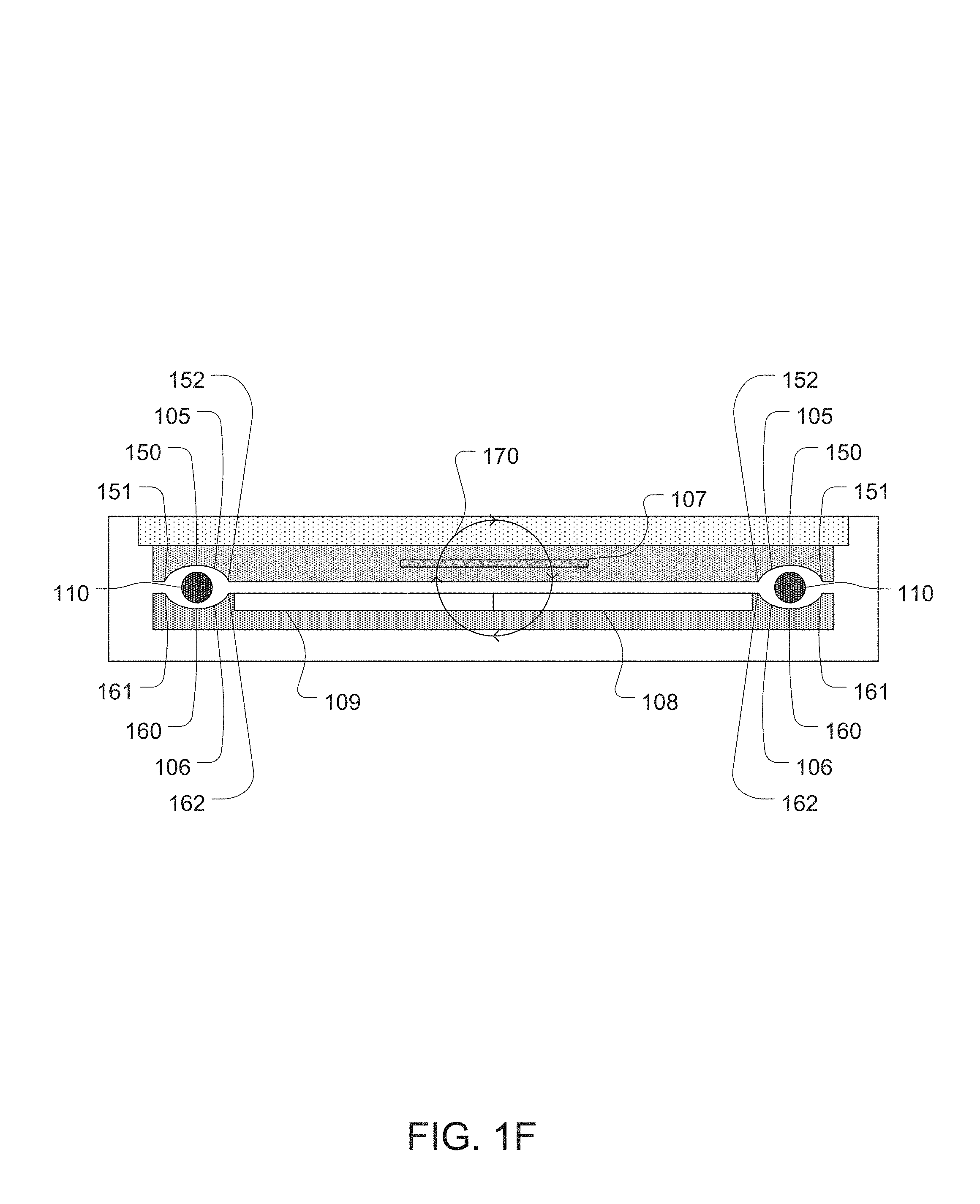
FIG. 1F is a cross sectional side view of the electronic device taken along line 1F in FIG. 1A illustrating an example flow of magnetic flux.
FIG. 1G illustrates a cross sectional side view of an alternative embodiment of the moveable body element of FIG. 1B taken along line 1G of FIG. 1D.
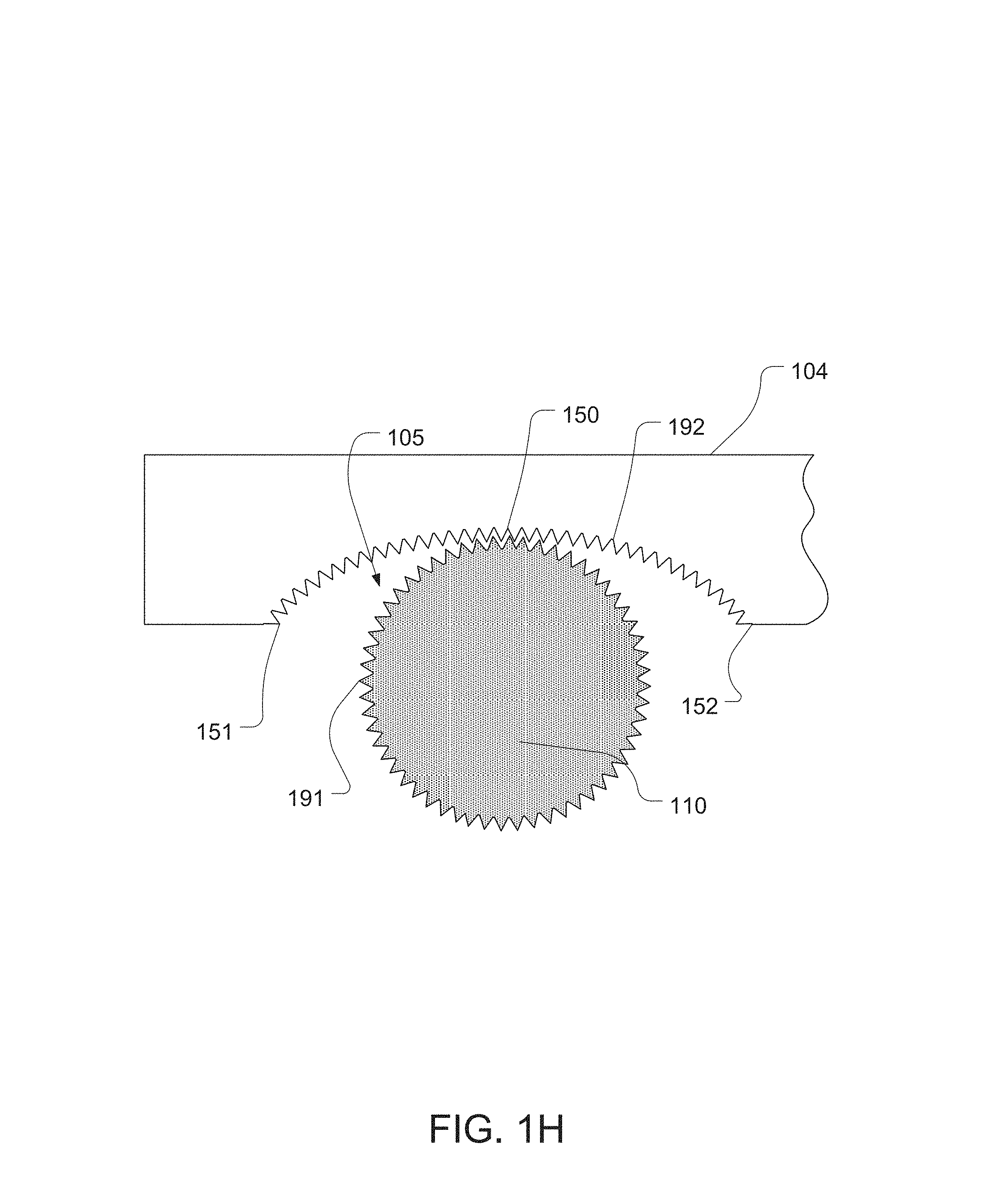
FIG. 1H is a close up side view of an alternative embodiment of the first groove of the fixed body element of FIG. 1E.
FIG. 1I is a cross sectional side view of the electronic device taken along line 1B in FIG. 1A including a second embodiment of a magnetic actuator.
FIG. 1J is a close up view of a bearing and a second groove of FIG. 1I.
FIG. 2A is a cross sectional side view of a first implementation of a third embodiment of a magnetic actuator.
FIG. 2B is a cross sectional side view of a second implementation of the magnetic actuator of FIG. 2A.
FIG. 3A is a cross sectional side view of a first implementation of a fourth embodiment of a magnetic actuator.
FIG. 3B illustrates the magnetic actuator of FIG. 3A after the application of a first electrical current to an electrical coil of the magnetic actuator.
FIG. 3C illustrates the magnetic actuator of FIG. 3B after the application of a second electrical current to the electrical coil of the magnetic actuator.
FIG. 3D is a front plan view of a second implementation of the fourth embodiment of a magnetic actuator.
FIG. 3E is a cross sectional view of the magnetic actuator of FIG. 3D taken along line 3E in FIG. 3D.
FIG. 3F illustrates the magnetic actuator of FIG. 3E after the application of a first electrical current to an electrical coil of the magnetic actuator.
FIG. 3G illustrates the magnetic actuator of FIG. 3F after the application of a second electrical current to the electrical coil of the magnetic actuator.
FIG. 3H illustrates the magnetic actuator of FIG. 3D with a housing surrounding parts of the magnetic actuator.
FIG. 4A is a front view of a first embodiment of a magnetic circuit.
FIG. 4B is a side view of the magnetic circuit of FIG. 4A.
FIG. 4C is a front view of a second embodiment of a magnetic circuit.
FIG. 4D is a front view of a third embodiment of a magnetic circuit.
FIG. 4E is a front view of a fourth embodiment of a magnetic circuit.
DETAILED DESCRIPTION
The description that follows includes sample systems, methods, and computer program products that embody various elements of the present disclosure. However, it should be understood that the described disclosure may be practiced in a variety of forms in addition to those described herein.
In many magnetic actuators, a first body element and a second body element may be connected via one or more centering springs. When the first and second body elements move with respect to each other from an original position, the centering spring may exert a restorative force upon the first and second body elements. This restorative force may operate to bring the first and second body elements back to the original position so that the first and second body elements are positioned for subsequent movement.
The present disclosure discloses magnetic actuators and circuits. In various embodiments, a magnetic actuator or circuit may include a first element that is moveably coupled to a second element via one or more bearings positioned between one or more grooves. In some cases the grooves may be curved. The bearings and the curves may exert a restorative force to return the first and second elements to an original position after movement. In various cases, the bearings may be spherical, cubic, cylindrical, and/or include gear elements that interact with one or more gear elements of the grooves.
In some embodiments, a second element may include one or more electrical coils that are coplanar with a surface of the second element. In various cases, the second element may also include one or more hard magnets positioned in the center of the electrical coil that are polarized to stabilize or destabilize centering of the second element with respect to a first element.
In various embodiments, a magnetic circuit may include a second element with one or more electrical coils wrapped around the second element. In some cases, the electrical coil may include a first section wrapped in a first direction, a second section wrapped in a second direction opposing the first direction, and a middle section that transitions between the first direction and the second direction.
In one or more embodiments, an actuator may include a first element with first and second side soft magnets that is moveably coupled to a second element. Exertion of force may cause the second element to move such that the second body element approaches and/or contacts the first or second soft side magnet. Such contact may result in a "tap," which may be provided to a user as a tactile output. Upon contact, the second element may magnetically attach to the respective soft side magnet and may remain so after the force is no longer exerted until another force is exerted that detaches the second element and causes it to move to approach the other soft side magnet.
In other embodiments, an actuator may include a first magnetic attraction element, a second magnetic attraction element, and a moveable member including a first hard magnet, a second hard magnet, and an electrical coil. Exertion of force may cause the moveable member to move such that the first hard magnet approaches and/or contacts the first magnetic attraction element or the second hard magnet approaches and/or contacts the second magnetic attraction element. Upon contact, the respective hard magnet may magnetically attach to the respective magnetic attraction element and may remain so after the force is no longer exerted until another force is exerted that detaches the respective hard magnet and causes the moveable member to move such that the other hard magnet approaches the other magnetic attraction member.
FIG. 1A is a top view illustrating a track pad 102 incorporated into an electronic device 101. The electronic device may be any electronic device that includes a track pad such as a desktop computer, a laptop computer, a wearable device, a smart phone, a digital media player, a mobile computing device, a tablet computing device, and so on.
FIG. 1B is a cross sectional side view of the electronic device 101 taken along the line 1B in FIG. 1A. As illustrated, a first embodiment of a magnetic actuator 100A is coupled to the track pad 102.
Although the magnetic actuator is illustrated and described herein as coupled to the track pad of the electronic device, it is understood that this is an example. In various implementations, the magnetic actuator may be utilized in a variety of different ways in a variety of different electronic devices. For example, such a magnetic actuator may be coupled to a housing (such as the housing of a tablet computer, mouse, and so on), one or more selection elements (such as one or more keys of a keyboard, buttons of a mouse, touch pads of a tablet computing device, and so on), a wearable device such as a watch, glasses, and so on.
As illustrated, the magnetic actuator may include a fixed body element 104, a number of bearings 110 (which may be spherical), and a moveable body element 103. The fixed body element may include an electrical coil 107 (which may be coplanar with a surface of the fixed body element) and a number of first grooves 105. The moveable body element may include a first hard magnet (materials that are permanently magnetic such as rare-earth magnets) 108, a second hard magnet element 109 (see FIGS. 1D and 1E) (which may have an opposite polarity than the first hard magnet facing a surface of the moveable body element), and a number of second grooves 106. The moveable body element may be attracted to the fixed body element via the first hard magnet and/or the second hard magnet element. The moveable body element may be separated from the fixed body element by the bearings positioned in the first and second grooves.
FIG. 1C is a bottom view of the fixed body element 104. As illustrated, the first grooves may be curved such that the fixed body element grooves are deeper at a center portion 150 than at either edge portion 151 or 152.
FIG. 1D is a top view of the moveable body element 103. As illustrated, the second grooves 106 may be curved such that the moveable body element grooves are deeper at a center portion 160 than at either edge portion 161 or 162.
Application of electrical current to the electrical coil 107 may cause the electrical coil to generate a magnetic field. The magnetic field has a magnetic flux. The magnetic flux may exert a force upon any magnetic material (i.e., the first hard magnet 108 and the second hard magnet 109) within the magnetic field. The vector of the force may vary with the magnetic flux, which may vary according to the position of the magnetic material within the field. This force may cause the moveable body element 103 to move laterally with respect to the fixed body element 104. This movement may cause one or more vibrations, which may be provided to a user as tactile output or feedback. An example of the flow of the magnetic flux 170 can be seen in FIG. 1F.
Thus, returning to FIGS. 1B-1D, when the moveable body element 103 moves laterally with respect to the fixed body element 104 due to the lateral force, the bearing 110 may move from the deeper center portions 150 and 160 to the narrower edge portions 151, 161 or 152, 162 (depending on the direction of motion). This may force the moveable body element further away vertically from the fixed body element. When the lateral force ceases, gravity and/or other forces may then cause the bearing to move from the narrower edge portions 151, 161 or 152, 162 to the deeper center portions 150 and 160. This may allow the moveable body element to move back vertically closer to the fixed body element.
As such, the bearings 110 and the grooves 105 and 106 may interact to exert a restorative force on the moveable body element after movement. This restorative force may operate to return the moveable body element to an original position with respect to the fixed body element after the lateral movement.
FIG. 1E is a close-up side view of a first groove of the fixed body element 104 of FIG. 1C. As illustrated, the center portion 150 is deeper than the edge portions 151 or 152.
With reference again to FIG. 1C, in addition to the center portion 150 of the first grooves 105 being deeper than the edge portions 151 and 152, the grooves may be curved such that the inside portion of the grooves are deeper than their outside portions. As such, the first grooves may be v-shaped cross-sectionally, u-shaped, or similarly shaped. This may cause the sides of the bearings 110 to contact outside portions of the first grooves at two points as opposed to the bottom of the bearings contacting the inside portion of the first grooves (e.g., the bottom of the channel formed by the first grooves). With reference again to FIG. 1D, the second grooves 106 may be similarly curved.
Additionally, although the bearings 110 are illustrated and described above as spherical and the first and second grooves 105 and 106 are shown as curved cross sectionally to correspond to the bearings, it is understood that this is an example. In various implementations, the bearings may be cylindrical and include a plurality of gear elements that are configured to interact with gear elements defined in the first and second grooves. Such an implementation may prevent slippage between the bearings and the first grooves and the second grooves. Such an implementation is illustrated in FIG. 1H, which illustrates gear elements 192 defined in a first groove 105 interacting with gear elements 191 of a cylindrical bearing 110.
FIG. 1F is a cross sectional side view of the electronic device taken along line 1F in FIG. 1A, illustrating an example flow of magnetic flux 170 in response to a specific electrical current applied to the electrical coil 107.
Although the magnetic actuator 100A is illustrated and described above as including four bearings 110, four first grooves 105, and four second grooves 106, it is understood that this is an example. In various implementations, the magnetic actuator may include any number of bearings and/or grooves (such as one, three, or fifteen).
FIG. 1G illustrates a cross sectional side view of an alternative embodiment of the moveable body element 103 of FIG. 1B, taken along line 1G of FIG. 1D. As illustrated, at least one soft magnet 180 (a material that is not permanently magnetic but can become magnetic in response to the proximity of a magnetic force) may be positioned beneath the first hard magnet 108 and/or the second hard magnet 109 such that the first hard magnet and/or the second hard magnet are positioned between the soft magnet and the fixed body element 104. In some implementations, the soft magnet may be composed at least partially of a ferrous metal such as steel.
FIG. 1I is a cross sectional side view of the electronic device taken along line 1B in FIG. 1A, including a second embodiment of a magnetic actuator 100I. As illustrated, in this embodiment the bearings 140 are cubes. Further, the first grooves 105 include curved areas 141 and 143 that curve inward toward center point 142. Similarly, the second grooves 106 include curved areas 145 and 147 that curve inward toward center point 146.
As such, when the moveable body element 103 moves laterally with respect to the fixed body element 104 due to the application of force, the cube bearings may roll along the corresponding curved areas. When the force ceases, gravity and/or other forces may then cause the cube bearings to roll back along the corresponding curved areas. This may provide a restorative force that may operate to return the moveable body element to an original position with respect to the fixed body element after movement.
The relationship between the dimensions of the cube and the dimensions of the curved areas 141, 143, 145, and/or 147 may determine whether or not the cube bearings 140 move the moveable element 103 in a purely lateral direction or whether the cube bearings force the moveable body element to translate vertically as well as laterally.
FIG. 1J is a close up view of a bearing 140 and a second groove 106 of FIG. 1I. The lines 149 indicate the movement of the moveable element 103 that may result based on a center point 148 of the cube bearings. Given the dimensions of the cube bearing illustrated, the center point corresponds to the lowest line 149, which is curved to indicate that the moveable body element would translate vertically during lateral movement. However, if the cube bearing was large enough that the center point corresponded to the top line 149, the moveable body element would only move laterally and would not translate vertically.
Although the moveable body element 103 has been illustrated and described above as moveable with respect to the fixed body element 104, it is understood that this is an example. In various implementations, the body element 104 may be moveable with respect to a fixed body element 103.
FIG. 2A is a cross sectional side view of a first implementation of a third embodiment of a magnetic actuator 200. In some implementations, such a magnetic actuator may be coupled to a device such as the track pad 102 of FIG. 1A.
Returning to FIG. 2A, as illustrated, the magnetic actuator 200 may include a first body element 211 that is moveably coupled to a second body element 212 such that the second body element is capable of lateral movement with respect to the first body element. The first body element may include a soft magnet 201, a first hard magnet 203, and a second hard magnet 204 (which may have an opposite polarity than the first hard magnet facing a surface of the first body element). The second body element may include an electrical coil 205 wound in a circular arrangement to have a first side 206, a second side 207, and a gap in the center. The second body element may also include a center hard magnet 208 positioned in the gap in the center of the electrical coil and a second soft magnet element 202 positioned underneath the electrical coil.
In response to application of an electrical current, the first and second sides of the electrical coil 206 and 207 may generate a magnetic field. The magnetic field has a magnetic flux 209. The magnetic flux may exert a force upon any magnetic material (i.e., the first hard magnet 203 and the second hard magnet 204) within the magnetic field. The vector of the force may vary with the magnetic flux, which may vary according to the position of the magnetic material within the field. This force may cause the second body element 212 to move laterally with respect to the first body element 211. This movement may cause one or more vibrations, which may be provided to a user as tactile output or feedback.
In this first implementation, the center hard magnet 208 may be polarized to oppose the direction of the magnetic flux 209. This opposition may destabilize centering of the first body element 211 with respect to the second body element 212 because the polarities of the sides of the center hard magnet 208 repel the respective polarities of the undersides of the first and second hard magnets 203 and 204. Instead, as a result of the opposition and repulsion, the second body element may be more stable when offset from center in either lateral direction with respect to the first body element than when centered with respect to the first body element. In implementations where the second body element has an original position centered with respect to the first body element, this may cause resistance to the second moveable body element returning to the original centered position with respect to the first moveable body element after the lateral movement 210.
In other implementations, the second body element 212 may have an original position that is offset with respect to the first body element 211 and that may be disrupted by the lateral movement 210 of the second body element. In such implementations, the opposition of the center hard magnet 208 to the direction of the magnetic flux 209 may provide a restorative force after the lateral movement (caused by the repulsion of the sides of the center hard magnet 208 that the respective polarities of the undersides of the first and second hard magnets 203 and 204) that acts to return the second body element to the original offset position with respect to the first body element after the lateral movement of the second body element.
The second body element 212 may be moveably coupled to the first body element 211 utilizing a variety of different mechanisms (not shown). For example, in some implementations the second body element may be suspended from the first body element, such as by wire or string. In other implementations, one or more springs, magnetic forces, and so on may moveably couple the second body element to the first body element.
FIG. 2B is a cross sectional side view of a second implementation of the magnetic actuator of FIG. 2A. In this second implementation, the center hard magnet 208 may be polarized to complement the direction of the magnetic flux 209. This complementing force may exert a restorative force on the first moveable body element and/or the second moveable body element because the polarities of the sides of the center hard magnet 208 attract the respective polarities of the undersides of the first and second hard magnets 203 and 204. Such restorative force may act to return the second body element 212 to an original position with respect to the first body element 211 after the lateral movement 210 of the second body element.
Although the second body element 212 has been illustrated and described above as moveable with respect to the first body element 211, it is understood that this is an example. In various implementations, the first body element may be moveable with respect to the second body element.
FIG. 3A is a cross sectional side view of a first implementation of a fourth embodiment of a magnetic actuator 300A. In some implementations, such a magnetic actuator may be coupled to a device such as the track pad 102 of FIG. 1A.
Returning to FIG. 3A, as illustrated, the magnetic actuator 300A may include a moveable body element 302A that is moveably coupled (such as laterally moveably coupled) to a fixed body element 301A. The fixed body element may include a first hard magnet 306A, a second hard magnet 307A, and a soft magnet 303A. The soft magnet may include a top structure 310A, a first side soft magnet 304A, and a second side soft magnet 305A. The moveable body element may include a base element 309A (which may be at least one soft magnet) and an electrical coil 308A.
Although the fixed body element 301A is illustrated and described as incorporating the top structure 310A, the first side soft magnet 304A, and the second side soft magnet 305A into a single soft magnet 303A, it is understood that this is an example. In other implementations the first side soft magnet, the second side soft magnet, and/or the top structure may be formed of separate soft magnets. Additionally, in various implementations the top structure may not be a soft magnet.
In response to application of an electrical current, the electrical coil 308A may generate a magnetic field. The magnetic field has a magnetic flux. The magnetic flux may exert a force upon any magnetic material (i.e., the first hard magnet 306A and the second hard magnet 307A) within the magnetic field. The vector of the force may vary with the magnetic flux, which may vary according to the position of the magnetic material within the field. This force may cause the moveable body element 302A to approach and/or contact either the first side soft magnet 304A or the second side soft magnet 305A. Such approaches and/or contacts may result in one or more vibrations or taps which may be provided to a user as haptic output or feedback.
When the second moveable body element 302A contacts the first side soft magnet 304A, the second moveable body element may magnetically attach to the first side soft magnet. Subsequently, the second moveable body element may remain magnetically attached to the first side soft magnet even after the electrical current that resulted in the movement of the second moveable body element is no longer applied to the electrical coil 308A. A similar effect may occur when the second moveable body element contacts the second side soft magnet 305A.
FIG. 3B illustrates the magnetic actuator 300A of FIG. 3A after the application of a first electrical current to the electrical coil 308A, resulting in a lateral force being applied to the second moveable body element 302A. As illustrated, the second moveable body element approaches, contacts, and magnetically attaches to the first side soft magnet 304A. This contact may result in a "tap" which may be provided to a user as haptic output or feedback.
The second moveable body element 302A may remain magnetically attached to the first side soft magnet 304A even after the first electrical current is no longer applied to the electrical coil 308A. The second moveable body element may remain magnetically attached to the first side soft magnet until a second electrical current is applied to the electrical coil.
FIG. 3C illustrates the magnetic actuator 300A of FIG. 3B after the application of the second electrical current to the electrical coil 308A, resulting in a lateral force (opposite to the lateral force illustrated in FIG. 3B) being applied to the second moveable body element 302A. As illustrated, the second moveable body element approaches, contacts, and magnetically attaches to the second side soft magnet 305A.
Although the moveable body element 302A has been illustrated and described above as moveable with respect to the fixed body element 301A, it is understood that this is an example. In various implementations, the body element 301A may be moveable with respect to a fixed body element 302A.
FIG. 3D is a front plan view of a second implementation of the fourth embodiment of a magnetic actuator 300B. In some implementations, such a magnetic actuator may be coupled to a device such as the track pad 102 of FIG. 1A.
Returning to FIG. 3D, as illustrated, the magnetic actuator 300B may include a first magnetic attraction element 303B, a second magnetic attraction element 308B, and a moveable member 301B. The first magnetic attraction element may include a first aperture 302B, the second magnetic attraction element may include a second aperture 307B, and the moveable member may be configured to move by passing and/or extending through the first aperture and/or the second aperture. The moveable member may be a shaft and may include a first hard magnet 304B, a second hard magnet 306B, and at least one electrical coil 305B that is at least partially positioned or wrapped around the first hard magnet and/or the second hard magnet.
FIG. 3E is a cross sectional view of the magnetic actuator 300B taken along line 3E in FIG. 3D. As illustrated, the first magnetic attraction element 303B and the second magnetic attraction element 308B may be hard magnets that are polarized towards each other. However, it is understood that this is an example and in various implementations the first magnetic attraction element and the second magnetic attraction element may be soft magnets. Similarly, the first hard magnet 304B and the second hard magnet 306B may be polarized towards each other.
In response to application of an electrical current, the electrical coil 305B may generate a magnetic field. The magnetic field has a magnetic flux. The magnetic flux may exert a force upon any magnetic material (i.e., the first hard magnet 304B and the second hard magnet 306B) within the magnetic field. The vector of the force may vary with the magnetic flux, which may vary according to the position of the magnetic material within the field. This force may cause the moveable member 301B to move such that the first hard magnet 304B approaches and/or contacts the first magnetic attraction element 303B or the second hard magnet 306B approaches and/or contacts the second magnetic attraction element 308B. Such approaches and/or contacts may result in one or more vibrations or taps which may be provided to a user as haptic output or feedback.
When the first hard magnet 304B contacts the first magnetic attraction element 303B, the first hard magnet may magnetically attach to the first magnetic attraction element. Subsequently, the first hard magnet may remain magnetically attached to the first magnetic attraction element even after the force is no longer exerted upon the moveable member 301B. A similar effect may occur when the second hard magnet 306B contacts the second magnetic attraction element 308B.
FIG. 3F illustrates the magnetic actuator 300B of FIG. 3E after the application of a first electrical current to an electrical coil 305B, resulting in a force being applied to the moveable member 301B. As illustrated, the moveable member moves such that the first hard magnet 304B approaches, contacts, and magnetically attaches to the first magnetic attraction element 303B. This contact may result in a "tap" which may be provided to a user as haptic output or feedback.
The first hard magnet 304B may remain magnetically attached to the first magnetic attraction element 303B even after the first electrical current is no longer applied to the electrical coil 305B. The first hard magnet may remain magnetically attached to the first magnetic attraction element a second electrical current is applied to the electrical coil, resulting in a force being applied to the moveable member 301B (opposite to the force shown in FIG. 3F) such that the first hard magnet detaches from the first magnetic attraction element and the second hard magnet 306B approaches the second magnetic attraction element 308B.
FIG. 3G illustrates the magnetic actuator 300B of FIG. 3F after the application of a second electrical current to the electrical coil 305B. As illustrated, the second hard magnet 306B approaches, contacts, and magnetically attaches to the second magnetic attraction element 308B.
FIG. 3H illustrates the magnetic actuator of FIG. 3D with a housing 310B surrounding parts of the magnetic actuator. As illustrated, in some implementations, such a housing may surround the first hard magnet 304B, the second hard magnet 306B, the electrical coil 305B, the first magnetic attraction element 303B, the second magnetic attraction element 308B, and at least part of the moveable member 301B. As also illustrated, the housing may include a first housing aperture 309B and a second housing aperture 311B and the moveable member 301B may be configured to move by passing and/or extending through the first housing aperture and/or the second housing aperture.
FIG. 4A is a front view of a first embodiment of a magnetic circuit 400A. In some implementations, such a magnetic circuit may be a magnetic actuator. In various implementations, such a magnetic circuit may be coupled to a device such as the track pad 102 of FIG. 1A.
Returning to FIG. 4A, as illustrated, the magnetic circuit 400A may include a moveable bar element 401 that is moveably coupled to a fixed bar element 402. The moveable bar element may include a soft magnet 403, a first hard magnet 404, and a second hard magnet 405. The fixed bar element may include an electrical structure 407 (such as a wire, wire insulated in plastic and/or rubber, and/or other electrical coil structure) wound around a bar structure 406 of the fixed bar element.
As illustrated, the electrical coil structure 407 may have a first section 409 that is wound in a first direction around the bar structure 406 and a second section 408 that is wound in a second direction around the bar structure. The first direction may be opposite of the second direction. Further, the electrical coil structure may include a middle section 410 where the winding in the first direction changes to the second direction. In various cases, the middle section may be attached to the bar structure, such as utilizing adhesive.
In response to application of an electrical current, the electrical coil structure 407 may generate a magnetic field. The magnetic field has a magnetic flux 414. The magnetic flux may exert a force upon any magnetic material (i.e., the first hard magnet 404 and the second hard magnet 405) within the magnetic field. The vector of the force may vary with the magnetic flux, which may vary according to the position of the magnetic material within the field. This force may cause the moveable bar element 401 to move laterally with respect to the fixed bar element 402. Such movement may result in one or more vibrations which may be provided to a user as haptic output or feedback.
As illustrated, the moveable bar element 401 may be moveably coupled to portions 412 of the fixed bar element 402 via bearings 413. As illustrated in FIG. 4B, the bearings may be positioned between first grooves 415 and second grooves 416. Movement of the bearings along the first grooves and second grooves may enable the moveable bar element to move laterally with respect to the fixed bar element.
Although the magnetic circuit 400A is illustrated and described as utilizing the bearings 413 to moveably couple the moveable bar element 401 and the fixed bar element 402, it is understood that this is an example. In other implementations, springs or other moveable attachment mechanisms may be utilized to moveably attach the moveable bar element and the fixed bar element.
Although the moveable bar element 401 has been illustrated and described above as moveable with respect to the fixed bar element 402, it is understood that this is an example. In various implementations, the bar element 402 may be moveable with respect to a fixed bar element 401.
FIG. 4C is a front view of a second embodiment of a magnetic circuit 400C. Contrasted with the first embodiment of the magnetic circuit 400A illustrated in FIGS. 4A and 4B, the magnetic circuit 400C may include an additional moveable bar element 450. The additional moveable bar element may be moveably coupled to an opposite side of the fixed bar element 402 from the moveable bar element 401. The additional moveable bar element may be moveably coupled to the fixed bar element via bearings 455.
Further contrasted with the magnetic circuit 400A illustrated in FIGS. 4A and 4B, the moveable bar element 401 of the magnetic circuit 400C may include a first mass adding element 457. The first mass adding element may be positioned between the first hard magnet 404 and the second hard magnet 405 and may function to contribute mass to movement of the first moveable bar element. In some cases, the first mass adding element may be formed from tungsten.
The additional moveable bar element 450 may include a soft magnet 451, a third hard magnet 453, and a fourth hard magnet 452. Additionally, the additional moveable bar element may include a second mass adding element 454. The second mass adding element may be positioned between the third hard magnet and the fourth hard magnet.
FIG. 4D is a front view of a third embodiment of a magnetic circuit 400D. As contrasted with the first embodiment of the magnetic circuit 400A illustrated in FIGS. 4A and 4B, the first grooves 415 and/or the second grooves 416 of the magnetic circuit 400D may include gear elements 461. Additionally, the bearings 413 (which may be cylindrical) may include gear elements 462. Interaction between the gear elements of the bearings and the gear elements of the grooves may enable the moveable bar element to move laterally with respect to the fixed bar element. Such an implementation may prevent slippage between the bearings and the grooves.
Although the magnetic circuit 400D is illustrated and described as utilizing the gear elements 461, 462, and 463 in the same magnetic circuit as the particular electrical coil structure 407, it is understood that this is an example. In other implementations the gear elements 461, 462, and 463 may be utilized to moveably couple various different moveable elements without departing from the scope of the present disclosure. For example, in some implementations the gear elements 461, 462, and 463 may be utilized to moveably couple elements such as the fixed body element 104 and the moveable body element 103 of FIGS. 1B-1E.
FIG. 4E is a front view of a fourth embodiment of a magnetic circuit 400E. As contrasted with the first embodiment of the magnetic circuit 400A illustrated in FIGS. 4A and 4B, the bearings 413 may be cubes. Further, the first grooves 415 may include curved areas 471 and 473 that curve inward toward center point 472. The second grooves 416 may be similarly curved. As such, when the moveable bar element 401 moves laterally with respect to the fixed bar element 402 due to the application of electrical current to the electrical coil structure 407, the cube bearings may roll along the corresponding curved areas. When the lateral movement is ceased, gravity and/or other forces may then cause the cube bearings to roll back along the corresponding curved areas. This may provide a restorative force that may operate to return the moveable bar element to an original position with respect to the fixed bar element after the lateral force is ceased.
The relationship between the dimensions of the cube and the dimensions of the curved areas 471, 473, 474, and/or 476 may determine whether or not the cube bearings 413 move moveable bar element 401 in a purely lateral direction or whether the cube bearings force the moveable body element to translate vertically as well as laterally.
As discussed above and illustrated in the accompanying figures, the present disclosure discloses magnetic actuators and circuits. In various embodiments, a magnetic actuator or circuit may include a moveable element that is moveably coupled to a fixed element via one or more bearings positioned between one or more grooves. In some cases the grooves may be curved. The bearings and the curves may exert a restorative force to return the first and second elements to an original position after movement. In various cases, the bearings may be spherical, cube, cylindrical, and/or include gear elements that interact with one or more gear elements of the grooves.
In some embodiments, a body element may include one or more electrical coils coplanar with a surface of the body element. In various cases, the body element may also include one or more hard magnets positioned in the center of the electrical coil that are polarized to stabilize or destabilize centering of the body element with respect to another element.
In various embodiments, a magnetic circuit may include a bar element with one or more electrical coils wrapped around the bar element. In some cases, the electrical coil may include a first section wrapped in a first direction, a second section wrapped in a second direction opposing the first direction, and a middle section that transitions between the first direction and the second direction.
In one or more embodiments, an actuator may include a fixed element with first and second side soft magnets that is moveably coupled to a moveable element. Exertion of force may cause the moveable element to move such that the moveable body element approaches and/or contacts the first or second soft side magnet. Such contact may result in a "tap," which may be provided to a user as a tactile output. Upon contact, the moveable element may magnetically attach to the respective soft side magnet and may remain so after the force is no longer exerted until another force is exerted that detaches the moveable element and causes it to move to approach the other soft side magnet.
In other embodiments, an actuator may include a first magnetic attraction element, a second magnetic attraction element, and a moveable member including a first hard magnet, a second hard magnet, and an electrical coil. Exertion of force may cause the moveable member to move such that the first hard magnet approaches and/or contacts the first magnetic attraction element or the second hard magnet approaches and/or contacts the second magnetic attraction element. Upon contact, the respective hard magnet may magnetically attach to the respective magnetic attraction element and may remain so after the force is no longer exerted until another force is exerted that detaches the respective hard magnet and causes the moveable member to move such that the other hard magnet approaches the other magnetic attraction member.
In the present disclosure, the methods disclosed may be implemented as sets of instructions or software readable by a device. Further, it is understood that the specific order or hierarchy of steps in the methods disclosed are examples of sample approaches. In other embodiments, the specific order or hierarchy of steps in the method can be rearranged while remaining within the disclosed subject matter. The accompanying method claims present elements of the various steps in a sample order, and are not necessarily meant to be limited to the specific order or hierarchy presented.
The described disclosure may be provided as a computer program product, or software, that may include a non-transitory machine-readable medium having stored thereon instructions, which may be used to program a computer system (or other electronic devices) to perform a process according to the present disclosure. A non-transitory machine-readable medium includes any mechanism for storing information in a form (e.g., software, processing application) readable by a machine (e.g., a computer). The non-transitory machine-readable medium may take the form of, but is not limited to, a magnetic storage medium (e.g., floppy diskette, video cassette, and so on); optical storage medium (e.g., CD-ROM); magneto-optical storage medium; read only memory (ROM); random access memory (RAM); erasable programmable memory (e.g., EPROM and EEPROM); flash memory; and so on.
It is believed that the present disclosure and many of its attendant advantages will be understood by the foregoing description, and it will be apparent that various changes may be made in the form, construction and arrangement of the components without departing from the disclosed subject matter or without sacrificing all of its material advantages. The form described is merely explanatory, and it is the intention of the following claims to encompass and include such changes.
While the present disclosure has been described with reference to various embodiments, it will be understood that these embodiments are illustrative and that the scope of the disclosure is not limited to them. Many variations, modifications, additions, and improvements are possible. More generally, embodiments in accordance with the present disclosure have been described in the context or particular embodiments. Functionality may be separated or combined in blocks differently in various embodiments of the disclosure or described with different terminology. These and other variations, modifications, additions, and improvements may fall within the scope of the disclosure as defined in the claims that follow.
* * * * *
References
D00000
D00001
D00002
D00003
D00004
D00005
D00006
D00007
D00008
D00009
D00010
D00011
D00012

D00013

D00014

D00015

D00016

D00017

D00018

D00019

D00020

D00021

D00022

D00023

D00024

D00025

XML
uspto.report is an independent third-party trademark research tool that is not affiliated, endorsed, or sponsored by the United States Patent and Trademark Office (USPTO) or any other governmental organization. The information provided by uspto.report is based on publicly available data at the time of writing and is intended for informational purposes only.
While we strive to provide accurate and up-to-date information, we do not guarantee the accuracy, completeness, reliability, or suitability of the information displayed on this site. The use of this site is at your own risk. Any reliance you place on such information is therefore strictly at your own risk.
All official trademark data, including owner information, should be verified by visiting the official USPTO website at www.uspto.gov. This site is not intended to replace professional legal advice and should not be used as a substitute for consulting with a legal professional who is knowledgeable about trademark law.