Adapter assembly for interconnecting surgical devices and surgical attachments, and surgical systems thereof
Ingmanson , et al.
U.S. patent number 10,236,616 [Application Number 14/513,283] was granted by the patent office on 2019-03-19 for adapter assembly for interconnecting surgical devices and surgical attachments, and surgical systems thereof. This patent grant is currently assigned to Covidien LP. The grantee listed for this patent is Covidien LP. Invention is credited to Ramiro Cabrera, Matthew Chowaniec, Michael Ingmanson.


| United States Patent | 10,236,616 |
| Ingmanson , et al. | March 19, 2019 |
Adapter assembly for interconnecting surgical devices and surgical attachments, and surgical systems thereof
Abstract
An adapter assembly selectively interconnects a surgical device with a surgical attachment that is configured to perform at least one function. The adapter assembly includes a proximal end that includes at least one mating part adapted to be detachably connected to a surgical device and configured to permit coupling of the adapter assembly to a surgical device in at least a first connection orientation and a second connection orientation.
| Inventors: | Ingmanson; Michael (Stratford, CT), Chowaniec; Matthew (Middletown, CT), Cabrera; Ramiro (Cheshire, CT) | ||||||||||
|---|---|---|---|---|---|---|---|---|---|---|---|
| Applicant: |
|
||||||||||
| Assignee: | Covidien LP (Mansfield,
MA) |
||||||||||
| Family ID: | 52015900 | ||||||||||
| Appl. No.: | 14/513,283 | ||||||||||
| Filed: | October 14, 2014 |
Prior Publication Data
| Document Identifier | Publication Date | |
|---|---|---|
| US 20150150547 A1 | Jun 4, 2015 | |
Related U.S. Patent Documents
| Application Number | Filing Date | Patent Number | Issue Date | ||
|---|---|---|---|---|---|
| 61911774 | Dec 4, 2013 | ||||
| Current U.S. Class: | 1/1 |
| Current CPC Class: | H01R 13/46 (20130101); A61B 17/07207 (20130101); A61B 2017/00477 (20130101); A61B 2017/00367 (20130101); A61B 2017/00464 (20130101); A61B 2017/00734 (20130101); A61B 2017/0046 (20130101); A61B 2017/00389 (20130101); Y10T 29/49117 (20150115); A61B 2017/00398 (20130101) |
| Current International Class: | A61B 17/00 (20060101); A61B 17/072 (20060101); H01R 13/46 (20060101) |
| Field of Search: | ;606/1 |
References Cited [Referenced By]
U.S. Patent Documents
| 2777340 | January 1957 | Hettwer et al. |
| 2957353 | October 1960 | Babacz |
| 3111328 | November 1963 | Di Rito et al. |
| 3695058 | October 1972 | Keith, Jr. |
| 3734515 | May 1973 | Dudek |
| 3759336 | September 1973 | Marcovitz et al. |
| 4162399 | July 1979 | Hudson |
| 4606343 | August 1986 | Conta et al. |
| 4705038 | November 1987 | Sjostrom et al. |
| 4722685 | February 1988 | de Estrada et al. |
| 4823807 | April 1989 | Russell et al. |
| 4874181 | October 1989 | Hsu |
| 5129118 | July 1992 | Walmesley |
| 5129570 | July 1992 | Schulze et al. |
| 5152744 | October 1992 | Krause et al. |
| 5301061 | April 1994 | Nakada et al. |
| 5312023 | May 1994 | Green et al. |
| 5326013 | July 1994 | Green et al. |
| 5350355 | September 1994 | Sklar |
| 5383874 | January 1995 | Jackson et al. |
| 5383880 | January 1995 | Hooven |
| 5389098 | February 1995 | Tsuruta et al. |
| 5395033 | March 1995 | Byrne et al. |
| 5400267 | March 1995 | Denen et al. |
| 5411508 | May 1995 | Bessler et al. |
| 5413267 | May 1995 | Solyntjes et al. |
| 5427087 | June 1995 | Ito et al. |
| 5467911 | November 1995 | Tsuruta et al. |
| 5476379 | December 1995 | Disel |
| 5487499 | January 1996 | Sorrentino et al. |
| 5518163 | May 1996 | Hooven |
| 5518164 | May 1996 | Hooven |
| 5526822 | June 1996 | Burbank et al. |
| 5529235 | June 1996 | Boiarski et al. |
| 5535934 | July 1996 | Boiarski et al. |
| 5535937 | July 1996 | Boiarski et al. |
| 5540375 | July 1996 | Bolanos et al. |
| 5540706 | July 1996 | Aust et al. |
| 5542594 | August 1996 | McKean et al. |
| 5549637 | August 1996 | Crainich |
| 5553675 | September 1996 | Pitzen et al. |
| 5562239 | October 1996 | Boiarski et al. |
| 5564615 | October 1996 | Bishop et al. |
| 5609560 | March 1997 | Ichikawa et al. |
| 5632432 | May 1997 | Schulze et al. |
| 5647526 | July 1997 | Green et al. |
| 5653374 | August 1997 | Young et al. |
| 5658300 | August 1997 | Bito et al. |
| 5667517 | September 1997 | Hooven |
| 5693042 | December 1997 | Boiarski et al. |
| 5704534 | January 1998 | Huitema et al. |
| 5713505 | February 1998 | Huitema |
| 5762603 | June 1998 | Thompson |
| 5779130 | July 1998 | Alesi et al. |
| 5782396 | July 1998 | Mastri et al. |
| 5782397 | July 1998 | Koukline |
| 5797536 | August 1998 | Smith et al. |
| 5820009 | October 1998 | Melling et al. |
| 5863159 | January 1999 | Lasko |
| 5865361 | February 1999 | Milliman et al. |
| 5908427 | June 1999 | McKean et al. |
| 5954259 | September 1999 | Viola et al. |
| 5964774 | October 1999 | McKean et al. |
| 5993454 | November 1999 | Longo |
| 6010054 | January 2000 | Johnson et al. |
| 6017354 | January 2000 | Culp et al. |
| 6032849 | March 2000 | Mastri et al. |
| 6045560 | April 2000 | McKean et al. |
| 6090123 | July 2000 | Culp et al. |
| 6126651 | October 2000 | Mayer |
| 6129547 | October 2000 | Cise et al. |
| 6165169 | December 2000 | Panescu et al. |
| 6239732 | May 2001 | Cusey |
| 6241139 | June 2001 | Milliman et al. |
| 6264086 | July 2001 | McGuckin, Jr. |
| 6264087 | July 2001 | Whitman |
| 6302311 | October 2001 | Adams et al. |
| 6315184 | November 2001 | Whitman |
| 6321855 | November 2001 | Barnes |
| 6329778 | December 2001 | Culp et al. |
| 6343731 | February 2002 | Adams et al. |
| 6348061 | February 2002 | Whitman |
| 6368324 | April 2002 | Dinger et al. |
| 6371909 | April 2002 | Hoeg et al. |
| 6434507 | August 2002 | Clayton et al. |
| 6443973 | September 2002 | Whitman |
| 6461372 | October 2002 | Jensen et al. |
| 6488197 | December 2002 | Whitman |
| 6491201 | December 2002 | Whitman |
| 6533157 | March 2003 | Whitman |
| 6537280 | March 2003 | Dinger et al. |
| 6610066 | August 2003 | Dinger et al. |
| 6611793 | August 2003 | Burnside et al. |
| 6645218 | November 2003 | Cassidy et al. |
| 6654999 | December 2003 | Stoddard et al. |
| 6698643 | March 2004 | Whitman |
| 6699177 | March 2004 | Wang et al. |
| 6716233 | April 2004 | Whitman |
| 6743240 | June 2004 | Smith et al. |
| 6783533 | August 2004 | Green et al. |
| 6792390 | September 2004 | Burnside et al. |
| 6793652 | September 2004 | Whitman et al. |
| 6817508 | November 2004 | Racenet et al. |
| 6830174 | December 2004 | Hillstead et al. |
| 6846308 | January 2005 | Whitman et al. |
| 6846309 | January 2005 | Whitman et al. |
| 6849071 | February 2005 | Whitman et al. |
| 6869320 | March 2005 | Haas |
| 6899538 | May 2005 | Matoba |
| 6905057 | June 2005 | Swayze et al. |
| 6959852 | November 2005 | Shelton, IV et al. |
| 6964363 | November 2005 | Wales et al. |
| 6981628 | January 2006 | Wales |
| 6981941 | January 2006 | Whitman et al. |
| 6986451 | January 2006 | Mastri et al. |
| 6988649 | January 2006 | Shelton, IV et al. |
| 7032798 | April 2006 | Whitman et al. |
| RE39152 | June 2006 | Aust et al. |
| 7055731 | June 2006 | Shelton, IV et al. |
| 7059508 | June 2006 | Shelton, IV et al. |
| 7077856 | July 2006 | Whitman |
| 7111769 | September 2006 | Wales et al. |
| 7122029 | October 2006 | Koop et al. |
| 7140528 | November 2006 | Shelton, IV |
| 7143923 | December 2006 | Shelton, IV et al. |
| 7143925 | December 2006 | Shelton, IV et al. |
| 7143926 | December 2006 | Shelton, IV et al. |
| 7147138 | December 2006 | Shelton, IV |
| 7172104 | February 2007 | Scirica et al. |
| 7225964 | June 2007 | Mastri et al. |
| 7238021 | July 2007 | Johnson |
| 7246734 | July 2007 | Shelton, IV |
| 7328828 | February 2008 | Ortiz et al. |
| 7364061 | April 2008 | Swayze et al. |
| 7380695 | June 2008 | Doll et al. |
| 7380696 | June 2008 | Shelton, IV et al. |
| 7404508 | July 2008 | Smith et al. |
| 7407078 | August 2008 | Shelton, IV et al. |
| 7416101 | August 2008 | Shelton, IV et al. |
| 7419080 | September 2008 | Smith et al. |
| 7422139 | September 2008 | Shelton, IV et al. |
| 7431189 | October 2008 | Shelton, IV et al. |
| 7441684 | October 2008 | Shelton, IV et al. |
| 7448525 | November 2008 | Shelton, IV et al. |
| 7464846 | December 2008 | Shelton, IV et al. |
| 7464847 | December 2008 | Viola et al. |
| 7464849 | December 2008 | Shelton, IV et al. |
| 7481347 | January 2009 | Roy |
| 7481824 | January 2009 | Boudreaux et al. |
| 7487899 | February 2009 | Shelton, IV et al. |
| 7549564 | June 2009 | Boudreaux |
| 7565993 | July 2009 | Milliman et al. |
| 7568603 | August 2009 | Shelton, IV et al. |
| 7575144 | August 2009 | Ortiz et al. |
| 7588175 | September 2009 | Timm et al. |
| 7588176 | September 2009 | Timm et al. |
| 7637409 | December 2009 | Marczyk |
| 7641093 | January 2010 | Doll et al. |
| 7644848 | January 2010 | Swayze et al. |
| 7670334 | March 2010 | Hueil et al. |
| 7673780 | March 2010 | Shelton, IV et al. |
| 7699835 | April 2010 | Lee et al. |
| 7721931 | May 2010 | Shelton, IV et al. |
| 7738971 | June 2010 | Swayze et al. |
| 7740159 | June 2010 | Shelton, IV et al. |
| 7743960 | June 2010 | Whitman et al. |
| 7758613 | July 2010 | Whitman |
| 7766210 | August 2010 | Shelton, IV et al. |
| 7770773 | August 2010 | Whitman et al. |
| 7770775 | August 2010 | Shelton, IV et al. |
| 7793812 | September 2010 | Moore et al. |
| 7799039 | September 2010 | Shelton, IV et al. |
| 7802712 | September 2010 | Milliman et al. |
| 7803151 | September 2010 | Whitman |
| 7822458 | October 2010 | Webster, III et al. |
| 7845534 | December 2010 | Viola et al. |
| 7845537 | December 2010 | Shelton, IV et al. |
| 7857185 | December 2010 | Swayze et al. |
| 7870989 | January 2011 | Viola et al. |
| 7905897 | March 2011 | Whitman et al. |
| 7918230 | April 2011 | Whitman et al. |
| 7922061 | April 2011 | Shelton, IV et al. |
| 7922719 | April 2011 | Ralph et al. |
| 7947034 | May 2011 | Whitman |
| 7951071 | May 2011 | Whitman et al. |
| 7954682 | June 2011 | Giordano et al. |
| 7959051 | June 2011 | Smith et al. |
| 7963433 | June 2011 | Whitman |
| 7967178 | June 2011 | Scirica et al. |
| 7967179 | June 2011 | Olson et al. |
| 7992758 | August 2011 | Whitman et al. |
| 8016178 | September 2011 | Olson et al. |
| 8016855 | September 2011 | Whitman et al. |
| 8020743 | September 2011 | Shelton, IV |
| 8025199 | September 2011 | Whitman et al. |
| 8035487 | October 2011 | Malackowski |
| 8052024 | November 2011 | Viola et al. |
| 8056787 | November 2011 | Boudreaux et al. |
| 8114118 | February 2012 | Knodel et al. |
| 8132705 | March 2012 | Viola et al. |
| 8152516 | April 2012 | Harvey et al. |
| 8157150 | April 2012 | Viola et al. |
| 8157151 | April 2012 | Ingmanson et al. |
| 8182494 | May 2012 | Yencho et al. |
| 8186555 | May 2012 | Shelton, IV et al. |
| 8186587 | May 2012 | Zmood et al. |
| 8220367 | July 2012 | Hsu |
| 8235273 | August 2012 | Olson et al. |
| 8241322 | August 2012 | Whitman et al. |
| 8272554 | September 2012 | Whitman et al. |
| 8292150 | October 2012 | Bryant |
| 8292888 | October 2012 | Whitman |
| 8303581 | November 2012 | Arts et al. |
| 8342379 | January 2013 | Whitman et al. |
| 8348855 | January 2013 | Hillely et al. |
| 8353440 | January 2013 | Whitman et al. |
| 8357144 | January 2013 | Whitman et al. |
| 8365633 | February 2013 | Simaan et al. |
| 8365972 | February 2013 | Aranyi et al. |
| 8371492 | February 2013 | Aranyi et al. |
| 8372057 | February 2013 | Cude et al. |
| 8391957 | March 2013 | Carlson et al. |
| 8424739 | April 2013 | Racenet et al. |
| 8454585 | June 2013 | Whitman |
| 8505802 | August 2013 | Viola et al. |
| 8517241 | August 2013 | Nicholas et al. |
| 8551076 | October 2013 | Duval et al. |
| 8561871 | October 2013 | Rajappa et al. |
| 8623000 | January 2014 | Humayun et al. |
| 8632463 | January 2014 | Drinan et al. |
| 8647258 | February 2014 | Aranyi et al. |
| 8657174 | February 2014 | Yates et al. |
| 8657177 | February 2014 | Scirica et al. |
| 8672206 | March 2014 | Aranyi et al. |
| 8696552 | April 2014 | Whitman |
| 8708213 | April 2014 | Shelton, IV et al. |
| 8752749 | June 2014 | Moore et al. |
| 8758391 | June 2014 | Swayze et al. |
| 8806973 | August 2014 | Ross et al. |
| 8851355 | October 2014 | Aranyi et al. |
| 8858571 | October 2014 | Shelton, IV et al. |
| 8875972 | November 2014 | Weisenburgh, II et al. |
| 8893946 | November 2014 | Boudreaux et al. |
| 8899462 | December 2014 | Kostrzewski et al. |
| 8939344 | January 2015 | Olson et al. |
| 8960519 | February 2015 | Whitman et al. |
| 8961396 | February 2015 | Azarbarzin et al. |
| 8967443 | March 2015 | McCuen |
| 8968276 | March 2015 | Zemlok et al. |
| 8968337 | March 2015 | Whitfield et al. |
| 8992422 | March 2015 | Spivey et al. |
| 9064653 | June 2015 | Prest et al. |
| 9113875 | August 2015 | Viola et al. |
| 9216013 | December 2015 | Scirica et al. |
| 9282961 | March 2016 | Whitman et al. |
| 9282963 | March 2016 | Bryant |
| 9295522 | March 2016 | Kostrzewski |
| 9307986 | April 2016 | Hall et al. |
| 2001/0031975 | October 2001 | Whitman et al. |
| 2002/0049454 | April 2002 | Whitman et al. |
| 2002/0165541 | November 2002 | Whitman |
| 2003/0038938 | February 2003 | Jung et al. |
| 2003/0165794 | September 2003 | Matoba |
| 2004/0111012 | June 2004 | Whitman |
| 2004/0133189 | July 2004 | Sakurai |
| 2004/0176751 | September 2004 | Weitzner et al. |
| 2004/0193146 | September 2004 | Lee et al. |
| 2005/0131442 | June 2005 | Yachia et al. |
| 2006/0142656 | June 2006 | Malackowski et al. |
| 2006/0142740 | June 2006 | Sherman et al. |
| 2006/0142744 | June 2006 | Boutoussov |
| 2006/0259073 | November 2006 | Miyamoto et al. |
| 2006/0278680 | December 2006 | Viola et al. |
| 2007/0023476 | February 2007 | Whitman et al. |
| 2007/0023477 | February 2007 | Whitman |
| 2007/0029363 | February 2007 | Popov |
| 2007/0055219 | March 2007 | Whitman et al. |
| 2007/0084897 | April 2007 | Shelton et al. |
| 2007/0102472 | May 2007 | Shelton |
| 2007/0152014 | July 2007 | Gillum et al. |
| 2007/0175947 | August 2007 | Ortiz et al. |
| 2007/0175949 | August 2007 | Shelton et al. |
| 2007/0175950 | August 2007 | Shelton et al. |
| 2007/0175951 | August 2007 | Shelton et al. |
| 2007/0175955 | August 2007 | Shelton et al. |
| 2007/0175961 | August 2007 | Shelton et al. |
| 2008/0029570 | February 2008 | Shelton et al. |
| 2008/0029573 | February 2008 | Shelton et al. |
| 2008/0029574 | February 2008 | Shelton et al. |
| 2008/0029575 | February 2008 | Shelton et al. |
| 2008/0058801 | March 2008 | Taylor et al. |
| 2008/0109012 | May 2008 | Falco et al. |
| 2008/0110958 | May 2008 | McKenna et al. |
| 2008/0167736 | July 2008 | Swayze et al. |
| 2008/0185419 | August 2008 | Smith et al. |
| 2008/0188841 | August 2008 | Tomasello et al. |
| 2008/0197167 | August 2008 | Viola et al. |
| 2008/0208195 | August 2008 | Shores et al. |
| 2008/0237296 | October 2008 | Boudreaux et al. |
| 2008/0251561 | October 2008 | Eades et al. |
| 2008/0255413 | October 2008 | Zemlok et al. |
| 2008/0255607 | October 2008 | Zemlok |
| 2008/0262654 | October 2008 | Omori et al. |
| 2008/0308603 | December 2008 | Shelton et al. |
| 2009/0090763 | April 2009 | Zemlok et al. |
| 2009/0099876 | April 2009 | Whitman |
| 2009/0138006 | May 2009 | Bales et al. |
| 2009/0171147 | July 2009 | Lee et al. |
| 2009/0182193 | July 2009 | Whitman et al. |
| 2009/0209990 | August 2009 | Yates |
| 2009/0254094 | October 2009 | Knapp et al. |
| 2009/0314821 | December 2009 | Racenet |
| 2010/0069942 | March 2010 | Shelton, IV |
| 2010/0193568 | August 2010 | Scheib et al. |
| 2010/0211053 | August 2010 | Ross et al. |
| 2010/0225073 | September 2010 | Porter et al. |
| 2011/0006101 | January 2011 | Hall et al. |
| 2011/0017801 | January 2011 | Zemlok et al. |
| 2011/0071508 | March 2011 | Duval et al. |
| 2011/0077673 | March 2011 | Grubac et al. |
| 2011/0121049 | May 2011 | Malinouskas et al. |
| 2011/0125138 | May 2011 | Malinouskas et al. |
| 2011/0139851 | June 2011 | McCuen |
| 2011/0155783 | June 2011 | Rajappa et al. |
| 2011/0155786 | June 2011 | Shelton, IV |
| 2011/0172648 | July 2011 | Jeong |
| 2011/0174099 | July 2011 | Ross |
| 2011/0204119 | August 2011 | McCuen |
| 2011/0218522 | September 2011 | Whitman |
| 2011/0253765 | October 2011 | Nicholas |
| 2011/0276057 | November 2011 | Conlon et al. |
| 2011/0290854 | December 2011 | Timm et al. |
| 2011/0295242 | December 2011 | Spivey et al. |
| 2011/0295269 | December 2011 | Swensgard et al. |
| 2012/0000962 | January 2012 | Racenet et al. |
| 2012/0074199 | March 2012 | Olson et al. |
| 2012/0089131 | April 2012 | Zemlok |
| 2012/0104071 | May 2012 | Bryant |
| 2012/0116368 | May 2012 | Viola |
| 2012/0143002 | June 2012 | Aranyi et al. |
| 2012/0172924 | July 2012 | Allen, IV |
| 2012/0223121 | September 2012 | Viola et al. |
| 2012/0245428 | September 2012 | Smith et al. |
| 2012/0253329 | October 2012 | Zemlok et al. |
| 2012/0310220 | December 2012 | Malkowski et al. |
| 2012/0323226 | December 2012 | Chowaniec et al. |
| 2012/0330285 | December 2012 | Hartoumbekis |
| 2013/0018361 | January 2013 | Bryant |
| 2013/0093149 | April 2013 | Saur et al. |
| 2013/0098966 | April 2013 | Kostrzewski et al. |
| 2013/0098968 | April 2013 | Aranyi et al. |
| 2013/0098969 | April 2013 | Scirica et al. |
| 2013/0181035 | July 2013 | Milliman |
| 2013/0184704 | July 2013 | Beardsley et al. |
| 2013/0214025 | August 2013 | Zemlok et al. |
| 2013/0240596 | September 2013 | Whitman |
| 2013/0274722 | October 2013 | Kostrzewski et al. |
| 2013/0282052 | October 2013 | Aranyi et al. |
| 2013/0292451 | November 2013 | Viola et al. |
| 2013/0313304 | November 2013 | Shelton, IV et al. |
| 2013/0317486 | November 2013 | Nicholas et al. |
| 2013/0319706 | December 2013 | Nicholas et al. |
| 2013/0324978 | December 2013 | Nicholas et al. |
| 2013/0324979 | December 2013 | Nicholas et al. |
| 2013/0334281 | December 2013 | Williams |
| 2014/0012236 | January 2014 | Williams et al. |
| 2014/0012237 | January 2014 | Pribanic et al. |
| 2014/0012289 | January 2014 | Snow et al. |
| 2014/0025046 | January 2014 | Williams et al. |
| 2014/0110455 | April 2014 | Ingmanson et al. |
| 2014/0144970 | May 2014 | Aranyi et al. |
| 2014/0207125 | July 2014 | Applegate et al. |
| 2014/0207182 | July 2014 | Zergiebel et al. |
| 2014/0207185 | July 2014 | Goble et al. |
| 2014/0236173 | August 2014 | Scirica et al. |
| 2014/0236174 | August 2014 | Williams et al. |
| 2014/0276932 | September 2014 | Williams et al. |
| 2014/0299647 | October 2014 | Scirica et al. |
| 2014/0303668 | October 2014 | Nicholas et al. |
| 2014/0358129 | December 2014 | Zergiebel et al. |
| 2014/0361068 | December 2014 | Aranyi et al. |
| 2014/0373652 | December 2014 | Zergiebel et al. |
| 2015/0048144 | February 2015 | Whitman |
| 2015/0076205 | March 2015 | Zergiebel |
| 2015/0080912 | March 2015 | Sapre |
| 2015/0157321 | June 2015 | Zergiebel et al. |
| 2015/0164502 | June 2015 | Richard et al. |
| 2015/0272577 | October 2015 | Zemlok et al. |
| 2015/0297199 | October 2015 | Nicholas et al. |
| 2015/0303996 | October 2015 | Calderoni |
| 2015/0320420 | November 2015 | Penna et al. |
| 2015/0327850 | November 2015 | Kostrzewski |
| 2015/0342601 | December 2015 | Williams et al. |
| 2015/0342603 | December 2015 | Zergiebel et al. |
| 2015/0374366 | December 2015 | Zergiebel et al. |
| 2015/0374370 | December 2015 | Zergiebel et al. |
| 2015/0374371 | December 2015 | Richard et al. |
| 2015/0374372 | December 2015 | Zergiebel et al. |
| 2015/0374449 | December 2015 | Chowaniec et al. |
| 2015/0380187 | December 2015 | Zergiebel et al. |
| 2016/0095585 | April 2016 | Zergiebel et al. |
| 2016/0095596 | April 2016 | Scirica et al. |
| 2016/0106406 | April 2016 | Cabrera et al. |
| 2016/0113648 | April 2016 | Zergiebel et al. |
| 2016/0113649 | April 2016 | Zergiebel et al. |
| 2008229795 | Apr 2009 | AU | |||
| 2451558 | Jan 2003 | CA | |||
| 101856251 | Oct 2010 | CN | |||
| 102068289 | May 2011 | CN | |||
| 102247182 | Nov 2011 | CN | |||
| 102008053842 | May 2010 | DE | |||
| 0634144 | Jan 1995 | EP | |||
| 0648476 | Apr 1995 | EP | |||
| 0686374 | Dec 1995 | EP | |||
| 0705571 | Apr 1996 | EP | |||
| 1690502 | Aug 2006 | EP | |||
| 1723913 | Nov 2006 | EP | |||
| 1736112 | Dec 2006 | EP | |||
| 1759652 | Mar 2007 | EP | |||
| 1769754 | Apr 2007 | EP | |||
| 1772105 | Apr 2007 | EP | |||
| 1 813 203 | Aug 2007 | EP | |||
| 1813199 | Aug 2007 | EP | |||
| 1813211 | Aug 2007 | EP | |||
| 1908412 | Apr 2008 | EP | |||
| 1917929 | May 2008 | EP | |||
| 1943954 | Jul 2008 | EP | |||
| 1943956 | Jul 2008 | EP | |||
| 1943958 | Jul 2008 | EP | |||
| 1943976 | Jul 2008 | EP | |||
| 1952769 | Aug 2008 | EP | |||
| 2005898 | Dec 2008 | EP | |||
| 2027819 | Feb 2009 | EP | |||
| 2044890 | Apr 2009 | EP | |||
| 2055243 | May 2009 | EP | |||
| 2090247 | Aug 2009 | EP | |||
| 2098170 | Sep 2009 | EP | |||
| 2100561 | Sep 2009 | EP | |||
| 2100562 | Sep 2009 | EP | |||
| 2165664 | Mar 2010 | EP | |||
| 2236098 | Oct 2010 | EP | |||
| 2245994 | Nov 2010 | EP | |||
| 2263568 | Dec 2010 | EP | |||
| 2272443 | Jan 2011 | EP | |||
| 2316345 | May 2011 | EP | |||
| 2324776 | May 2011 | EP | |||
| 2329773 | Jun 2011 | EP | |||
| 2333509 | Jun 2011 | EP | |||
| 2377472 | Oct 2011 | EP | |||
| 2462878 | Jun 2012 | EP | |||
| 2462880 | Jun 2012 | EP | |||
| 2491872 | Aug 2012 | EP | |||
| 2586382 | May 2013 | EP | |||
| 2606834 | Jun 2013 | EP | |||
| 2668910 | Dec 2013 | EP | |||
| 2676615 | Dec 2013 | EP | |||
| 2815705 | Dec 2014 | EP | |||
| 2333509 | Feb 2010 | ES | |||
| 2861574 | May 2005 | FR | |||
| 08-038488 | Feb 1996 | JP | |||
| 2005-125075 | May 2005 | JP | |||
| 20120022521 | Mar 2012 | KR | |||
| 99/15086 | Apr 1999 | WO | |||
| 2000/072760 | Dec 2000 | WO | |||
| 2000/072765 | Dec 2000 | WO | |||
| 2003/000138 | Jan 2003 | WO | |||
| 2003/026511 | Apr 2003 | WO | |||
| 2003/030743 | Apr 2003 | WO | |||
| 2003065916 | Aug 2003 | WO | |||
| 2003/077769 | Sep 2003 | WO | |||
| 2003090630 | Nov 2003 | WO | |||
| 2004/107989 | Dec 2004 | WO | |||
| 2006/042210 | Apr 2006 | WO | |||
| 2007016290 | Feb 2007 | WO | |||
| 2007/026354 | Mar 2007 | WO | |||
| 2007137304 | Nov 2007 | WO | |||
| 2008/131362 | Oct 2008 | WO | |||
| 2008/133956 | Nov 2008 | WO | |||
| 2009039506 | Mar 2009 | WO | |||
| 2007014355 | Apr 2009 | WO | |||
| 2009/132359 | Oct 2009 | WO | |||
| 2009/143092 | Nov 2009 | WO | |||
| 2009149234 | Dec 2009 | WO | |||
| 2011/108840 | Sep 2011 | WO | |||
| 2012040984 | Apr 2012 | WO | |||
Other References
|
Extended European Search Report corresponding to International Application No. EP 15 15 1076.5 dated Apr. 22, 2015. cited by applicant . Japanese Office Action corresponding to International Application No. JP 2011-084092 dated Jan. 14, 2016. cited by applicant . Extended European Search Report corresponding to International Application No. EP 12 19 7970.2 dated Jan. 28, 2016. cited by applicant . Chinese Office Action corresponding to International Application No. CN 201210560638.1 dated Oct. 21, 2015. cited by applicant . European Office Action corresponding to International Application No. EP 14 15 9056.2 dated Oct. 26, 2015. cited by applicant . Australian Examination Report No. 1 corresponding to International Application No. AU 2015200153 dated Dec. 11, 2015. cited by applicant . Australian Examination Report No. 1 corresponding to International Application No. AU 2014204542 dated Jan. 7, 2016. cited by applicant . Chinese Office Action corresponding to International Application No. CN 201310125449.6 dated Feb. 3, 2016. cited by applicant . Extended European Search Report corresponding to International Application No. EP 15 19 0245.9 dated Jan. 28, 2016. cited by applicant . Extended European Search Report corresponding to International Application No. EP 15 16 7793.7 dated Apr. 5, 2016. cited by applicant . European Office Action corresponding to International Application No. EP 14 18 4882.0 dated Apr. 25, 2016. cited by applicant . Extended European Search Report corresponding to International Application No. EP 14 19 6704.2 dated Sep. 24, 2015. cited by applicant . International Search Report and Written Opinion corresponding to Int'l Appln. No. PCT/US2015/051837, dated Dec. 21, 2015. cited by applicant . Extended European Search Report corresponding to International Application No. EP 14 19 7563.1 dated Aug. 5, 2015. cited by applicant . Partial European Search Report corresponding to International Application No. EP 15 19 0643.5 dated Feb. 26, 2016. cited by applicant . Extended European Search Report corresponding to International Application No. EP 15 16 6899.3 dated Feb. 3, 2016. cited by applicant . Extended European Search Report corresponding to International Application No. EP 14 19 9783.3 dated Dec. 22, 2015. cited by applicant . Extended European Search Report corresponding to International Application No. EP 15 17 3807.7 dated Nov. 24, 2015. cited by applicant . Extended European Search Report corresponding to International Application No. EP 15 19 0760.7 dated Apr. 1, 2016. cited by applicant . Extended European Search Report corresponding to International Application No. EP 15 17 3803.6 dated Nov. 24, 2015. cited by applicant . Extended European Search Report corresponding to International Application No. EP 15 17 3804.4 dated Nov. 24, 2015. cited by applicant . Extended European Search Report corresponding to International Application No. EP 15 18 8539.9 dated Feb. 17, 2016. cited by applicant . Extended European Search Report corresponding to International Application No. EP 15 17 3910.9 dated Nov. 13, 2015. cited by applicant . European Office Action corresponding to International Application No. EP 14 15 2236.7 dated Aug. 11, 2015. cited by applicant . Extended European Search Report corresponding to International Application No. EP 15 18 4915.5 dated Jan. 5, 2016. cited by applicant . European Search Report dated Sep. 20, 2017, corresponding to European Application No. 17176329.5; 10 pages. cited by applicant . European Search Report, dated Apr. 13, 2015, corresponding to European Patent Application No. 14196027.8; 9 pages. cited by applicant . Chinese Office Action (with English translation), dated Feb. 7, 2018, corresponding to Chinese Application No. 2014107349051; 22 total pages. cited by applicant. |
Primary Examiner: Downey; John R
Parent Case Text
CROSS-REFERENCE TO RELATED APPLICATIONS
This application claims the benefit of and priority to U.S. Provisional Patent Application No. 61/911,774, filed Dec. 4, 2013, the entire disclosure of which is incorporated by reference herein
Claims
What is claimed is:
1. An electromechanical surgical system, comprising: a hand-held electromechanical surgical device configured to actuate a surgical attachment, the surgical device including: a housing; first and second actuators each being configured to actuate a different function of the surgical attachment; and at least one motor disposed with the housing for driving actuation of the surgical attachment; and an adapter assembly for selectively interconnecting the surgical device with the surgical attachment, the adapter assembly being in operative communication with the at least one motor and including at least one mating part adapted to be detachably connected to the surgical device and configured to permit coupling of the adapter assembly to the surgical device in at least a first connection orientation and a second connection orientation, wherein in the first connection orientation the first actuator is configured to actuate a first function of the surgical attachment and the second actuator is configured to actuate a second function of the surgical attachment, and in the second connection orientation the first actuator is configured to actuate the second function of the surgical attachment and the second actuator is configured to actuate the first function of the surgical attachment.
2. An electromechanical surgical system as recited in claim 1, wherein the first and second actuators include user input buttons.
3. An electromechanical surgical system as recited in claim 1, wherein the at least one motor includes a first motor adapted to be connected with a first drive shaft of the adapter assembly for performing the first function of the surgical attachment and a second motor adapted to be connected with a second drive shaft of the adapter assembly for performing the second function of the surgical attachment.
4. An electromechanical surgical system as recited in claim 3, wherein in the first connection orientation the first motor is coupled with the first drive shaft and the second motor is coupled with the second drive shaft, and in the second connection orientation the first motor is coupled with the second drive shaft and the second motor is coupled with the first drive shaft.
5. An electromechanical surgical system as recited in claim 1, wherein the adapter assembly is configured to interchange functions actuated by the surgical device when the adapter assembly moves between the first connection orientation and the second connection orientation.
6. An electromechanical surgical system as recited in claim 1, wherein the at least one mating part includes an electrical connector adapted for connection with an electrical connector of the surgical device.
7. An electromechanical surgical system, comprising: a hand-held electromechanical surgical device configured to actuate a surgical attachment, the surgical device including: a housing; a first motor disposed with the housing; and a second motor disposed with the housing; and an adapter assembly for selectively interconnecting the surgical device with the surgical attachment, the adapter assembly including: at least one mating part adapted to be detachably connected to the surgical device and configured to permit coupling of the adapter assembly to the surgical device in at least a first connection orientation and a second connection orientation; a first drive shaft configured to actuate a first function of the surgical attachment; and a second drive shaft configured to actuate a second function of the surgical attachment, wherein in the first connection orientation the first motor is coupled with the first drive shaft and the second motor is coupled with the second drive shaft, and in the second connection orientation the first motor is coupled with the second drive shaft and the second motor is coupled with the first drive shaft.
Description
BACKGROUND
1. Technical Field
The present disclosure relates to adapter assemblies for use in surgical systems. More specifically, the present disclosure relates to adapter assemblies for use with electromechanical surgical devices to electrically and mechanically interconnect electromechanical surgical devices and surgical attachments, such as, for example, surgical loading units. Surgical systems including hand held electromechanical surgical devices and adapter assemblies for connecting surgical loading units to a hand held electromechanical surgical device are also described.
2. Background of Related Art
A number of surgical device manufacturers have developed product lines with proprietary drive systems for operating and/or manipulating electromechanical surgical devices. In many instances the electromechanical surgical devices include a handle assembly, which is reusable, and disposable loading units and/or single use loading units. The loading units are selectively connected to the handle assembly prior to use and then disconnected from the handle assembly following use in order to be disposed of or in some instances sterilized for re-use.
In certain instances, an adapter assembly is used to interconnect an electromechanical surgical device with any one of a number of surgical attachments, such as, for example, surgical loading units, to establish a mechanical and/or electrical connection therebetween. Presently, however, electromechanical surgical devices are limited to being connected with adapter assemblies in only one connection orientation, which limits a versatility and a comfort of use of the surgical device. For example, if a practitioner reverses an orientation of a surgical device relative to his or her hand, the actuators used to actuate the functions of the surgical attachment will also be reversed relative to the practitioner's hand, making operation of the surgical device unfamiliar to the practitioner.
Further, surgical devices often include several motors used to drive the function of different parts of a surgical attachment. Each part requires a unique amount of torque, speed and/or runtime, which leads to an inconsistent lifespan for each motor. Also, if a particular motor were to fail, a specific function of the surgical attachment driven by that motor would become non-operational.
Accordingly, a need exists for an adapter assembly that can connect to a surgical device and/or a surgical attachment in more than one connection orientation so that an electromechanical surgical system can be provided that overcomes at least the above-mentioned deficiencies of the prior art.
SUMMARY
In one aspect, the present disclosure relates to adapter assemblies for use with electromechanical surgical devices to electrically and mechanically interconnect electromechanical surgical devices and surgical attachments. In another aspect, the present disclosure relates to surgical systems including hand held electromechanical surgical devices and adapter assemblies for connecting surgical attachments to the hand held electromechanical surgical devices.
According to an aspect of the present disclosure, adapter assemblies for selectively interconnecting a surgical device with a surgical attachment are provided. In embodiments, the adapter assembly has a proximal end that includes at least one mating part adapted to be detachably connected to a surgical device. The at least one mating part may be configured to permit coupling of the adapter assembly to the surgical device in at least a first connection orientation and a second connection orientation.
In embodiments, the at least one mating part includes a plurality of mating parts aligned in a symmetrical configuration. In embodiments, the adapter assembly is configured to determine a connection orientation with the surgical device. The adapter assembly may be configured to interchange functions actuated by the surgical device when the connection orientation moves between the first connection orientation and the second connection orientation.
In embodiments, the adapter assembly is configured to reverse functions actuated by at least two actuators of the surgical device when the connection orientation rotates between the first connection orientation and the second connection orientation.
In embodiments, the at least one mating part includes an electrical connector adapted to be connected to an electrical connector of the surgical device such that the electrical connector of the at least one mating part determines the connection orientation between the adapter assembly and the surgical device.
According to another aspect of the present disclosure, an electromechanical surgical system is provided. In embodiments, the electromechanical surgical system comprises a hand-held electromechanical surgical device configured to actuate a surgical attachment. The surgical device may include a housing and at least one motor disposed with the housing for driving movement of the surgical attachment. An adapter assembly may selectively interconnect the surgical device with the surgical attachment. In embodiments, the adapter assembly is in operative communication with the at least one motor. The adapter assembly may include at least one mating part adapted to be detachably connected with at least one of the surgical device and the surgical attachment. In embodiments, the at least one mating part is configured to permit coupling of the adapter assembly to the surgical device in at least a first connection orientation and a second connection orientation.
In embodiments, the surgical device includes a first actuator and a second actuator. The actuators may be configured to actuate a different function of the surgical attachment. In embodiments, in the first connection orientation the first actuator actuates a first function of the surgical attachment and the second actuator actuates a second function of the surgical attachment. In the second connection orientation the first actuator may actuate the second function and the second actuator may actuate the first function. In embodiments, the first and second actuators include user input buttons.
In embodiments, the at least one motor may include a first motor adapted to be connected to a first drive shaft of the adapter assembly for performing a first function of the surgical attachment. The at least one motor may further include a second motor adapted to be connected to a second drive shaft of the adapter assembly for performing a second function of the surgical attachment. In embodiments, in the first connection orientation the first motor is coupled with the first drive shaft and the second motor is coupled with the second drive shaft. In the second connection orientation the first motor is coupled with the second drive shaft and the second motor is coupled with the first drive shaft.
In embodiments, the adapter assembly and the surgical device are connectable in a plurality of orientations. Each orientation of the plurality of orientations can correspond to a different rate of motion of the surgical attachment when the surgical attachment is actuated.
In embodiments, the adapter assembly is configured to interchange functions actuated by the surgical device when the connection orientation moves between the first connection orientation and the second connection orientation. In embodiments, the adapter assembly is configured to reverse functions actuated by at least two actuators of the surgical device when the connection orientation rotates between the first connection orientation and the second connection orientation.
In embodiments, the adapter assembly is configured to determine a connection with the surgical device. The at least one mating part may include an electrical connector adapter for connection to an electrical connector of the surgical device such that the electrical connector of the adapter assembly can determine the connection orientation with the surgical device.
According to a further aspect of the present disclosure, a method of assembling an electromechanical surgical system is provided. In embodiments, the method comprises providing a surgical attachment. A hand-held electromechanical surgical device may also be provided, which is configured to actuate the surgical attachment. In embodiments, the surgical device includes a housing including a first actuator and a second actuator, and at least one motor disposed with the housing for driving movement of the surgical attachment. In embodiments, an adapter assembly is provided. The adapter assembly may include at least one mating part configured to permit coupling of the adapter assembly to the surgical device in one of a first connection orientation and a second connection orientation. The surgical device can be connected with the surgical attachment via the adapter assembly in a selected one of the first and second connection orientations.
In embodiments, the method of assembling an electromechanical surgical system further includes reversing functions actuated by the actuators when the adapter assembly is connected to the surgical device in another of the first connection orientation and the second connection orientation.
In embodiments, the surgical device and the surgical attachment are adapted to be connected via the adapter assembly in a plurality of connection orientations. Each connection orientation of the plurality of connection orientations may correspond to a different rate of motion of the surgical attachment such that the rate of motion of the surgical attachment is adjustable via adjustment of the connection orientations.
BRIEF DESCRIPTION OF THE DRAWINGS
Embodiments of the present disclosure are described herein with reference to the accompanying drawings, wherein:
FIG. 1A is a perspective view of an electromechanical surgical system, with an adapter assembly connected with a surgical device in a first connection orientation, in accordance with an embodiment of the present disclosure;
FIG. 1B is a perspective view of the system shown in FIG. 1A, with the adapter assembly connected with the surgical device in a second connection orientation;
FIG. 2 is a front, perspective view of an adapter assembly and a surgical device of the system shown in FIGS. 1A and 1B in a disconnected configuration;
FIG. 3 is a rear, perspective view of the adapter assembly of the system shown in FIGS. 1A, 1B and 2; and
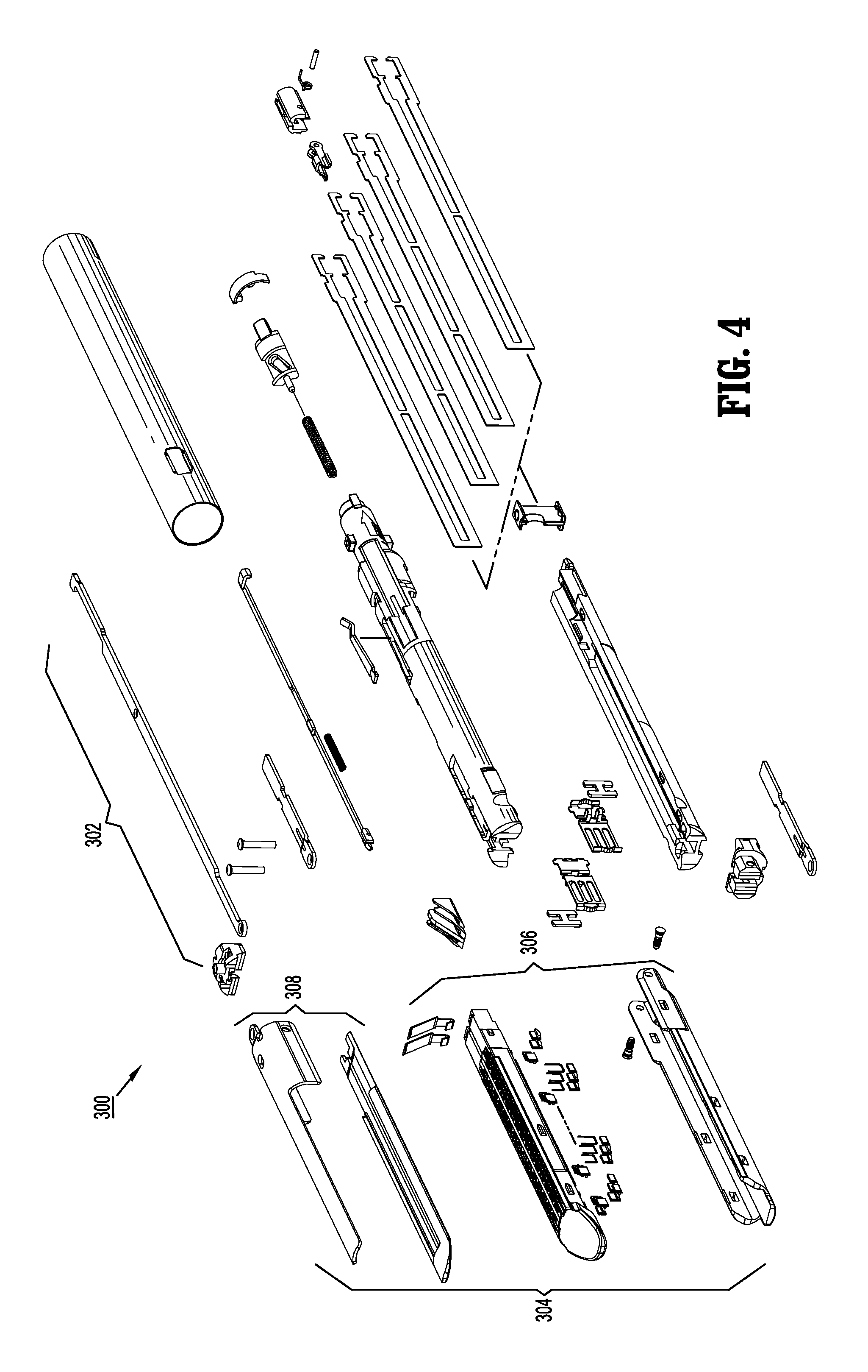
FIG. 4 is a perspective view, with parts separated, of a surgical attachment of the system shown in FIGS. 1A and 1B.
DETAILED DESCRIPTION OF EMBODIMENTS
Embodiments of the presently disclosed surgical devices, adapter assemblies, and surgical attachments are described in detail with reference to the drawings, in which like reference numerals designate identical or corresponding elements in each of the several views. As used herein the term "distal" refers to that portion of the adapter assembly or surgical device, or component thereof, farther from the user, while the term "proximal" refers to that portion of the adapter assembly or surgical device, or component thereof, closer to the user.
A surgical device, in accordance with an embodiment of the present disclosure, is generally designated as 100, and is in the form of a powered hand held electromechanical surgical device configured for selective attachment thereto of a plurality of different end effectors. The end effectors may be any one of various surgical attachments including, but not limited to a surgical stapler, a surgical cutter, a surgical stapler-cutter, a linear surgical stapler, a linear surgical stapler-cutter, a circular surgical stapler, a circular surgical stapler-cutter, a surgical clip applier, a surgical clip ligator, a surgical clamping device, a vessel expanding device, a lumen expanding device, a scalpel, a fluid delivery device or any other type of surgical instrument. Each of the surgical attachments is configured for actuation and manipulation by the powered hand held electromechanical surgical device.
As illustrated in FIGS. 1A and 1B, a surgical system is provided, such as, for example, an electromechanical surgical system 10. System 10 includes hand-held electromechanical surgical device 100 configured for selective connection with an adapter assembly 200, and, in turn, adapter assembly 200 is configured for selective connection with a surgical attachment 300 (e.g., an end effector, multiple- or single-use loading unit, see FIG. 4) that is configured to perform at least one function. Surgical device 100 is configured and adapted to actuate surgical attachment 300. Adapter assembly 200 is connectable with surgical device 100 in at least a first connection orientation, as shown, for example, in FIG. 1A, and a second connection orientation, as shown, for example, in FIG. 1B, as described herein.
As illustrated in FIGS. 1A and 1B, surgical device 100 includes a housing, such as, for example, a handle housing 102 including a circuit board (not shown) and a drive mechanism (not shown) situated therein. The circuit board is configured to control the various operations of surgical device 100. Handle housing 102 defines a cavity therein (not shown) for selective removable receipt of a rechargeable battery (not shown) therein. The battery is configured to supply power to any of the electrical components of surgical device 100 including electric motors used to drive the operation of surgical attachment 300.
Handle housing 102 includes an upper housing portion 102a which houses various components of surgical device 100, and a lower hand grip portion 102b extending from upper housing portion 102a. Lower hand grip portion 102b may be disposed distally of a proximal-most end of upper housing portion 102a. In some embodiments, lower hand grip portion 102b has various surface features, such as, for example, knurled, smooth, rough, and/or textured to enhance a practitioner's gripping of lower hand grip portion 102b.
Handle housing 102 provides a housing in which a drive mechanism is situated. The drive mechanism is configured to drive shafts and/or gear components in order to perform the various operations of surgical device 100. In particular, the drive mechanism is configured to drive shafts and/or gear components in order to selectively move a tool assembly 304 of surgical attachment 300 (see FIG. 4) relative to a proximal body portion 302 of surgical attachment 300, to rotate surgical attachment 300 about a longitudinal axis relative to handle housing 102, to move/approximate an anvil assembly 306 and a cartridge assembly 308 of surgical attachment 300 relative to one another, and/or to fire a stapling and cutting cartridge within cartridge assembly 308 of surgical attachment 300.
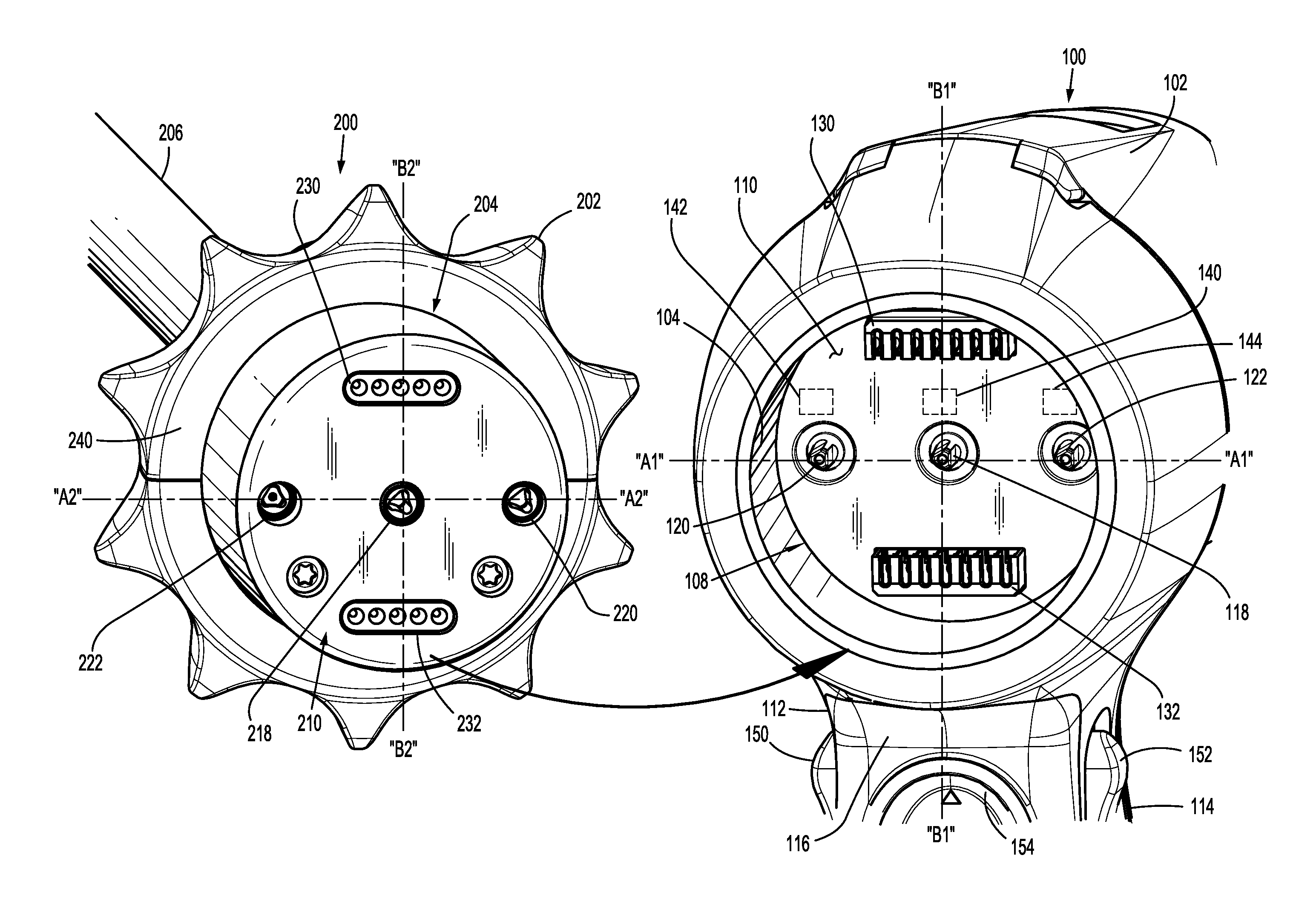
As illustrated in FIG. 2, handle housing 102 includes a recess 104 formed in a surface thereof that defines a female mating part, such as, for example, a connection portion 108 configured to accept a correspondingly shaped male mating part 210 of adapter assembly 200 in various orientations, such as, for example, a first connection orientation and a second connection orientation. Connection portion 108 includes a planar face 110 and a substantially circular configuration. In some embodiments, connection portion 108 has alternative configurations, such as, for example, oval, oblong, triangular, square, rectangular, hexagonal, polygonal, or star-shaped, configured for mating engagement with correspondingly shaped male mating part 210 of adapter assembly 110.
Connection portion 108 houses three rotatable drive connectors 118, 120, 122 protruding from planar face 110. Rotatable drive connectors 118, 120, 122 are arranged in a common plane or line "A1-A1" with one another such that rotatable drive connectors 118, 120, 122 are aligned in a symmetrical configuration. Additionally, in the embodiment illustrated in FIGS. 2 and 3, it is contemplated that a second and a third drive connector 120, 122 may be spaced an equal distance from a first drive connector 118.
In one embodiment, rotatable drive connectors 118, 120, 122 may be arranged in a circular pattern. It is contemplated that rotatable drive connectors 118, 120, 122 may be arranged in various configurations, such as, for example, those alternatives described herein above or below. In some embodiments, connection portion 108 may house more than three rotatable drive connectors.
Planar face 110 of connection portion 108 further includes a first electrical connector, such as, for example, a first electrical plug/receptacle 130 and a second electrical connector, such as, for example, a second electrical plug/receptacle 132, each being disposed on opposite sides of the plane "A1-A1" intersecting rotatable drive shafts 118, 120, 122. Electrical plugs/receptacles 130, 132 are configured for electrical connection with either a first set of electrical contact pins 230 or a second set of electrical contact pins 232 of adapter assembly 200 depending on an orientation of adapter assembly 200 relative to surgical device 100. Contact pin sets 230, 232 may be supported on a circuit board (not shown), as will be described in greater detail herein below. Electrical plugs 130, 132 may be symmetrically spaced about first drive connector 118 along a plane "B1-B1." It is contemplated that connection portion 108 may include more than two electrical plugs. In some embodiments, connection portion 108 may include a plurality of electrical plugs/receptacles circumferentially disposed about rotatable drive connectors 118, 120, 122.
Surgical device 100 includes a first motor 140, a second motor 142 and a third motor 144 (e.g., electric motors), shown in phantom in FIG. 2. Motors 140, 142, 144 are disposed within handle housing 102 for driving movement of surgical attachment 300 via adapter assembly 200 that is connected to rotatable drive connectors 118, 120, 122. Motors 140, 142, 144 are connected to rotatable drive connectors 118, 120, 122, respectively, so that each motor 140, 142, 144 separately drives the rotation of each rotatable drive connector 118, 120, 122.
As illustrated in FIGS. 1A, 1B and 2, handle housing 102 supports a plurality of actuators, such as, for example, finger-actuated user input buttons each being configured to actuate a different function to be performed by surgical attachment 300. The actuators are in operative mechanical and/or electrical communication with motors 140, 142, 144 such that when a user actuates one of the actuators, a respective one of motors 118, 120, 122 is activated, and in turn actuates a function performed by surgical attachment 300 that is assigned to that particular actuator being actuated.
A first actuator, such as, for example, a first user input button 150 is disposed on a first lateral side 112 of lower hand grip portion 102b and a second actuator, such as, for example, a second user input button 152 is disposed on a second lateral side 114 of lower hand grip portion 102b, opposite first lateral side 112. A third actuator, such as, for example, a third user input button 154 is disposed on a distal side 116 of lower hand grip portion 102b. First user input button 150 is configured to actuate a first function, such as, for example, clamping and unclamping of surgical attachment 300. Second user input button 152 is configured to actuate a second function, such as, for example, rotating of surgical attachment 300. Third user input button 154 is configured to actuate a third function, such as, for example, a closing/opening and/or stapling/cutting function of surgical attachment 300. In some embodiments, user input buttons 150, 152, 154 are assigned to actuate various functions to be carried out by various surgical attachments. It is contemplated that the actuators can be variously configured, such as, for example, as switches, rockers, flaps, latches or levers. In some embodiments, surgical device 100 includes a plurality of actuators situated in various portions of handle housing 102.
When adapter assembly 200 is mated to surgical device 100, in a first connection orientation, each of rotatable drive connectors 118, 120, 122 of surgical device 100 couples with a corresponding drive shaft 218, 220, 222 of adapter assembly 200, as described herein. In this regard, the interface between corresponding first drive connector 118 and first drive shaft 218, the interface between corresponding second drive connector 120 and second drive shaft 220, and the interface between corresponding third drive connector 122 and third drive shaft 222 are keyed such that rotation of each of drive connectors 118, 120, 122 of surgical device 100 causes a corresponding rotation of the corresponding drive shafts 218, 220, 222 of adapter assembly 200.
The mating of drive connectors 118, 120, 122 of surgical device 100 with drive shafts 218, 220, 222 of adapter assembly 200 allows rotational forces to be independently transmitted via each of the three respective connector interfaces. The drive connectors 118, 120, 122 of surgical device 100 are configured to be independently rotated by each respective motor 140, 142, 144 of surgical device 100.
Since each of drive connectors 118, 120, 122 of surgical device 100 has a keyed and/or substantially non-rotatable interface with respective drive shafts 218, 220, 222 of adapter assembly 200, when adapter assembly 200 is coupled to surgical device 100, in a first connection orientation, rotational force(s) are selectively transferred from drive connectors 118, 120, 122 of surgical device 100 to corresponding drive shafts 218, 220, 222 of adapter assembly 200.
The selective rotation of drive connectors 118, 120 and/or 122 of surgical device 100 allows surgical device 100 to selectively actuate different functions of surgical attachment 300. For example, selective and independent rotation of first drive connector 118 of surgical device 100 corresponds to the selective and independent opening and closing of tool assembly 304 of surgical attachment 300, and driving of a stapling/cutting component of tool assembly 304 of surgical attachment 300. As an additional example, the selective and independent rotation of second drive connector 120 of surgical device 100 corresponds to the selective and independent articulation of tool assembly 304 of surgical attachment 300 transverse to longitudinal axis "X-X" (see FIG. 1A). Additionally, for instance, the selective and independent rotation of third drive connector 122 of surgical device 100 corresponds to the selective and independent rotation of surgical attachment 300 about longitudinal axis "X-X" (see FIG. 1A) relative to handle housing 102 of surgical device 100.
Turning to FIGS. 2 and 3, system 10 includes adapter assembly 200 for selectively interconnecting surgical device 100 with surgical attachment 300, as briefly described above. Adapter assembly 200 is in operative communication with motors 140, 142, 144 of surgical device 100 when adapter assembly 200 is coupled to surgical device 100. Adapter assembly 200 functions to transmit rotations of motors 140, 142, 144 to drive the functions to be carried out by surgical attachment 300. Adapter assembly 200 includes an outer knob housing 202 and an outer tube 206 extending from a distal end 242 of knob housing 202. Knob housing 202 and outer tube 206 are configured and dimensioned to house the components of adapter assembly 200. Outer tube 206 is dimensioned for endoscopic insertion. In particular, outer tube 206 is passable through a typical trocar port, cannula or the like. Knob housing 202 is dimensioned to not enter the trocar port, cannula or the like. Knob housing 202 is configured and adapted to connect to a distal end of handle housing 102 of surgical device 100.
Adapter assembly 200 includes a proximal inner housing assembly 204 disposed within knob housing 202. Inner housing assembly 204 defines a proximal end 204a and a distal end 204b. Proximal end 204a includes a mating part, such as, for example, male mating part 210. Male mating part 210 is detachably connectable with connection portion 108 of surgical device 100 such that surgical device 100 and surgical attachment 300 are connectable via adapter assembly 200.
Male mating part 210 is configured to permit coupling of adapter assembly 200 to surgical device 100 in at least a first connection orientation and a second connection orientation. In one embodiment, distal end 242 of inner housing assembly 204 is detachably connectable with a corresponding mating part (not shown) of surgical attachment 100 in a similar manner as adapter assembly 200 is coupled with surgical device 100. Male mating part 210 projects from proximal end 204a of knob housing 202. Male mating part 210 has a substantially circular configuration shaped and configured to fit in connection portion 108 of surgical device 100 such that male mating part 210 and connection portion 108 are connectable in various connection orientations relative to one another.
For example, male mating part 210 of adapter assembly 200 can connect with connection portion 108 of surgical device 100 in a first radial orientation or a second radial orientation relative to connection portion 108. Surgical device 100 and adapter assembly 200 are relatively rotated approximately 180 degrees about longitudinal axis "X-X" to be positioned in either the first or second radial orientations. In some embodiments, male mating part 210 is variously shaped, such as, for example, triangular, oval, square, rectangular, diamond or star-shaped.
Male mating part 210 includes a plurality of mating parts, such as, for example, first drive shaft 218, second drive shaft 220, and third drive shaft 222 rotatably supported in inner housing assembly 204. Drive shafts 218, 220, 222 are arranged in a common plane or line "A2-A2" with one another such that drive shafts 218, 220, 222 are aligned in a symmetrical configuration. Additionally, in the embodiment illustrated in FIGS. 2 and 3, it is contemplated that a second and a third drive shaft 220, 222 may be spaced an equal distance from a first drive shaft 218.
Proximal ends of drive shafts 218, 220, 222 each define a recess configured to matingly engage distal projections of rotatable drive connectors 118, 120, 122 of surgical device 100. As shown in the illustrated embodiment, recesses of drive shafts 218, 220, 222 and distal projections of rotatable drive connectors 118, 120, 122 have non-circular configurations. In some embodiments, various configurations of the recesses and the distal projections are contemplated, such as, for example, triangular, square, rectangular, oval, tapered, oblong, star-shaped, kidney-bean shaped, polygonal and/or non-circular. Each drive shaft 218, 220, 222 functions as a rotation receiving member to receive rotational forces from respective rotatable drive connectors 118, 120, 122 of surgical device 100 during actuation of motors 140, 142, 144.
Drive shafts 218, 220, 222 of adapter assembly 200 are connectable with motors 140, 142, 144, respectively, via rotatable drive connectors 118, 120, 122 of surgical device 100. In the first connection orientation, adapter assembly 200 is engaged to surgical device 100 such that first motor 142 is coupled with second drive shaft 220 of adapter assembly 200 and third motor 144 is coupled with third drive shaft 222 of adapter assembly 200. In the second connection orientation, adapter assembly 200 is engaged to surgical device 100 such that second motor 142 is coupled with third drive shaft 222 of adapter assembly 200 and third motor 144 is coupled with second drive shaft 220 of adapter assembly 200. To move from the first connection orientation to the second connection orientation, adapter assembly 200 can be disconnected from surgical device 100 and rotated approximately 180 degrees along the longitudinal axis "X-X" relative to surgical device 100 and then be reconnected to surgical device 100.
In the illustrated embodiment, in either of the first and second connection orientations, first motor 140 is coupled with first drive shaft 218 of adapter assembly 200 as a result of the straight-lined or planar arrangement of drive shafts 218, 220, 222. However, in alternative embodiments in which drive shafts 218, 220, 222 are arranged in an alternative pattern, for example, a circular pattern, second motor 142 would be coupled with a different drive shaft in each connection orientation.
Adapter assembly 200 is configured to be able to establish or determine the connection orientation with surgical device 100. Male mating part 210 includes electrical contact pin sets 230, 232 connectable with either first electrical plug 130 or second electrical plug 132 of surgical device 100 depending on the connection orientation selected. Electrical contact pin sets 230, 232 are each disposed on opposite sides of the plane "A2-A2" intersecting drive shafts 218, 220, 222 of adapter assembly 200. Electrical contact pin sets 230, 232 may be symmetrically spaced about first drive shaft 218 along a plane "B2-B2." Electrical contact pin sets 230, 232 are capable of determining the connection orientation between surgical device 100 and adapter assembly 200 based on which electrical plug 130, 132 each electrical contact pin set 230, 232 is connected to.
For example, if first and second electrical plugs 130, 132 are connected to first and second electrical contact pin sets 230, 232, respectively, adapter assembly 200 may be preprogrammed to determine that this qualifies as a first connection orientation. If first and second electrical plugs 130, 132 are connected to second and first electrical contact pin sets 232, 230, respectively, adapter assembly 200 may be preprogrammed to determine that this qualifies as a second connection orientation.
Each user input button 150, 152, 154 is assigned to actuate a particular function carried out by surgical attachment 300 depending on the connection orientation determined by adapter assembly 200. Thus, adapter assembly 200 may interchange or reverse the functions actuated by user input buttons 150, 152, 154 of surgical device 100 when the connection orientation of surgical device 100 and adapter assembly 200 moves between the first and second connection orientations. Adapter assembly 200 and/or surgical device 100 may include a processor configured to assign the functions to be actuated by a particular user input button 150, 152, 154 upon adapter assembly 200 recognizing or determining the connection orientation of surgical device 100 and adapter assembly 200.
In some embodiments, when an actuator of surgical device 100 is activated by a user, software checks predefined conditions. If conditions are met, the software controls the motors and delivers mechanical drive to the surgical attachment 300, which can then open, close, rotate, articulate or fire depending on the function of the pressed actuator. The software also provides feedback to the user by turning colored lights on or off in a defined manner to indicate the status of surgical device 100, adapter assembly 200 and/or surgical attachment 300.
As shown in FIG. 4, system 10 further includes surgical attachment 300. In the illustrated embodiment, surgical attachment 300 extends between a proximal body portion 302 connected to outer body 206 of adapter assembly 200 and a distal tool assembly 304. Proximal body portion 302 may have an arcuate configuration, as shown in FIGS. 1A and 1B. It is contemplated that proximal body portion 302 is variously configured, such as, for example, straight, bent, U-shaped, or V-shaped. Surgical attachment 300 is rotatable relative to outer body 206 about longitudinal axis "X-X." Tool assembly 304 includes a cartridge assembly 306 and an anvil assembly 308. Cartridge assembly 306 includes a stapling and cutting cartridge. Cartridge assembly 306 and anvil assembly 308 are pivotable relative to one another to clamp or unclamp material, such as, for example, tissue, therebetween.
Reference may be made to U.S. Patent Publication No. 2009/0314821, filed on Aug. 31, 2009, entitled "TOOL ASSEMBLY FOR A SURGICAL STAPLING DEVICE" for a detailed discussion of the construction and operation of surgical attachment 300, as illustrated in FIGS. 1A, 1B and 4.
It is contemplated that surgical attachment 300 can be something other than the surgical attachment shown in the illustrated embodiment, such as, for example, a surgical stapler, a surgical cutter, a surgical stapler-cutter, a linear surgical stapler, a linear surgical stapler-cutter, a circular surgical stapler, a circular surgical stapler-cutter, a surgical clip applier, a surgical clip ligator, a surgical clamping device, a vessel expanding device, a lumen expanding device, a scalpel, a fluid delivery device or any other type of surgical instrument. Such surgical instruments are described, for example, in U.S. Pat. Nos. 6,315,184; 6,443,973; 6,264,087; 6,348,061; 6,716,233; 6,533,157; 6,491,201; and 6,488,197; each of which is expressly incorporated herein in its entirety by reference thereto.
In operation, proximal body portion 302 of surgical attachment 300 is engaged to a distal end of outer tube 206 of adapter assembly 200 to connect surgical attachment 300 to adapter assembly 200. In one arrangement, male mating part 210 is inserted within connection portion 108 of surgical device 100, while in the first connection orientation, such that rotatable drive connectors 118, 120, 122 of surgical device 100 engage drive shafts 218, 220, 222 of adapter assembly 200, respectively. First and second electrical contact pin sets 230, 232 of adapter assembly 200 engage first and second electrical plugs 130, 132, respectively, such that outer body 206 of surgical attachment 300 is angled upwards relative to surgical device 100, as shown in FIG. 1A. In so doing, adapter assembly 200 is coupled with surgical device 100 in the first connection orientation.
In another arrangement, male mating part 210 is inserted within connection portion 108 of surgical device 100, while in the second connection orientation, such that rotatable drive connectors 118, 120, 122 of surgical device 100 engage drive shafts 218, 222, 220 of adapter assembly 200, respectively. First and second electrical contact pin sets 230, 232 of adapter assembly 200 engage second and first electrical plugs 132, 130, respectively, such that outer body 206 of surgical attachment 300 is angled downwards relative to surgical device 100, as shown in FIG. 1B. In so doing, adapter assembly 200 is coupled with surgical device 100 in the second connection orientation.
First user input button 150 is configured and adapted to actuate a clamping function of surgical attachment 300 and second user input button 152 is configured and adapted to actuate an unclamping function of surgical attachment 300 when adapter assembly 200 establishes, determines, or recognizes that it is coupled with surgical device 100 in the first connection orientation. In the first connection orientation, when user input button 150 is actuated, tool assembly 304 articulates transverse to longitudinal axis "X-X", and when user input button 152 is actuated, surgical attachment 300 rotates about longitudinal axis "X-X" relative to handle housing 102 of surgical device 100.
A practitioner may prefer that user input buttons 150, 152 be in a reversed orientation on lower hand grip portion 102b of handle housing 102, or a particular surgical procedure may require that surgical device 100 and/or surgical attachment 300 be in an inverted position relative to a practitioner's hand, as shown in FIG. 1B. In such instances, it may preferable that the functions actuated by user input buttons 150, 152 be reversed. System 10 can be preprogrammed or reprogrammed so that the functions assigned to user input buttons 150, 152 in the first connection orientation are to be reversed or interchanged when surgical device 100 is coupled with adapter assembly 200 in the second connection orientation.
In use, adapter assembly 200 is disconnected from surgical device 100 and rotated approximately 180 degrees, about the longitudinal axis "X-X," relative to surgical device 100. Male mating part 210 of adapter assembly 200 is then re-inserted within connection portion 108 of surgical device 100 such that first, second and third rotatable drive connectors 118, 120, 122 of surgical device 100 engage first, third and second drive shafts 218, 222, 220 of adapter assembly, respectively. Further, first and second electrical connector pin sets 230, 232 of adapter assembly 200 engage second and first electrical plugs 132, 130, respectively, such that outer body 206 of surgical attachment 300 is oriented in a different orientation relative to surgical device 100, as shown in FIG. 1B. In so doing, adapter assembly 200 is coupled with surgical device 100, in the second connection orientation. Once adapter assembly 200 is re-coupled with surgical device 100, surgical device 100 determines, establishes or recognizes that the adapter assembly 200 is coupled thereto in the second connection orientation.
In the second connection orientation, when user input button 150 is actuated, surgical attachment 300 rotates about longitudinal axis "X-X" relative to handle housing 102 of surgical device 100, and when user input button 152 is actuated, tool assembly 304 articulates transverse to longitudinal axis "X-X", thus reversing the functions actuated by user input buttons 150, 152.
In one embodiment, adapter assembly 200 is configured to provide surgical device 100 with the capability to actuate surgical attachment 300 in a plurality of speed settings depending on the requirements of a particular application. Adapter assembly 200 is connectable with surgical device 100 in a plurality of connection orientations, as described herein. Each orientation of the plurality of orientations corresponds to a different rate of motion of surgical attachment 300 when surgical attachment 300 is actuated. In use, if a practitioner desires to adjust the actuation speed of surgical attachment 300, the connection orientation between adapter assembly 200 and surgical device 100 is changed, in a similar manner described above, such that the adapter assembly 200 changes the speed of actuation of surgical attachment to a speed corresponding to the connection orientation selected.
Any of the components described herein may be fabricated from either metals, plastics, resins, composites or the like taking into consideration strength, durability, wearability, weight, resistance to corrosion, ease of manufacturing, cost of manufacturing, and the like.
It will be understood that various modifications may be made to the embodiments of the presently disclosed adapter assemblies. Therefore, the above description should not be construed as limiting, but merely as exemplifications of embodiments. Those skilled in the art will envision other modifications within the scope and spirit of the present disclosure.
* * * * *
D00000
D00001
D00002
D00003
D00004
D00005
XML
uspto.report is an independent third-party trademark research tool that is not affiliated, endorsed, or sponsored by the United States Patent and Trademark Office (USPTO) or any other governmental organization. The information provided by uspto.report is based on publicly available data at the time of writing and is intended for informational purposes only.
While we strive to provide accurate and up-to-date information, we do not guarantee the accuracy, completeness, reliability, or suitability of the information displayed on this site. The use of this site is at your own risk. Any reliance you place on such information is therefore strictly at your own risk.
All official trademark data, including owner information, should be verified by visiting the official USPTO website at www.uspto.gov. This site is not intended to replace professional legal advice and should not be used as a substitute for consulting with a legal professional who is knowledgeable about trademark law.