Manipulating surface topology of BMG feedstock
Prest , et al.
U.S. patent number 10,233,525 [Application Number 14/740,182] was granted by the patent office on 2019-03-19 for manipulating surface topology of bmg feedstock. This patent grant is currently assigned to APPLE INC.. The grantee listed for this patent is Apple Inc.. Invention is credited to Quoc Tran Pham, Joseph C. Poole, Christopher D. Prest, Joseph Stevick, Theodore Andrew Waniuk.

| United States Patent | 10,233,525 |
| Prest , et al. | March 19, 2019 |
Manipulating surface topology of BMG feedstock
Abstract
Described herein is a feedstock comprising BMG. The feedstock has a surface with an average roughness of at least 200 microns. Also described herein is a feedstock comprising BMG. The feedstock, when supported on a support during a melting process of the feedstock, has a contact area between the feedstock and the support up to 50% of a total area of the support. These feedstocks can be made by molding ingots of BMG into a mole with surface patterns, enclosing one or more cores into a sheath with a roughened surface, chemical etching, laser ablating, machining, grinding, sandblasting, or shot peening. The feedstocks can be used as starting materials in an injection molding process.
| Inventors: | Prest; Christopher D. (Cupertino, CA), Poole; Joseph C. (Cupertino, CA), Stevick; Joseph (Dana Point, CA), Pham; Quoc Tran (Dana Point, CA), Waniuk; Theodore Andrew (Cupertino, CA) | ||||||||||
|---|---|---|---|---|---|---|---|---|---|---|---|
| Applicant: |
|
||||||||||
| Assignee: | APPLE INC. (Cupertino,
CA) |
||||||||||
| Family ID: | 49580309 | ||||||||||
| Appl. No.: | 14/740,182 | ||||||||||
| Filed: | June 15, 2015 |
Prior Publication Data
| Document Identifier | Publication Date | |
|---|---|---|
| US 20160102391 A1 | Apr 14, 2016 | |
Related U.S. Patent Documents
| Application Number | Filing Date | Patent Number | Issue Date | ||
|---|---|---|---|---|---|
| 13472056 | May 15, 2012 | 9056353 | |||
| Current U.S. Class: | 1/1 |
| Current CPC Class: | C22C 1/02 (20130101); C22C 45/10 (20130101); C22C 45/001 (20130101); C22C 1/002 (20130101); C22C 33/003 (20130101); B22D 41/01 (20130101); B22D 17/00 (20130101); B22D 25/06 (20130101); C22C 30/00 (20130101); C22C 45/02 (20130101); C22C 45/003 (20130101); C22C 45/00 (20130101) |
| Current International Class: | B32B 3/24 (20060101); C22C 1/00 (20060101); C22C 33/00 (20060101); C22C 45/02 (20060101); C22C 30/00 (20060101); C22C 45/00 (20060101); B22D 41/01 (20060101); C22C 1/02 (20060101); B22D 25/06 (20060101); B22D 17/00 (20060101); C22C 45/10 (20060101) |
| Field of Search: | ;148/403 ;164/113,48 ;428/596,599,604,603,612 |
References Cited [Referenced By]
U.S. Patent Documents
| 5288344 | February 1994 | Peker et al. |
| 5368659 | November 1994 | Peker et al. |
| 5618359 | April 1997 | Lin et al. |
| 5711363 | January 1998 | Scruggs et al. |
| 5735975 | April 1998 | Lin et al. |
| 6325868 | December 2001 | Kim et al. |
| 7575040 | August 2009 | Johnson |
| 7618499 | November 2009 | Johnson et al. |
| 7806997 | October 2010 | Demetriou et al. |
| 8326227 | August 2012 | Batchelder et al. |
| 8480864 | July 2013 | Farmer et al. |
| 8529712 | September 2013 | Demetriou et al. |
| 9056353 | June 2015 | Prest et al. |
| 2011/0162795 | July 2011 | Pham |
| 2014/0199560 | July 2014 | Gong |
| 2014/0293384 | October 2014 | O'keeffe |
| 102430745 | May 2012 | CN | |||
| 2001303218 | Oct 2001 | JP | |||
Other References
|
Electropolishing RA & RMS, May 27, 2012, Harrison Electropolishing L.P. (Year: 2012). cited by examiner . Dow et al., Mesoscale and Microscale Manufacturing Processes: Challenges for Materials, Fabrication and Metrology, 2003, Precision Engineering Center North Carolina State University (Year: 2003). cited by examiner . Microscale definition, yourdictonary.com, 2014 (Year: 2014). cited by examiner . Inoue et al., "Bulk amorphous alloys with high mechanical strength and good soft magnetic properties in Fe-TM-B (TM=IV-VIII group transition metal) system," Appl. Phys. Lett, 1997, vol. 71, No. 4, pp. 464-466. cited by applicant . Shen et al., "Bulk Glassy Co.sub.43FE.sub.20TA.sub.5.5B.sub.31.5 Alloy with High Glass-Forming Ability and Good Soft Magnetic Properties," Materials Transactions, 2001 The Japan Institute of Metals, vol. 42, No. 10 p. 2136-2139. cited by applicant. |
Primary Examiner: Sample; David
Assistant Examiner: Omori; Mary I
Attorney, Agent or Firm: Dorsey & Whitney LLP
Parent Case Text
This application is a continuation of U.S. patent application Ser. No. 13/472,056, entitled "Manipulating Surface Topology of BMG Feedstock," filed May 15, 2012, which is incorporated by reference in its entirety as if fully disclosed herein.
Claims
We claim:
1. A bulk-solidifying amorphous alloy feedstock comprising a body including an outer surface having recesses distributed around the body and having depths between about 2000 microns and about 5000 microns, thereby defining a roughness parameter between about 2000 microns and about 5000 microns.
2. The bulk-solidifying amorphous alloy feedstock of claim 1, wherein the recesses are uniformly distributed around the body.
3. The bulk-solidifying amorphous alloy feedstock of claim 2, wherein the recesses are separate from each other.
4. The bulk-solidifying amorphous alloy feedstock of claim 1, wherein the outer surface forms a contact area with a support surface of a melting vessel that is less than 50% of an interface area between the support surface and the feedstock.
5. The bulk-solidifying amorphous alloy feedstock of claim 1, wherein the outer surface forms a contact area with a support surface of a melting vessel that is less than 25% of an interface area between the support surface and the feedstock.
6. A bulk-solidifying amorphous alloy ingot having a cylindrical shape and comprising an outer surface having a roughness between about 2000 microns and about 5000 microns and defining grooves positioned around a circumference of the ingot and parallel to a longitudinal axis of the ingot.
7. The bulk-solidifying amorphous alloy ingot of claim 6, wherein a depth of the grooves is from 2000 microns to 5000 microns.
8. The bulk-solidifying amorphous alloy ingot of claim 6, wherein the grooves are uniformly distributed around a circumference of the ingot.
9. The bulk-solidifying amorphous alloy ingot of claim 6, wherein the outer surface forms a contact area with a support surface of a melting vessel that is less than 10% of an interface area between the support surface and the ingot.
10. The bulk-solidifying amorphous alloy ingot of claim 6, wherein the outer surface exhibits less heat loss from the ingot to a melting vessel during heating of the ingot as compared to a reference surface having a lower surface roughness.
11. A bulk-solidifying amorphous alloy feedstock, comprising: a core; and a sheath at least partially surrounding the core and defining an outer surface of the feedstock having a surface roughness of at least 2000 microns.
12. The bulk-solidifying amorphous alloy feedstock of claim 11, wherein the sheath and the core are formed from a same material.
13. The bulk-solidifying amorphous alloy feedstock of claim 11, wherein: the core is a first core; and the bulk-solidifying amorphous alloy feedstock further comprises a second core.
14. The bulk-solidifying amorphous alloy feedstock of claim 13, wherein the first core and the second core comprise different materials.
15. The bulk-solidifying amorphous alloy feedstock of claim 11, wherein: the surface roughness is less than about 5000 microns.
16. The bulk-solidifying amorphous alloy feedstock of claim 11, wherein the outer surface of the feedstock comprises recesses.
Description
BACKGROUND
A large portion of the metallic alloys in use today are processed by solidification casting, at least initially. The metallic alloy is melted and cast into a metal or ceramic mold, where it solidifies. The mold is stripped away, and the cast metallic piece is ready for use or further processing. The as-cast structure of most materials produced during solidification and cooling depends upon the cooling rate. There is no general rule for the nature of the variation, but for the most part the structure changes only gradually with changes in cooling rate. On the other hand, for the bulk-solidifying amorphous alloys the change between the amorphous state produced by relatively rapid cooling and the crystalline state produced by relatively slower cooling is one of kind rather than degree--the two states have distinct properties.
Bulk-solidifying amorphous alloys, or bulk metallic glasses ("BMG"), are a recently developed class of metallic materials. These alloys may be solidified and cooled at relatively slow rates, and they retain the amorphous, non-crystalline (i.e., glassy) state at room temperature. This amorphous state can be highly advantageous for certain applications. If the cooling rate is not sufficiently high, crystals may form inside the alloy during cooling, so that the benefits of the amorphous state are partially or completely lost. For example, one risk with the creation of bulk amorphous alloy parts is partial crystallization due to either slow cooling or impurities in the raw material.
Bulk-solidifying amorphous alloys have been made in a variety of metallic systems. They are generally prepared by quenching from above the melting temperature to the ambient temperature. Generally, high cooling rates such as one on the order of 10.sup.5.degree. C./sec, are needed to achieve an amorphous structure. The lowest rate by which a bulk solidifying alloy can be cooled to avoid crystallization, thereby achieving and maintaining the amorphous structure during cooling, is referred to as the "critical cooling rate" for the alloy. In order to achieve a cooling rate higher than the critical cooling rate, heat has to be extracted from the sample. Thus, the thickness of articles made from amorphous alloys often becomes a limiting dimension, which is generally referred to as the "critical (casting) thickness." A critical thickness of an amorphous alloy can be obtained by heat-flow calculations, taking into account the critical cooling rate.
Until the early nineties, the processability of amorphous alloys was quite limited, and amorphous alloys were readily available only in powder form or in very thin foils or strips with a critical thickness of less than 100 micrometers. A class of amorphous alloys based mostly on Zr and Ti alloy systems was developed in the nineties, and since then more amorphous alloy systems based on different elements have been developed. These families of alloys have much lower critical cooling rates of less than 10.sup.3.degree. C./sec, and thus they have much larger critical casting thicknesses than their previous counterparts. However, little has been shown regarding how to utilize and/or shape these alloy systems into structural components, such as those in consumer electronic devices. In particular, pre-existing forming or processing methods often result in high product cost when it comes to high aspect ratio products (e.g., thin sheets) or three-dimensional hollow products. Moreover, the pre-existing methods can often suffer the drawbacks of producing products that lose many of the desirable mechanical properties as observed in an amorphous alloy.
SUMMARY
Described herein is a feedstock comprising BMG. The feedstock has a surface with an average roughness of at least 200 microns.
Also described herein is a feedstock comprising BMG. The feedstock, when supported on a support during a melting process of the feedstock, has a contact area between the feedstock and the support up to 90% of a total area of the support.
These feedstocks can be made by molding ingots of BMG into a mole with surface patterns, enclosing one or more cores into a sheath with a roughened surface, chemical etching, laser ablating, machining, grinding, sandblasting, or shot peening.
The feedstocks can be used as starting materials in an injection molding process.
BRIEF DESCRIPTION OF FIGURES
FIG. 1 provides a temperature-viscosity diagram of an exemplary bulk solidifying amorphous alloy.
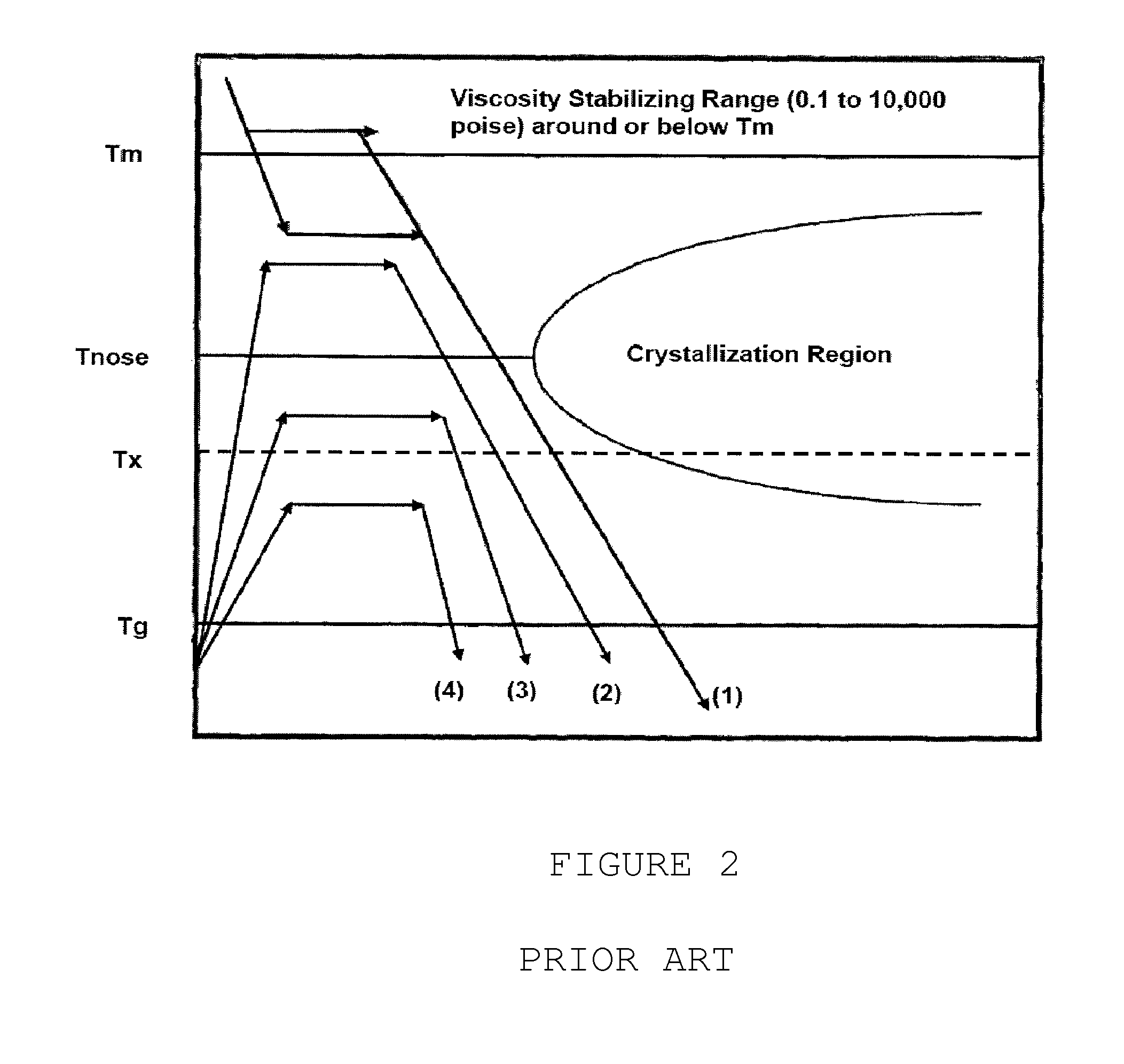
FIG. 2 provides a schematic of a time-temperature-transformation (T) diagram for an exemplary bulk solidifying amorphous alloy.
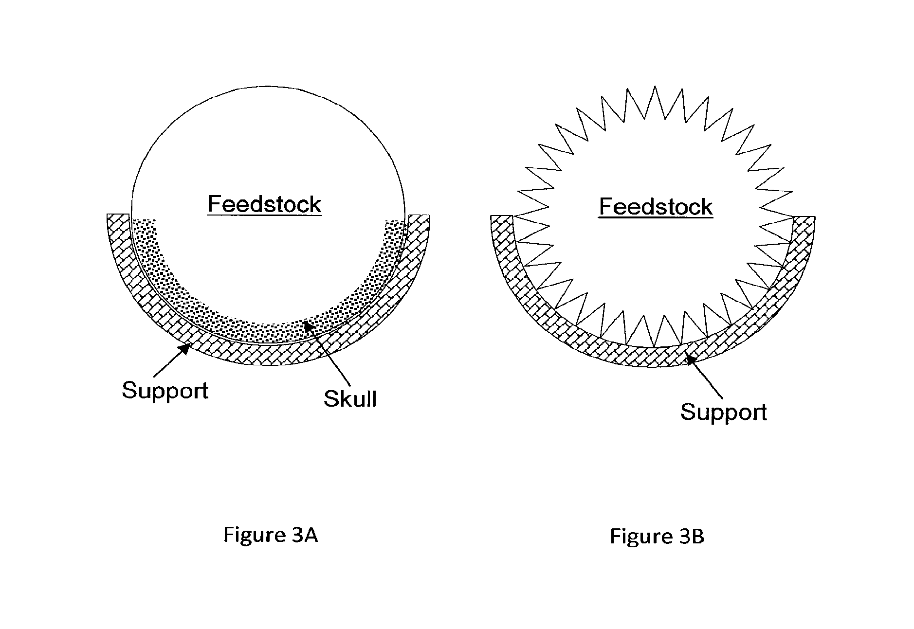
FIG. 3A shows an exemplary induction heating process.
FIG. 3B shows an exemplary induction heating process according to an embodiment.
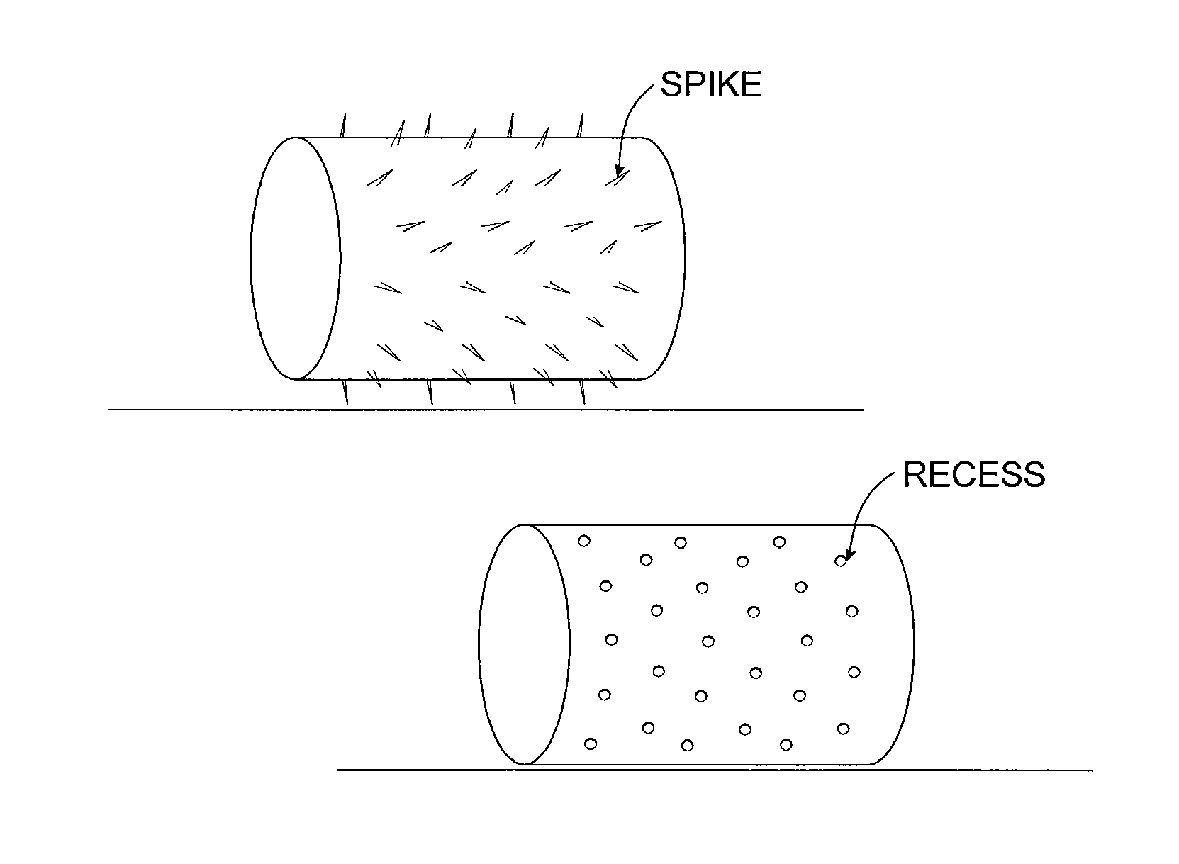
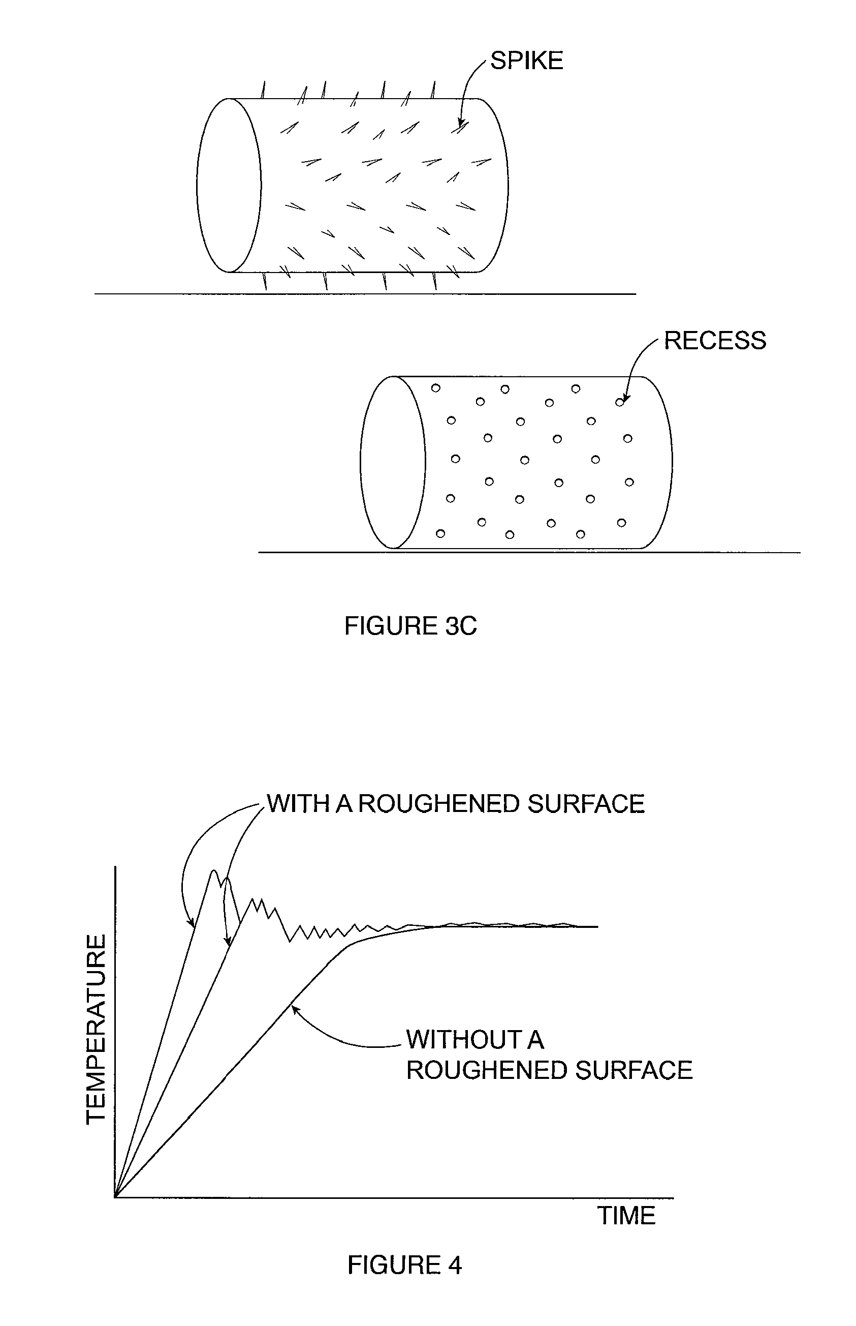
FIG. 3C shows exemplary feedstock comprising a roughened surface having spikes and exemplary feedstock comprising a roughened surface having recesses.
FIG. 4 shows the effect of the roughened surface of the feedstock on the heating rate of the feedstock.
DETAILED DESCRIPTION
All publications, patents, and patent applications cited in this Specification are hereby incorporated by reference in their entirety.
The articles "a" and "an" are used herein to refer to one or to more than one (i.e., to at least one) of the grammatical object of the article. By way of example, "a polymer resin" means one polymer resin or more than one polymer resin. Any ranges cited herein are inclusive. The terms "substantially" and "about" used throughout this Specification are used to describe and account for small fluctuations. For example, they can refer to less than or equal to .+-.5%, such as less than or equal to .+-.2%, such as less than or equal to .+-.1%, such as less than or equal to .+-.0.5%, such as less than or equal to .+-.0.2%, such as less than or equal to .+-.0.1%, such as less than or equal to .+-.0.05%.
Bulk-solidifying amorphous alloys, or bulk metallic glasses ("BMG"), are a recently developed class of metallic materials. These alloys may be solidified and cooled at relatively slow rates, and they retain the amorphous, non-crystalline (i.e., glassy) state at room temperature. Amorphous alloys have many superior properties than their crystalline counterparts. However, if the cooling rate is not sufficiently high, crystals may form inside the alloy during cooling, so that the benefits of the amorphous state can be lost. For example, one challenge with the fabrication of bulk amorphous alloy parts is partial crystallization of the parts due to either slow cooling or impurities in the raw alloy material. As a high degree of amorphicity (and, conversely, a low degree of crystallinity) is desirable in BMG parts, there is a need to develop methods for casting BMG parts having controlled amount of amorphicity.
FIG. 1 (obtained from U.S. Pat. No. 7,575,040) shows a viscosity-temperature graph of an exemplary bulk solidifying amorphous alloy, from the VIT-001 series of Zr--Ti--Ni--Cu--Be family manufactured by Liquidmetal Technology. It should be noted that there is no clear liquid/solid transformation for a bulk solidifying amorphous metal during the formation of an amorphous solid. The molten alloy becomes more and more viscous with increasing undercooling until it approaches solid form around the glass transition temperature. Accordingly, the temperature of solidification front for bulk solidifying amorphous alloys can be around glass transition temperature, where the alloy will practically act as a solid for the purposes of pulling out the quenched amorphous sheet product.
FIG. 2 (obtained from U.S. Pat. No. 7,575,040) shows the time-temperature-transformation (TTT) cooling curve of an exemplary bulk solidifying amorphous alloy, or TTT diagram. Bulk-solidifying amorphous metals do not experience a liquid/solid crystallization transformation upon cooling, as with conventional metals. Instead, the highly fluid, non crystalline form of the metal found at high temperatures (near a "melting temperature" Tm) becomes more viscous as the temperature is reduced (near to the glass transition temperature Tg), eventually taking on the outward physical properties of a conventional solid.
Even though there is no liquid/crystallization transformation for a bulk solidifying amorphous metal, a "melting temperature" Tm may be defined as the thermodynamic liquidus temperature of the corresponding crystalline phase. Under this regime, the viscosity of bulk-solidifying amorphous alloys at the melting temperature could lie in the range of about 0.1 poise to about 10,000 poise, and even sometimes under 0.01 poise. A lower viscosity at the "melting temperature" would provide faster and complete filling of intricate portions of the shell/mold with a bulk solidifying amorphous metal for forming the BMG parts.
Furthermore, the cooling rate of the molten metal to form a BMG part has to such that the time-temperature profile during cooling does not traverse through the nose-shaped region bounding the crystallized region in the TTT diagram of FIG. 2. In FIG. 2, Tnose is the critical crystallization temperature Tx where crystallization is most rapid and occurs in the shortest time scale.
The supercooled liquid region, the temperature region between Tg and Tx is a manifestation of the extraordinary stability against crystallization of bulk solidification alloys. In this temperature region the bulk solidifying alloy can exist as a high viscous liquid. The viscosity of the bulk solidifying alloy in the supercooled liquid region can vary between 10.sup.12 Pa s at the glass transition temperature down to 10.sup.5 Pa s at the crystallization temperature, the high temperature limit of the supercooled liquid region. Liquids with such viscosities can undergo substantial plastic strain under an applied pressure. The embodiments herein make use of the large plastic formability in the supercooled liquid region as a forming and separating method.
One needs to clarify something about Tx. Technically, the nose-shaped curve shown in the TTT diagram describes Tx as a function of temperature and time. Thus, regardless of the trajectory that one takes while heating or cooling a metal alloy, when one hits the TTT curve, one has reached Tx. In FIG. 2, Tx is shown as a dashed line as Tx can vary from close to Tm to close to Tg.
The schematic TTT diagram of FIG. 2 shows processing methods of die casting from at or above Tm to below Tg without the time-temperature trajectory (shown as (1) as an example trajectory) hitting the TTT curve. During die casting, the forming takes place substeantially simultaneously with fast cooling to avoid the trajectory hitting the TTT curve. The procssing methods for superplastic forming (SPF) from at or below Tg to below Tm without the time-temperature trajectory (shown as (2), (3) and (4) as example trajectories) hitting the TTT curve. In SPF, the amorphous BMG is reheated into the supercooled liquid region where the available processing window could be much larger than die casting, resulting in better controllability of the process. The SPF process does not require fast cooling to avoid crystallization during cooling. Also, as shown by example trajectories (2), (3) and (4), the SPF can be carried out with the highest temperature during SPF being above Tnose or below Tnose, up to about Tm. If one heats up a piece of amorphous alloy but manages to avoid hitting the TTT curve, you have heated "between Tg and Tm", but one would have not reached Tx.
Typical differential scanning calorimeter (DSC) heating curves of bulk-solidifying amorphous alloys taken at a heating rate of 20 C/min describe, for the most part, a particular trajectory across the TTT data where one would likely see a Tg at a certain temperature, a Tx when the DSC heating ramp crosses the TTT crystallization onset, and eventually melting peaks when the same trajectory crosses the temperature range for melting. If one heats a bulk-solidifying amorphous alloy at a rapid heating rate as shown by the ramp up portion of trajectories (2), (3) and (4) in FIG. 2, then one could avoid the TTT curve entirely, and the DSC data would show a glass transition but no Tx upon heating. Another way to think about it is trajectories (2), (3) and (4) can fall anywhere in temperature between the nose of the TTT curve (and even above it) and the Tg line, as long as it does not hit the crystallization curve. That just means that the horizontal plateau in trajectories might get much shorter as one increases the processing temperature.
Phase
The term "phase" herein can refer to one that can be found in a thermodynamic phase diagram. A phase is a region of space (e.g., a thermodynamic system) throughout which all physical properties of a material are essentially uniform. Examples of physical properties include density, index of refraction, chemical composition and lattice periodicity. A simple description of a phase is a region of material that is chemically uniform, physically distinct, and/or mechanically separable. For example, in a system consisting of ice and water in a glass jar, the ice cubes are one phase, the water is a second phase, and the humid air over the water is a third phase. The glass of the jar is another separate phase. A phase can refer to a solid solution, which can be a binary, tertiary, quaternary, or more, solution, or a compound, such as an intermetallic compound. As another example, an amorphous phase is distinct from a crystalline phase.
Metal, Transition Metal, and Non-Metal
The term "metal" refers to an electropositive chemical element. The term "element" in this Specification refers generally to an element that can be found in a Periodic Table. Physically, a metal atom in the ground state contains a partially filled band with an empty state close to an occupied state. The term "transition metal" is any of the metallic elements within Groups 3 to 12 in the Periodic Table that have an incomplete inner electron shell and that serve as transitional links between the most and the least electropositive in a series of elements. Transition metals are characterized by multiple valences, colored compounds, and the ability to form stable complex ions. The term "nonmetal" refers to a chemical element that does not have the capacity to lose electrons and form a positive ion.
Depending on the application, any suitable nonmetal elements, or their combinations, can be used. The alloy (or "alloy composition") can comprise multiple nonmetal elements, such as at least two, at least three, at least four, or more, nonmetal elements. A nonmetal element can be any element that is found in Groups 13-17 in the Periodic Table. For example, a nonmetal element can be any one of F, Cl, Br, I, At, O, S, Se, Te, Po, N, P, As, Sb, Bi, C, Si, Ge, Sn, Pb, and B. Occasionally, a nonmetal element can also refer to certain metalloids (e.g., B, Si, Ge, As, Sb, Te, and Po) in Groups 13-17. In one embodiment, the nonmetal elements can include B, Si, C, P, or combinations thereof. Accordingly, for example, the alloy can comprise a boride, a carbide, or both.
A transition metal element can be any of scandium, titanium, vanadium, chromium, manganese, iron, cobalt, nickel, copper, zinc, yttrium, zirconium, niobium, molybdenum, technetium, ruthenium, rhodium, palladium, silver, cadmium, hafnium, tantalum, tungsten, rhenium, osmium, iridium, platinum, gold, mercury, rutherfordium, dubnium, seaborgium, bohrium, hassium, meitnerium, ununnilium, unununium, and ununbium. In one embodiment, a BMG containing a transition metal element can have at least one of Sc, Y, La, Ac, Ti, Zr, Hf, V, Nb, Ta, Cr, Mo, W, Mn, Tc, Re, Fe, Ru, Os, Co, Rh, Ir, Ni, Pd, Pt, Cu, Ag, Au, Zn, Cd, and Hg. Depending on the application, any suitable transitional metal elements, or their combinations, can be used. The alloy composition can comprise multiple transitional metal elements, such as at least two, at least three, at least four, or more, transitional metal elements.
The presently described alloy or alloy "sample" or "specimen" alloy can have any shape or size. For example, the alloy can have a shape of a particulate, which can have a shape such as spherical, ellipsoid, wire-like, rod-like, sheet-like, flake-like, or an irregular shape. The particulate can have any size. For example, it can have an average diameter of between about 1 micron and about 100 microns, such as between about 5 microns and about 80 microns, such as between about 10 microns and about 60 microns, such as between about 15 microns and about 50 microns, such as between about 15 microns and about 45 microns, such as between about 20 microns and about 40 microns, such as between about 25 microns and about 35 microns. For example, in one embodiment, the average diameter of the particulate is between about 25 microns and about 44 microns. In some embodiments, smaller particulates, such as those in the nanometer range, or larger particulates, such as those bigger than 100 microns, can be used.
The alloy sample or specimen can also be of a much larger dimension. For example, it can be a bulk structural component, such as an ingot, housing/casing of an electronic device or even a portion of a structural component that has dimensions in the millimeter, centimeter, or meter range.
Solid Solution
The term "solid solution" refers to a solid form of a solution. The term "solution" refers to a mixture of two or more substances, which may be solids, liquids, gases, or a combination of these. The mixture can be homogeneous or heterogeneous. The term "mixture" is a composition of two or more substances that are combined with each other and are generally capable of being separated. Generally, the two or more substances are not chemically combined with each other.
Alloy
In some embodiments, the alloy composition described herein can be fully alloyed. In one embodiment, an "alloy" refers to a homogeneous mixture or solid solution of two or more metals, the atoms of one replacing or occupying interstitial positions between the atoms of the other; for example, brass is an alloy of zinc and copper. An alloy, in contrast to a composite, can refer to a partial or complete solid solution of one or more elements in a metal matrix, such as one or more compounds in a metallic matrix. The term alloy herein can refer to both a complete solid solution alloy that can give single solid phase microstructure and a partial solution that can give two or more phases. An alloy composition described herein can refer to one comprising an alloy or one comprising an alloy-containing composite.
Thus, a fully alloyed alloy can have a homogenous distribution of the constituents, be it a solid solution phase, a compound phase, or both. The term "fully alloyed" used herein can account for minor variations within the error tolerance. For example, it can refer to at least 90% alloyed, such as at least 95% alloyed, such as at least 99% alloyed, such as at least 99.5% alloyed, such as at least 99.9% alloyed. The percentage herein can refer to either volume percent or weight percentage, depending on the context. These percentages can be balanced by impurities, which can be in terms of composition or phases that are not a part of the alloy.
Amorphous or Non-Crystalline Solid
An "amorphous" or "non-crystalline solid" is a solid that lacks lattice periodicity, which is characteristic of a crystal. As used herein, an "amorphous solid" includes "glass" which is an amorphous solid that softens and transforms into a liquid-like state upon heating through the glass transition. Generally, amorphous materials lack the long-range order characteristic of a crystal, though they can possess some short-range order at the atomic length scale due to the nature of chemical bonding. The distinction between amorphous solids and crystalline solids can be made based on lattice periodicity as determined by structural characterization techniques such as x-ray diffraction and transmission electron microscopy.
The terms "order" and "disorder" designate the presence or absence of some symmetry or correlation in a many-particle system. The terms "long-range order" and "short-range order" distinguish order in materials based on length scales.
The strictest form of order in a solid is lattice periodicity: a certain pattern (the arrangement of atoms in a unit cell) is repeated again and again to form a translationally invariant tiling of space. This is the defining property of a crystal. Possible symmetries have been classified in 14 Bravais lattices and 230 space groups.
Lattice periodicity implies long-range order. If only one unit cell is known, then by virtue of the translational symmetry it is possible to accurately predict all atomic positions at arbitrary distances. The converse is generally true, except, for example, in quasi-crystals that have perfectly deterministic tilings but do not possess lattice periodicity.
Long-range order characterizes physical systems in which remote portions of the same sample exhibit correlated behavior. This can be expressed as a correlation function, namely the spin-spin correlation function: G(x,x')=<s(x),s(x')>.
In the above function, s is the spin quantum number and x is the distance function within the particular system. This function is equal to unity when x=x' and decreases as the distance |x-x'| increases. Typically, it decays exponentially to zero at large distances, and the system is considered to be disordered. If, however, the correlation function decays to a constant value at large |x-x'|, then the system can be said to possess long-range order. If it decays to zero as a power of the distance, then it can be called quasi-long-range order. Note that what constitutes a large value of |x-x'| is relative.
A system can be said to present quenched disorder when some parameters defining its behavior are random variables that do not evolve with time (i.e., they are quenched or frozen)--e.g., spin glasses. It is opposite to annealed disorder, where the random variables are allowed to evolve themselves. Embodiments herein include systems comprising quenched disorder.
The alloy described herein can be crystalline, partially crystalline, amorphous, or substantially amorphous. For example, the alloy sample/specimen can include at least some crystallinity, with grains/crystals having sizes in the nanometer and/or micrometer ranges. Alternatively, the alloy can be substantially amorphous, such as fully amorphous. In one embodiment, the alloy composition is at least substantially not amorphous, such as being substantially crystalline, such as being entirely crystalline.
In one embodiment, the presence of a crystal or a plurality of crystals in an otherwise amorphous alloy can be construed as a "crystalline phase" therein. The degree of crystallinity (or "crystallinity" for short in some embodiments) of an alloy can refer to the amount of the crystalline phase present in the alloy. The degree can refer to, for example, a fraction of crystals present in the alloy. The fraction can refer to volume fraction or weight fraction, depending on the context. A measure of how "amorphous" an amorphous alloy is can be amorphicity. Amorphicity can be measured in terms of a degree of crystallinity. For example, in one embodiment, an alloy having a low degree of crystallinity can be said to have a high degree of amorphicity. In one embodiment, for example, an alloy having 60 vol % crystalline phase can have a 40 vol % amorphous phase.
Amorphous Alloy or Amorphous Metal
An "amorphous alloy" is an alloy having an amorphous content of more than 50% by volume, preferably more than 90% by volume of amorphous content, more preferably more than 95% by volume of amorphous content, and most preferably more than 99% to almost 100% by volume of amorphous content. Note that, as described above, an alloy high in amorphicity is equivalently low in degree of crystallinity. An "amorphous metal" is an amorphous metal material with a disordered atomic-scale structure. In contrast to most metals, which are crystalline and therefore have a highly ordered arrangement of atoms, amorphous alloys are non-crystalline. Materials in which such a disordered structure is produced directly from the liquid state during cooling are sometimes referred to as "glasses." Accordingly, amorphous metals are commonly referred to as "metallic glasses" or "glassy metals." In one embodiment, a bulk metallic glass ("BMG") can refer to an alloy, of which the microstructure is at least partially amorphous. However, there are several ways besides extremely rapid cooling to produce amorphous metals, including physical vapor deposition, solid-state reaction, ion irradiation, melt spinning, and mechanical alloying. Amorphous alloys can be a single class of materials, regardless of how they are prepared.
Amorphous metals can be produced through a variety of quick-cooling methods. For instance, amorphous metals can be produced by sputtering molten metal onto a spinning metal disk. The rapid cooling, on the order of millions of degrees a second, can be too fast for crystals to form, and the material is thus "locked in" a glassy state. Also, amorphous metals/alloys can be produced with critical cooling rates low enough to allow formation of amorphous structures in thick layers--e.g., bulk metallic glasses.
The terms "bulk metallic glass" ("BMG"), bulk amorphous alloy ("BAA"), and bulk solidifying amorphous alloy are used interchangeably herein. They refer to amorphous alloys having the smallest dimension at least in the millimeter range. For example, the dimension can be at least about 0.5 mm, such as at least about 1 mm, such as at least about 2 mm, such as at least about 4 mm, such as at least about 5 mm, such as at least about 6 mm, such as at least about 8 mm, such as at least about 10 mm, such as at least about 12 mm. Depending on the geometry, the dimension can refer to the diameter, radius, thickness, width, length, etc. A BMG can also be a metallic glass having at least one dimension in the centimeter range, such as at least about 1.0 cm, such as at least about 2.0 cm, such as at least about 5.0 cm, such as at least about 10.0 cm. In some embodiments, a BMG can have at least one dimension at least in the meter range. A BMG can take any of the shapes or forms described above, as related to a metallic glass. Accordingly, a BMG described herein in some embodiments can be different from a thin film made by a conventional deposition technique in one important aspect--the former can be of a much larger dimension than the latter.
Amorphous metals can be an alloy rather than a pure metal. The alloys may contain atoms of significantly different sizes, leading to low free volume (and therefore having viscosity up to orders of magnitude higher than other metals and alloys) in a molten state. The viscosity prevents the atoms from moving enough to form an ordered lattice. The material structure may result in low shrinkage during cooling and resistance to plastic deformation. The absence of grain boundaries, the weak spots of crystalline materials in some cases, may, for example, lead to better resistance to wear and corrosion. In one embodiment, amorphous metals, while technically glasses, may also be much tougher and less brittle than oxide glasses and ceramics.
Thermal conductivity of amorphous materials may be lower than that of their crystalline counterparts. To achieve formation of an amorphous structure even during slower cooling, the alloy may be made of three or more components, leading to complex crystal units with higher potential energy and lower probability of formation. The formation of amorphous alloy can depend on several factors: the composition of the components of the alloy; the atomic radius of the components (preferably with a significant difference of over 12% to achieve high packing density and low free volume); and the negative heat of mixing the combination of components, inhibiting crystal nucleation and prolonging the time the molten metal stays in a supercooled state. However, as the formation of an amorphous alloy is based on many different variables, it can be difficult to make a prior determination of whether an alloy composition would form an amorphous alloy.
Amorphous alloys, for example, of boron, silicon, phosphorus, and other glass formers with magnetic metals (iron, cobalt, nickel) may be magnetic, with low coercivity and high electrical resistance. The high resistance leads to low losses by eddy currents when subjected to alternating magnetic fields, a property useful, for example, as transformer magnetic cores.
Amorphous alloys may have a variety of potentially useful properties. In particular, they tend to be stronger than crystalline alloys of similar chemical composition, and they can sustain larger reversible ("elastic") deformations than crystalline alloys. Amorphous metals derive their strength directly from their non-crystalline structure, which can have none of the defects (such as dislocations) that limit the strength of crystalline alloys. For example, one modern amorphous metal, known as Vitreloy.TM., has a tensile strength that is almost twice that of high-grade titanium. In some embodiments, metallic glasses at room temperature are not ductile and tend to fail suddenly when loaded in tension, which limits the material applicability in reliability-critical applications, as the impending failure is not evident. Therefore, to overcome this challenge, metal matrix composite materials having a metallic glass matrix containing dendritic particles or fibers of a ductile crystalline metal can be used. Alternatively, a BMG low in element(s) that tend to cause embitterment (e.g., Ni) can be used. For example, a Ni-free BMG can be used to improve the ductility of the BMG.
Another useful property of bulk amorphous alloys is that they can be true glasses; in other words, they can soften and flow upon heating. This can allow for easy processing, such as by injection molding, in much the same way as polymers. As a result, amorphous alloys can be used for making sports equipment, medical devices, electronic components and equipment, and thin films. Thin films of amorphous metals can be deposited as protective coatings via a high velocity oxygen fuel technique.
A material can have an amorphous phase, a crystalline phase, or both. The amorphous and crystalline phases can have the same chemical composition and differ only in the microstructure--i.e., one amorphous and the other crystalline. Microstructure in one embodiment refers to the structure of a material as revealed by a microscope at 25.times. magnification or higher. Alternatively, the two phases can have different chemical compositions and microstructures. For example, a composition can be partially amorphous, substantially amorphous, or completely amorphous.
As described above, the degree of amorphicity (and conversely the degree of crystallinity) can be measured by fraction of crystals present in the alloy. The degree can refer to volume fraction of weight fraction of the crystalline phase present in the alloy. A partially amorphous composition can refer to a composition of at least about 5 vol % of which is of an amorphous phase, such as at least about 10 vol %, such as at least about 20 vol %, such as at least about 40 vol %, such as at least about 60 vol %, such as at least about 80 vol %, such as at least about 90 vol %. The terms "substantially" and "about" have been defined elsewhere in this application. Accordingly, a composition that is at least substantially amorphous can refer to one of which at least about 90 vol % is amorphous, such as at least about 95 vol %, such as at least about 98 vol %, such as at least about 99 vol %, such as at least about 99.5 vol %, such as at least about 99.8 vol %, such as at least about 99.9 vol %. In one embodiment, a substantially amorphous composition can have some incidental, insignificant amount of crystalline phase present therein.
In one embodiment, an amorphous alloy composition can be homogeneous with respect to the amorphous phase. A substance that is uniform in composition is homogeneous. This is in contrast to a substance that is heterogeneous. The term "composition" refers to the chemical composition and/or microstructure in the substance. A substance is homogeneous when a volume of the substance is divided in half and both halves have substantially the same composition. For example, a particulate suspension is homogeneous when a volume of the particulate suspension is divided in half and both halves have substantially the same volume of particles. However, it might be possible to see the individual particles under a microscope. Another example of a homogeneous substance is air where different ingredients therein are equally suspended, though the particles, gases and liquids in air can be analyzed separately or separated from air.
A composition that is homogeneous with respect to an amorphous alloy can refer to one having an amorphous phase substantially uniformly distributed throughout its microstructure. In other words, the composition macroscopically comprises a substantially uniformly distributed amorphous alloy throughout the composition. In an alternative embodiment, the composition can be of a composite, having an amorphous phase having therein a non-amorphous phase. The non-amorphous phase can be a crystal or a plurality of crystals. The crystals can be in the form of particulates of any shape, such as spherical, ellipsoid, wire-like, rod-like, sheet-like, flake-like, or an irregular shape. In one embodiment, it can have a dendritic form. For example, an at least partially amorphous composite composition can have a crystalline phase in the shape of dendrites dispersed in an amorphous phase matrix; the dispersion can be uniform or non-uniform, and the amorphous phase and the crystalline phase can have the same or a different chemical composition. In one embodiment, they have substantially the same chemical composition. In another embodiment, the crystalline phase can be more ductile than the BMG phase.
The methods described herein can be applicable to any type of amorphous alloy. Similarly, the amorphous alloy described herein as a constituent of a composition or article can be of any type. The amorphous alloy can comprise the element Zr, Hf, Ti, Cu, Ni, Pt, Pd, Fe, Mg, Au, La, Ag, Al, Mo, Nb, Be, or combinations thereof. Namely, the alloy can include any combination of these elements in its chemical formula or chemical composition. The elements can be present at different weight or volume percentages. For example, an iron "based" alloy can refer to an alloy having a non-insignificant weight percentage of iron present therein, the weight percent can be, for example, at least about 20 wt %, such as at least about 40 wt %, such as at least about 50 wt %, such as at least about 60 wt %, such as at least about 80 wt %. Alternatively, in one embodiment, the above-described percentages can be volume percentages, instead of weight percentages. Accordingly, an amorphous alloy can be zirconium-based, titanium-based, platinum-based, palladium-based, gold-based, silver-based, copper-based, iron-based, nickel-based, aluminum-based, molybdenum-based, and the like. The alloy can also be free of any of the aforementioned elements to suit a particular purpose. For example, in some embodiments, the alloy, or the composition including the alloy, can be substantially free of nickel, aluminum, titanium, beryllium, or combinations thereof. In one embodiment, the alloy or the composite is completely free of nickel, aluminum, titanium, beryllium, or combinations thereof.
For example, the amorphous alloy can have the formula (Zr, Ti).sub.a(Ni, Cu, Fe).sub.b(Be, Al, Si, B).sub.c, wherein a, b, and c each represents a weight or atomic percentage. In one embodiment, a is in the range of from 30 to 75, b is in the range of from 5 to 60, and c is in the range of from 0 to 50 in atomic percentages. Alternatively, the amorphous alloy can have the formula (Zr, Ti).sub.a(Ni, Cu).sub.b(Be).sub.c, wherein a, b, and c each represents a weight or atomic percentage. In one embodiment, a is in the range of from 40 to 75, b is in the range of from 5 to 50, and c is in the range of from 5 to 50 in atomic percentages. The alloy can also have the formula (Zr, Ti).sub.a(Ni, Cu).sub.b(Be).sub.c, wherein a, b, and c each represents a weight or atomic percentage. In one embodiment, a is in the range of from 45 to 65, b is in the range of from 7.5 to 35, and c is in the range of from 10 to 37.5 in atomic percentages. Alternatively, the alloy can have the formula (Zr).sub.a(Nb, Ti).sub.b(Ni, Cu).sub.c(Al).sub.d, wherein a, b, c, and d each represents a weight or atomic percentage. In one embodiment, a is in the range of from 45 to 65, b is in the range of from 0 to 10, c is in the range of from 20 to 40 and d is in the range of from 7.5 to 15 in atomic percentages. One exemplary embodiment of the aforedescribed alloy system is a Zr--Ti--Ni--Cu--Be based amorphous alloy under the trade name Vitreloy.TM., such as Vitreloy-1 and Vitreloy-101, as fabricated by Liquidmetal Technologies, CA, USA. Some examples of amorphous alloys of the different systems are provided in Table 1 and Table 2.
TABLE-US-00001 TABLE 1 Exemplary amorphous alloy compositions Alloy Atm % Atm % Atm % Atm % Atm % Atm % Atm % Atm % 1 Fe Mo Ni Cr P C B 68.00% 5.00% 5.00% 2.00% 12.50% 5.00% 2.50% 2 Fe Mo Ni Cr P C B Si 68.00% 5.00% 5.00% 2.00% 11.00% 5.00% 2.50% 1.50% 3 Pd Cu Co P 44.48% 32.35% 4.05% 19.11% 4 Pd Ag Si P 77.50% 6.00% 9.00% 7.50% 5 Pd Ag Si P Ge 79.00% 3.50% 9.50% 6.00% 2.00% 5 Pt Cu Ag P B Si 74.70% 1.50% 0.30% 18.0% 4.00% 1.50%
TABLE-US-00002 TABLE 2 Additional Exemplary amorphous alloy compositions (atomic %) Alloy Atm % Atm % Atm % Atm % Atm % Atm % 1 Zr Ti Cu Ni Be 41.20% 13.80% 12.50% 10.00% 22.50% 2 Zr Ti Cu Ni Be 44.00% 11.00% 10.00% 10.00% 25.00% 3 Zr Ti Cu Ni Nb Be 56.25% 11.25% 6.88% 5.63% 7.50% 12.50% 4 Zr Ti Cu Ni Al Be 64.75% 5.60% 14.90% 11.15% 2.60% 1.00% 5 Zr Ti Cu Ni Al 52.50% 5.00% 17.90% 14.60% 10.00% 6 Zr Nb Cu Ni Al 57.00% 5.00% 15.40% 12.60% 10.00% 7 Zr Cu Ni Al 50.75% 36.23% 4.03% 9.00% 8 Zr Ti Cu Ni Be 46.75% 8.25% 7.50% 10.00% 27.50% 9 Zr Ti Ni Be 21.67% 43.33% 7.50% 27.50% 10 Zr Ti Cu Be 35.00% 30.00% 7.50% 27.50% 11 Zr Ti Co Be 35.00% 30.00% 6.00% 29.00% 12 Zr Ti Fe Be 35.00% 30.00% 2.00% 33.00% 13 Au Ag Pd Cu Si 49.00% 5.50% 2.30% 26.90% 16.30% 14 Au Ag Pd Cu Si 50.90% 3.00% 2.30% 27.80% 16.00% 15 Pt Cu Ni P 57.50% 14.70% 5.30% 22.50% 16 Zr Ti Nb Cu Be 36.60% 31.40% 7.00% 5.90% 19.10% 17 Zr Ti Nb Cu Be 38.30% 32.90% 7.30% 6.20% 15.30% 18 Zr Ti Nb Cu Be 39.60% 33.90% 7.60% 6.40% 12.50% 19 Cu Ti Zr Ni 47.00% 34.00% 11.00% 8.00% 20 Zr Co Al 55.00% 25.00% 20.00%
Other exemplary ferrous metal-based alloys include compositions such as those disclosed in U.S. Patent Application Publication Nos. 2007/0079907 and 2008/0118387. These compositions include the Fe(Mn, Co, Ni, Cu) (C, Si, B, P, Al) system, wherein the Fe content is from 60 to 75 atomic percentage, the total of (Mn, Co, Ni, Cu) is in the range of from 5 to 25 atomic percentage, and the total of (C, Si, B, P, Al) is in the range of from 8 to 20 atomic percentage, as well as the exemplary composition Fe48Cr15Mol4Y2C15B6. They also include the alloy systems described by Fe--Cr--Mo--(Y,Ln)-C--B, Co--Cr--Mo-Ln-C--B, Fe--Mn--Cr--Mo--(Y,Ln)-C--B, (Fe, Cr, Co)--(Mo,Mn)--(C,B)--Y, Fe--(Co,Ni)--(Zr,Nb,Ta)--(Mo,W)--B, Fe--(Al,Ga)--(P,C,B,Si,Ge), Fe--(Co, Cr,Mo,Ga,Sb)--P--B--C, (Fe, Co)--B--Si--Nb alloys, and Fe--(Cr--Mo)--(C,B)--Tm, where Ln denotes a lanthanide element and Tm denotes a transition metal element. Furthermore, the amorphous alloy can also be one of the exemplary compositions Fe80P12.5C5B2.5, Fe80P11C5B2.5Si1.5, Fe74.5Mo5.5P12.5C5B2.5, Fe74.5Mo5.5P11C5B2.5Si1.5, Fe70Mo5Ni5P12.5C5B2.5, Fe70Mo5Ni5P11C5B2.5Si1.5, Fe68Mo5Ni5Cr2P12.5C5B2.5, and Fe68Mo5Ni5Cr2P11C5B2.5Si1.5, described in U.S. Patent Application Publication No. 2010/0300148.
The amorphous alloys can also be ferrous alloys, such as (Fe, Ni, Co) based alloys. Examples of such compositions are disclosed in U.S. Pat. Nos. 6,325,868; 5,288,344; 5,368,659; 5,618,359; and 5,735,975, Inoue et al., Appl. Phys. Lett., Volume 71, p 464 (1997), Shen et al., Mater. Trans., JIM, Volume 42, p 2136 (2001), and Japanese Patent Application No. 200126277 (Pub. No. 2001303218 A). One exemplary composition is Fe.sub.72Al.sub.5Ga.sub.2P.sub.11C.sub.6B.sub.4. Another example is Fe.sub.72Al.sub.7Zr.sub.10Mo.sub.5W.sub.2B.sub.15. Another iron-based alloy system that can be used in the coating herein is disclosed in U.S. Patent Application Publication No. 2010/0084052, wherein the amorphous metal contains, for example, manganese (1 to 3 atomic %), yttrium (0.1 to 10 atomic %), and silicon (0.3 to 3.1 atomic %) in the range of composition given in parentheses; and that contains the following elements in the specified range of composition given in parentheses: chromium (15 to 20 atomic %), molybdenum (2 to 15 atomic %), tungsten (1 to 3 atomic %), boron (5 to 16 atomic %), carbon (3 to 16 atomic %), and the balance iron.
The aforedescribed amorphous alloy systems can further include additional elements, such as additional transition metal elements, including Nb, Cr, V, and Co. The additional elements can be present at less than or equal to about 30 wt %, such as less than or equal to about 20 wt %, such as less than or equal to about 10 wt %, such as less than or equal to about 5 wt %. In one embodiment, the additional, optional element is at least one of cobalt, manganese, zirconium, tantalum, niobium, tungsten, yttrium, titanium, vanadium and hafnium to form carbides and further improve wear and corrosion resistance. Further optional elements may include phosphorous, germanium and arsenic, totaling up to about 2%, and preferably less than 1%, to reduce melting point. Otherwise incidental impurities should be less than about 2% and preferably 0.5%.
In some embodiments, a composition having an amorphous alloy can include a small amount of impurities. The impurity elements can be intentionally added to modify the properties of the composition, such as improving the mechanical properties (e.g., hardness, strength, fracture mechanism, etc.) and/or improving the corrosion resistance. Alternatively, the impurities can be present as inevitable, incidental impurities, such as those obtained as a byproduct of processing and manufacturing. The impurities can be less than or equal to about 10 wt %, such as about 5 wt %, such as about 2 wt %, such as about 1 wt %, such as about 0.5 wt %, such as about 0.1 wt %. In some embodiments, these percentages can be volume percentages instead of weight percentages. In one embodiment, the alloy sample/composition consists essentially of the amorphous alloy (with only a small incidental amount of impurities). In another embodiment, the composition includes the amorphous alloy (with no observable trace of impurities).
In one embodiment, the final parts exceeded the critical casting thickness of the bulk solidifying amorphous alloys.
In embodiments herein, the existence of a supercooled liquid region in which the bulk-solidifying amorphous alloy can exist as a high viscous liquid allows for superplastie forming. Large plastic deformations can be obtained. The ability to undergo large plastic deformation in the supercooled liquid region is used for the forming and/or cutting process. As oppose to solids, the liquid bulk solidifying alloy deforms locally which drastically lowers the required energy for cutting and forming. The ease of cutting and forming depends on the temperature of the alloy, the mold, and the cutting tool. As higher is the temperature, the lower is the viscosity, and consequently easier is the cutting and forming.
Embodiments herein can utilize a thermoplastic-forming process with amorphous alloys carried out between Tg and Tx, for example. Herein, Tx and Tg are determined from standard DSC measurements at typical heating rates (e.g. 20.degree. C./min) as the onset of crystallization temperature and the onset of glass transition temperature.
The amorphous alloy components can have the critical casting thickness and the final part can have thickness that is thicker than the critical casting thickness. Moreover, the time and temperature of the heating and shaping operation is selected such that the elastic strain limit of the amorphous alloy could be substantially preserved to be not less than 1.0%, and preferably not being less than 1.5%. In the context of the embodiments herein, temperatures around glass transition means the forming temperatures can be below glass transition, at or around glass transition, and above glass transition temperature, but preferably at temperatures below the crystallization temperature T.sub.x. The cooling step is carried out at rates similar to the heating rates at the heating step, and preferably at rates greater than the heating rates at the heating step. The cooling step is also achieved preferably while the forming and shaping loads are still maintained.
Electronic Devices
The embodiments herein can be valuable in the fabrication of electronic devices using a BMG. An electronic device herein can refer to any electronic device known in the art. For example, it can be a telephone, such as a cell phone, and a land-line phone, or any communication device, such as a smart phone, including, for example an iPhone.TM., and an electronic email sending/receiving device. It can be a part of a display, such as a digital display, a TV monitor, an electronic-book reader, a portable web-browser (e.g., iPad.TM.), and a computer monitor. It can also be an entertainment device, including a portable DVD player, conventional DVD player, Blue-Ray disk player, video game console, music player, such as a portable music player (e.g., iPod.TM.), etc. It can also be a part of a device that provides control, such as controlling the streaming of images, videos, sounds (e.g., Apple TV.TM.), or it can be a remote control for an electronic device. It can be a part of a computer or its accessories, such as the hard drive tower housing or casing, laptop housing, laptop keyboard, laptop track pad, desktop keyboard, mouse, and speaker. The article can also be applied to a device such as a watch or a clock.
A feedstock comprising BMG can be a starting material in injection molding. For example, the feedstock can be molten and immediately injected into a mold. The molten feedstock in the mold can be cooled at a rate sufficient to result in a part that is fully amorphous. Alternatively, the molten feedstock in the mold can be cooled at a rate to result in a part that is fully crystalline (with more than 99% wt of crystalline material) or at a rate to result in a part that is partially crystalline and partially amorphous. The feedstock preferably is molten by induction heating.
In an exemplary induction heating process as shown in FIG. 3A, the feedstock is supported by a support such as a crucible or a "boat." The support is usually kept at a temperature lower than the melting temperature of the feedstock in order to prevent reaction between the feedstock and the support. Such reaction can introduce impurities into the feedstock and products from the injection molding. However, a layer of the feedstock immediately in contact with the support may take longer to melt due to heat loss to the support. Sometimes, the layer of the feedstock immediately in contact with the support may not melt at all. This layer is customarily called a skull. The skull can result in adverse effect to the injection molding process. For example, the skull of the feedstock comprising BMG may be crystalline. Introducing crystalline materials into the injection molded part of BMG can decrease the strength of the part and cause unattractive speckles on the surface of the part.
The skull can be essentially eliminated and the melting of the feedstock can be accelerated by decrease heat loss from the feedstock to the support. The heat loss rate Q is a function of the heat transfer coefficient h, the difference .DELTA.T in temperature between the support and the feedstock, and the area of contact A between them: Q=h.times.A.times..DELTA.T. The reduction in Q can be accomplished by a method of decreasing the area of contact A.
In an embodiment as shown in FIG. 3B, a feedstock with a roughened surface in contact with the support may be used. For the BMGs listed in Table 1, the surface of the feedstock preferably has an average roughness Ra of at least 200 microns, more preferably at least 2 mm, further preferably up to or at least 5 mm. In an embodiment, the surface of the feedstock has a roughness such that the contact area between the feedstock and the support is up to 90%, up to 50%, up to 25%, up to 10%, or up to 1% of a total area of the support.
The roughened surface of the feedstock can have any suitable morphology, such as having spikes, bumps, grooves, recesses, or a combination thereof.
FIG. 3C shows another exemplary feedstock comprising a roughened surface having spikes and yet another exemplary feedstock comprising a roughened surface having recesses.
The roughened surface of the feedstock can increase the heating rate of the feedstock during the induction heating process, by reducing heat loss from the feedstock to the crucible. FIG. 4 shows temperatures of the feedstock as a function of time, without the roughened surface, and with two different roughened surfaces, respectively.
The roughened surface of the feedstock can be obtained by any suitable method. In one embodiment, the feedstock is made by casting ingots of BMG into a mold with appropriate surface patterns. In one embodiment, the feedstock is roughened by chemical etching, laser ablation, machining, grinding, sandblasting, shot peening. The feedstock may have mask while being roughened in order to have only selected areas roughened.
In one embodiment, the feedstock may be made by attaching a sheath with a roughened surface to a core.
In one embodiment, the feedstock may be made by enclosing one or more cores into a sheath with a roughened surface. The one or more cores can have the same or different compositions.
The feedstock can have any suitable shape such as cylinders, spheres, or cubes. The feedstock can have any suitable sizes. The feedstock can include any BMG such as any composition listed in Table 1. In an embodiment, the feedstock is essentially free of iron. In an embodiment, the feedstock is essentially free of nickel. In an embodiment, the feedstock is essentially free of cobalt. In an embodiment, the feedstock is essentially free of gold, silver and platinum. In an embodiment the feedstock is not ferromagnetic. The feedstock can be partially amorphous, fully amorphous or fully crystalline. The feedstock can have a uniform chemical composition or can be a composite.
The BMG feedstock can be a starting material in injection molding. For example, the BMG feedstock can be molten and injected into a mold. The molten BMG in the mold can be cooled at a rate to result in a part that is fully amorphous. Alternatively, the molten BMG in the mold can be cooled at a rate to result in a part that is fully crystalline (with more than 99% wt of crystalline material) or at a rate to result in a part that is partially crystalline and partially amorphous. The BMG feedstock preferably is molten by induction heating.
Injection molding is a manufacturing process for producing parts from both thermoplastic and thermosetting plastic materials. Material is fed into a heated barrel, mixed, and forced into a mold cavity where it cools and hardens to the configuration of the cavity. The mold is usually made from metal, usually either steel or aluminum, and precision-machined to form the features of the desired part. Injection molding is widely used for manufacturing a variety of parts, from the smallest component to entire body panels of cars.
Polymers have been used in injection molding Most polymers, sometimes referred to as resins, may be used, including all thermoplastics, some thermosets, and some elastomers. In 1995 there were approximately 18,000 different materials available for injection molding and that number was increasing at an average rate of 750 per year. The available materials are alloys or blends of previously developed materials meaning that product designers can choose from a vast selection of materials, one that has exactly the right properties. Materials are chosen based on the strength and function required for the final part, but also each material has different parameters for molding that must be taken into account. Common polymers like epoxy and phenolic are examples of thermosetting plastics while nylon, polyethylene, and polystyrene are thermoplastic.
Injection molding machines comprise a material hopper, an injection ram or screw-type plunger, and a heating unit. They are also known as presses, they hold the molds in which the components are shaped. Presses are rated by tonnage, which expresses the amount of clamping force that the machine can exert. This force keeps the mold closed during the injection process. Tonnage can vary from less than 5 tons to 6000 tons, with the higher figures used in comparatively few manufacturing operations. The total clamp force needed is determined by the projected area of the part being molded. This projected area is multiplied by a clamp force of from 2 to 8 tons for each square inch of the projected areas. As a rule of thumb, 4 or 5 tons/in.sup.2 can be used for most products. If the plastic material is very stiff, it will require more injection pressure to fill the mold, thus more clamp tonnage to hold the mold closed. The required force can also be determined by the material used and the size of the part, larger parts require higher clamping force.
The mold comprises two primary components, the injection mold (A plate) and the ejector mold (B plate). Feedstock enters the mold through a "sprue" in the injection mold; the sprue bushing is to seal tightly against the nozzle of the injection barrel of the molding machine and to allow molten feedstock to flow from the barrel into the mold, also known as the cavity. The sprue bushing directs the molten feedstock to the cavity images through channels that are machined into the faces of the A and B plates. These channels allow feedstock to run along them, so they are referred to as runners. The molten feedstock flows through the runner and enters one or more specialized gates and into the cavity geometry to form the desired part.
The mold can be cooled by passing a coolant (usually water) through a series of holes drilled through the mold plates and connected by hoses to form a continuous pathway. The coolant absorbs heat from the mold (which has absorbed heat from the hot plastic) and keeps the mold at a proper temperature to solidify the plastic at the most efficient rate.
Some molds allow previously molded parts to be reinserted to allow a new plastic layer to form around the first part. This is often referred to as overmolding. Two-shot or multi-shot molds are designed to "overmold" within a single molding cycle and must be processed on specialized injection molding machines with two or more injection units. This process is actually an injection molding process performed twice. In the first step, the base color material is molded into a basic shape, which contains spaces for the second shot. Then the second material, a different color, is injection-molded into those spaces. Pushbuttons and keys, for instance, made by this process have markings that cannot wear off, and remain legible with heavy use.
The sequence of events during the injection mold of a part is called the injection molding cycle. The cycle begins when the mold closes, followed by the injection of the feedstock into the mold cavity. Once the cavity is filled, a holding pressure is maintained to compensate for any material shrinkage. In the next step, the screw turns, feeding the next shot to the front screw. This causes the screw to retract as the next shot is prepared. Once the part is sufficiently cool, the mold opens and the part is ejected.
An electronic device herein can refer to any electronic device known in the art. For example, it can be a telephone, such as a cell phone, and a land-line phone, or any communication device, such as a smart phone, including, for example an iPhone.TM., and an electronic email sending/receiving device. It can be a part of a display, such as a digital display, a TV monitor, an electronic-book reader, a portable web-browser (e.g., iPad.TM.), and a computer monitor. It can also be an entertainment device, including a portable DVD player, conventional DVD player, Blue-Ray disk player, video game console, music player, such as a portable music player (e.g., iPod.TM.), etc. It can also be a part of a device that provides control, such as controlling the streaming of images, videos, sounds (e.g., Apple TV.TM.), or it can be a remote control for an electronic device. It can be a part of a computer or its accessories, such as the hard drive tower housing or casing, laptop housing, laptop keyboard, laptop track pad, desktop keyboard, mouse, and speaker. The article can also be applied to a device such as a watch or a clock.
The articles "a" and "an" are used herein to refer to one or to more than one (i.e., to at least one) of the grammatical object of the article. By way of example, "a polymer resin" means one polymer resin or more than one polymer resin. Any ranges cited herein are inclusive. The terms "substantially" and "about" used throughout this Specification are used to describe and account for small fluctuations. For example, they can refer to less than or equal to .+-.5%, such as less than or equal to such as less than or equal to .+-.1%, such as less than or equal to .+-.0.5%, such as less than or equal to .+-.0.2%, such as less than or equal to .+-.0.1%, such as less than or equal to .+-.0.05%.
* * * * *
D00000
D00001
D00002
D00003
D00004
XML
uspto.report is an independent third-party trademark research tool that is not affiliated, endorsed, or sponsored by the United States Patent and Trademark Office (USPTO) or any other governmental organization. The information provided by uspto.report is based on publicly available data at the time of writing and is intended for informational purposes only.
While we strive to provide accurate and up-to-date information, we do not guarantee the accuracy, completeness, reliability, or suitability of the information displayed on this site. The use of this site is at your own risk. Any reliance you place on such information is therefore strictly at your own risk.
All official trademark data, including owner information, should be verified by visiting the official USPTO website at www.uspto.gov. This site is not intended to replace professional legal advice and should not be used as a substitute for consulting with a legal professional who is knowledgeable about trademark law.