User equipment using hybrid automatic repeat request
Terry , et al.
U.S. patent number 10,230,488 [Application Number 15/132,096] was granted by the patent office on 2019-03-12 for user equipment using hybrid automatic repeat request. This patent grant is currently assigned to Intel Corporation. The grantee listed for this patent is Intel Corporation. Invention is credited to Nader Bolourchi, Stephen E. Terry, Ariela Zeira.


| United States Patent | 10,230,488 |
| Terry , et al. | March 12, 2019 |
User equipment using hybrid automatic repeat request
Abstract
A user equipment comprises a transmitter and an adaptive modulation and coding controller. The transmitter is configured to transmit data over an air interface in a single transmission time interval with a first specified modulation and coding scheme, where the single transmission time interval has a plurality of transport block sets. In response to receiving a repeat request for retransmission of at least one particular transport block set, the transmitter retransmits the at least one of the particular transport block sets. The adaptive modulation and coding controller is configured to change the specified modulation and coding scheme to a second specified modulation and coding scheme, enabling a combining of a particular transport block set transmitted at the first specified modulation and coding scheme with a retransmitted version of the particular transport block set transmitted at the second specified modulation and coding scheme.
| Inventors: | Terry; Stephen E. (Northport, NY), Zeira; Ariela (Huntington, NY), Bolourchi; Nader (Elizabeth, NY) | ||||||||||
|---|---|---|---|---|---|---|---|---|---|---|---|
| Applicant: |
|
||||||||||
| Assignee: | Intel Corporation (Santa Clara,
CA) |
||||||||||
| Family ID: | 26959628 | ||||||||||
| Appl. No.: | 15/132,096 | ||||||||||
| Filed: | April 18, 2016 |
Prior Publication Data
| Document Identifier | Publication Date | |
|---|---|---|
| US 20160233977 A1 | Aug 11, 2016 | |
Related U.S. Patent Documents
| Application Number | Filing Date | Patent Number | Issue Date | ||
|---|---|---|---|---|---|
| 14302123 | Jun 11, 2014 | 9344252 | |||
| 13722798 | Jun 17, 2014 | 8756471 | |||
| 13311148 | Dec 25, 2012 | 8341482 | |||
| 11975749 | Dec 6, 2011 | 8074140 | |||
| 10279393 | Oct 23, 2007 | 7287206 | |||
| 60357224 | Feb 13, 2002 | ||||
| Current U.S. Class: | 1/1 |
| Current CPC Class: | H04L 1/1812 (20130101); H04L 5/0055 (20130101); H04W 72/04 (20130101); H04L 1/0003 (20130101); H04W 72/0413 (20130101); H04L 1/1845 (20130101); H04L 1/1822 (20130101); H04L 1/1893 (20130101); H04W 72/042 (20130101); H04L 1/0009 (20130101); H04L 27/2608 (20130101) |
| Current International Class: | H04L 1/00 (20060101); H04L 1/18 (20060101); H04W 72/04 (20090101); H04L 5/00 (20060101); H04L 27/26 (20060101) |
References Cited [Referenced By]
U.S. Patent Documents
| 5946320 | August 1999 | Decker |
| 6208663 | March 2001 | Schramm et al. |
| 6212240 | April 2001 | Scheibel, Jr. et al. |
| 6307867 | October 2001 | Roobol et al. |
| 6308294 | October 2001 | Ghosh et al. |
| 6314541 | November 2001 | Seytter et al. |
| 6367045 | April 2002 | Khan |
| 6594791 | July 2003 | Sipola |
| 6697347 | February 2004 | Ostman et al. |
| 6704898 | March 2004 | Furuskar et al. |
| 6842445 | January 2005 | Ahmavaara et al. |
| 6999432 | February 2006 | Zhang et al. |
| 7178089 | February 2007 | Frenger et al. |
| 7287206 | October 2007 | Terry et al. |
| 8074140 | December 2011 | Terry et al. |
| 8756471 | June 2014 | Terry et al. |
| 2001/0020285 | September 2001 | Fujiwara et al. |
| 2001/0056560 | December 2001 | Khan et al. |
| 2002/0006167 | January 2002 | McFarland |
| 2002/0037000 | March 2002 | Park |
| 2002/0071407 | June 2002 | Koo et al. |
| 2003/0039226 | February 2003 | Kwak |
| 1290080 | Apr 2001 | CN | |||
| 2190080 | Apr 2001 | CN | |||
| 1332540 | Jan 2002 | CN | |||
| 1332540 | Jan 2002 | CN | |||
| 2662570 | Dec 2004 | CN | |||
| 2662570 | Dec 2004 | CN | |||
| 0 869 647 | Oct 1998 | EP | |||
| 05091091 | Apr 1993 | JP | |||
| H06232871 | Aug 1994 | JP | |||
| 08084162 | Mar 1996 | JP | |||
| 10247955 | Sep 1998 | JP | |||
| 1998233758 | Sep 1998 | JP | |||
| 11331296 | Nov 1999 | JP | |||
| 2000188609 | Jul 2000 | JP | |||
| 2001516177 | Sep 2001 | JP | |||
| 2002521936 | Jul 2002 | JP | |||
| 2002537722 | Nov 2002 | JP | |||
| 2005518141 | Jun 2005 | JP | |||
| WO9912303 | Mar 1999 | WO | |||
| WO-0005911 | Feb 2000 | WO | |||
| WO-0025469 | May 2000 | WO | |||
| WO-0033502 | Jun 2000 | WO | |||
| 00/49760 | Aug 2000 | WO | |||
| WO-2000049760 | Aug 2000 | WO | |||
Other References
|
Extended European Search Report dated Jun. 28, 2016 from European Divisional Application No. 16156394.5, 17 pages. cited by applicant . Office Action dated Jun. 7, 2016 from Japanese Divisional Application No. 2015-130025, 6 pages (JP-D10). cited by applicant . Anonymous, "Orthogonal frequency-division multiplexing," Wikipedia, the free encyclopedia, Dec. 4, 2001 (Dec. 4, 2001), pp. 1-2, XP055279069, Retrieved from the Internet: URL:https://en.wikipedia.org/w/indix.php?title=Orthogonal_frequency-divis- ion_multiplexing&oldid=272347, [retrieved on Jun. 9, 2016]. cited by applicant . 3GPP, "3GPP Scope and Objective--Approved by 3GPP Organizational Partners by correspondence--Third Generatioin Parthership Project Agreement," Aug. 31, 2007 (Aug. 31, 2007), pp. 1-6, XP0055279211, Retrieved from the Internet: URL:http://www.3gpp.org/ftp/Inbox/2008_web_files/3GPP_Scopeando- 310807.pdf, [retrieved on Jun. 9, 2016]. cited by applicant . Lucent Technologies, "Signalling Support for Multiple Simultaneous Transmissions to a UE within a TTI," TSG-RAN WG1 and WG2 Adhoc on HSDPA, 12A010055, Agenda Item: AI 5.1, HSDPA, Nov. 5-7, 2001, Sophia Antipolis, France, 7 pages. cited by applicant . 3GPP, 3rd Generation Partnership Project; Technical Specification Group Radio Access Network; Multiplexing and channel coding (FOD) (Release 1999), 3GPP TS25.212 V3.11.0 (Sep. 2002). cited by applicant . 3GPP, 3rd Generation Partnership Project; Technical Specification Group Radio Access Network; Multiplexing and ahannel coding (FOD) (Release 4), 3GPP TS25.212 V4.6.0 (Sep. 2002). cited by applicant . 3GPP, 3rd Generation Partnership Project; Technical Specification Group Radio Access Network; High Speed Downlink Packet Access (HSDPA); Overall description;Stage 2 (Release 5), 3GPP TS 25.308 V5.2.0 (Mar. 2003). cited by applicant . 3GPP, 3rd Generation Partnership Project; Technical Specification Group Radio Access Network; High Speed Downlink Packet Access (HSDPA); Overall description;Stage 2 (Release 5), 3GPP TS 25.308 V5.1.0 (Dec. 2001 ). cited by applicant . 3GPP, 3rd Generation Partnership Project; Technical Specification Group Radio Access Network; Multiplexing and channel coding (FOD) (Release 1999), 3GPP TS25.212 V3.8.0 (Dec. 2001 ). cited by applicant . 3GPP, 3rd Generation Partnership Project; Technical Specification Group Radio Access Network; Physical layer procedures (FOD) (Release 1999), 3GPP TS 25.214V3.9.0 (Dec. 2001 ). cited by applicant . 3GPP, 3rd Generation Partnership Project; Technical Specification Group Radio Access Network; Physical layer procedures (FOD) (Release 1999), 3GPP TS 25.214V3.11.0 (Sep. 2002). cited by applicant . 3GPP, 3rd Generation Partnership Project; Technical Specification Group Radio Access Network; Physical layer procedures (FOD) (Release 4), 3GPP TS 25.214V4.3.0 (Dec. 2001 ). cited by applicant . 3GPP, 3rd Generation Partnership Project; Technical Specification Group Radio Access Network; Physical layer procedures (FOD) (Release 4), 3GPP TS 25.214V4.5.0 (Sep. 2002). cited by applicant . 3GPP, 3rd Generation Partnership Project; Technical Specification Group Radio Access Network; Physical layer procedures (FOD) (Release 5), 3GPP TS 25.214 V5.2.0 (Sep. 2002). cited by applicant . Atarashi et al. ""Partial Frequency ARQ for Multi-Carrier Modulation,"" Technical Report of the IE ICE, vol. 94, No. 108, pp. 67-72 (1994). cited by applicant . Castro, ""The UMTS Network and Radio Access Technology,"" John Wiley and Sons, Ltd. p. 150-151, 164, and 175 (2001). cited by applicant . Eriksson et al. ""Comparison of Link Quality Control Strategies for Packet Data Services in EDGE"", Vehicular Technology Conference, IEEE, vol. 2, 1999, pp. 938-942. cited by applicant . ETSI, ""Universal Mobile Telecommunications System (UMTS); Multiplexing and channel coding (FOD) (3GPP TS 25.212 version 4.3.0 Release 4),"" ETSI TS 125212V4.3.0 (Dec. 2001 ). cited by applicant . Molkdar et al. ""An Overview of EGPRS: The Packet Data Component of EDGE"",Electronics and Communication Engineering Journal, Institution of Electrical Engineers, London, GB, vol. 14, No. 1, Feb. 2002, pp. 21-38. cited by applicant . Nortel Networks et al. ""Stand-alone DSCH, proposed text for inclusion in TR25.848 VOA.O,"" TSGRAN Working Group 1 meeting #19, TSGR1 #19 (01)0293(Feb. 27-Mar. 3, 2001 ). cited by applicant . Nortel Networks, ""Discussion on ARQ aspects for High Speed Downlink Packet Access,"" TSG-RAN Working Group1 meeting #17, TSGR1#17 (00)1442 (Nov. 21-24, 2000). cited by applicant . Parkvall et al. ""The high speed packet data evolution of WCDMA,"" IEEE International Symposium on Personal Indoor and Mobile Radio Communications,vo1.2, pp. 27-31 (Sep. 30, 2001 ). cited by applicant . Sawahashi et al. ""Improvements in W-CDMA: Principles and Experimental Results,"" Annals of Telecommunications, vol. 56, No. 5/06 (May 2001 ). cited by applicant . Nortel Networks, et al., Stand-alone DSCH, proposed text for inclusion in TR25.848v0.4.0,3G PP TSG 1 #19 (01)0293, Feb. 2001, U RL, http://www.3gpp.org/ftp/tsg_ ran/WG1 RL 1/TSGR1 19/Docs/Zips/R1-01-0293.zip. cited by applicant . Extended European Search Report dated Mar. 29, 2011 from European Divisional Application No. 10181620.5, 13 pages. cited by applicant . Article 94(3) EPC issued Feb. 1, 2012 from European Divisional Application No. 10181620.5, 12 pages. cited by applicant . Office Action dated Apr. 23, 2013 from Japanese Divisional Application No. 2011-257344, 2 pages. cited by applicant . Office Action for Chinese Patent Application No. 201210012402.4, dated Nov. 5, 2013, 10 pages. cited by applicant . Office Action for Chinese Patent Application No. 201210012334.1, dated Nov. 5, 2013, 10 pages. cited by applicant . Office Action for Japanese Patent Application No. 2011-257344, dated Nov. 19, 2013, 3 pages. cited by applicant . Office Action for Chinese Application No. 20121 00124 72.X, dated Jan. 6, 2014, 8 pages. cited by applicant . First Office Action for Japanese Patent Application No. 2013-093078 dated Mar. 11, 2014, 6 pages. cited by applicant . First Office Action for Japanese Patent Application No. 2013-093080 dated Mar. 11, 2014, 6 pages. cited by applicant . First Office Action for Japanese Patent Application No. 2013-103537 dated Apr. 1, 2014, 8 pages. cited by applicant . Notice of Allowance for Malaysian Patent Application No. PI20080055 dated Jun. 13, 2014, 4 pages. cited by applicant . Office Action for Malaysian Patent Application No. PI20080055 dated Jun. 8, 2012, 3 pages. cited by applicant . Office Action for Chinese Patent Application No. 201210012334.1, dated Jul. 21, 2014, 10 pages. cited by applicant . Non-Final Office Action for U.S. Appl. No. 13/722,798 dated Jun. 20, 2013, 9 pages. cited by applicant . Final Office Action for U.S. Appl. No. 13/722,798 dated Oct. 23, 2013, 9 pages. cited by applicant . Notice of Allowance for U.S. Appl. No. 13/722,798 dated Feb. 18, 2014, 5 pages. cited by applicant . Non-Final Office Action for U.S. Appl. No. 13/311,148 dated May 23, 2012, 13 pages. cited by applicant . Notice of Allowance for U.S. Appl. No. 13/311,148 dated Aug. 21, 2012, 5 pages. cited by applicant . Non-Final Office Action for U.S. Appl. No. 11/975,749 dated Jun. 8, 2011, 7 pages. cited by applicant . Notice of Allowance for U.S. Appl. No. 11/975,749 dated Sep. 14, 2011 , 5 pages. cited by applicant . Non-Final Office Action for U.S. Appl. No. 10/279,393 dated May 22, 2003, 11 pages. cited by applicant . Non-Final Office Action for U.S. Appl. No. 10/279,393 dated Nov. 19, 2003, 9 pages. cited by applicant . Non-Final Office Action for U.S. Appl. No. 10/279,393 dated May 17, 2005, 11 pages. cited by applicant . Non-Final Office Action for U.S. Appl. No. 10/279,393 dated May 19, 2006, 14 pages. cited by applicant . Final Office Action for U.S. Appl. No. 10/279,393 dated May 4, 2004, 1 0 pages. cited by applicant . Notice of Allowance for U.S. Appl. No. 10/279,393 dated Aug. 9, 2007, 4 pages cited by applicant . Notice of Allowance for U.S. Appl. No. 10/279,393 dated Apr. 2, 2007, 4 pages. cited by applicant . Supplemental Notice of Allowability for U.S. Appl. No. 10/279,393 dated Sep. 18, 2007, 6 pages. cited by applicant . Advisory Action for U.S. Appl. No. 10/279,393 dated Sep. 9, 2004, 4 pages. cited by applicant . Office Action for Chinese Patent Application No. 201210012402.4 dated Jul. 21, 2014, 10 pages. cited by applicant . Office Action for Chinese Patent Application No. 20121 0012472.X dated Sep. 17, 2014, 11 pages. cited by applicant . Office Action for Japanese Patent Application No. 2013-208233 dated Sep. 9, 2014, 7 pages. cited by applicant . Office Action for Japanese Patent Application No. 2011-257344 dated Sep. 2, 2014, 4 pages. cited by applicant . Final Office Action for Japanese Patent Application No. 2013-093080 dated Dec. 9, 2014, 6 pages. cited by applicant . Final Office Action for Japanese Patent Application No. 2013-093078 dated Dec. 9, 2014, 6 pages. cited by applicant . Office Action for Japanese Patent Application No. 2013-103537 dated Feb. 3, 2015, 6 pages. cited by applicant . Office Action for Chinese Patent Application No. 20121 0012334.1, dated Feb. 10, 2015, 14 pages. cited by applicant . Office Action for Chinese Patent Application No. 201210012402.4 dated Feb. 11, 2015, 14 pages. cited by applicant . Office Action dated May 29, 2015 from Malaysian Patent Application No. PI200030478. cited by applicant . Final Rejection dated Jul. 28, 2015 from Japanese Divisional Application No. 2011-257344. cited by applicant . Final Rejection dated Jul. 7, 2015 from Japanese Divisional Application No. 2013-208233. cited by applicant . Office Action dated Aug. 18, 2015 from Japanese Patent Application No. 2013-093080. cited by applicant . Office Action dated Dec. 22, 2015 from Japanese Divisional Application No. 2013-103537, 6 pages. cited by applicant . Office Action dated Jan. 15, 2016 from Malaysian Divisional Application No. PI2012003808, 3 pages. cited by applicant . Nobuhiko Miki et al. ""Soft-Decision Replica Suitable for Combination-Type HARQ Mechanism for Transmitting Packets in Downlink High Speed Packet Transmission,"" 7 pages. cited by applicant . Hiroyuki, Atarashi et al., ""Partial Frequency ARQ for Multi-Carrier Modulation"",IEICE technical report vol. 94, No. 108, p. 67-72, published in Japan 1994. cited by applicant . Suk Won Kim; Dong-Sam Ha; Jeong Ho Kim; Jung Hwan Kim, ""Performance of smartantennas with adaptive combining at handsets for the 3GPP W-CDMA system,"" Vehicular Technology Conference, 2001. VTC 2001 Fall. IEEE VTS 54th, vol. 4, No. pp. 2048,2052 vol. 4, 20. cited by applicant . Hayoung Yang; Kim, Jooeung; Bubjoo Kang; Daesik Hong; Kang, Changeon, ""Anadaptive channel precoded space-time transmitter for 3GPP TDD system,"" Global Telecommunications Conference, 2001. GLOBECOM '01. IEEE, vol. 1, No. p. 529,532vol. 1, 2001. cited by applicant . Brito, J.M.C.; Bonatti, I.S.; ""An analytical comparison among adaptive modulation,adaptive FEC, adaptive ARQ and hybrid systems for wireless ATM networks,"" Wireless Personal Multimedia Communications, 2002. The 5th International Symposium on, vol. 3, No., pp. 1034-1038 vol. 3, Oct. 27-30, 2002 doi: 10.1109/WPMC.2002.1 088335. cited by applicant . Naijoh, M.; Sampei, S.; Morinaga, N.; Kamio, Y.;""ARQ schemes with adaptivemodulation/TDMNTDD systems for wireless multimedia communication services,"" Personal, Indoor and Mobile Radio Communications, 1997. `Waves of the Year 2000`. PIMRC '97. The 8th IEEE International Symposium on, vol. 2, No., pp. 709-713 vol. 2, Sep. 1-4, 1997doi: 10.1109/PIM. cited by applicant . 3GPP, ""3rd Generation Partnership Project; Specification Group Radio Access Network; Multiplexing and channel coding (FOD) (Release 5),"" 3GPP TS 25.212V5.2.0 (Sep. 2002). cited by applicant . Decision to Refuse dated Feb. 14, 2017 from Japanese Divisional Application No. 2015-130025, 3 pages. cited by applicant . Office Action dated Jan. 10, 2017 from Japanese Divisional Application No. 2015-230604, 4 pages. cited by applicant . Final Rejection dated Jan. 9, 2018 from Japanese Divisional Application No. 2015-130025, 6 pages. cited by applicant . European Patent Office--Article 94(3) dated Feb. 13, 2018 from European Patent Application No. 16156394.5, 5 pages. cited by applicant . Japanese Patent Office--Appeal Decision to Refuse dated Sep. 18, 2018 from Japanese Divisional Application No. 2015-130025, 22 pp. cited by applicant. |
Primary Examiner: Britt; Cynthia
Attorney, Agent or Firm: Schwabe, Williamson & Wyatt, P.C.
Parent Case Text
CROSS REFERENCE TO RELATED APPLICATIONS
This application is a continuation of U.S. patent application Ser. No. 14/302,123 filed Jun. 11, 2014, which is a continuation of U.S. patent application Ser. No. 13/722,798 filed Dec. 20, 2012, which issued on Jun. 17, 2014 as U.S. Pat. No. 8,756,471, which is a continuation of U.S. patent application Ser. No. 13/311,148 filed Dec. 5, 2011, which issued on Dec. 25, 2012 as U.S. Pat. No. 8,341,482, which is a continuation of U.S. patent application Ser. No. 11/975,749, filed Oct. 22, 2007, which issued on Dec. 6, 2011 as U.S. Pat. No. 8,074,140, which is a continuation of U.S. patent application Ser. No. 10/279,393, filed Oct. 24, 2002, which issued on Oct. 23, 2007 as U.S. Pat. No. 7,287,206, which claims priority to U.S. Provisional Application No. 60/357,224, filed Feb. 13, 2002, the contents of which are hereby incorporated by reference herein.
Claims
The invention claimed is:
1. An apparatus comprising: one or more transmitters to transmit a first transport block set (TBS) and a second TBS in a first transmission time interval (TTI); a receiver to receive a request to retransmit the first TBS and to direct a first transmitter of the one or more transmitters to retransmit the first TBS, wherein the first transmitter is to retransmit the first TBS in a second TTI that does not include the second TBS.
2. The apparatus of claim 1, wherein the one or more transmitters are to transmit the first and second TBSs with a first modulation and coding scheme in the first TTI and the first transmitter is to retransmit the first TBS with a second modulation and coding scheme in the second TTI.
3. The apparatus of claim 2, wherein the second modulation and coding scheme is more robust than the first modulation and coding scheme.
4. The apparatus of claim 2, wherein the first and second modulation and coding schemes are based on first and second channel conditions, respectively.
5. The apparatus of claim 1, wherein the one or more transmitters are to transmit the first and second TBSs using incremental redundancy.
6. The apparatus of claim 2, further comprising: a controller to cause the first transmitter to retransmit the first TBS with the second modulation and coding scheme.
7. The apparatus of claim 1, further comprising: a second transmitter of the one or more transmitters to transmit the second TBS in the first TTI.
8. The apparatus of claim 1, wherein the apparatus comprises a user equipment.
9. An apparatus comprising: one or more transmitters to transmit a first transport block set (TBS) and a second TBS in a first transmission time interval (TTI) with a first modulation and coding scheme; and a receiver to receive a request to retransmit the first TBS and to direct a first transmitter of the one or more transmitters to retransmit the first TBS, wherein the first transmitter is to retransmit the first TBS in a second TTI with a second modulation and coding scheme.
10. The apparatus of claim 9, wherein the second TTI does not include the second TBS.
11. The apparatus of claim 9, wherein the first and second modulation and coding schemes are based on first and second channel conditions, respectively.
12. The apparatus of claim 9, wherein the one or more transmitters are to transmit the first and second TBSs using incremental redundancy.
13. The apparatus of claim 9, wherein the apparatus comprises a user equipment.
14. An apparatus comprising: means for transmitting a first transport block set (TBS) and a second TBS transmitted in a first transmission time interval (TTI); means for receiving a request to retransmit the first TBS and to direct a first transmitter of one or more transmitters to retransmit the first TBS, wherein the means for transmitting is to retransmit the first TBS in a second TTI that does not include the second TBS.
15. The apparatus of claim 14, wherein the means for transmitting is to transmit the first and second TBSs with a first modulation and coding scheme in the first TTI and to retransmit the first TBS with a second modulation and coding scheme in the second TTI.
16. The apparatus of claim 15, wherein the first and second modulation and coding schemes are based on first and second channel conditions, respectively.
17. The apparatus of claim 14, wherein the apparatus comprises a user equipment.
18. An apparatus comprising: one or more receivers to receive a first transport block set (TBS) and a second TBS in a first transmission time interval (TTI); one or more decoders to decode the first and second TBSs; a transmitter to transmit a request for a retransmission of the first TBS; and a first receiver of the one or more receivers to receive a retransmission of the first TBS in a second TTI that does not include the second TBS.
19. The apparatus of claim 18, wherein the one or more receivers are to receive the first and second TBSs based on a first modulation and coding scheme in the first TTI and the first receiver is to receive the retransmission of the first TBS in the second TTI based on a second modulation and coding scheme.
20. The apparatus of claim 19, wherein the first and second modulation coding schemes are based on first and second channel conditions, respectively.
21. The apparatus of claim 18, wherein a first decoder of the one or more decoders is to decode the first TBS using incremental redundancy.
22. The apparatus of claim 18, wherein the one or more receivers are to receive the first and second TBSs from a user equipment.
Description
This invention generally relates to wireless communication systems. In particular, the invention relates to transmission of data in such systems where adaptive modulation & coding (AMC) and hybrid automatic repeat request (H-ARQ) techniques are applied.
In wireless communication systems, such as the third generation partnership project (3GPP) time division duplex (TDD) or frequency division duplex (FDD) communication systems using code division multiple access (CDMA) or orthogonal frequency division multiplex (OFDM) systems, AMC is used to optimize the use of air resources.
The modulation and coding schemes (sets) used to transmit data are varied based on wireless channel conditions. To illustrate, a type of error encoding (such as turbo versus convolutional coding), coding rate, spreading factor for CDMA system, modulation type (such as quadrature phase shift keying versus M-ary quadrature amplitude modulation), and/or adding/subtracting sub-carriers for an OFDM system may change. If channel characteristics improve, a lower data redundancy and/or "less robust" modulation and coding set is used to transfer data. As a result, for a given allocation of radio resources, more user data is transferred resulting in a higher effective data rate. Conversely, if channel characteristics degrade, a higher data redundancy "more robust" modulation and coding set is used, transferring less user data. Using AMC, an optimization between air resource utilization and quality of service (QOS) can be better maintained.
Data in such systems is received for transfer over the air interface in transmission time intervals (TTIs). Data within a TTI transferred to a particular user equipment is referred to as a transport block set (TBS). For a particular allocation of air resources, a less robust modulation and coding set allows for larger TBS sizes and a more robust modulation and coding set only allows for smaller TBS sizes. As a result, the modulation and coding set for a given radio resource allocation dictates the maximum size of the TBS that can be supported in a given TTI.
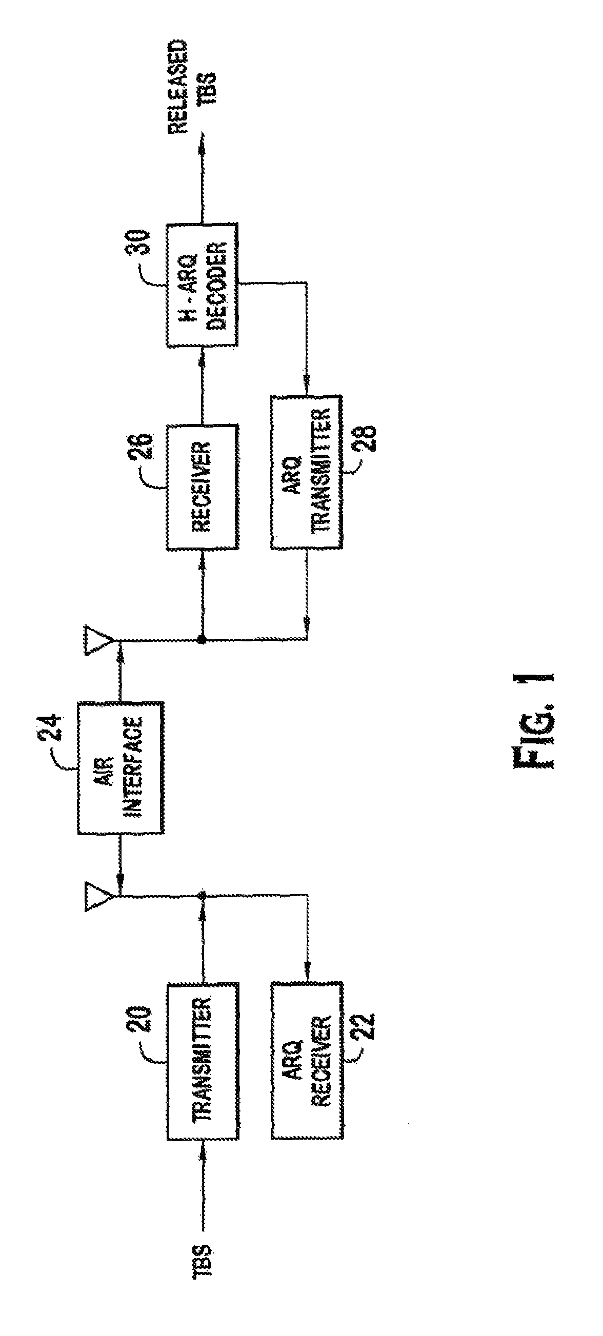
In such systems, a hybrid automatic repeat request (H-ARQ) mechanism may be used to maintain QOS and improve radio resource efficiency. A system using H-ARQ is shown in FIG. 1. A transmitter 20 transmits a TBS over the air interface 24 using a particular modulation and coding set. The TBS is received by a receiver 26. An H-ARQ decoder 30 decodes the received TBS. If the quality of the received data is unacceptable, an ARQ transmitter 28 requests a retransmission of the TBS. One approach to check the quality of the received TBS is a cyclic redundancy check (CRC). An ARQ receiver 22 receives the request and a retransmission of the TBS is made by the transmitter 20. Retransmissions may apply a more robust modulation and coding set to increase the possibility of successful delivery. The H-ARQ decoder 30 combines, the received TBS versions. A requirement for combining is that combined TBSs are identical. If the resulting quality is still insufficient, another retransmission is requested. If the resulting quality is sufficient, such as the combined TBS passes the CRC check, the received TBS is released for further processing. The H-ARQ mechanism allows for data received with unacceptable quality to be retransmitted to maintain the desired QOS.
In a system using both H-ARQ and AMC, a change in modulation and coding set may be determined necessary to achieve successful delivery of a requested TBS retransmission. In this situation, the maximum amount of physical data bits allowed within the TTI varies with the modulation and coding set.
Since only one TBS exists per TTI the effective user data rate corresponds to the TBS size applied to each TTI To achieve maximum data rates the largest TBS size is applied to the least robust modulation and coding set within the TTI When wireless channel conditions require a more robust modulation and coding set for successful transmission, such as when a TBS size cannot be supported within the TTI. Therefore, when operating at the maximum data rate, each time a more robust modulation and coding requirement is realized, all outstanding transmissions in H-ARQ processes that have not been successfully acknowledged must be discarded.
When Incremental Redundancy (IR) is applied, TBS data must remain constant in retransmissions for proper combining. Therefore, to guarantee that a TBS retransmission can be supported at a more robust modulation and coding set then the initial transmission, the TBS size used must correspond to the most robust MCS. However, when a TBS size allowed by the most robust modulation and coding set is applied the maximum data rate to the mobile is reduced, and when a less robust modulation and coding set is applied physical resources are not fully utilized.
When the TBS size is not supported by the more robust modulation and coding set, the TBS can be retransmitted using the old modulation and coding set. However, if the channel conditions dictate that a more robust modulation and coding set be used or the initial transmission was severally corrupted, the combining of the retransmitted TBSs may never pass, resulting in a transmission failure.
In current implementations, when a TBS cannot be successfully transmitted by AMC & H-ARQ mechanisms, recovery is handled by the radio link control (RLC) protocol (at layer two). Unlike a H-ARQ recovery of failed transmissions, the RLC error detection, data recovery and buffering of a TBS queued in the node-B, results in increased block error rates and data latency, potentially resulting in a failure to meet QOS requirements.
Accordingly, to provide maximum data rates with minimal H-ARQ transmission failures, it is desirable to support incremental redundancy and allow adaptation of modulation and coding sets in such systems.
SUMMARY
A user equipment comprises a transmitter and an adaptive modulation and coding controller. The transmitter is configured to transmit data over an air interface in a single transmission time interval with a first specified modulation and coding scheme, where the single transmission time interval has a plurality of transport block sets. In response to receiving a repeat request for retransmission of at least one particular transport block set, the transmitter retransmits the at least one of the particular transport block sets. The adaptive modulation and coding controller is configured to change the specified modulation and coding scheme to a second specified modulation and coding scheme, enabling a combining of a particular transport block set transmitted at the first specified modulation and coding scheme with a retransmitted version of the particular transport block set transmitted at the second specified modulation and coding scheme.
BRIEF DESCRIPTION OF THE DRAWINGS
FIG. 1 is an embodiment of a wireless H-ARQ communication system.
FIGS. 2A-2D are illustrations of a TTI having multiple TBSs.
FIGS. 3A-3C are embodiments of a wireless H-ARQ communication system using AMC with TTIs capable of having multiple TBSs.
FIG. 4 is a flow chart of changing the modulation and coding set prior to a H-ARQ retransmission.
FIG. 5 is an illustration of changing the modulation and coding set prior to a retransmission of a single TBS.
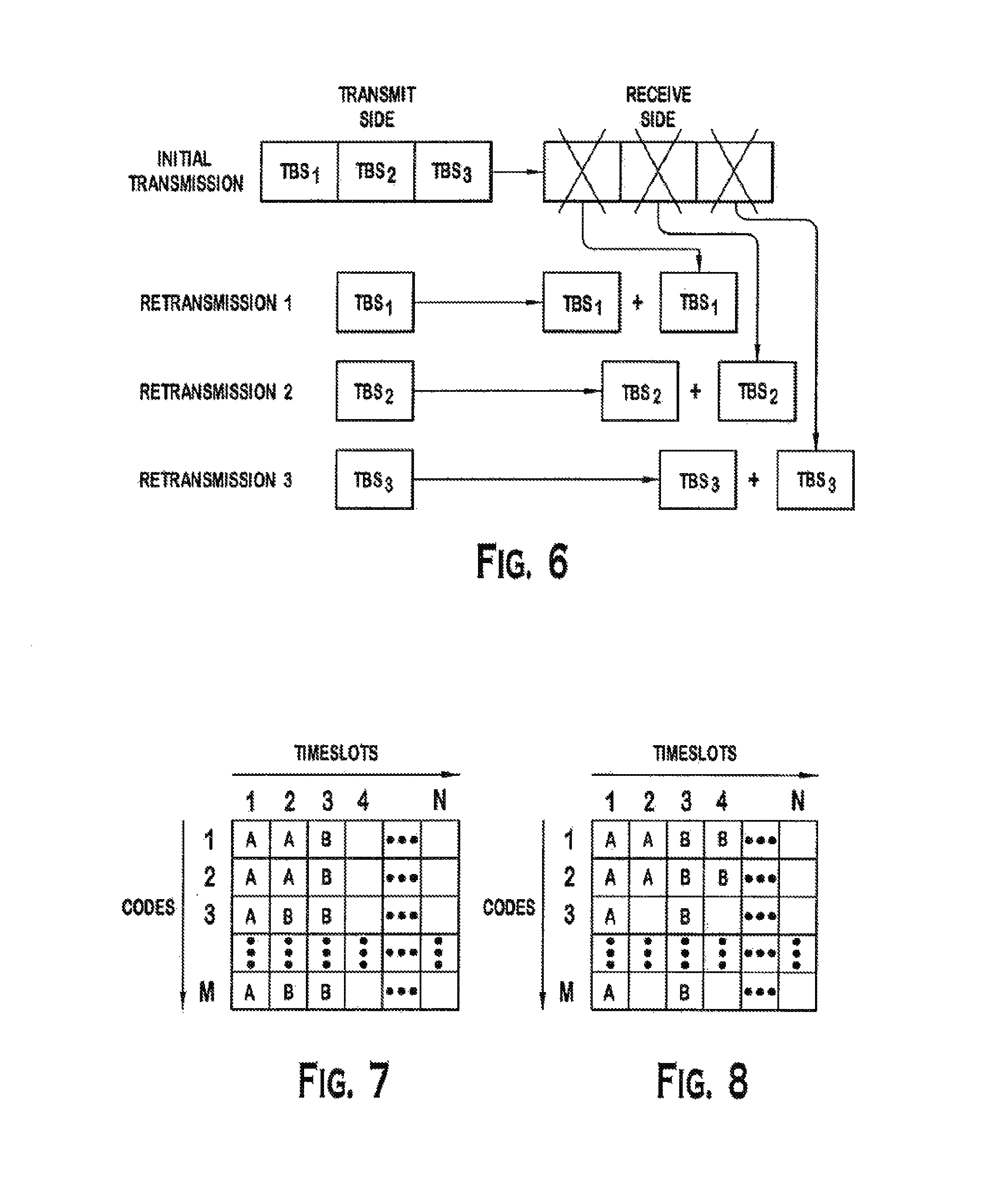
FIG. 6 is an illustration of changing the modulation and coding set prior to a retransmission of all three TBSs.
FIG. 7 is an illustration of overlapping TBSs in a TDD/CDMA communication system.
FIG. 8 is an illustration of non-overlapping TBSs in a TDD/CDMA communication system.
DETAILED DESCRIPTION OF THE PREFERRED EMBODIMENTS
FIGS. 2A, 2B, 2C and 2D illustrate a TTI having multiple TBSs, TBS.sub.1 to TBS.sub.N. FIG. 2A illustrates multiple TBSs dividing a TTI by time, such as for use in a TDD/CDMA system. FIG. 2B illustrates multiple TBSs divided by codes, such as for use in a FDD/CDMA or TDD/CDMA system. FIG. 2C illustrates dividing multiple TBSs by time and codes, such as for use in TDD/CDMA system. FIG. 2D illustrates dividing multiple TBSs by sub-carriers, such as for use in an OFDM system. Each TBS is sized to allow transmission with the most robust modulation coding set for the allocated resources. To illustrate, the most robust MCS may only have the capacity to support a maximum 2,000 bit TBS within the TTI. Although referred to as the most robust modulation coding set, in practice, the most robust set may actually be a more robust set, if the most robust modulation coding set is unlikely to be needed. The least robust modulation and coding set may have the capacity to support a maximum of 20,000 bit TBS within the TTI. Although referred to as the least robust modulation coding set, in practice, the least robust set may actually he a less robust set, if the least robust modulation coding set is unlikely to be needed.
The TBS is sized, preferably, to allow for transmission with the most robust modulation and coding set within a TTI. Then when the least robust modulation and coding set is applied, multiple TBSs of this size are applied within the TTI to achieve maximum data rates, and when greater transmission reliability is required for successful delivery the most robust modulation and coding set can be applied.
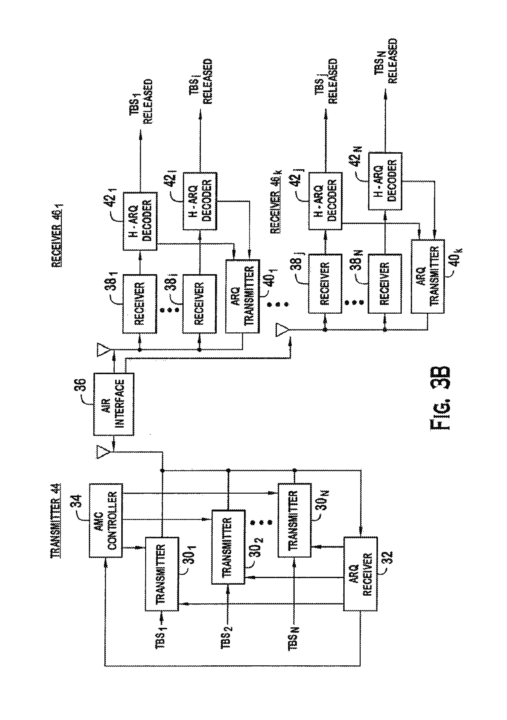
FIG. 3A is a simplified diagram of a transmitter 44 and receiver 46 for transmitting a TTI having one or multiple TBSs. The transmitter 44 may be located at either a user equipment or a base station/Node-B. The receiver 46 may be located at either a base station/Node-B or a user equipment. In current system implementations, AMC is typically only used in the downlink. Accordingly, the preferred implementation of transmission is for use in supporting AMC for the downlink. For other systems using AMC in the uplink, transport block set transmission can be applied to the uplink.
A transmitter 30.sub.1 to 30.sub.N (30) transmits each TBS, TBS.sub.1 to TBS.sub.N, over the air interface 36. The number of TBSs in the TTI depends on the TBS size and the modulation and coding set used for transmission. If the most robust modulation and coding set is used to ensure successful delivery, the TTI may only support one TBS. If a lesser robust modulation and coding set is used to achieve higher effective data rates, multiple TBSs are sent in the TTI. Alternately, some TBSs may be destined for a different receiver 46.sub.1 to 46.sub.K (46), as shown in FIG. 3B. Each TBS may also be sent to a different receiver 46.sub.1 to 46.sub.N (46), as shown in FIG. 3C. This flexibility allows for greater radio resource utilization and efficiency.
A receiver 38.sub.1 to 38.sub.N (38) receives each transmitted TBS. A H-ARQ decoder 42.sub.1 to 42.sub.N (42) decodes each received TBS. Although in FIG. 3 one transmitter 30, receiver 38 and H-ARQ decoder 42 is shown for each TBS, one transmitter 30, receiver 38 and H-ARQ decoder 42 may handle all the TBSs. For each TBS failing the quality test, a request for retransmission is made by the ARQ transmitter 40. An ARQ receiver 32 receives the request and directs the appropriate TBS(s) to be retransmitted. The retransmitted TBS(s) are combined by the H-ARQ decoder(s) 42 and another quality test is performed. Once the TBS(s) passes the quality test, it is released for further processing. Since a TTI can contain multiple TBSs, preferably, a failure in one TBS does not necessarily require retransmission of the entire TTI, which more efficiently utilizes the radio resources.
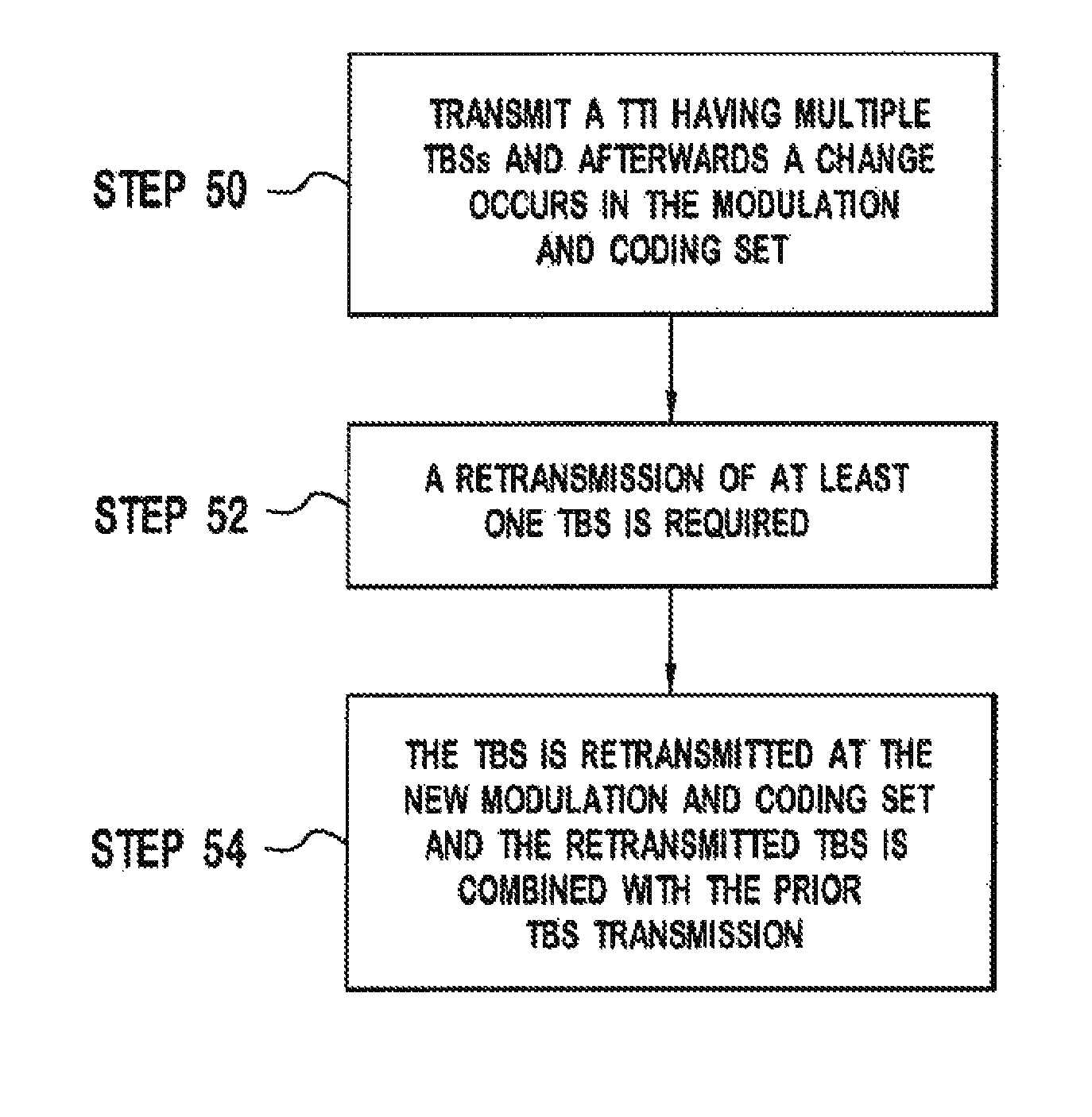
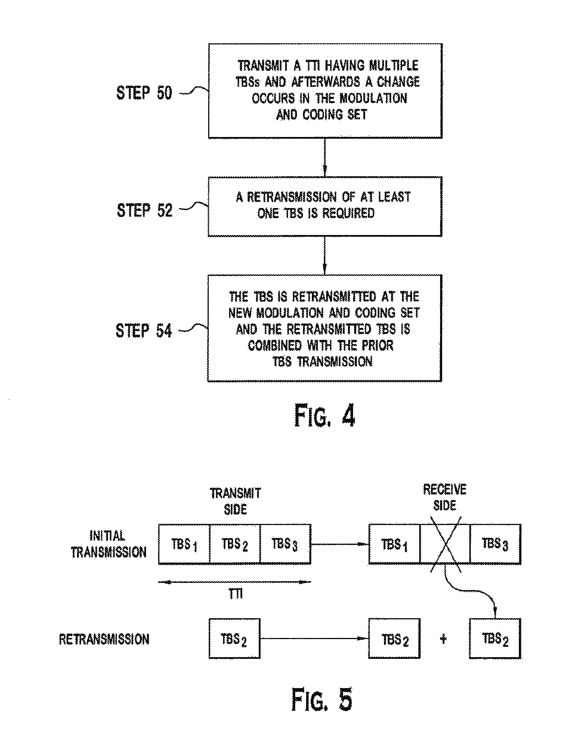
An AMC controller 34 is also shown in FIGS. 3A, 3B and 3C. If the channel conditions change, the AMC controller may initiate a change in the modulation and code set used to transfer data. FIG. 4 is a flow diagram illustrating such a change occurring in AMC between retransmissions. A TTI is transmitted having multiple TBSs and afterwards, a change in the modulation and coding set occurs, (step 50). To illustrate using FIG. 5, a TTI has three TBSs, TBS.sub.1, TBS.sub.2 and TBS.sub.3 applied at the least robust modulation and coding set to achieve the maximum data rate. The modulation and coding set in FIG. 5 changes so that only one TBS can be transmitted subsequently. Referring back to FIG. 4, at least one of the TBSs is received with an unacceptable quality and a retransmission is required, (step 52). In the illustration of FIG. 5, TBS.sub.2 requires retransmission, as shown by a large "X". The TBS requiring retransmission is sent at the new modulation and coding set and combined with the prior TBS transmission, (step 54). As shown in FIG. 5, only TBS.sub.2 is retransmitted and it is combined with the prior TBS.sub.2 transmission. Although this example illustrates sending only one TBS at the more robust modulation and coding set, it is also possible that two TBSs could be transmitted with the more robust modulation and coding set within the TTI.
FIG. 6 is an illustration of multiple TBSs requiring retransmission. Three TBSs, TBS.sub.1, TBS.sub.2 and TBS.sub.3, are transmitted in a TTI. A change in the modulation and coding set occurs such that only one TBS can be sent at a time. All three TBSs are received with an unacceptable quality. A request for retransmission is sent for all three TBSs. Sequentially, each TBS is retransmitted, as shown by retransmission 1, retransmission 2 and retransmission 3 in separate TTIs. The retransmitted TBSs are combined with the prior transmissions. A similar procedure is used, if two TBSs are transmitted with the more robust modulation and coding set within the TTI.
As illustrated, multiple TBSs allow for maximum data rates and incremental redundancy. A TTI can be transmitted at the least robust modulation and coding set achieving the maximum data rate and subsequent H-ARQ retransmission can be made at a more robust modulation and coding set ensuring greater probability for successful transmission. By allowing incremental redundancy, radio resources can be used more aggressively. A more aggressive (less robust) modulation and coding set can be used to achieve higher data rates and radio resource efficiency, since transmission can be made using a more conservative (more robust) set to maintain QOS, if channel conditions degrade.
In a TDD/CDMA communication system, such as in the 3GPP system, two preferred approaches for implementing multiple TBSs within a TTI use either overlapping or non-overlapping time slots. In overlapping time slots, the TBSs may overlap in time. As illustrated in FIG. 7, a first TBS in a TTI uses the resource units having an "A" in them. A resource unit is the use of one code in a time slot. A second TBS has the "B" resource units. As shown in FIG. 7, in the second time slot, both the first and second TBS are transmitted. Accordingly, the two TBSs' transmissions overlap in time.
In non-overlapping TB Ss, each time slot only contains one TBS of a TTI. As illustrated in FIG. 8, a first TBS ("A") is the only TBS in slots one and two. The second TBS ("B") is the only TBS in slots three and four.
In a FDD/CDMA communication system, such as in the third generation partnership project proposed system, transmissions occur simultaneously. In a FDD/CDMA system, preferably each TBS is assigned a different code/frequency pair for transmission. In an OFDM system, preferably each TBS is assigned a separate sub-carrier for transmission.
* * * * *
References
D00000
D00001
D00002
D00003
D00004
D00005
D00006
D00007
XML
uspto.report is an independent third-party trademark research tool that is not affiliated, endorsed, or sponsored by the United States Patent and Trademark Office (USPTO) or any other governmental organization. The information provided by uspto.report is based on publicly available data at the time of writing and is intended for informational purposes only.
While we strive to provide accurate and up-to-date information, we do not guarantee the accuracy, completeness, reliability, or suitability of the information displayed on this site. The use of this site is at your own risk. Any reliance you place on such information is therefore strictly at your own risk.
All official trademark data, including owner information, should be verified by visiting the official USPTO website at www.uspto.gov. This site is not intended to replace professional legal advice and should not be used as a substitute for consulting with a legal professional who is knowledgeable about trademark law.