Traceable cable with side-emitting optical fiber and method of forming the same
Bauco , et al.
U.S. patent number 10,228,526 [Application Number 15/054,380] was granted by the patent office on 2019-03-12 for traceable cable with side-emitting optical fiber and method of forming the same. This patent grant is currently assigned to Corning Optical Communications LLC. The grantee listed for this patent is Corning Optical Communications LLC. Invention is credited to Anthony Sebastian Bauco, Douglas Llewellyn Butler, Adam Kent Collier, Kevin Alton Lewis, Claudio Mazzali.


| United States Patent | 10,228,526 |
| Bauco , et al. | March 12, 2019 |
Traceable cable with side-emitting optical fiber and method of forming the same
Abstract
A traceable cable and method of forming the same. The cable includes at least one data transmission element, a jacket at least partially surrounding the at least one data transmission element, and a side-emitting optical fiber incorporated with and extending along at least a portion of the length of the cable. The side-emitting optical fiber has a core and a cladding substantially surrounding the core to define an exterior surface. The cladding has spaced apart scattering sites penetrating the exterior surface along the length of the optical fiber. The scattering sites scattering light so that the scattered light is emitted from the side-emitting optical fiber at discrete locations. When light is transmitted through the core, light scattered from the side-emitting optical fiber allows the cable to be traced along at least a portion of the length thereof.
| Inventors: | Bauco; Anthony Sebastian (Horseheads, NY), Butler; Douglas Llewellyn (Painted Post, NY), Collier; Adam Kent (Montour Falls, NY), Lewis; Kevin Alton (Montour Falls, NY), Mazzali; Claudio (Painted Post, NY) | ||||||||||
|---|---|---|---|---|---|---|---|---|---|---|---|
| Applicant: |
|
||||||||||
| Assignee: | Corning Optical Communications
LLC (Hickory, NC) |
||||||||||
| Family ID: | 57005087 | ||||||||||
| Appl. No.: | 15/054,380 | ||||||||||
| Filed: | February 26, 2016 |
Prior Publication Data
| Document Identifier | Publication Date | |
|---|---|---|
| US 20160291277 A1 | Oct 6, 2016 | |
Related U.S. Patent Documents
| Application Number | Filing Date | Patent Number | Issue Date | ||
|---|---|---|---|---|---|
| 14690752 | Apr 20, 2015 | ||||
| 62140620 | Mar 31, 2015 | ||||
| Current U.S. Class: | 1/1 |
| Current CPC Class: | G02B 6/443 (20130101); G02B 6/001 (20130101); G02B 6/0006 (20130101); G02B 6/447 (20130101) |
| Current International Class: | G02B 6/44 (20060101); F21V 8/00 (20060101) |
References Cited [Referenced By]
U.S. Patent Documents
| 3942859 | March 1976 | Korodi |
| 4412936 | November 1983 | Khmelkov et al. |
| 4466697 | August 1984 | Daniel |
| 4557552 | December 1985 | Newton et al. |
| 4637686 | January 1987 | Iwamoto et al. |
| 4712858 | December 1987 | Presby |
| 4755018 | July 1988 | Heng et al. |
| 4763984 | August 1988 | Awai et al. |
| 4923274 | May 1990 | Dean |
| 4995691 | February 1991 | Purcell, Jr. |
| 5006806 | April 1991 | Rippingdale et al. |
| 5017873 | May 1991 | Rippingdale et al. |
| 5040867 | August 1991 | de Jong et al. |
| 5122750 | June 1992 | Rippingdale et al. |
| 5179611 | January 1993 | Umeda et al. |
| 5206065 | April 1993 | Rippingale et al. |
| 5305405 | April 1994 | Emmons et al. |
| 5329348 | July 1994 | Nimura et al. |
| 5333228 | July 1994 | Kingstone |
| 5377292 | December 1994 | Bartling et al. |
| 5394496 | February 1995 | Caldwell et al. |
| 5395362 | March 1995 | Sacharoff et al. |
| 5432876 | July 1995 | Appeldorn |
| 5463706 | October 1995 | Dumont et al. |
| 5500913 | March 1996 | Allen |
| 5591160 | January 1997 | Reynard |
| 5666453 | September 1997 | Dannenmann |
| 5741152 | April 1998 | Boutros |
| 5764043 | June 1998 | Czosnowski et al. |
| 5835654 | November 1998 | Bergmann |
| 5979188 | November 1999 | Ojha |
| 5982967 | November 1999 | Mathis et al. |
| 6126325 | October 2000 | Yamane et al. |
| 6137928 | October 2000 | Albrecht |
| 6137935 | October 2000 | Bohme et al. |
| 6173097 | January 2001 | Throckmorton et al. |
| 6257750 | July 2001 | Strasser et al. |
| 6293081 | September 2001 | Grulick et al. |
| 6301418 | October 2001 | Freier |
| 6311000 | October 2001 | Schneider |
| 6314713 | November 2001 | Fitz et al. |
| 6317553 | November 2001 | Harper, Jr. et al. |
| 6347172 | February 2002 | Keller et al. |
| 6356690 | March 2002 | McAlpine et al. |
| 6379054 | April 2002 | Throckmorton et al. |
| 6388194 | May 2002 | Ryeczek |
| 6403947 | June 2002 | Hoyt et al. |
| 6425694 | July 2002 | Szilagyi et al. |
| 6439780 | August 2002 | Mudd et al. |
| 6456768 | September 2002 | Boncek et al. |
| 6456785 | September 2002 | Evans |
| 6471412 | October 2002 | Belenkiy et al. |
| 6519396 | February 2003 | Schneider et al. |
| 6526200 | February 2003 | Davie |
| 6532328 | March 2003 | Kline |
| 6554485 | April 2003 | Beatty et al. |
| 6560390 | May 2003 | Grulick et al. |
| 6577243 | June 2003 | Dannenmann et al. |
| 6596943 | July 2003 | Ward |
| 6606431 | August 2003 | Unsworth |
| 6678449 | January 2004 | Thompson et al. |
| 6695491 | February 2004 | Leeman et al. |
| 6704479 | March 2004 | Koplow |
| 6710254 | March 2004 | Yueh |
| 6712524 | March 2004 | Beatty et al. |
| 6728453 | April 2004 | Petryszak |
| 6798956 | September 2004 | Morrision |
| 6816661 | November 2004 | Barnes et al. |
| 6823120 | November 2004 | Hurley et al. |
| 6906505 | June 2005 | Brunet et al. |
| 6933438 | August 2005 | Watts et al. |
| 6969273 | November 2005 | Chen |
| 6979223 | December 2005 | Chen |
| 7020369 | March 2006 | Lodge, Jr. et al. |
| 7029137 | April 2006 | Lionetti et al. |
| 7038135 | May 2006 | Chan et al. |
| 7049937 | May 2006 | Zweig et al. |
| 7090411 | August 2006 | Brown |
| 7121707 | October 2006 | Currie et al. |
| 7164819 | January 2007 | Jenson et al. |
| 7217152 | May 2007 | Xin et al. |
| 7221284 | May 2007 | Scherer et al. |
| 7242831 | July 2007 | Fee |
| 7313304 | December 2007 | Andrews et al. |
| 7401961 | July 2008 | Longatti et al. |
| 7406231 | July 2008 | Beck et al. |
| 7433565 | October 2008 | Joseph et al. |
| 7524082 | April 2009 | North |
| 7544909 | June 2009 | Dhir |
| 7572066 | August 2009 | De Jong et al. |
| 7596293 | September 2009 | Isenhour et al. |
| 7603020 | October 2009 | Wakileh et al. |
| 7618175 | November 2009 | Hulse |
| 7620279 | November 2009 | Joseph |
| 7653277 | January 2010 | Andrews et al. |
| 7671279 | March 2010 | Yin |
| 7748860 | July 2010 | Brunet |
| 7817884 | October 2010 | Demeritt et al. |
| 7920764 | April 2011 | Kewitsch |
| 7932805 | April 2011 | Darr et al. |
| 7948226 | May 2011 | Rathbun, II et al. |
| 8000576 | August 2011 | Chen et al. |
| 8102169 | January 2012 | Law et al. |
| 8150227 | April 2012 | Kewitsch |
| 8152385 | April 2012 | De Jong et al. |
| 8167471 | May 2012 | Moritz |
| 8314603 | November 2012 | Russell |
| 8322871 | December 2012 | Knaggs et al. |
| 8331752 | December 2012 | Biribuze et al. |
| 8408029 | April 2013 | De Angelis et al. |
| 8414319 | April 2013 | Patel et al. |
| 8428405 | April 2013 | Kewitsch |
| 8492448 | July 2013 | Dewa et al. |
| 8509579 | August 2013 | Martin-Lopez |
| 8545076 | October 2013 | Bickham et al. |
| 8548293 | October 2013 | Kachmar |
| 8582939 | November 2013 | Gimblet et al. |
| 8582940 | November 2013 | Abernathy et al. |
| 8591087 | November 2013 | Bickham et al. |
| 8620123 | December 2013 | Dean, Jr. et al. |
| 8620125 | December 2013 | Button et al. |
| 8683827 | April 2014 | De Angelis et al. |
| 8708724 | April 2014 | Patel et al. |
| 8724842 | May 2014 | Sumitani et al. |
| 8724942 | May 2014 | Logunov et al. |
| 8770525 | July 2014 | Donaldson et al. |
| 8787717 | July 2014 | Logunov |
| 8791829 | July 2014 | Gustafsson et al. |
| 8798419 | August 2014 | Wessels, Jr. et al. |
| 8805141 | August 2014 | Fewkes et al. |
| 8896286 | November 2014 | Abuelsaad et al. |
| 8896287 | November 2014 | Abuelsaad et al. |
| 8897612 | November 2014 | Logunov |
| 8903212 | December 2014 | Kachmar |
| 8909013 | December 2014 | Jiang et al. |
| 8929703 | January 2015 | Logunov et al. |
| 9025923 | May 2015 | Logunov et al. |
| 9073243 | July 2015 | Gimblet et al. |
| 9146347 | September 2015 | Logunov et al. |
| 9182561 | November 2015 | Bauco et al. |
| 9196975 | November 2015 | Scherer et al. |
| 9271709 | March 2016 | Grey et al. |
| 9304278 | April 2016 | Bauco et al. |
| 9388975 | July 2016 | Wenger |
| 9429731 | August 2016 | Bookbinder et al. |
| 9435713 | September 2016 | Collier et al. |
| 9448380 | September 2016 | Mogensen |
| 9507096 | November 2016 | Isenhour et al. |
| 9529167 | December 2016 | Wu |
| 9541694 | January 2017 | Tissot |
| 9709750 | July 2017 | Kuang et al. |
| 2001/0002220 | May 2001 | Trockmorton et al. |
| 2001/0048797 | December 2001 | Van Dijk et al. |
| 2002/0009282 | January 2002 | Grulick et al. |
| 2002/0036775 | March 2002 | Wolleschensky et al. |
| 2002/0037133 | March 2002 | Unsworth |
| 2002/0136497 | September 2002 | McGarry et al. |
| 2002/0159735 | October 2002 | Edvold et al. |
| 2002/0185299 | December 2002 | Giebel |
| 2003/0002830 | January 2003 | Petryszak |
| 2003/0016924 | January 2003 | Thompson et al. |
| 2003/0108270 | June 2003 | Brimacombe et al. |
| 2003/0206519 | November 2003 | Sanders et al. |
| 2003/0222786 | December 2003 | Dannenmann et al. |
| 2004/0022504 | February 2004 | Hurley et al. |
| 2004/0052473 | March 2004 | Seo et al. |
| 2004/0146254 | July 2004 | Morrison |
| 2004/0160774 | August 2004 | Lionetti et al. |
| 2004/0179777 | September 2004 | Buelow, II et al. |
| 2004/0196648 | October 2004 | Franklin et al. |
| 2005/0052174 | March 2005 | Angelo et al. |
| 2005/0089284 | April 2005 | Ma |
| 2005/0212503 | September 2005 | Deibele |
| 2006/0104578 | May 2006 | Herbst |
| 2006/0133750 | June 2006 | Lee |
| 2006/0140562 | June 2006 | Joseph et al. |
| 2006/0193575 | August 2006 | Greenwood et al. |
| 2006/0232385 | October 2006 | Scherer et al. |
| 2006/0285350 | December 2006 | Wang |
| 2007/0116402 | May 2007 | Slade et al. |
| 2007/0153508 | July 2007 | Nall et al. |
| 2007/0217749 | September 2007 | Jong et al. |
| 2008/0080820 | April 2008 | Andrews et al. |
| 2008/0087082 | April 2008 | Andrews et al. |
| 2008/0121171 | May 2008 | Hulsey |
| 2008/0198618 | August 2008 | North |
| 2008/0204235 | August 2008 | Cook |
| 2008/0273844 | November 2008 | Kewitsch |
| 2009/0027873 | January 2009 | Tarlton |
| 2009/0297104 | December 2009 | Kachmar |
| 2009/0299440 | December 2009 | Slatkine |
| 2010/0021114 | January 2010 | Chen et al. |
| 2010/0066254 | March 2010 | Ott et al. |
| 2010/0148747 | June 2010 | Rathbun, II et al. |
| 2010/0166374 | July 2010 | Lapp |
| 2010/0274235 | October 2010 | Mihajlovic et al. |
| 2011/0034068 | February 2011 | Russell |
| 2011/0085776 | April 2011 | Biribuze et al. |
| 2011/0103747 | May 2011 | Chang et al. |
| 2011/0103757 | May 2011 | Alkemper et al. |
| 2011/0122646 | May 2011 | Bickham et al. |
| 2011/0150488 | June 2011 | Kewitsch |
| 2011/0305035 | December 2011 | Bickham et al. |
| 2012/0019900 | January 2012 | Kitson et al. |
| 2012/0219259 | August 2012 | Kewitsch |
| 2012/0275178 | November 2012 | Logunov |
| 2012/0275180 | November 2012 | Button et al. |
| 2012/0275745 | November 2012 | Logunov |
| 2013/0021597 | January 2013 | Carlson, Jr. et al. |
| 2013/0088888 | April 2013 | Fewkes et al. |
| 2013/0107565 | May 2013 | Genier |
| 2013/0156392 | June 2013 | Logunov |
| 2013/0201001 | August 2013 | Ratnakar |
| 2013/0209045 | August 2013 | Dean, Jr. |
| 2013/0272014 | October 2013 | Logunov et al. |
| 2013/0341922 | December 2013 | Jimenez Buendia |
| 2014/0016904 | January 2014 | Kachmar |
| 2014/0070639 | March 2014 | Tamura |
| 2014/0221763 | August 2014 | Vayser et al. |
| 2014/0227438 | August 2014 | Dean, Jr. et al. |
| 2014/0270639 | September 2014 | James, III et al. |
| 2014/0355295 | December 2014 | Kuchinisky et al. |
| 2014/0363134 | December 2014 | Bookbinder |
| 2015/0043875 | February 2015 | Bookbinder et al. |
| 2015/0049992 | February 2015 | Bauco |
| 2015/0369986 | December 2015 | Logunov et al. |
| 2016/0139353 | May 2016 | Bauco et al. |
| 2016/0202418 | July 2016 | Fortin et al. |
| 2016/0231521 | August 2016 | Smith et al. |
| 2016/0313483 | October 2016 | Chomycz |
| 2016/0313513 | October 2016 | Wijbrans et al. |
| 2016/0377818 | December 2016 | Tong et al. |
| 2017/0207585 | July 2017 | Butler et al. |
| 2017/0293102 | October 2017 | Bauco et al. |
| 2018/0128996 | May 2018 | Sawicki et al. |
| 200941319 | Aug 2007 | CN | |||
| 201419706 | Mar 2010 | CN | |||
| 201429706 | Mar 2010 | CN | |||
| 102589728 | Jul 2012 | CN | |||
| 201305952 | Jul 2012 | CN | |||
| 202305952 | Jul 2012 | CN | |||
| 203241575 | Oct 2013 | CN | |||
| 4413597 | Oct 1995 | DE | |||
| 10239602 | Feb 2004 | DE | |||
| 102007025494 | Dec 2008 | DE | |||
| 102009015263 | Oct 2010 | DE | |||
| 202015007044 | Dec 2015 | DE | |||
| 0874191 | Oct 1998 | EP | |||
| 0952589 | Oct 1999 | EP | |||
| 1168025 | Jan 2002 | EP | |||
| 2113969 | Nov 2009 | EP | |||
| 2260198 | Apr 1993 | GB | |||
| 2375898 | Nov 2002 | GB | |||
| 57011305 | Jun 1980 | JP | |||
| 57-11305 | Jan 1982 | JP | |||
| 59182404 | Apr 1983 | JP | |||
| 59-182404 | Oct 1984 | JP | |||
| 61-139221 | Jun 1986 | JP | |||
| 61139221 | Jun 1986 | JP | |||
| 61-161827 | Oct 1986 | JP | |||
| 61161827 | Oct 1986 | JP | |||
| 2-55506 | Feb 1990 | JP | |||
| 1990055506 | Feb 1990 | JP | |||
| 2-108007 | Apr 1990 | JP | |||
| 2108007 | Apr 1990 | JP | |||
| 2108008 | Apr 1990 | JP | |||
| 02108808 | Apr 1990 | JP | |||
| 6-017157 | Mar 1994 | JP | |||
| 6017157 | Mar 1994 | JP | |||
| 06130253 | May 1994 | JP | |||
| 9-178956 | Jul 1997 | JP | |||
| 9178956 | Jul 1997 | JP | |||
| 9-237524 | Sep 1997 | JP | |||
| 9237524 | Sep 1997 | JP | |||
| 2008153030 | Jul 2008 | JP | |||
| 2009244288 | Oct 2009 | JP | |||
| 2010237233 | Oct 2010 | JP | |||
| 2013196960 | Sep 2013 | JP | |||
| 10-0875507 | Dec 2008 | KR | |||
| 875507 | Dec 2008 | KR | |||
| 1998034144 | Aug 1998 | WO | |||
| 1999024856 | May 1999 | WO | |||
| 0011484 | Mar 2000 | WO | |||
| 2000011484 | Mar 2000 | WO | |||
| 2005106899 | Nov 2005 | WO | |||
| 2006044177 | Apr 2006 | WO | |||
| 2006113114 | Oct 2006 | WO | |||
| 2007053371 | May 2007 | WO | |||
| 2008048955 | Apr 2008 | WO | |||
| 2010011299 | Jan 2010 | WO | |||
| 2010021896 | Feb 2010 | WO | |||
| 2011063214 | May 2011 | WO | |||
| 2013055842 | Apr 2013 | WO | |||
| 2013059811 | Apr 2013 | WO | |||
| 2013122825 | Aug 2013 | WO | |||
| 2014026300 | Feb 2014 | WO | |||
| 2015000194 | Jan 2015 | WO | |||
Other References
|
US. Appl. No. 14/295,844, Bookbinder et al., filed Jun. 4, 2014, 25 pages. cited by applicant . Side Emitting Super Glowing Fiber, Diode Lasers, Meshtel Lasers Fiber Optics Communications, Jan. 1, 2013, 1 page. cited by applicant . Specifications of our Fiber and Cable, N.p., n.d. Web, Aug. 9, 2013, 2 pages. cited by applicant . Polymer Photonics: An Overview, M. Rajesh, 2011, 38 pages. cited by applicant . Optical fiber with nanostructured cladding of TiO2 nanoparticles self-assembled onto a side polished fiber and its temperature sensing, Lu et al., Optics Express, vol. 22, No. 26, Dec. 29, 2014, 7 pages, downloaded from internet on Jan. 5, 2015. cited by applicant . Schott SpectraStream Glass Harnesses, Rev. 11/06, 2 pages. cited by applicant . Side-Emitting Fibers Brighten Our World in New Ways, Janis Spigulis, Oct. 2005, 6 pages. cited by applicant . Patent Cooperation Treaty International Search Report, Application No. PCT/US2013/025262, Jul. 16, 2013, 7 pages. cited by applicant . Patent Cooperation Treaty International Search Report, Application No. PCT/US2014/049524, Jan. 20, 2015, 5 pages. cited by applicant . Patent Cooperation Treaty International Search Report, Application No. PCT/US2014/049525, Jan. 23, 2015, 18 pages. cited by applicant . Side Emitting Super Glowing Fiber, MeshTel--INTELITE, Inc., 1996-2015, downloaded from Web Jan. 5, 2016, 2 pages. cited by applicant . Super Vision Side Glow Cable, TriNorth Lighting, Inc., 2016, downloaded from Web Jan. 5, 2016, 2 pages. cited by applicant . U.S. Appl. No. 62/193,638, U.S. Appl. No. 62/221,769--Listed in ID as 26113. cited by applicant . U.S. Appl. No. 14/791,924, filed May 20, 2015. cited by applicant . U.S. Appl. No. 15/000,128, filed Jan. 19, 2016. cited by applicant . U.S. Appl. No. 15/054,380, filed Mar. 31, 2015. cited by applicant . U.S. Appl. No. 15/142,853, filed Apr. 29, 2016. cited by applicant . U.S. Appl. No. 62/193,638, filed Jul. 17, 2015. cited by applicant . U.S. Appl. No. 62/193,643, filed Jul. 17, 2015. cited by applicant . U.S. Appl. No. 62/221,769, filed Sep. 22, 2015. cited by applicant . U.S. Appl. No. 62/221,774, filed Sep. 22, 2015. cited by applicant . U.S. Appl. No. 62/248,490, filed Oct. 30, 2015. cited by applicant . International Search Report and Written Opinion PCT/US2016/020542 dated Jun. 7, 2016. cited by applicant . International Search Report and Written Opinion PCT/US2016/031624 dated Aug. 31, 2016. cited by applicant . http://www.dexim.net/list.php?id=7, Dexim product reference, downloaded from the web Feb. 24, 2016. 2 pages. cited by applicant . Kremenakova, et al., "Characterizaion of Side EmmittingPolymeric Optical Fibres," Jounal of Fiber Bioengineering & Informatics 5:4 (2012) pp. 423-431, http://www.jfbi.org, Dec. 2012. cited by applicant . Fiber Optic Products, Inc., "Specifications of our Fiber and Cable," n.d. Retrieved on Aug. 9, 2013, 2 pages. cited by applicant . M. Rajesh, "Polymer Photonics: An Overview," Fabrication and Characterisation, 2011, 38 pages. cited by applicant . Schott, "SpectraStream Glass Harnesses," Rev. Nov. 2006, 2 pages. cited by applicant . Spigulis, J., "Side-Emitting Fibers Brighten Our World in New Ways," Oct. 2005, Retrieved from www.osa-opn.org, 6 pages. cited by applicant . Patent Cooperation Treaty, International Search Report, Application No. PCT/US2013/025262, dated Jul. 16, 2013, 7 pages. cited by applicant . "Super Vision Fiber Optics Side Glow Cables," TriN01ihLighting.com, Tri North Lighting, Inc., n.d., Web. Aug. 1, 2013. cited by applicant . U.S. Appl. No. 13/431,565, filed Mar. 27, 2012, David L. Dean, Jr., 32 pages. cited by applicant . European Search Report, Application No. 15168466.9-1553, dated Dec. 17, 2015, 9 pages. cited by applicant . Patent Cooperation Treaty, International Search Report for PCT/US2015/060558, dated Feb. 9, 2016, 5 pages. cited by applicant . Patent Cooperation Treaty International Search Report, Application No. PCT/US2014/049524, dated Jan. 20, 2015, 5 pages. cited by applicant . "Diode Lasers, Fiber Optics, IR, Red, Green, Blue Diode Lasers, Laser Diode, Fiber Illuminators, Fiber Optics, Coupler, Galvonarneters, Laser Show Acessories," Jan 1, 2013, httn://www.meshtel.com/, 1 oage. cited by applicant . Patent Cooperation Treaty, International Search Report, PCT/US2014/049525, dated Jan. 23, 2015, 18 pages. cited by applicant . U.S. Appl. No. 14/295,844, Bookbinder filed Jun. 4, 2014, 25 pages. cited by applicant . Patent Cooperation Treaty, International Search Report and Written Opinion for International Application No. PCT/US2014/041510, dated Sep. 18, 2014, 10 pages. cited by applicant . International Searching Authority Invitation to Pay Additional Fees PCT/US2016/055497 dated Dec. 19, 2016. cited by applicant . Non-Final Office Action for U.S. Appl. No. 14/690,752, dated Oct. 2, 2015, 12 pages. cited by applicant . International Preliminary Report on Patentability for PCT/US2016/020542, dated Oct. 12, 2017, 8 pages. cited by applicant . International Search Report and Written Opinion PCT/US2016/042414 dated Oct. 5, 2016. cited by applicant . International Searching Authority Invitation to Pay Additional Search Fees PCT/US2016/042416 dated Oct. 7, 2016. cited by applicant . Endruweit et al. "Spectroscopic experiments regarding the efficiency of side emission optical fibres in the UV-A and visible blue spectrum", Optics and Lasers in Engineering 46 (2008) pp. 97-105. cited by applicant. |
Primary Examiner: Pak; Sung H
Attorney, Agent or Firm: Branham; Robert L.
Parent Case Text
PRIORITY APPLICATION
This application is a continuation of U.S. application Ser. No. 14/690,752 filed on Apr. 20, 2015, which claims the benefit of priority to Provisional Application Ser. No. 62/140,620, filed on Mar. 31, 2015, both applications being relied upon and incorporated herein by reference their entireties.
Claims
What is claimed is:
1. A traceable cable having a length, comprising: at least one data transmission element; a jacket at least partially surrounding the at least one data transmission element; and a side-emitting optical fiber incorporated with and extending along at least a portion of the length of the traceable cable, wherein the side-emitting optical fiber is at least partially embedded in the jacket, the side-emitting optical fiber comprising: a core having a first index of refraction; a cladding having a second index of refraction less than the first index of refraction, the cladding substantially surrounding the core, the cladding having an exterior surface and spaced apart laser-ablated scattering sites penetrating the exterior surface along a length of the side-emitting optical fiber, wherein the laser-ablated scattering sites each comprise an optically rough surface portion of the cladding; and an acrylic coating on the exterior surface of the cladding and on the optically rough surface portion of the cladding.
2. The traceable cable of claim 1, wherein the core comprises glass or polymer having diameter between about 100 and about 250 microns, and further wherein the cladding comprises fluoro-acrylate.
3. The traceable cable of claim 1, wherein the laser-ablated scattering sites extend completely through the cladding.
4. The traceable cable of claim 1, wherein the laser-ablated scattering sites do not extend to the core.
5. The traceable cable of claim 1, wherein the laser-ablated scattering sites are configured to scatter light in all directions around a lengthwise axis of the side-emitting optical fiber.
6. The traceable cable of claim 1, wherein at least some of the laser-ablated scattering sites extend fully around a circumference of the cladding.
7. The traceable cable of claim 1, wherein at least some of the laser-ablated scattering sites extend only partially around a circumference of the cladding.
8. The traceable cable of claim 1, wherein the laser-ablated scattering sites are periodically spaced along the length of the side-emitting optical fiber between about 4 cm and about 1 m apart.
9. The traceable cable of claim 1, wherein the side-emitting optical fiber is a step-index optical fiber.
10. The traceable cable of claim 1, wherein a depth of the laser-ablated scattering sites varies as a function of the distance from an end of the side-emitting optical fiber.
11. The traceable cable of claim 1, wherein each laser-ablated scattering site has a magnitude between about 0.1 mm and about 50 mm along the length of the side-emitting optical fiber.
12. The traceable cable of claim 11, wherein the magnitude varies as a function of the distance from an end of the side-emitting optical fiber.
13. The traceable cable of claim 12, further comprising an ink layer applied to the acrylic coating for further diffusion of scattered light.
14. The traceable cable of claim 1, wherein the at least one data transmission element is an optical fiber.
15. The traceable cable of claim 1, wherein the jacket comprises a pigmented portion and an un-pigmented portion, the side-emitting optical fiber being at least partially embedded in the un-pigmented portion.
16. A traceable cable having a length, comprising: a first connector; a second connector; at least one data transmission element extending between the first connector and the second connector; a jacket at least partially surrounding the at least one data transmission element; and a side-emitting optical fiber extending along at least a portion of the length of the traceable cable, wherein the side-emitting optical fiber is at least partially embedded in the jacket, the side-emitting optical fiber comprising: a core having a first index of refraction; a cladding having a second index of refraction less than the first index of refraction, the cladding substantially surrounding the core, the cladding having an exterior surface and spaced apart laser-ablated scattering sites penetrating the exterior surface along a length of the side-emitting optical fiber, wherein the laser-ablated scattering sites each comprise an optically rough surface portion of the cladding; and an acrylic coating over the exterior surface of the cladding and on the optically rough surface portion of the cladding.
17. A traceable cable having a length, comprising: at least one data transmission element extending between a first connector and a second connector; a jacket at least partially surrounding the at least one data transmission element, wherein the jacket comprises a first pigmented portion and a second pigmented portion, wherein the first pigmented portion comprises more pigment than the second pigmented portion; and a side-emitting optical fiber extending along at least a portion of the length of the traceable cable, wherein the side-emitting optical fiber is at least partially embedded in the second pigmented portion of the jacket, the side-emitting optical fiber comprising: a core having a first index of refraction; a cladding having a second index of refraction less than the first index of refraction, the cladding substantially surrounding the core, the cladding having an exterior surface and spaced apart laser-ablated scattering sites penetrating the exterior surface along a length of the side-emitting optical fiber, wherein the laser-ablated scattering sites each comprise an optically rough surface portion of the cladding; and an acrylic coating over the exterior surface of the cladding and on the optically rough surface portion of the cladding.
18. The traceable cable of claim 17, wherein the second pigmented portion is at least partially transparent.
19. The traceable cable of claim 17, wherein the first pigmented portion comprises a pigment selected to identify the traceable cable.
20. The traceable cable of claim 17, wherein a depth of the laser-ablated scattering sites varies as a function of the distance from an end of the side-emitting optical fiber.
21. A traceable cable having a length, comprising: at least one data transmission element; a jacket at least partially surrounding the at least one data transmission element; and a side-emitting optical fiber incorporated with and extending along at least a portion of the length of the traceable cable, wherein the side-emitting optical fiber is at least partially embedded in the jacket, the side-emitting optical fiber comprising: a core having a first index of refraction; a cladding having a second index of refraction less than the first index of refraction, the cladding substantially surrounding the core, the cladding having an exterior surface and spaced apart laser-ablated scattering sites penetrating the exterior surface along a length of the side-emitting optical fiber, wherein the laser-ablated scattering sites each comprise an optically rough surface portion of the cladding, wherein at least some of the laser-ablated scattering sites extend at least partially around a circumference of the side-emitting optical fiber; and an acrylic coating on the exterior surface of the cladding and on the optically rough surface portion of the cladding.
22. The traceable cable of claim 21, wherein at least some of the laser-ablated scattering sites extend fully around a circumference of the cladding.
23. The traceable cable of claim 21, wherein at least some of the laser-ablated scattering sites extend only partially around a circumference of the cladding.
24. A traceable cable having a length, comprising: at least one data transmission element; a jacket at least partially surrounding the at least one data transmission element; and a side-emitting optical fiber incorporated with and extending along at least a portion of the length of the traceable cable, wherein the side-emitting optical fiber is at least partially embedded in the jacket, the side-emitting optical fiber comprising: a core having a first index of refraction; a cladding having a second index of refraction less than the first index of refraction, the cladding substantially surrounding the core, the cladding having an exterior surface and spaced apart laser-ablated scattering sites penetrating the exterior surface along a length of the side-emitting optical fiber, wherein the laser-ablated scattering sites each comprise an optically rough surface portion of the cladding, wherein the laser-ablated scattering sites are periodically spaced along the length at least 1 cm apart; and an acrylic coating on the exterior surface of the cladding and on the optically rough surface portion of the cladding.
25. A traceable cable having a length, comprising: at least one data transmission element; a jacket at least partially surrounding the at least one data transmission element; and a side-emitting optical fiber incorporated with and extending along at least a portion of the length of the traceable cable, wherein the side-emitting optical fiber is at least partially embedded in the jacket, the side-emitting optical fiber comprising: a core having a first index of refraction; a cladding having a second index of refraction less than the first index of refraction, the cladding substantially surrounding the core and having a thickness between about 4% and about 40% of a diameter of the core, the cladding having an exterior surface and spaced apart laser-ablated scattering sites penetrating the exterior surface along a length of the side-emitting optical fiber, wherein the laser-ablated scattering sites each comprise an optically rough surface portion of the cladding; and an acrylic coating on the exterior surface of the cladding and on the optically rough surface portion of the cladding.
26. A traceable cable having a length, comprising: at least one data transmission element; a jacket at least partially surrounding the at least one data transmission element; and a side-emitting optical fiber incorporated with and extending along at least a portion of the length of the traceable cable, wherein the side-emitting optical fiber is at least partially embedded in the jacket, the side-emitting optical fiber comprising: a core having a first index of refraction; a cladding having a second index of refraction less than the first index of refraction, the cladding substantially surrounding the core, the cladding having an exterior surface and spaced apart laser-ablated scattering sites penetrating the exterior surface along a length of the side emitting optical fiber, wherein the laser-ablated scattering sites each comprise an optically rough surface portion of the cladding; and an acrylic coating on the exterior surface of the cladding and on the optically rough surface portion of the cladding, the acrylic coating having a thickness between about 10 microns and about 70 microns.
Description
BACKGROUND
This disclosure generally relates to waveguides that scatter light from the side thereof. More particularly, this disclosure relates to cables and cable assemblies, such as patch cords, that are traceable due to the addition of a side-emitting optical fiber.
Today's computer networks continue to increase in size and complexity. Businesses and individuals rely on these networks to store, transmit, and receive critical data at high speeds. Even with the expansion of wireless technology, wired connections remain critical to the operation of computer networks, including enterprise data centers. Portions of these wired computer networks are regularly subject to removal, replacement, upgrade or other moves and changes. To ensure the continued proper operation of each network, the maze of cables connecting the individual components must be precisely understood and properly connected between specific ports.
In many cases, a network's cables, often called patch cords, can be required to bridge several meters across a data center. The cables may begin in one equipment rack, run through the floor or other conduit, and terminate at a component in a second equipment rack.
As a result, there is a need for a traceable cable that provides a means for the network operator to quickly identify the path and approximate terminal end of a given cable that is being replaced, relocated, or tested.
SUMMARY
The present disclosure includes traceable cables and side-emitting waveguides used in the same. In one embodiment of this disclosure, the cable includes at least one data transmission element, a jacket at least partially surrounding the at least one data transmission element, and a side-emitting optical fiber incorporated with and extending along at least a portion of the length of the cable. The side-emitting optical fiber has a core and a cladding substantially surrounding the core to define an exterior surface. The cladding has spaced apart scattering sites penetrating the exterior surface along the length of the optical fiber. The scattering sites scatter light so that the scattered light is emitted from the side-emitting optical fiber at discrete locations. When light is transmitted through the core, light scattered from the side-emitting optical fiber allows the cable to be traced along at least a portion of the length thereof.
The present disclosure also includes methods of forming traceable cables having at least one data transmission element and a jacket at least partially surrounding the at least one data transmission element. The method may comprise forming a side-emitting optical fiber by: adding a cladding around a glass core to create an exterior surface, the cladding having a lower index of refraction than the glass core, selectively ablating portions of the cladding to create scattering sites penetrating the exterior surface and configured to allow the side-emitting optical fiber to scatter light therefrom, and at least partially embedding the side-emitting optical fiber within the jacket so that the side-emitting optical fiber extends along at least a portion of a length of the cable.
The present disclosure also includes another method of forming a traceable cable that includes at least one data transmission element and a jacket at least partially surrounding the at least one data transmission element. The method may comprise forming an optical fiber by: passing a glass core through a first die block that applies a UV-curable cladding onto the glass core to form an optical fiber, wherein the cladding has a lower index of refraction than the glass core. The optical fiber is further formed by drawing the optical fiber past a laser, wherein the laser is pulsed as the optical fiber is drawn past the laser to selectively ablate portions of the cladding, the laser ablated portions defining scattering sites configured to allow the optical fiber to scatter light therefrom. Forming the optical fiber may further comprise passing the optical fiber through a second die block after selectively ablating portions of the cladding with the laser, wherein the second die block applies an acrylic coating over the cladding. The method may further include at least partially embedding the optical fiber within the jacket so that the optical fiber extends along at least a portion of a length of the cable.
Additional features and advantages will be set forth in the detailed description which follows, and in part will be readily apparent to those skilled in the art. It is to be understood that the foregoing general description, the following detailed description, and the accompanying drawings are merely exemplary and intended to provide an overview or framework to understand the nature and character of the claims.
BRIEF DESCRIPTION OF THE DRAWINGS
The accompanying drawings are included to provide a further understanding, and are incorporated in and constitute a part of this specification. The drawings illustrate one or more embodiments, and together with the description serve to explain principles and operation of the various embodiments. Features and attributes associated with any of the embodiments shown or described may be applied to other embodiments shown, described, or appreciated based on this disclosure.
FIG. 1 is a perspective view of an equipment rack supporting patch cords.
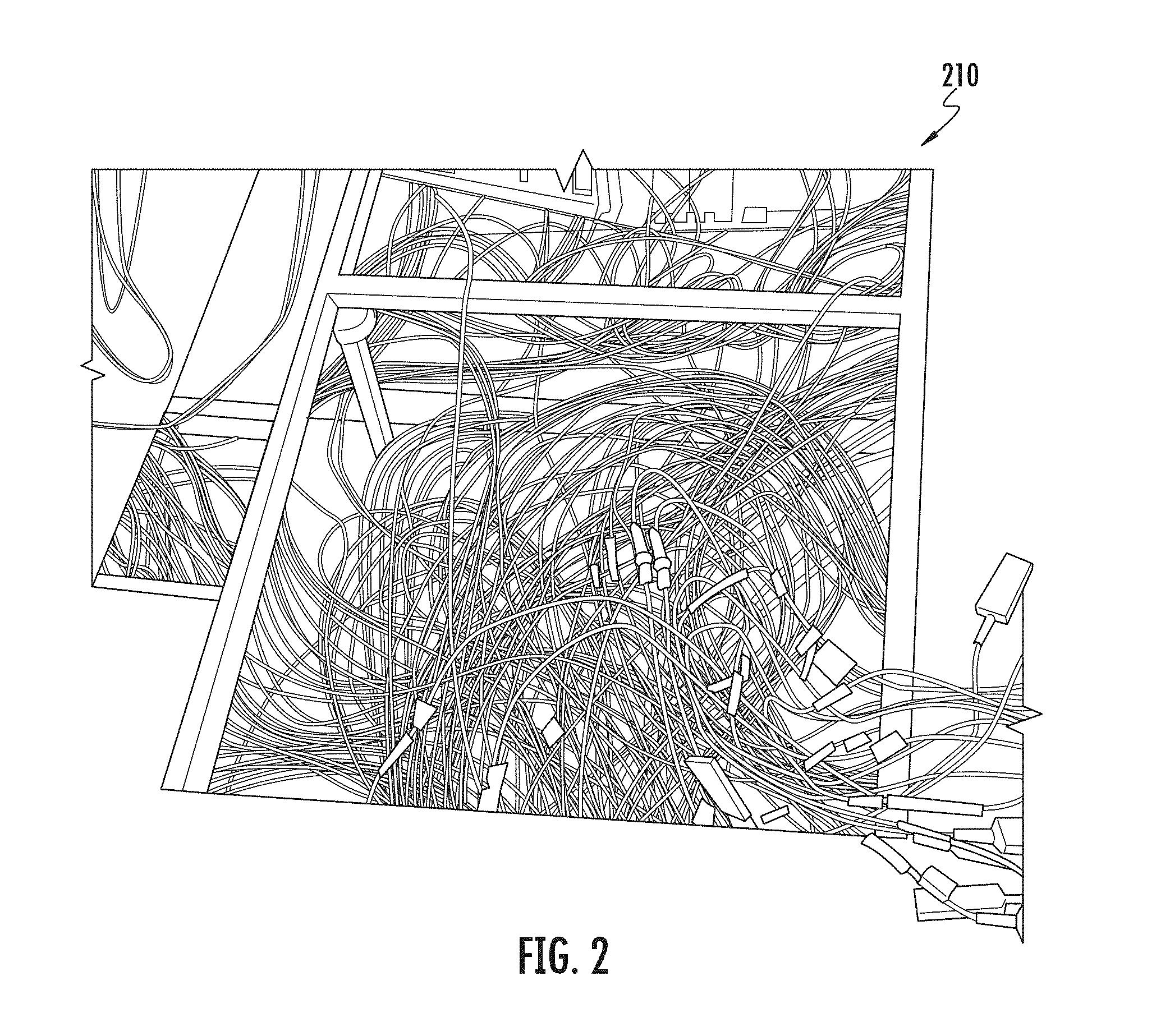
FIG. 2 is a perspective view of an under-floor cable tray supporting patch cords.
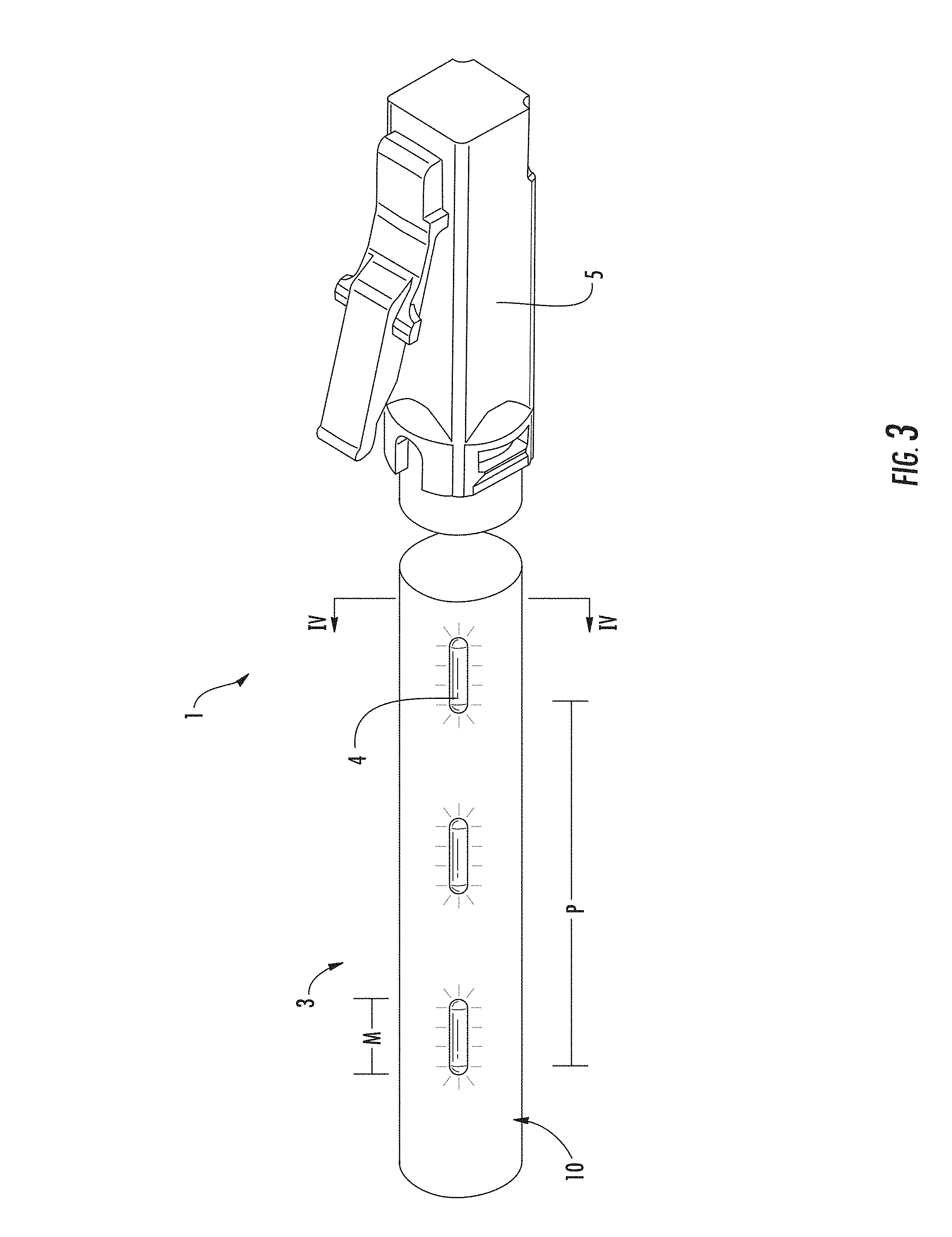
FIG. 3 is a side view, partially in cross-section, of a portion of a traceable cable assembly according to one embodiment.
FIG. 4 is a cross-sectional view of the cable assembly of FIG. 3 along the plane IV-IV.
FIG. 5 is a lengthwise cross sectional view of a tracer element of the cable assembly according to embodiments of the present disclosure.
FIG. 6 is a schematic view of light propagating through and being scattered from the tracer element of FIG. 5.
FIG. 7 shows a method of forming a side-emitting optical fiber as the tracer element of FIG. 5.
FIG. 8 shows example scattering sites of the side-emitting optical fiber as viewed under a microscope.
DETAILED DESCRIPTION
Various embodiments will be further clarified by examples in the description below. In general, the description relates to side-emitting waveguides, cables, and cable assemblies using the waveguides to facilitate the traceability of the cable or cable assembly. This description also relates to methods of forming the side-emitting waveguides, cables and cable assemblies.
A problem that occurs in data centers or similar network locations is congestion and clutter caused by large quantities of cables. FIG. 1 shows an example of congestion in an equipment rack 110. FIG. 2 shows congestion in an under-floor cable tray 210. Network operators frequently desire to change connections to accommodate moves, adds, and changes in the network. However, such congestion makes it difficult to trace a particular cable from the source to the receiver, which may be required to perform the moves, adds, and changes in the network.
An aspect of this disclosure is the provision of side-emitting waveguides, usable within traceable cables, which provide efficient light emission that may provide visibility of the waveguide in well-lit rooms over a significant distance, wherein the waveguides may be produced by an efficient manufacturing method.
Turning back to the figures, FIG. 3 shows a cable assembly 1 with improved tracing capabilities according to embodiments of the present disclosure. The cable assembly 1 includes a cable 3, tracer locations 4, and a connector 5. Although not shown, it should be understood that a connector 5 may be present on each opposite end of the cable 3 to allow the cable assembly 1 to act as a patch cord between components of a network. The connector 5 may vary widely depending on the nature of the cable 3 and the components being connected. The specific connector 5 selected should match the port configuration of the network component and will vary based upon the quantity and type of signals being transmitted by the cable 3. The distance between the connectors 5 may define a length for the cable 3. Cables 3 of the present disclosure are not specifically limited in their length, however, the cables 3 may have a length of at least about 1 meter and up to several tens of meters, such as one-hundred meters.
FIG. 4 shows a cross section of the cable 3 to represent one possible embodiment. The cable 3 may include one or more data transmission elements 7. Two such data transmission elements 7 are shown. The data transmission elements 7 may be of the same type or different types as compared to one another. Generally, a data transmission element 7 is a structure capable of carrying a data signal from one end of the cable 3 to the other. The data transmission element 7 may be configured to transmit an electrical signal, for example, using a copper wire or other electrically conductive material. Alternatively, or in addition, the data transmission element 7 may be configured to transmit an optical signal by conducting electromagnetic waves such as ultraviolet, infrared, or visible light to carry data from one location to another.
In some embodiments, the cable 3 may be more appropriately referred to as a conduit, without having any data transmission elements 7. Instead of transmitting a data signal, these cables 3 may transmit fluids such as air or liquid. These cables 3 may be appropriate for use in a medical setting such as IV lines or oxygen tubing. The cable 3 includes a jacket 10. The jacket 10 may be a hollow tube forming a conduit that can substantially surround the data transmission elements 7 and that can define an outer surface of the cable 3. Alternatively, the data transmission elements 7 may be at least partially embedded within the jacket 10.
Cables 3 of the present disclosure include a tracer element 15. The tracer element 15 is provided to enable the cable 3 to be selectively identified at one or more areas along the cable 3. The tracer element 15 may be visually identified with or without special equipment, such as an IR camera.
One example of a tracer element 15 is a side-emitting optical fiber 20 used to identify one or more portions of the cable 3. The side-emitting optical fiber 20 may be referred to interchangeably as a side-emitting optical waveguide herein. Therefore this disclosure does not intend to differentiate between the terms "optical fiber" and "optical waveguide" per se. The side-emitting optical fiber 20 may conduct nonvisible light. The side-emitting optical fiber 20 can also be used to conduct visible light, such as green light at approximately 532 nm. Red light, blue light, or a combination thereof could also be used to assist with tracing the cable 3. Green light may be used due to the relative high degree of sensitivity of the human eye to green light.
As seen in FIG. 4, the side-emitting optical fiber 20 is embedded within a portion of the jacket 10. In alternative embodiments, the side-emitting optical fiber 20 could be adjacent to the data transmission elements 7 inside a cavity formed by the jacket 10. If the side-emitting optical fiber 20 is within such a cavity, the jacket 10 may have at least some areas that are highly transparent. In yet other embodiments, the side-emitting optical fiber 20 could be provided on or mounted to the outside of the jacket 10.
Still referring to FIG. 4, the jacket 10 may include a pigmented portion 22 and an un-pigmented portion 24. The pigment used in the pigmented portion 22 may be selected to identify the nature of the cable 3 to one of ordinary skill in the art, based on the number, type, and arrangement of data transmission elements 7 therein. The side-emitting optical fiber 20 may be embedded within the un-pigmented portion 24. The un-pigmented portion 24 may include some pigment, but is typically more optically transparent than the pigmented portion 22. Therefore by locating the side-emitting optical fiber 20 within the un-pigmented portion 24, any light scattered from the side-emitting optical fiber 20 will be more visible.
Turning to FIG. 5, the side-emitting optical fiber 20 includes at least a core 30 and a cladding 32. The core 30 may be made from glass, particularly silica-based glass, having a first index of refraction. Alternatively, the core 30 may be formed from a polymer. The size of the core 30 is not particularly limited, but in some embodiments diameters may be between and including about 100 microns and about 250 microns. The core may be, for example, 125 microns. Cores that are significantly smaller may be subject to damage from handling, and cores that are significantly larger may be subject to damage when bending.
In some embodiments, the core 30 may be a substantially solid core, generally free of voids or air pockets as found within the airline optical fiber type of diffusive optical fibers. A core 30 that is free from voids may facilitate splicing, polishing, or other processing operations, which may be needed in some embodiments to make ends of the side-emitting optical fiber 20 compatible with a device for launching light into the side-emitting optical fiber.
The cladding 32 can be a polymer, such as fluoro-acrylate. In the embodiment illustrated in the drawings, the material for the cladding 32 is selected to have an index of refraction that differs from the index of refraction of the core 30. In some embodiments the index of refraction of the cladding 32 is lower than that of the core. In some embodiments, the indices of refraction produce a step-index optical fiber. In other embodiments, the side-emitting optical fiber 20 may be a trapezium or triangular index fiber. The cladding 32 closely surrounds the core 30 to help maintain light within the side-emitting optical fiber 20. The cladding 32 may have a thickness between about 4% and about 40% of the diameter of the core. For example, the cladding 32 may be between about 5 and about 50 microns thick from the surface of the core 30 to an exterior surface 36 of the cladding 32 when the core 30 has a diameter of 125 microns.
According to embodiments of the present description, scattering sites 40 are selectively provided at spaced apart locations on the cladding 32 along the length of the side-emitting optical fiber 20. The scattering sites 40 are configured to provide areas where light, which is otherwise traveling along the side-emitting optical fiber 20, is scattered and therefore able to be emitted from the side of the side-emitting optical fiber 20, as shown in stippled lines in FIG. 6, to form the tracer locations 4 shown in FIG. 3.
The scattering sites 40 are areas where the exterior surface 36 is modified, removed, deformed, or damaged to produce optical surfaces tending to scatter incoming light. Some or all of the scattering sites 40 may be annular or otherwise generally ring shaped, extending around the entire circumference of the side-emitting optical fiber 20. In some embodiments, as understood from FIG. 6, each scattering site 40 does not extend around the full circumference of the side-emitting optical fiber 20. The scattering sites 40 may sweep an arc approximately 180 degrees, 90 degrees, or even less around the circumference.
A complete ring shape may provide the most uniformly scattered light, but a full ring is not believed necessary to have light scatter in all 360 degrees around a lengthwise axis of the side-emitting optical fiber 20 and/or light to be seen 360 degrees a lengthwise axis of the cable 3. The scattering sites 40 scatter light generally in all directions with varying intensity. Therefore, each scattering site 40 directs light immediately out of an adjacent portion of the exterior surface 36, and also directs light back through the core 30 and out an opposite portion of the exterior surface 36 as schematically illustrated in FIG. 6. Scattering light from the side-emitting optical fiber 20 about 360 degrees can be desired to avoid directionality in the side-emitting optical fiber 20. Directionality may require more precise orientation of the side-emitting optical fiber 20 with the jacket 10 and cable 3. If the side-emitting optical fiber 20 emitted light in to a particular direction, that emission direction may need to be oriented toward the exterior of the cable 3 to be visible. Again, by scattering light 360 degrees around the side-emitting optical fiber 20, the side-emitting optical fiber allows the scattered light be to be seen from any viewpoint around the lengthwise axis of the cable 3.
The scattering sites 40 may be produced by a variety of mechanical, optical, or chemical processes. In the embodiment of FIG. 7, the scattering sites 40 are produced as the result of ablation caused by impact with high intensity light from a laser 76. The ablation process removes some of the cladding 32 and leaves behind an optically rough surface portion.
Several characteristics of the scattering sites 40 may be refined to help ensure that the extraction of light from the core 30 and cladding 32 to provide tracer locations 4 along the cable 3 are each visible in a well-lit environment. The characteristics may also be refined based the practical manufacturability of the cable 3 and side-emitting optical fiber 20.
First, the separation P between the scattering sites 40 may be selected to address the unique challenges associated with cable assemblies for data centers or similar network locations. In one embodiment, the scattering sites 40 should be at least about 1 cm apart and less than about 1 meter apart. Scattering sites 40 that are too close together approach a uniform emission along the length of the cable 3, and may lose the efficient use of light provided by the discrete tracer locations 4. Scattering sites 40 that are too far apart may lose the benefits of along-the-length tracer locations 4 and the ability to sufficiently trace the cable 3 in its environment with other cables. Additionally, scattering sites 40 that are too far apart may result in no scattering sites 40 sufficiently close to the terminal end of the cable 3 to provide a tracer location 4 within the appropriate equipment rack 110. An approximate separation P of about 10 cm may balance the light efficiency and traceability benefits, keeping in mind that several of the tracer locations 4 may be hidden behind other cables, effectively increasing the relative spacing between each tracer location 4. In some embodiments, the separation P may facilitate identifying the overall length of the cable 3. For example, the approximate separation P may be about 1 meter in some embodiments, thereby allowing a person to count the tracer locations 4 to approximate the total length of the cable 3 in meters. In other embodiments, the approximate separation P may be about 1 foot, thereby allowing a person to count the tracer locations 4 to estimate the total length of the cable 3 in feet.
As used herein, the cable 3 and the side-emitting optical fiber 20 may be described as each having respective launched ends and traced ends. The launched ends can be the known, accessible end of the cable 3 and end of the side-emitting optical fiber 20 where the network operator would provide (i.e. launch) tracer light to the side-emitting optical fiber 20. The respective traced ends should therefore be understood as the respective ends of the cable 3 and optical fiber 20 opposite the launched ends. The traced end, particularly of the cable 3, is the end of the cable that needs to be identified by the tracing process. It should be understood that these ends are not fixed. For any given operation, either end of the cable 3 may constitute the launched end and the traced end.
The size of each scattering site 40 may also be based on the challenges associated with cable assemblies for data centers or similar network locations. The size of each scattering site 40 may include the arc sweep around the side-emitting optical fiber 20. The size of each scattering site 40 may also include the magnitude M (FIG. 3) along the length of the side-emitting optical fiber 20 (i.e., "magnitude M" refers to the length of each scattering site measured parallel to the lengthwise axis of the side-emitting optical fiber 20). In some embodiments, the magnitude M may be between about 10 microns and about 50 mm, or even between about 0.5 mm and about 4 mm (such as about 2 mm for one specific example).
Further, the scattering sites 40 may be characterized by their depth D (FIG. 5) from the exterior surface 36 to a point closest to the core 30. One skilled in the art will appreciate that light traveling through the side-emitting optical fiber 20 may be described as forming a bell shaped distribution pattern relative to the central lengthwise axis of the core 30. The edges of the distribution, the part traveling through the cladding 32, may be referred to as the evanescent tail of the propagating light. It is this tail that is clipped by the scattering sites 40 and sent traveling in all directions. Therefore, the deeper each scattering site 40 penetrates into the cladding 32, the greater portion of the light distribution that is available for scattering by the scattering site 40. Therefore, selecting the depth D of each scattering site 40 balances the desire to scatter out a sufficient amount of light to be visible in a well-lit room with the desire to maintain enough light within the side-emitting optical fiber 20 to provide sufficient light to each of the scattering sites 40 downstream.
In an extreme example, the scattering sites 40 may remove the cladding 32 completely down to the core 30. In one example, the scattering sites 40 do not completely remove the cladding 32 at the given location. Depths D may include between about 1% to about 100% of the thickness of the cladding 32. Yet again, the depth D of each scattering site 40 may be substantially consistent along the length of the cable 3. Alternatively, the depth D may vary as a function of the distance from an end of the cable 3 or side-emitting optical fiber 20. For example the depth D may increase with distance from the launched end. The depth D is generally defined as a maximum distance toward the core 30 or a maximum percentage of cladding removal for any given scattering site 40. The process used, and resulting surface profile of each scattering site 40, is likely to render a range of depths for any given scattering site 40. In some embodiments, the range of depths may be minimized and essentially random. In other embodiments, the range of depths may be provided with a general profile, like the concave areas represented in FIGS. 5 and 6.
The side-emitting optical fiber 20 may include at least one coating 50 applied to the exterior surface 36 and scattering sites 40 of the cladding 32. The coating 50 may be between about 10 and about 70 microns thick. The coating 50 may be provided as a layer of protection for the core 30 and the cladding 32. The coating 50 should be at least translucent, if not fully transparent, in locations corresponding with the scattering sites 40. The coating 50 may have light transmission windows or have generally uniform light transmission characteristics. The coating 50 may be made from acrylate. The refractive index of the coating 50 may be 1.56 relative to the refractive index of the optical cladding 32 of 1.35.
The side-emitting optical fiber 20 may also include an ink layer 60 applied to the coating 50. The ink layer 60 may be selectively applied to locations corresponding with the scattering sites 40. Alternatively, the ink layer 60 may be uniformly applied to the coating 50. The ink layer 60 may have further scattering elements, such as titanium oxide spheres, configured to diffuse the light being emitted from the side-emitting optical fiber 20. The ink layer 60 is configured to provide each tracer location 4 with an approximate Lambertian distribution pattern.
The side-emitting optical fiber 20 of the present disclosure has been described for use in facilitating traceability of a cable 3. In some embodiments, the side-emitting optical fiber 20 may have uses independent of the cable 3. For example, the side-emitting optical fiber 20 may not be used for tracing at all, but may itself provide decorative or functional illumination or indication.
Side-emitting optical fibers 20 according to this disclosure may be manufactured according to a process schematically illustrated in FIG. 7. A core 30, such as a glass core may be fed, pulled, or drawn, or otherwise passed at typical telecom speeds through a first liquid die block 70. There, a cladding 32 is deposited or otherwise applied to the core 30. In one example, process for adding the cladding 32 may be a pultrusion process. The cladded core 33 may pass through a curing station 73 where the cladding 32 is at least partially cured. In one example, the curing station 73 may emit UV light from lamps or LEDs to rapidly, optically cure the cladding 32.
After the cladding 32 is at least partially cured, the scattering sites 40 may be created by ablating the exterior surface 36 with at least one high intensity light source, such as a laser 76 as the cladded core 33 is drawn past. Two or more light sources positioned around the core 30 may be provided to achieve the desired arc sweep for each scattering site 40. The high intensity light impacts the cladding 32 and forms the scattering sites 40 by vaporizing or burning off some of the cladding 32 while locally affecting other portions of the cladding 32 to produce the resulting locally roughened surface as shown in FIG. 8. The roughened surface may be described as having a series of defects or voids. It should be recognized that the scattering sites 40 will be at least as large as the wavelength of the laser 76. Using a less collimated beam emitted from slightly further from the cladded core 33 can produce scattering sites 40 that are wider radially. The laser 76 is also likely to cause a hot spot on the cladding 32 that spreads beyond the area directly in path with the light beam.
In one embodiment, each laser 76 is a CO2 laser, running at a repetition rate of 0.25 Hz to 100000 Hz with pulse energies of approximately 10000 W/s to 20000 W/s and pulse duration of 0.1 .mu.s to 10 seconds. As will be appreciated by one of ordinary skill in the art, other types of lasers, emitting other wavelengths of light, may be used. The repetition rate, pulse energy, and pulse duration may all be adjusted based on the draw rate of the cladded core 33 to achieve scattering sites 40 with the desired separation P, magnitude M, and depth D.
After the formation of the scattering sites 40 penetrating the exterior surface 36 of the cladding 32, the cladded core 33 may pass through a second liquid die block 80 where a similar pultrusion process may add a coating 50 over the ablated cladding. The coating 50 may be cured as it passing through a second curing station (not shown), or may be cured by other known means, such as temperature.
To provide a smoother, more Lambertian, light distribution pattern from the side-emitting optical fiber 20, a scattering ink layer 60 may be applied onto the coating 50 at a third liquid die block 84, or other processing unit, such as a spray applicator or printer.
In one embodiment, the side-emitting optical fiber 20 is manufactured on a single draw. As will be understood by those of skill in the art, the side-emitting optical fiber 20 can be produced in a continuous fashion on a single line, at a single location. Alternatively, it is possible that the side-emitting optical fibers 20 of the present description could also be produced by discrete steps at separate locations. For example, the core 30 may be wound up, transported between locations or manufacturing stations, and then run through the first liquid die block 70 for cladding. In another example, the scattering sites 40 may be created separate from the drawing of the cladded cores 33.
The side-emitting optical fibers 20 may continue on the single line directly to the manufacture of the cable 3. Alternatively, the side-emitting optical fiber 20 may be separately combined with the data transmission elements 7 and the jacket 10 in a different location or distinct time. In one embodiment, an extrusion or pultrusion process may be used to at least partially embed the side-emitting optical fiber 20 with the jacket 10 as the jacket 10 is being formed around the data transmission element 7. The side-emitting optical fiber 20 may be combined with at least one data transmission element 7 and a jacket 10 by a variety of processes known in the art, depending upon the particular type of cable 3 that is being manufactured.
Cable assemblies 1 may be made by cutting the cable 3 to a desired length and attaching the desired connectors 5 to each end according to processes known in the art, and dependent upon the type of cable assembly 1 being produced. For example, the connector 5 may be SC, LC, ST, FC, or MPO type connectors.
The side-emitting optical fibers 20, cables 3 that incorporate the side-emitting optical fibers 20, and cable assemblies 1 that incorporate the cables 3, each have several advantages that will be apparent to one of ordinary skill in the art. Particularly, use of a side-emitting optical fiber 20 within the cable 3 provides an improved ability for a network operator to quickly and efficiently trace a particular cable assembly 1 so that a traced end can be identified from a predetermined launched end of the cable assembly 1. The side-emitting optical fibers 20 of this disclosure can be configured to facilitate the ability to trace along the full length of the cable 3. This may be helpful to identify tangles or knots. This may also help when the particular equipment rack 110, in which the traced end is connected, is unknown. For example, equipment racks 110 often have front doors that are kept closed. Tracing along the length of the cable 3 may help identify which rack to search. If a tracer location 4 were only on the traced end the cable 3, it may be hidden behind the door.
While side-emitting optical fibers 20 according to this disclosure may provide tracer locations 4 along the length of a cable 3, they are usually not intended to provide continuous illumination along the length. As a result, the side-emitting optical fibers 20 are able to make more efficient use of a tracer source light. This means that tracer locations 4 can be provided along cables 3 of significant length, for example 30 m or more, while the tracer locations 4 may remain sufficiently bright to be readily visible in a well-lit room using a tracer source light of reasonable intensity.
A tracer light source may be integrated into the cable 3, or the connector 5, to illuminate the side-emitting optical fiber 20. In some embodiments, however, a separate tracer light source may be used to selectively emit light into the side-emitting optical fiber 20. By using a separate tracer light source, the cost of the cable 3 may be reduced compared to systems integrating a light source or using active light sources along the length to form the individual tracer locations 4.
In advantageous embodiments, the side-emitting optical fiber 20 can be made with a continuous manufacturing process where each step is performed on a single draw. Such a continuous process may provide a high rate of manufacture with minimum waste, transportation costs or labor costs. Use of laser ablation to form the scattering sites 40 provides a processing step that can be readily controlled in terms of pulse rate, pulse energy, and duration to finely tune the separation, arc sweep, and magnitude of the scattering sites 40 to achieve the best combination of traceability, brightness, and manufacturing efficiency.
Persons skilled in waveguide technology will appreciate additional variations and modifications of the devices and methods already described. Additionally, where a method claim below does not explicitly recite a step mentioned in the description above, it should not be assumed that the step is required by the claim. Furthermore, where a method claim below does not actually recite an order to be followed by its steps or an order is otherwise not required based on the claim language, it is not intended that any particular order be inferred.
The above examples are in no way intended to limit the scope of the present invention. It will be understood by those skilled in the art that while the present disclosure has been discussed above with reference to examples of embodiments, various additions, modifications and changes can be made thereto without departing from the spirit and scope of the invention as set forth in the claims.
* * * * *
References
D00000
D00001
D00002
D00003
D00004
D00005
D00006
D00007
D00008
XML
uspto.report is an independent third-party trademark research tool that is not affiliated, endorsed, or sponsored by the United States Patent and Trademark Office (USPTO) or any other governmental organization. The information provided by uspto.report is based on publicly available data at the time of writing and is intended for informational purposes only.
While we strive to provide accurate and up-to-date information, we do not guarantee the accuracy, completeness, reliability, or suitability of the information displayed on this site. The use of this site is at your own risk. Any reliance you place on such information is therefore strictly at your own risk.
All official trademark data, including owner information, should be verified by visiting the official USPTO website at www.uspto.gov. This site is not intended to replace professional legal advice and should not be used as a substitute for consulting with a legal professional who is knowledgeable about trademark law.