Recoil reducing stock system
Smith
U.S. patent number 10,228,213 [Application Number 15/898,884] was granted by the patent office on 2019-03-12 for recoil reducing stock system. This patent grant is currently assigned to Vista Outdoor Operations LLC. The grantee listed for this patent is Vista Outdoor Operations LLC. Invention is credited to Paul N. Smith.
| United States Patent | 10,228,213 |
| Smith | March 12, 2019 |
Recoil reducing stock system
Abstract
A recoil reduction system for a firearm. In some embodiments, the recoil reduction system includes a biasing element and a butt pad assembly configured to deform substantially proportionate to each other during a recoil event. The biasing element and/or butt pad assembly may include a spring-type element or, alternatively, a dampening device. The butt pad assembly may include an open cell butt pad having a hardness that is substantially higher than conventional butt pads.
| Inventors: | Smith; Paul N. (Bozeman, MT) | ||||||||||
|---|---|---|---|---|---|---|---|---|---|---|---|
| Applicant: |
|
||||||||||
| Assignee: | Vista Outdoor Operations LLC
(Farmington, UT) |
||||||||||
| Family ID: | 61257179 | ||||||||||
| Appl. No.: | 15/898,884 | ||||||||||
| Filed: | February 19, 2018 |
Related U.S. Patent Documents
| Application Number | Filing Date | Patent Number | Issue Date | ||
|---|---|---|---|---|---|
| 14996972 | Jan 15, 2016 | 9927206 | |||
| 62104549 | Jan 16, 2015 | ||||
| 62104573 | Jan 16, 2015 | ||||
| Current U.S. Class: | 1/1 |
| Current CPC Class: | F41C 23/06 (20130101); F41C 23/16 (20130101); F41C 23/08 (20130101); F41C 23/18 (20130101) |
| Current International Class: | F41C 23/08 (20060101); F41C 23/18 (20060101); F41C 23/16 (20060101) |
| Field of Search: | ;42/74 |
References Cited [Referenced By]
U.S. Patent Documents
| 1334467 | March 1920 | Moller |
| 1351141 | August 1920 | Thompson |
| 1842528 | January 1932 | Knight |
| 1964649 | June 1934 | Stetson |
| 2731753 | January 1956 | Mathieu |
| 2754608 | July 1956 | Stieffel, Jr. |
| 2831404 | April 1958 | Sampson et al. |
| 3001312 | September 1961 | Campbell |
| 3039222 | June 1962 | Hoge |
| 3105411 | October 1963 | Browning |
| 3176424 | April 1965 | Hoge |
| 3208180 | September 1965 | Woodcock |
| 3209482 | October 1965 | Kuzma et al. |
| 3233354 | February 1966 | Ahearn |
| 3405470 | October 1968 | Wesemann |
| 3492749 | February 1970 | Vironda |
| 3609903 | October 1971 | Pachmayr |
| 3707797 | January 1973 | Ruth |
| 3714726 | February 1973 | Braun |
| 3754344 | August 1973 | Spiliotis |
| 4112605 | September 1978 | Staub |
| 4439943 | April 1984 | Brakhage |
| H217 | February 1987 | Jorczak |
| 4663877 | May 1987 | Bragg |
| 4769937 | September 1988 | Gregory et al. |
| 4774873 | October 1988 | Shoales |
| 4785922 | November 1988 | Kiehart |
| 4867038 | September 1989 | Metz |
| 4910904 | March 1990 | Rose |
| 4956932 | September 1990 | Cupp |
| 4986018 | January 1991 | McDonald, Jr. |
| 5031348 | July 1991 | Carey |
| 5235764 | August 1993 | Perazzi |
| 5305539 | April 1994 | Von Kuster |
| 5343649 | September 1994 | Petrovich |
| 5362046 | November 1994 | Sims |
| 5375360 | December 1994 | Vatterott |
| 5392553 | February 1995 | Carey |
| 5410833 | May 1995 | Paterson |
| 5513730 | May 1996 | Petrovich et al. |
| D376188 | December 1996 | Riecken |
| 5598904 | February 1997 | Spyche, Jr. |
| 5634289 | June 1997 | Wascher |
| 5669168 | September 1997 | Perry |
| 5722195 | March 1998 | Bentley et al. |
| 5726377 | March 1998 | Harris et al. |
| 5827992 | October 1998 | Harris et al. |
| 5909002 | June 1999 | Atchisson |
| 5974718 | November 1999 | Bentley et al. |
| 5979098 | November 1999 | Griggs |
| 6164002 | December 2000 | Troncoso |
| 6305115 | October 2001 | Cook |
| 6467212 | October 2002 | Apel |
| 6481143 | November 2002 | McCarthy |
| 6530563 | March 2003 | Miller et al. |
| 6560911 | May 2003 | Sharp |
| 6564493 | May 2003 | Forman |
| 6594935 | July 2003 | Beretta |
| 6637141 | October 2003 | Weatherby et al. |
| 6651371 | November 2003 | Fitzpatrick et al. |
| 6662485 | December 2003 | Kay |
| 6684547 | February 2004 | Poff, Jr. |
| 6688031 | February 2004 | Steele |
| 6732466 | May 2004 | Bentley |
| 6758126 | July 2004 | Houtsma |
| 6761102 | July 2004 | Giza |
| 6834455 | December 2004 | Burigana |
| 6834456 | December 2004 | Murello |
| 6848351 | February 2005 | Davies |
| 6874267 | April 2005 | Fitzpatrick et al. |
| 6889461 | May 2005 | Vignaroli et al. |
| 6976333 | December 2005 | Sims |
| 7025052 | April 2006 | Schavone |
| 7055277 | June 2006 | Sims |
| 7121032 | October 2006 | Daul et al. |
| 7124529 | October 2006 | Havelka, Jr. |
| 7131367 | November 2006 | Boerschig et al. |
| 7152355 | December 2006 | Fitzpatrick et al. |
| 7152356 | December 2006 | Sims |
| 7162822 | January 2007 | Heayn et al. |
| 7273002 | September 2007 | Rogers |
| 7380487 | June 2008 | Mantas |
| 7478495 | January 2009 | Alzamora et al. |
| 7493845 | February 2009 | Mantas |
| 7536819 | May 2009 | Popikow |
| 7581954 | September 2009 | Schavone |
| 7673413 | March 2010 | Bentley |
| 7681351 | March 2010 | Bucholtz et al. |
| 7775150 | August 2010 | Hochstrate et al. |
| 7793453 | September 2010 | Sewell, Jr. et al. |
| 7823313 | November 2010 | Faifer |
| 7827722 | November 2010 | Davies |
| 7849626 | December 2010 | Fluhr |
| 7877917 | February 2011 | Cinciu |
| 7926216 | April 2011 | Bentley |
| 7930849 | April 2011 | Abraham et al. |
| 7938055 | May 2011 | Hochstrate et al. |
| 7963203 | June 2011 | Davies |
| 7966760 | June 2011 | Fitzpatrick et al. |
| 7984580 | July 2011 | Giauque et al. |
| 7992337 | August 2011 | Ochoa |
| 8037806 | October 2011 | Davies |
| 8051593 | November 2011 | Vesligaj |
| 8074391 | December 2011 | Petr j |
| 8117958 | February 2012 | Hochstrate et al. |
| 8127483 | March 2012 | Kincel |
| 8176668 | May 2012 | Simms et al. |
| 8176835 | May 2012 | Cottle |
| 8205371 | June 2012 | Cook et al. |
| 8286382 | October 2012 | Vesligaj |
| 8296984 | October 2012 | Kincel |
| 8296986 | October 2012 | Cook et al. |
| 8297175 | October 2012 | Davies |
| 8327569 | December 2012 | Kincel |
| 8341868 | January 2013 | Zusnnan |
| 8356542 | January 2013 | Cottle et al. |
| 8387297 | March 2013 | deBrun et al. |
| 8413361 | April 2013 | Quaedpeerds et al. |
| 8430015 | April 2013 | Faifer |
| 8434252 | May 2013 | Holmberg |
| 8448562 | May 2013 | Cottle |
| 8468729 | June 2013 | Sylvester |
| 8474169 | July 2013 | Cottle et al. |
| 8505226 | August 2013 | Vesligaj |
| 8505433 | August 2013 | Hochstrate et al. |
| 8555541 | October 2013 | Ingram |
| 8561338 | October 2013 | Chvala |
| 8607687 | December 2013 | Cottle |
| 8661963 | March 2014 | Patel |
| 8671608 | March 2014 | Vesligaj |
| 8677664 | March 2014 | Caravaggi et al. |
| 8677669 | March 2014 | Vesligaj |
| 8689672 | April 2014 | Cassels |
| 8707850 | April 2014 | Davies |
| 8720099 | May 2014 | Sisk |
| 8752472 | June 2014 | Lukman et al. |
| 8776421 | July 2014 | Vesligaj |
| 8782941 | July 2014 | Zusman |
| 8783160 | July 2014 | Hochstrate et al. |
| 8800189 | August 2014 | Fitzpatrick et al. |
| 8806791 | August 2014 | Cottle |
| 8815138 | August 2014 | Howe et al. |
| 8844185 | September 2014 | Jarboe |
| 8863428 | October 2014 | Vesligaj |
| 8904692 | December 2014 | Ballard |
| 8943726 | February 2015 | Kincel |
| 8950098 | February 2015 | Sims et al. |
| 9021727 | May 2015 | Butler |
| 2005/0246931 | November 2005 | Poff, Jr. |
| 2007/0089347 | April 2007 | Webber et al. |
| 2010/0229444 | September 2010 | Faifer |
| 2010/0251587 | October 2010 | Kincel |
| 2011/0113666 | May 2011 | Latimer |
| 2011/0138668 | June 2011 | Thomas |
| 2011/0258900 | October 2011 | Sims et al. |
| 2012/0167432 | July 2012 | Howe et al. |
| 2013/0174461 | July 2013 | Ballard |
| 2014/0165443 | June 2014 | Johnston |
| 2014/0196336 | July 2014 | Butler |
| 1122507 | Apr 1991 | EP | |||
| 1657518 | May 2006 | EP | |||
| 229306 | Nov 2012 | EP | |||
Other References
|
Givology [online] "The World's Largest Selection of Gun Parts & Accessories for Sale" First Accessed on Nov. 20, 2013. Retrieved from the Internet: http://www.gunaccessories.com/RecoilBuffers (15 pgs.). cited by applicant . Recoil Systems [online] "The ISIS II Recoil reducer is the only unit of its kind and is manufactured in the UK. The unit was developed and patented in 2001 and has sold very successfully through out the world since" First Accessed on Nov. 20, 2013. Retrieved from the Internet: http://www.recoilsystems.com/principle.asp (2 pgs.). cited by applicant. |
Primary Examiner: Johnson; Stephen
Attorney, Agent or Firm: Christensen, Fonder, Dardi & Herbert PLLC
Parent Case Text
CROSS-REFERENCE TO RELATED APPLICATIONS
This application is a Divisional of U.S. application Ser. No. 14/996,972, filed Jan. 15, 2016, now U.S. Pat. No. 9,927,206, which claims the benefit of U.S. provisional patent application No. 62/104,549, filed Jan. 16, 2015, and U.S. provisional patent application No. 62/104,573, filed Jan. 16, 2015, the disclosures of which are hereby incorporated by reference herein in their entirety.
Claims
What is claimed is:
1. A butt pad for a buttstock of a firearm, said butt pad comprising a lattice structure defining an open cell structure that is exposed to ambient air, said lattice structure defining a plurality of primary polygonal structures including a combination of perpendicular linkages and canted linkages joined at junctions, wherein said butt pad is formed of a material having a Shore A hardness of at least 50 and not more than 70.
2. The butt pad of claim 1, wherein: said primary polygonal structure defines a nominal internal length dimension in a direction parallel to an actuation axis of said firearm; said perpendicular linkages and said canted linkages each define a nominal thickness; and a ratio of said nominal internal length dimension to said nominal thickness is in a range of 3 to 4.5 inclusive.
3. The butt pad of claim 2, wherein said ratio is in a range of 3.7 to 3.8 inclusive.
4. The butt pad of claim 1, wherein: said butt pad defines a maximum length thickness in a direction parallel to an actuation axis of said firearm; said primary polygonal structure defines a nominal internal length dimension in a direction parallel to an actuation axis of said firearm; and a ratio of said maximum length thickness to said nominal internal length dimension is in a range of 2.5 to 4.5 inclusive.
5. The butt pad of claim 4, wherein said ratio is in a range of 3.3 to 3.7 inclusive.
6. The butt pad of claim 1, wherein said lattice structure defines a porosity of at least 85% and not more than 92%.
7. The butt pad of claim 1, wherein said primary polygonal structure is a hexagonal structure.
8. The butt pad of claim 7, wherein said primary polygonal structure defines a nominal internal length dimension in a direction parallel to an actuation axis of said firearm, said nominal internal length dimension being in a range of 0.4 inches to 0.55 inches inclusive.
9. The butt pad of claim 8, wherein said nominal internal length dimension is in a range of 0.1 inches to 0.15 inches inclusive.
10. The butt pad of claim 8, wherein said perpendicular linkages and said canted linkages each define a nominal thickness in a range of 0.032 inches to 0.25 inches inclusive.
11. The butt pad of claim 10, wherein said perpendicular linkages and said canted linkages each define a nominal thickness in a range of 0.1 inches to 0.15 inches inclusive.
Description
BACKGROUND
Recoil abatement systems are commonly employed in firearms, ranging from compliant butt pads to spring-loaded or shock dampening components coupled to the buttstock. More recent recoil abatement systems include "sliding stock" systems, featuring components internal to the buttstock that enable enables the receiver of the firearm to translate within the buttstock. Some stock systems, irrespective of whether they provide recoil abatement, feature the ability to readily adjust the overall length.
Conventional sliding stock systems can be limited in the amount of relative translation between the receiver and the buttstock, causing the buttstock to abruptly jolt the operator at the end of the recoil stroke.
In view of this shortcoming, improvements to sliding stock systems would be welcomed.
SUMMARY
Recoil reduction system concepts are disclosed that may be utilized with a variety of firearms, such as shot guns and rifles. In some embodiments, the recoil reduction systems are provided as retrofit kits for installation on existing firearms. In other embodiments, the recoil reduction systems are incorporated into factory-supplied firearms.
Various embodiments of the disclosed recoil reduction system provide dual deformable elements, a first of the deformable elements adapted to absorb a first fraction of a total recoil deflection without displacing the hand of the operator, and a second of the deformable elements adapted to absorb a second fraction of the total recoil deflection that does displace the hand of the operator. In bifurcating the total recoil deflection in this way, a hand grip of the recoil reduction system may be dimensioned to accommodate an ordinary hand size while providing a gradual, less jarring recoil to the shoulder of the operator.
Some conventional sliding stock systems include a pistol or hand grip and are arranged so that the receiver recoils into the pistol grip. An advantage of such systems is that, over the compensated stroke of the recoil, the pistol grip does not recoil into the hand of the operator, thereby providing greater stability and control of the firearm. However, this arrangement limits the length of the compensation of the recoil because the stroke cannot exceed the longitudinal dimension (i.e., the dimension along the x-axis of FIG. 1) of the pistol grip. At some point, simply enlarging the longitudinal dimension of the pistol grip to provide more slide length therein is not a solution because the enlarged dimension would cause the pistol grip to be too big for gripping with a normal sized hand. Accordingly, these systems do not fully accommodate recoil events that exceed the limited stroke length of the system. When these sliding stock systems reach the maximum stroke length, the remaining kinetic energy generates an impact shock that is absorbed by the operator. As a result, these systems can still cause the pistol grip to kick back against the hand of the operator for high powered loads, as well as against the shoulder of the operator.
To compensate, such sliding stock systems may include a conventional butt pad in an effort to at least mitigate the impact shock against the shoulder of the operator. However, such remedy are historically of marginal utility. Conventional butt pads are typically made of a compliant or soft material having a hardness typically in the range of 30 to 70 Shore 00 hardness. Such butt pads yield freely during the initial phases of the impact shock, but may become compressed and unyielding before the recoil stroke of a recoil event is complete, so that the operator will still experience a sudden impact shock.
Various embodiments of the disclosure are directed to abatement of the recoil beyond the stroke length of the sliding stock. To this end, the recoil reduction system includes a biasing element and a butt pad assembly configured to deform substantially proportionate to each other during a recoil event. This draws out the fraction of the recoil compensated by the butt pad over a longer time period, so that the operator experiences a less abrupt buildup of recoil force imparted by the butt pad against the shoulder and the handgrip against the hand. So, while the butt pad and handgrip will translate backward into the operator, such translation is comparatively gradual in relation to the more violent shock impact generated by conventional sliding stock systems.
In some embodiments, the biasing element and/or butt pad assembly includes a spring-type element or, alternatively, a dampening device. The butt pad assembly may include an open cell butt pad having a hardness that is substantially higher than conventional butt pads. In some embodiments, the recoil reduction includes a buffer tube housed within a buttstock, and a deformable structure for setting a clearance tolerance between the buffer tube and the buttstock to reduce lateral play while enabling smooth translation therebetween. In some embodiments, a guide pin and/or skid projections provide interference between the sliding components of the recoil reduction system when in a battery position, while releasing the interference during a recoil event.
In some embodiments, favorable performance of the butt pad assembly is realized by material and structural characteristics that linearize the deflection of the butt pad assembly over the time period of the recoil event by promoting rotation of the internal structural elements as opposed to compression of the internal structural elements. A surprising result of this philosophy is the use of harder rather than softer materials for the butt pad, which favors rotation of structural elements over compressive deformation of the structural elements. Favorable structural characteristics can be characterized in several ways, including the type of structure (e.g., various polygonal structures, relationship between linkages within that structure), a porosity of such structures, and dimensionless characteristics of the open cell structures. Favorable combinations of hardness and structure of the butt pad assembly can be more generally characterized by spring constant, compressive displacement, and/or energy capacity. Favorable characteristics of the overall may be characterized in terms of the spring constants and energy capacity of both the butt pad assembly and the sliding stock, as well as a ratio of the compressive displacements of the sliding member to the butt pad assembly.
Structurally, a recoil reduction system is disclosed that includes a buttstock, a slide member for coupling to a receiver, a biasing element operatively coupled with the buttstock and the slide member, and a butt pad coupled to a proximal end of the buttstock. In one embodiment, the biasing element is configured for a compressive displacement that is at least 1.5 times and not more than 5 times a compressive displacement of the butt pad during a recoil event.
A butt pad for a buttstock of a firearm is also disclosed, the butt pad including a lattice structure defining an open cell structure that is exposed to ambient air, the lattice structure defining a plurality of primary polygonal structures including a combination of perpendicular linkages and canted linkages joined at junctions. In one embodiment, the butt pad is formed of a material having a Shore A hardness of at least 50 and not more than 70.
BRIEF DESCRIPTION OF THE DRAWINGS
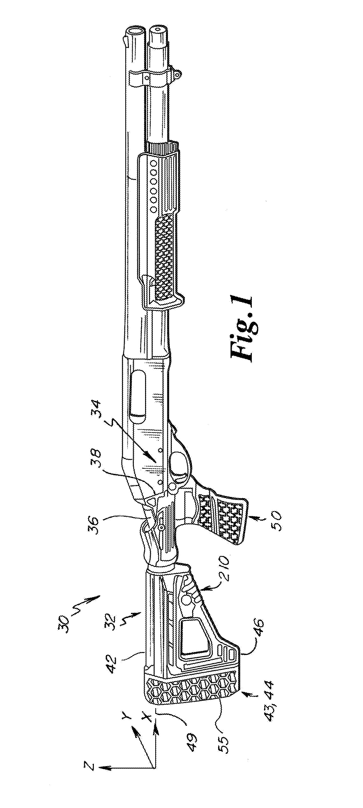
FIG. 1 is a perspective view of a modified firearm utilizing a recoil reduction system in an embodiment of the disclosure;
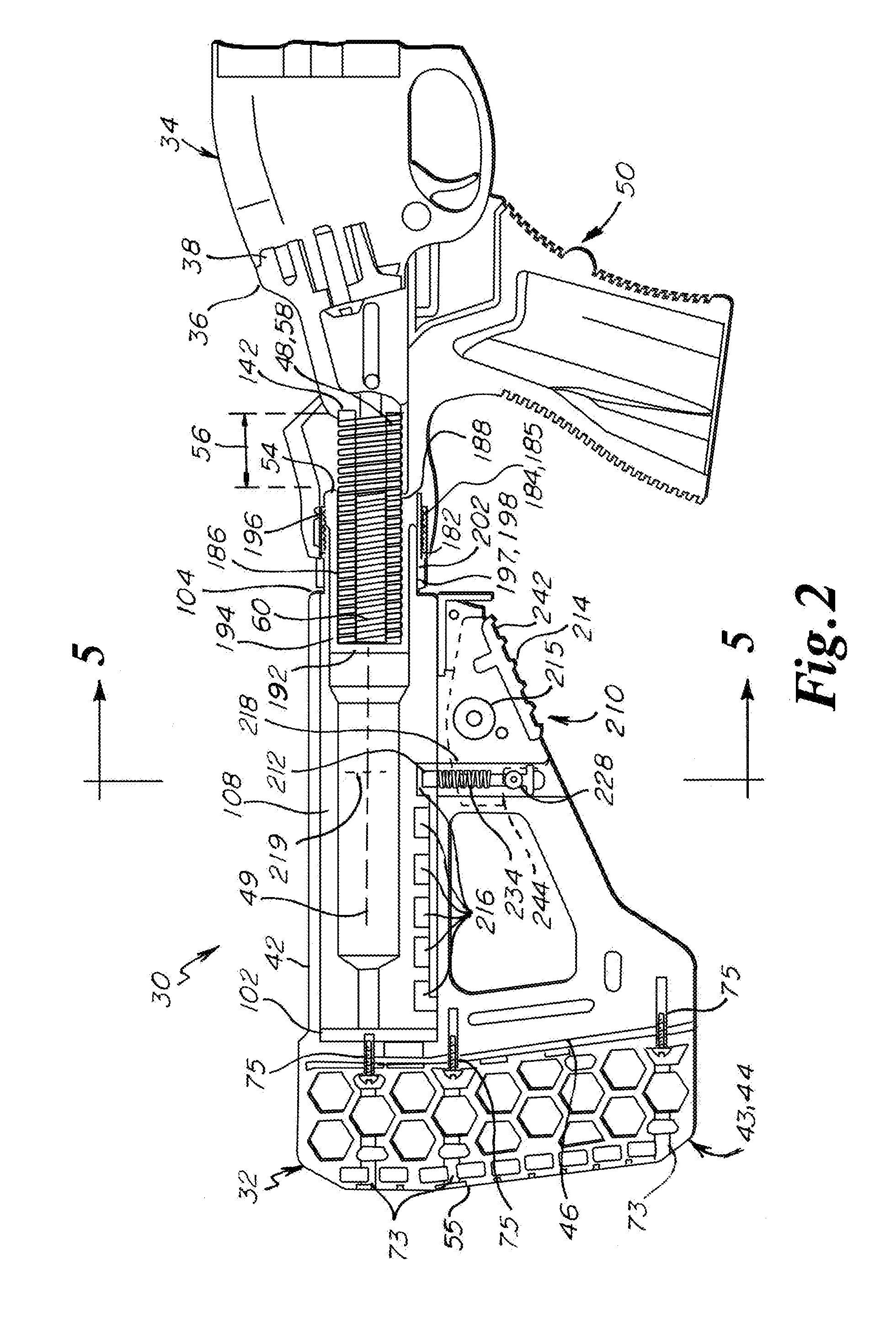
FIG. 2 is a sectional view of the recoil reduction system of FIG. 1 in a battery configuration in an embodiment of the disclosure;
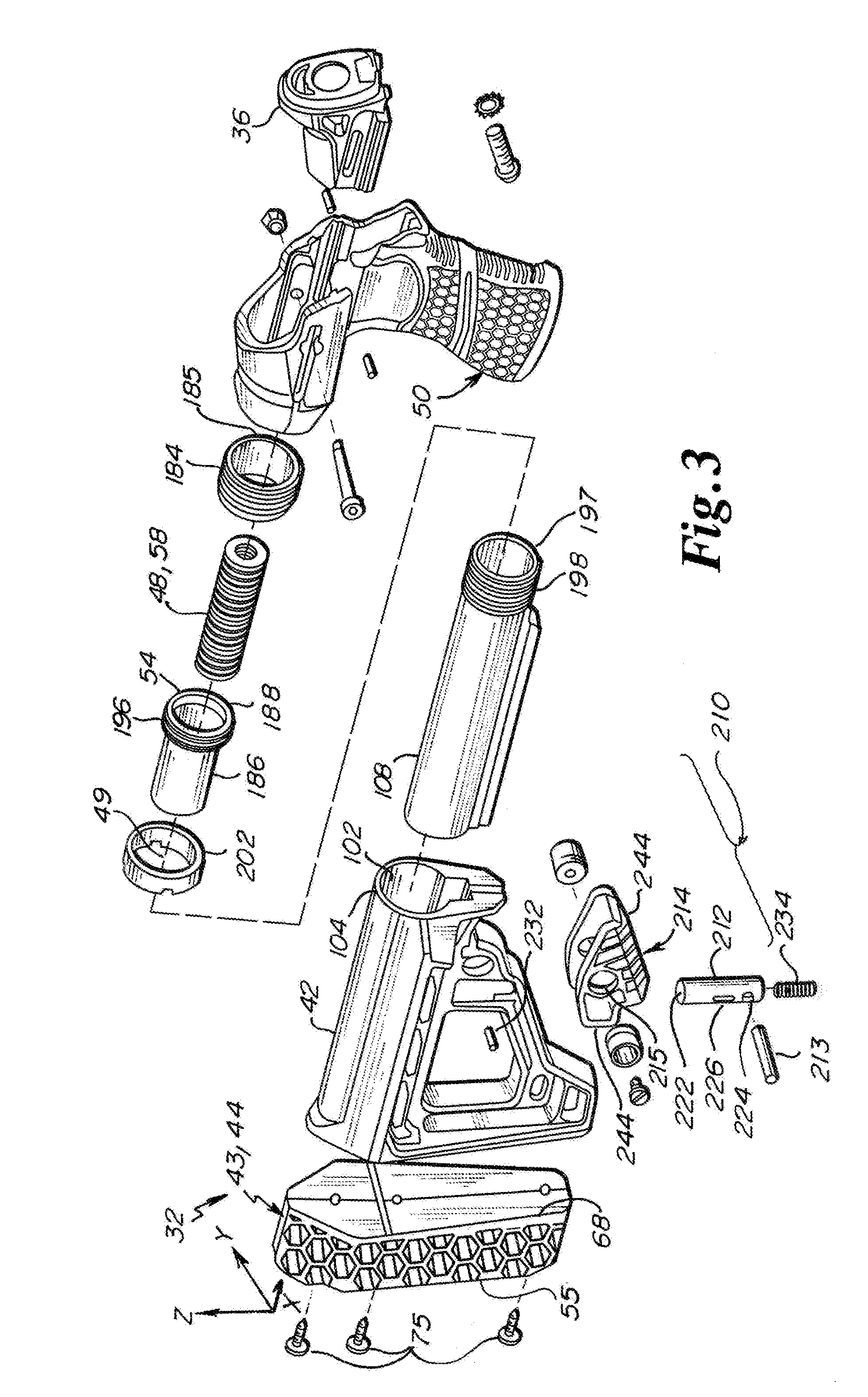
FIG. 3 is an exploded view of the recoil reduction system of FIG. 1 in an embodiment of the disclosure;
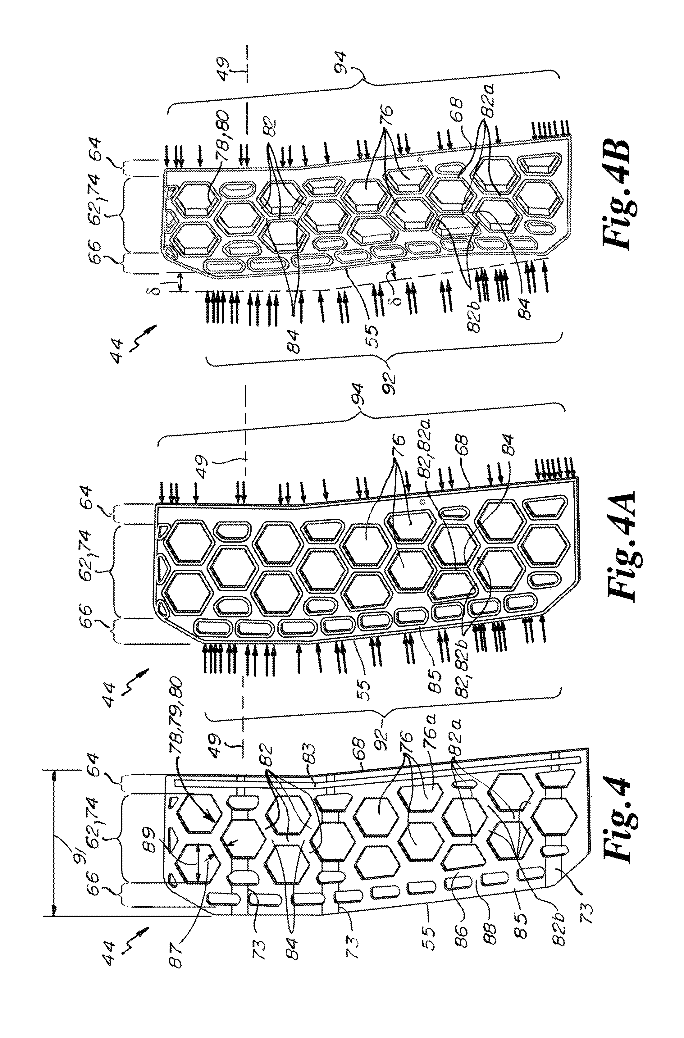
FIG. 4 is an elevation view of an open cell butt pad in an embodiment of the disclosure;
FIGS. 4A and 4B are elevation views of the open cell butt pad of FIG. 4 for a finite element analysis simulating a recoil event in an embodiment of the disclosure; and
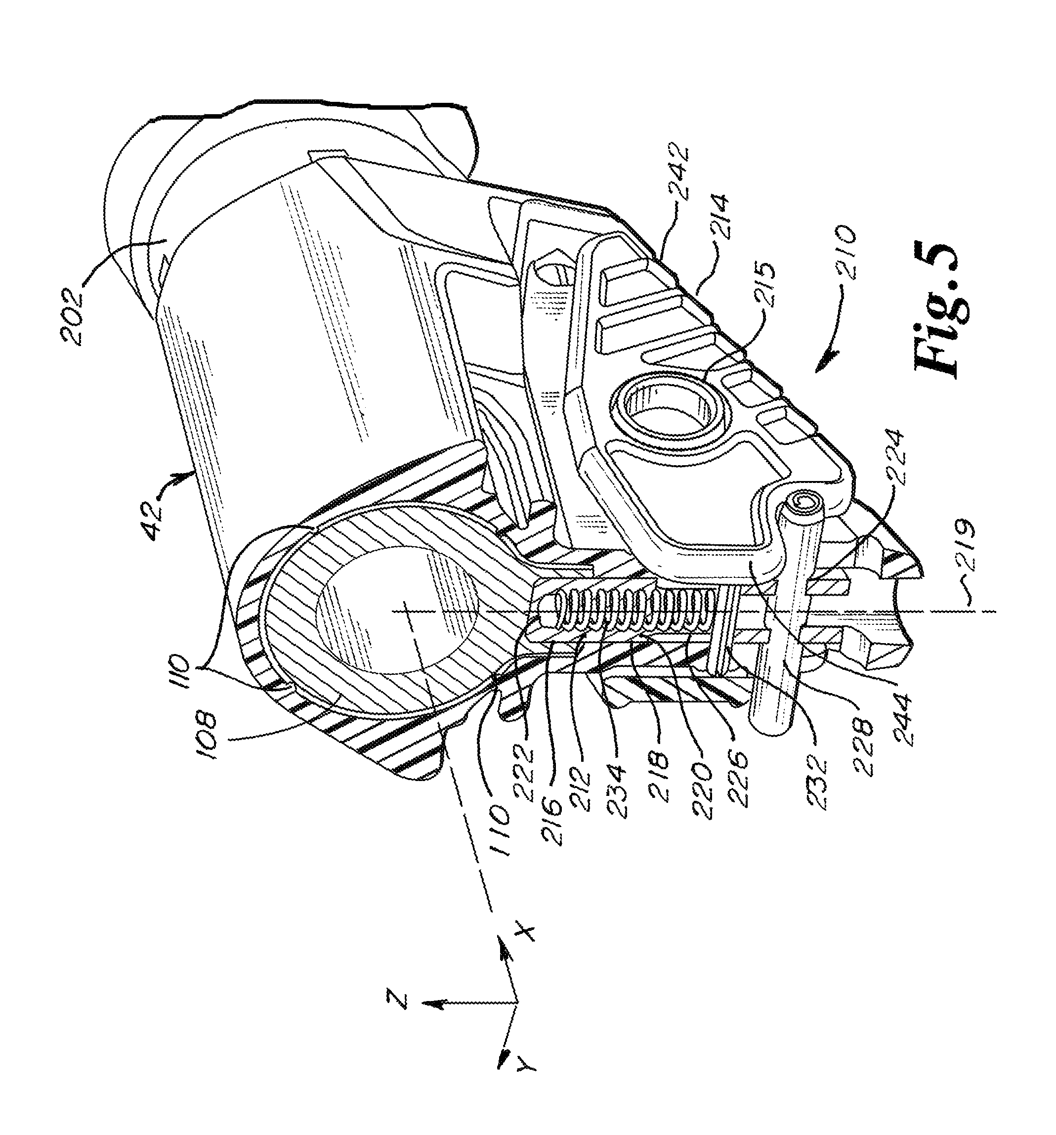
FIG. 5 is a partial sectional view of a stock length adjustment mechanism in an unactuated state in an embodiment of the disclosure.
DETAILED DESCRIPTION
Referring to FIG. 1, a modified firearm 30 implementing a recoil reduction system 32 is depicted in an embodiment of the disclosure. The firearm 30 includes a receiver 34 of a standard firearm, for example a Remington Model 870.TM. Wingmaster.RTM. (depicted). The recoil reduction system 32 includes a slide member 36 having a front or distal end 38 configured for mounting to the specific receiver 34 and operatively coupled to a buttstock 42. A butt pad assembly 43 is operatively coupled to a rear or proximal end 46 of the buttstock 38. In various embodiments, the butt pad assembly 43 includes an open cell butt pad 44, as depicted in FIG. 1.
A biasing element 48 (FIG. 2) is operatively coupled with the slide member 36 and the buttstock 42 to exert a biasing force therebetween, thereby urging the slide member 36 forward relative the buttstock 42. In one embodiment, the recoil reduction system 32 includes a hand grip assembly 50 mounted to the buttstock 42, the slide member 36 extending into the hand grip assembly 50 and being translatable along an actuation axis 49. In one embodiment, the biasing element 48 is housed in the hand grip assembly 50.
Referring to FIGS. 2 and 3, the recoil reduction system 32 is presented in an embodiment of the disclosure. In one embodiment, the recoil reduction system 32 includes a rearward or proximal stop 54 that limits the rearward or proximal travel of the slide member 36 relative to the buttstock 42 during firing of the modified firearm 30. (In the depicted embodiment, the proximal stop 54 is a distal end of a spring tube 186, described in greater detail below.) Herein, "proximal" refers to a relative direction or location that is towards a shouldered face 55 of the butt pad assembly 43, while "distal" refers to a relative direction or location that is away from the shouldered face 55.
A maximum bias member displacement 56 (FIG. 2) along the actuation axis 49 is thereby defined between the proximal stop 54 and the slide member 36 when in a battery configuration. In various embodiments, the biasing element 48 is configured for a substantially linear spring rate over the maximum bias member displacement 56. In various embodiments, the spring rate is in the range of 120 to 200 lbf/in inclusive. (Herein, a range that is said to be "inclusive" includes the end point values of the stated range, as well as the values between the end point values.) In some embodiments, the spring rate is in the range of 150 to 170 lbf/in inclusive.
In various embodiments, the biasing element 48 comprises a coiled spring 58. In some embodiments, the biasing element 48 also includes a second spring 60 nested within the coiled spring 58. By nesting springs in this manner, the springs act in parallel, providing a stiffer combined spring rate than either one of the springs 58, 60. In one non-limiting example, the coiled spring 58 is an ISO-204 die spring type having a spring rate of 25 N/mm and the second spring 60 is an ISO-203 die spring type having a spring rate of approximately 3.2 N/mm, for a combined spring rate of approximately 28 N/mm. Such springs are commercially available from, for example, Associated Spring Raymond of Maumee, Ohio, U.S.A. The coil spring(s) 58, 60 may be made of any suitable material available to the artisan, including carbon steel or a high resilience polymer. In other embodiments, the biasing element 48 includes some other suitably elastic member, such as a rubber cylinder (not depicted).
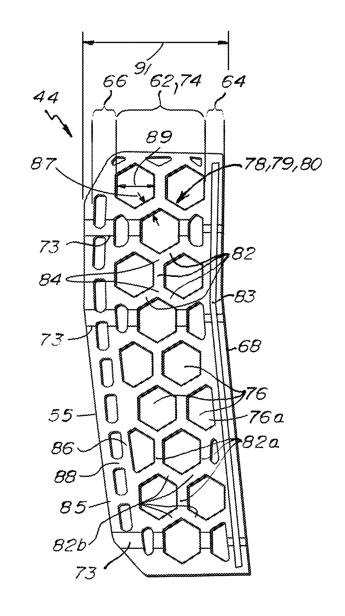
Referring to FIG. 4, the open cell butt pad 44 is depicted in isolation in an embodiment of the disclosure. In the depicted embodiment, the open cell butt pad 44 includes a core portion 62 that separates a mounting structure 64 and an end cap portion 66. The mounting structure 64 defines a distal face 68 of the open cell butt pad 44. The end cap portion 66 is disposed at the shouldered face 55 (proximal face) of the open cell butt pad 44 for registration against the shoulder or other anatomical component of an operator of the modified firearm 30. The open cell butt pad 44 may also define one or more access passages 73 to accommodate the passage of fasteners 75 (FIG. 2) for mounting of the open cell butt pad 44 to the buttstock 42.
The core portion 62 is an open cell structure 74 that defines a plurality of open cells 76 that are exposed to ambient air. That is, each of the open cells 76 of the open cell structure 74 is vented to ambient, for example by the absence of an exterior lateral skin, such that the open cell structure 74 defines a plurality of through-holes. In various embodiments, the open cells 76 extend laterally through the core portion 62 ("lateral" meaning parallel to any plane that is normal to the actuation axis 49).
The open cell butt pad 44 can be characterized as having a porosity or void fraction, defined as the ratio of the volume of the air that occupies the open cells 76 of the open cell butt pad 44 to the total volume of the open cell butt pad 44. In various embodiments, the porosity is in the range of 86% to 90% inclusive. In some embodiments, the porosity is in the range of 85% to 92% inclusive. In still other embodiments, the porosity is in the range of 80% to 95% inclusive.
In various embodiments, the open cell structure is defined by a lattice structure 78. The lattice structure 78 can be characterized as a network of linkages 82 joined at junctions 84, the linkages 82 and junctions 84 being unitary. In some embodiments, the lattice structure 78 defines a "honeycomb" structure 79, i.e., where the open cells 76 define at least part of a primary polygonal structure, as depicted in FIG. 4A. That is, some passages fully define the primary polygonal structure, while others, being interrupted by the boundaries of the open cell butt pad 44, form only a portion of the primary polygonal structure (e.g., open cell 76a of FIG. 4). In the depicted embodiment, the primary polygonal structure of the open cells 76 of the honeycomb structure 79 is a hexagonal structure 80. Other polygonal structures include triangular, diamond-shaped, pentagons, and octagons. In various embodiments, the lattice structure 78 is formed of a material having a Shore A hardness in the range of 55 to 65 inclusive. In some embodiments, the Shore A hardness is in the range of 50 to 70 inclusive. In still other embodiments, the Shore A hardness is in the range of 50 to 80 inclusive.
The mounting structure 64 of the open cell butt pad 44 may be profiled to complement the proximal end 46 of the buttstock 42. In one embodiment, the mounting structure 64 includes a plate 83 that is substantially rigid relative to the material of the open cell butt pad 44. The end cap portion 66 may be unitary or integrally formed with the lattice structure 78 of the core portion 62. In one embodiment, the end cap portion 66 includes a proximal plate portion 85 and a distal plate portion 86 separated by a plurality of web portions 88, the plate portions 85, 86 and web portions 88 being of the same material and hardness as the core portion 62.
For the hexagonal structure 80 of the depicted open cell butt pad 44, the linkages 82 fall into two general categories: perpendicular linkages 82a, which extend substantially perpendicular to the actuation axis 49 between junctions 84; and canted linkages 82b, which extend at acute angles relative to the actuation axis 49 between junctions 84. A third category of linkages are parallel linkages that extend substantially parallel to the actuation axis 49. While the hexagonal structure 80 does not provide examples of parallel linkages, the web portions 88 approximate such parallel linkages between the proximal and distal plate portions 84 and 86.
In certain embodiments, the primary polygonal structure of the open cells 76 of the lattice structure 78 define an internal dimension 89 in the longitudinal directions of the primary polygonal structure that is nominally 0.47 inches. In various embodiments, the internal dimension 89 is in a range of 0.45 inches to 0.5 inches inclusive; in some embodiments, in a range of 0.4 inches to 0.55 inches inclusive. In some embodiments, a nominal thickness 87 of the linkages 82 that define the primary polygonal structure is nominally 0.125 inches. In some embodiments, the nominal thickness 87 is in a range of 0.1 inches to 0.15 inches inclusive; in some embodiments, in a range of 0.063 inches to 0.188 inches inclusive; in some embodiments, in a range of 0.032 inches to 0.25 inches inclusive.
In various embodiments, open cells 76 of the lattice structure 78 can be characterized dimensionlessly by a void-to-thickness ratio, defined as the ratio of the internal dimension 89 in the longitudinal directions of the primary polygonal structure to the nominal thickness 87 of the linkages 82 that define the primary polygonal structure. In some embodiments, the void-to-thickness ratio is in the range of 3.0 to 4.5 inclusive; in some embodiments, in the range of 3.5 to 4.0 inclusive; in some embodiments, in the range of 3.7 to 3.8 inclusive.
In some embodiments, the open cells 76 can be characterized dimensionlessly as a length-to-void ratio, defined as the ratio of the a maximum length thickness 91 of the open cell butt pad 44 in the longitudinal directions to the internal dimension 87 in the longitudinal directions of the primary polygonal structure. In some embodiments, the length-to-void ratio is in the range of 2.5 to 4.5 inclusive; in some embodiments, in the range of 3.0 to 4.0 inclusive; in some embodiments, in a range of 3.3 to 3.7 inclusive; in some embodiments, in the range of 3.4 to 3.6 inclusive.
Referring to FIGS. 4A and 4B, depictions of the open cell butt pad 44 in operation are presented in an uncompressed and a partially compressed state, respectively, in an embodiment of the disclosure. The depictions of FIGS. 4A and 4B visually represent the results of a finite element analysis (FEA) model. A proximal boundary condition 92 emulating the interaction of an operator is imposed on the shouldered face or proximal face 55 of the end cap portion 66, and a distal boundary condition 94 emulating coupling with the buttstock 42 is imposed on the distal face 68 of the open cell butt pad 44. For the depicted embodiment, the open cells 76 of the open cell structure 74 extend side-to-side (i.e., parallel to the y-axis of FIG. 1). It is noted that the open cells 76 may extend in any direction lateral to the actuation axis 49 with similar effect (i.e., in any direction parallel to the y-z plane of FIG. 1).
For the FEA analysis, arbitrary force of 10 N was modeled to create a deformation profile. For illustrative purposes, the deformations were amplified 100-fold to arrive at the depiction of FIG. 4B. While some bending deformation of the linkages 82 is evident, the primary mode of the overall deformation of the hexagonal structure 80 is rotation of the linkages 82 about the junctions 84 of the lattice structure 78. Most of the perpendicular linkages 82a remain substantially perpendicular, with exceptions being those linkages 82a aligned with the discontinuity of the proximal boundary condition 92 relative to the distal boundary condition 94. The canted linkages 82b rotate substantially about their respective junctions 84.
Functionally, the effect is to produce an elongation of the open cells 76 of the hexagonal structure 80 in a lateral direction. In this way, the open cell butt pad 44 undergoes a nominal compression 6 (FIG. 4B) without substantial compression of the material that comprises the lattice structure 78. The rotation of the linkages and elongation of the open cells mitigates the non-linearity and attendant shock abruptness of the compressible materials of certain conventional butt pads.
As a system, when the modified firearm 30 is fired, the receiver 34 and slide member 36 recoil to produce simultaneous deformations of the biasing element 48 and the butt pad assembly 43, wherein the deformation of the biasing element 48 and the butt pad assembly 43 are substantially proportionate to each other throughout a recoil event. Herein, a "recoil event" is a recoil of the recoil reduction system caused by discharge of the connected firearm. The recoil event is further characterized as having a "recoil stroke" during which the biasing element 48 and the butt pad assembly 43 undergo increasing compression from a battery configuration to a maximum compressed state for the recoil stroke, and a "return stroke" during which the biasing element 48 and the butt pad assembly 43 undergo increasing expansion from the a maximum compressed state in returning to the battery configuration.
By maintaining the linearity of the compression of the butt pad 44 (or more generally, the butt pad assembly 43) throughout the recoil event, the recoil force imparted by the butt pad against the shoulder and by the handgrip against the hand extended over the entire time interval of the recoil stroke of the recoil event, as opposed to a more abrupt recoil force that is experienced by compression and subsequent structural collapse of softer, conventional butt pads.
In operation, during a recoil event, the slide member 36 is thrust against the biasing element 48 which exerts a recoil force against the buttstock 42. Typical and non-limiting impulse forces generated by conventional firearms range from 500 N to 2500 N (112 lbf to 560 lbf). Some of the recoil force is absorbed by (i.e., causes deformation of) the biasing element 48, whereas some of the recoil force is absorbed by the open cell butt pad 44. The deformation of the biasing element 48 and the open cell butt pad 44 can each be characterized in terms of compressive displacement parallel to the actuation axis 49. In various embodiments, the biasing element 48 is adapted for a compressive displacement that is at least 1.5 times and not more than 5 times a compressive displacement of the open cell butt pad 44 during firing of the modified firearm 30. In one embodiment, the biasing element 48 is adapted for a compressive displacement that is at least 2 times and not more than 4 times a compressive displacement of the open cell butt pad 44 during firing of the modified firearm 30. In one embodiment, the open cell butt pad 44 is adapted for a compressive displacement that is at least 8 mm and not more than 20 mm.
The biasing element 48 and the open cell butt pad 44 can also be characterized in terms of their respective spring rates. That is, biasing element 48 can be said to have a first spring rate, and the open cell butt pad 44 can be said to have a second spring rate. Herein, a "spring rate," also known as a "spring constant," of a component is defined by a ratio of the force to the compressive displacement of the component caused by application of that force, in accordance with Hooke's law.
In still other embodiments, one or both of the biasing element 48 and the open cell butt pad 44 is a dampening device (not depicted), such as a hydraulic damper or a pneumatic damper. Dampening devices are generally not characterized in terms of a spring rate, but rather in terms of an "energy capacity," having units of energy (e.g., joules or ft-lbf). A compressive displacement of such dampening devices during a recoil event can be calculated, such that the dampening device is sized to provide a desired compressive displacement. Herein, a "compressive displacement" is the change in length of a compressed component, such as the biasing member 48 or the open cell butt pad 44, in a direction parallel to the actuation axis 49 of the respective component during a recoil event. In various embodiments, the biasing element 48 is a dampening device having an energy capacity in the range of 30 to 100 Joules inclusive to provide a compressive displacement in the range of approximately 10 to 30 mm, depending on the impulse force.
The butt pad assembly 43 is not limited to the open cell butt pad 44. That is, a "butt pad" is a generic term for any structure that is affixed to the proximal end 46 of the buttstock 42. Alternative butt pads to the open cell butt pad 44 include, but are not limited to, coil-spring loaded plates and gel cores. Such alternative butt pads may be engineered to possess the displacement characteristics of the open cell butt pad 44 and to work in cooperation with the biasing element 48 to provide the same recoil effect as the disclosed embodiments.
In the depicted embodiment, the buttstock 42 defines a longitudinal bore 102 that extends along the actuation axis 49 and is accessible from a distal end 104 (FIG. 2) of the buttstock 42. In the depicted embodiment, a buffer tube 108 is disposed within the longitudinal bore 102. Herein, "longitudinal" is defined as being in a direction that is parallel to the actuation axis 49, whereas "lateral" is defined as being in any direction that is perpendicular to the actuation axis 49.
In further reference to FIGS. 2 and 3, the hand grip assembly 50 further defines a rearward opening 182. In one embodiment, a threaded insert 184 including internal threads 185 is molded into the rearward opening 182 of the hand grip assembly 50. In one embodiment, a spring tube 186 is disposed in the threaded insert 184, the spring tube 186 having an open forward end 188 and a bearing structure 192 at a rearward end 194. The bearing structure 192 may be, for example, an internal lip or flange, or a bridging structure such as a closed end (as depicted) or one or more laterally-extending rods. In the depicted embodiment, the forward end 188 includes exterior threads 196 that threadably engage with the threaded insert 184. The biasing element 48 is disposed in the spring tube 186 and extends into the rearward portion of the hand grip assembly 50, the biasing element 48 engaging both the bearing structure 192 of the spring tube 186 and a rearward face 142 of the slide member 36.
A front end portion 197 of the buffer tube 108 includes external threads 198 that mate with the internal threads 185 of the threaded insert 184 of the hand grip assembly 50. A castle nut 202 also engages the external threads 198 of the buffer tube 108, so that, when tightened against the hand grip assembly 50, the castle nut 202 imparts an axial load between the external threads 198 of the buffer tube 108 and the internal threads 185 of the threaded insert 184. During assembly, a bonding paste, such as LOCTITE.RTM., may be applied between the external threads 198 of the buffer tube 108 and the internal threads 185 of the threaded insert 184. The bonding paste and the axial force exerted by the castle nut 202 act to resist rotation between the buffer tube 108 and the hand grip assembly 50.
Referring to FIG. 5 and again to FIGS. 2 and 3, a stock length adjustment mechanism 210 for the recoil reduction system 32 is depicted in an embodiment of the disclosure. The stock length adjustment mechanism includes an adjustment pin 212, an adjustment lever 214 coupled to the buttstock 42 about a pivot 215, and a plurality of adjustment notches 216 (FIG. 2) formed on the buffer tube 108. Portions of the adjustment lever 214 are outlined in FIG. 2 in phantom. In one embodiment, the adjustment pin 212 is housed within a bore 218 defined in the buttstock 42, the bore 218 defining a pin actuation axis 219 that is parallel to the z-axis. The adjustment pin 212 and bore 218 are dimensioned so that the adjustment pin 212 can slide within the bore 218. In various embodiments, the adjustment pin 212 comprises a hollow tube 220 with a closed or restricted diameter end portion 222. The hollow tube 220 may define a circular through hole 224 and a slotted through hole 226.
In various embodiments, a cross pin 228 is disposed in the circular hole 224 of the adjustment pin 212, the cross pin 228 extending parallel to the y-axis. In some embodiments, an anchor pin 232 extends across the bore 218 and through the slotted through hole 226, the anchor pin 232 being perpendicular to the pin actuation axis 219 and oriented in a direction parallel to the y-axis. The anchor pin 232 is secured on both ends to the buttstock 42. In the depicted embodiment, as spring 234 is disposed in the hollow tube 220, captured between the end portion 222 and the anchor pin 232.
In the depicted embodiment, the bore 218 is aligned with a selected one of the plurality of adjustment notches 216, such that the adjustment pin 212 extends out of the bore 218 and into selected notch 216. In FIG. 2, the adjustment pin 212 is in the forward-most of the adjustment notches 216, so that the effective length of the recoil reduction system 32 is at its shortest.
In operation, to change the length adjustment of the recoil reduction system 32, a forward end 242 of the adjustment lever 214 is pressed toward the buttstock 42, causing the lever 214 to rotate about pivot 215 so that a rearward end 244 of the lever rotates away from the buttstock 42. The rotation causes the rearward end 244 of the adjustment lever 214 exerts a force on the cross pin 228 which transfers to the adjustment pin 212, so that the adjustment pin 212 becomes dislodged from the adjustment notch 216. With the adjustment pin 212 dislodged from the adjustment notch 216, the buffer tube 108 may be slid longitudinally within the bore 102 of the buttstock 42 to establish a different overall length of the recoil reduction system 32.
During actuation of the adjustment pin 212, the slotted through hole 226 slides over the stationary anchor pin 232 as the end portion 222 is drawn closer to the anchor pin 232. The spring 234 becomes compressed between the end portion 222 and the anchor pin 232. The compression biases the adjustment pin 212 so that, upon release of the adjustment lever 214, the adjustment pin 212 is urged back into contact with the buffer tube 108 and, perhaps after some additional positioning of the buffer tube 108 within the bore 102, into one of the adjustment notches 216.
References to "embodiment(s)", "disclosure", "present disclosure", "embodiment(s) of the disclosure", "disclosed embodiment(s)", and the like contained herein refer to the specification (text, including the claims, and figures) of this patent application that are not admitted prior art.
For purposes of interpreting the claims for the embodiments of the inventions, it is expressly intended that the provisions of 35 U.S.C. 112(f) are not to be invoked unless the specific terms "means for" or "step for" are recited in the respective claim.
* * * * *
References
D00000
D00001
D00002
D00003
D00004
D00005
XML
uspto.report is an independent third-party trademark research tool that is not affiliated, endorsed, or sponsored by the United States Patent and Trademark Office (USPTO) or any other governmental organization. The information provided by uspto.report is based on publicly available data at the time of writing and is intended for informational purposes only.
While we strive to provide accurate and up-to-date information, we do not guarantee the accuracy, completeness, reliability, or suitability of the information displayed on this site. The use of this site is at your own risk. Any reliance you place on such information is therefore strictly at your own risk.
All official trademark data, including owner information, should be verified by visiting the official USPTO website at www.uspto.gov. This site is not intended to replace professional legal advice and should not be used as a substitute for consulting with a legal professional who is knowledgeable about trademark law.