Portable flare
Wilson
U.S. patent number 10,228,130 [Application Number 14/535,260] was granted by the patent office on 2019-03-12 for portable flare. The grantee listed for this patent is Burlington Welding LLC. Invention is credited to Robert Leroy Wilson.

| United States Patent | 10,228,130 |
| Wilson | March 12, 2019 |
Portable flare
Abstract
This is a transportable forced air elevated flare with a better than 98% burn efficiency. This is all built on a trailer to be able to move quickly to different locations. The unit is self-contained and can be quickly setup and put in operation without the use of cranes or other heavy equipment. The unit is also able to carry steel pipe and different types of hoses to allow this unit to tie to tank batteries or well heads.
| Inventors: | Wilson; Robert Leroy (Cherokee, OK) | ||||||||||
|---|---|---|---|---|---|---|---|---|---|---|---|
| Applicant: |
|
||||||||||
| Family ID: | 53399600 | ||||||||||
| Appl. No.: | 14/535,260 | ||||||||||
| Filed: | November 6, 2014 |
Prior Publication Data
| Document Identifier | Publication Date | |
|---|---|---|
| US 20150176839 A1 | Jun 25, 2015 | |
Related U.S. Patent Documents
| Application Number | Filing Date | Patent Number | Issue Date | ||
|---|---|---|---|---|---|
| 61900977 | Nov 6, 2013 | ||||
| 61982835 | Apr 22, 2014 | ||||
| Current U.S. Class: | 1/1 |
| Current CPC Class: | F23G 7/085 (20130101); F23G 5/50 (20130101); F23G 2203/60 (20130101) |
| Current International Class: | F23G 7/00 (20060101); F23G 7/08 (20060101); F23G 5/50 (20060101) |
| Field of Search: | ;431/193,202,253 |
References Cited [Referenced By]
U.S. Patent Documents
| 4025281 | May 1977 | Lapp |
| 4139339 | February 1979 | Straitz, III |
| 4431402 | February 1984 | Hamilton |
| 5601040 | February 1997 | McGill |
| 6431855 | August 2002 | Pedersen |
| 2008/0185813 | August 2008 | Watson |
| 2012/0015308 | January 2012 | Hong |
| 2014/0272739 | September 2014 | Hurley |
| 2014/0366577 | December 2014 | Zubrin |
| 2531462 | Jun 2006 | CA | |||
Attorney, Agent or Firm: Martin S. High, P.C.
Parent Case Text
CROSS-REFERENCE TO RELATED APPLICATIONS
This application is a non-provisional patent application of U.S. provisional patent application with Ser. No. 61/900,997 titled "Portable Flare" filed on Nov. 6, 2013. This application claims priority of U.S. provisional patent application with Ser. No. 61/900,997. Further, the entire contents of U.S. provisional patent application with Ser. No. 61/900,997 are herein incorporated by reference.
This application is a non-provisional patent application of U.S. provisional patent application with Ser. No. 61/982,835 titled "Portable Flare" filed on Apr. 22, 2014. This application claims priority of U.S. provisional patent application with Ser. No. 61/982,835. Further, the entire contents of U.S. provisional patent application with Ser. No. 61/982,835 are herein incorporated by reference.
Claims
What is claimed is:
1. A portable flare comprised of a transport assembly, an air tube, a gas tube, a blower, a spark assembly, a flame tube, flare pipe control system comprising monitoring temperatures of a pilot, a burn tube, flare zone, a hydraulic lift, and combustion zone; wherein the transport assembly is comprised of a DOT approved trailer upon which the flair system is mounted; wherein the air tube is positioned vertically; wherein the blower pulls air from the environment and blows the air into the air tube; wherein the flame tube is located above both the gas and air tube; flare pipe control system monitors temperatures of a pilot, a burn tube, flare zone, and combustion zone and controls pilot gas solenoid; wherein pilot gas is drawn from the well site scrub pot or knockout tank; wherein the flare pipe control system actuates a valve to turn on and off the pilot gas to the flare; wherein the pilot gas pressure is reduced to 500 psi via a first regulator, and then further to 125 psi via a second regulator.
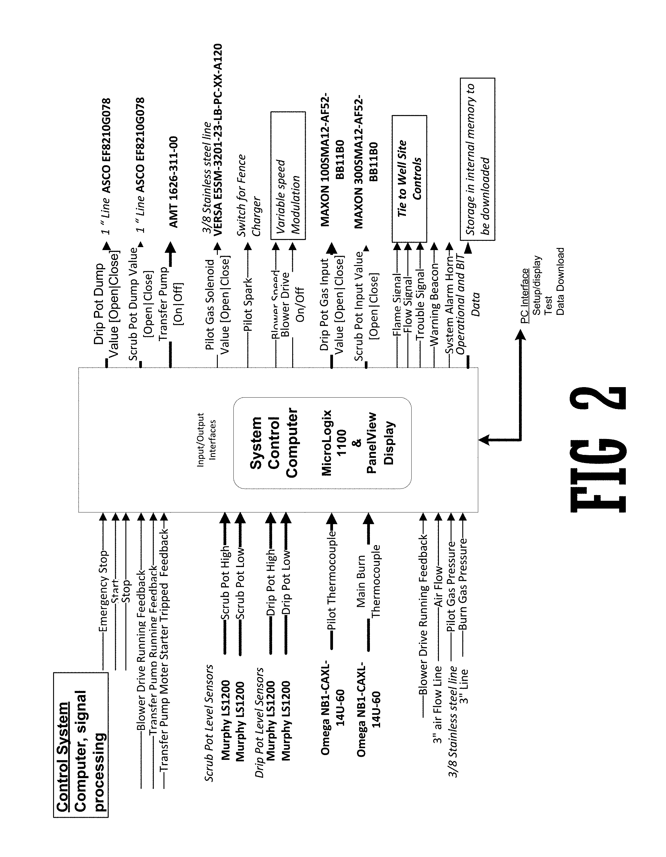
2. The portable flare described in claim 1 wherein the control system consists of relays, timers associated equipment to monitor key operating parameters to assure proper gas flow through the system thereby providing conditions for thermal destruction of the combustible pollutants.
Description
STATEMENT REGARDING FEDERALLY SPONSORED RESEARCH OR DEVELOPMENT
Not applicable
FIELD OF THE EMBODIMENTS
The field of the embodiments is oil field equipment, specifically oil field gas flares.
BACKGROUND OF THE EMBODIMENTS
The background of the embodiments involves the design of a portable flare.
SUMMARY OF THE EMBODIMENTS
This is a transportable forced air elevated Flare with a better than 98% burn efficiency. This is all built on a trailer to be able to move quickly to different locations. The unit is self-contained and can be quickly setup and put in operation without the use of cranes or other heavy equipment. The unit is also able to carry steel pipe and different types of hoses to allow this unit to tie to tank batteries or well heads.
BRIEF DESCRIPTION OF THE DRAWINGS
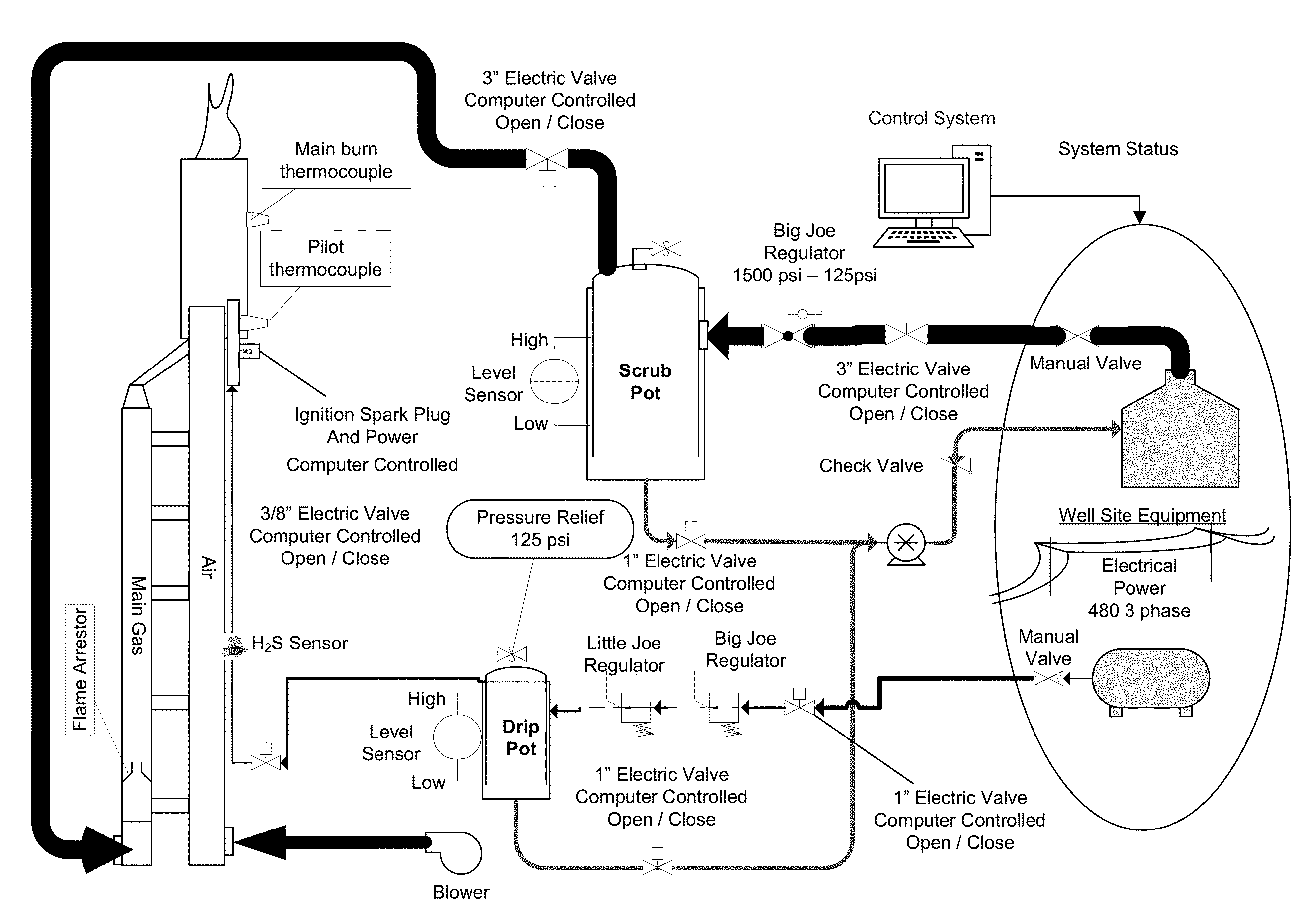
FIG. 1 is a schematic view of the Portable Flare.
FIG. 2 is a schematic view of the control system for the Portable Flare.
DETAILED DESCRIPTION OF THE PREFERRED EMBODIMENTS
A preferred embodiment of the Portable Flare 100 is comprised of a pilot light assembly, a transport assembly, an air tube, a gas tube, a blower, an air flow control means, a spark assembly, a flame tube, a control unit, and a hydraulic lift.
The pilot gas comes from the well site scrub pot or knockout tank thru a 1'' line. The flare pipe controls a valve to turn on and off the pilot gas to the flare. The pilot gas goes to a regulator taking pressure from 1500 psi down to 500 psi. This is then further reduced down to 125 psi with a second stage regulator. The pilot gas exits the drip pot through a 3/8'' stainless steel line via an electric solenoid for on and off control. A regulator in the 3/8'' line reduces the pressure down to ounces. The pilot gas then enters a 1/2'' pipe running up the side of the flare pipe to a burner. The pilot gas is ignited by a continuously sparking champion 200 spark plug. The pilot flame goes into an elbow which turns the flame across to the main outlet of gas and air to be burnt off.
The burn gas comes from the well site storage tanks thru a 2'' line connected to the flare pipe. The flare pipe controls a valve to turn on and off the burn gas to the flare. The first stage regulator will protect the flare pipe by reducing the burn gas pressure to 125 psi. This is to prevent a blowout from two much well head pressure. This pipe reduces down to a 2'' pipe which drops the burn gas into the 3'' air flow pipe and mixes the burn gas and air for a cleaner burn. Then this mixture of air and gas is ignited by the pilot flame then is burnt off inside the burn tube. The burn tube keeps the gas and air together for a clean burn. The burn tube is 6 ft. long and 8 inches in diameter and has air inlets to create a venturi effect to pull in additional assist air.
The air for the assist air flow is pulled from the environment and blown up the air tube. The clean burn is made possible with the injection of air to produce a hotter flame. The temperature of the flame is controlled by monitoring the flame temperature and adjusting the forced air flow with a blower fan forcing air up the air tube to mix with the burn gas. The hydraulic lift is comprised of a hydraulically actuated means to raise the air tube from the transportable position to the operating position.
The flare pipe control system consists of relays, timers associated equipment to monitor key operating parameters to assure proper gas flow through the system and the appropriate conditions for thermal destruction of the combustible pollutants. The key operating parameters to monitor are: a) Flame presence, based on temperature readings at the pilot and burn tube; and temperature at flare and combustion zone;
The trailer consists of a custom made DOT approve trailer with the flare system built on it.
* * * * *
D00000
D00001
D00002
XML
uspto.report is an independent third-party trademark research tool that is not affiliated, endorsed, or sponsored by the United States Patent and Trademark Office (USPTO) or any other governmental organization. The information provided by uspto.report is based on publicly available data at the time of writing and is intended for informational purposes only.
While we strive to provide accurate and up-to-date information, we do not guarantee the accuracy, completeness, reliability, or suitability of the information displayed on this site. The use of this site is at your own risk. Any reliance you place on such information is therefore strictly at your own risk.
All official trademark data, including owner information, should be verified by visiting the official USPTO website at www.uspto.gov. This site is not intended to replace professional legal advice and should not be used as a substitute for consulting with a legal professional who is knowledgeable about trademark law.