Methods and systems for network configuration
Zsigmond , et al.
U.S. patent number 10,225,097 [Application Number 15/982,687] was granted by the patent office on 2019-03-05 for methods and systems for network configuration. This patent grant is currently assigned to IKAN HOLDINGS LLC. The grantee listed for this patent is IKAN HOLDINGS LLC. Invention is credited to Sion Elie Douer, Frederico Wagner, Geraldo Yoshizawa, Fabio Zsigmond.


| United States Patent | 10,225,097 |
| Zsigmond , et al. | March 5, 2019 |
Methods and systems for network configuration
Abstract
Network and device configuration systems and methods are described. In an embodiment, a first user interface configured to receive from a user configuration information regarding a first network provided. Program code stored in computer accessible memory is configured to generate a barcode that includes information related to the first network configuration information, wherein the barcode can be scanned by a device having a barcode scanner and a network interface to configure the network interface to access the first network.
| Inventors: | Zsigmond; Fabio (Riverside, CT), Douer; Sion Elie (New York, NY), Yoshizawa; Geraldo (Sao Paulo, BR), Wagner; Frederico (New York, NY) | ||||||||||
|---|---|---|---|---|---|---|---|---|---|---|---|
| Applicant: |
|
||||||||||
| Assignee: | IKAN HOLDINGS LLC (New York,
NY) |
||||||||||
| Family ID: | 39827933 | ||||||||||
| Appl. No.: | 15/982,687 | ||||||||||
| Filed: | May 17, 2018 |
Prior Publication Data
| Document Identifier | Publication Date | |
|---|---|---|
| US 20180270077 A1 | Sep 20, 2018 | |
Related U.S. Patent Documents
| Application Number | Filing Date | Patent Number | Issue Date | ||
|---|---|---|---|---|---|
| 15397215 | Jan 3, 2017 | 9979558 | |||
| 14841960 | Jan 31, 2017 | 9559858 | |||
| 14505166 | Sep 22, 2015 | 9143401 | |||
| 13912555 | Oct 21, 2014 | 8864032 | |||
| 13303577 | Jun 18, 2013 | 8464953 | |||
| 12982445 | Nov 29, 2011 | 8066187 | |||
| 11934573 | Jan 4, 2011 | 7861933 | |||
| 60856993 | Nov 6, 2006 | ||||
| Current U.S. Class: | 1/1 |
| Current CPC Class: | H04L 67/04 (20130101); H04W 84/12 (20130101); H04L 63/083 (20130101); H04W 76/11 (20180201); H04L 12/2807 (20130101); H04L 41/0889 (20130101); G06K 19/06028 (20130101); H04L 41/0806 (20130101); H04L 41/0886 (20130101); H04L 67/34 (20130101); H04W 88/02 (20130101) |
| Current International Class: | G06K 7/10 (20060101); G06K 17/00 (20060101); H04L 29/08 (20060101); H04L 12/28 (20060101); G06K 19/00 (20060101); H04W 76/11 (20180101); H04W 88/02 (20090101); G06K 19/06 (20060101); H04W 84/12 (20090101); H04L 12/24 (20060101); H04L 29/06 (20060101) |
| Field of Search: | ;235/375,462.01,462.15,462.45,472.01-472.03 |
References Cited [Referenced By]
U.S. Patent Documents
| 4825058 | April 1989 | Poland |
| 4916441 | April 1990 | Gombrich |
| 5250789 | October 1993 | Johnsen |
| 5424524 | June 1995 | Ruppert et al. |
| 5465291 | November 1995 | Barrus et al. |
| 5488223 | January 1996 | Austin et al. |
| 5640002 | June 1997 | Ruppert et al. |
| 5664110 | September 1997 | Green et al. |
| 5748899 | May 1998 | Aldrich |
| 5777315 | July 1998 | Wilz et al. |
| 5837986 | November 1998 | Barile et al. |
| 5869840 | February 1999 | Helton |
| 5923735 | July 1999 | Swartz et al. |
| 5962839 | October 1999 | Eskildsen |
| 5971277 | October 1999 | Cragun et al. |
| 5979762 | November 1999 | Bianco |
| 5992752 | November 1999 | Wilz et al. |
| 6076068 | June 2000 | OeLapa et al. |
| 6149063 | November 2000 | Reynolds |
| 6321989 | November 2001 | Wilz et al. |
| 6347743 | February 2002 | Wilz et al. |
| 6434530 | August 2002 | Sloane et al. |
| 6435407 | August 2002 | Fiordelisi |
| 6459863 | October 2002 | Kawabe |
| 6565005 | May 2003 | Wilz et al. |
| 6609197 | August 2003 | Ketcham |
| 6622919 | September 2003 | Wilz et al. |
| 6640214 | October 2003 | Nambudiri et al. |
| 6688522 | February 2004 | Philyaw et al. |
| 6802659 | October 2004 | Cremon et al. |
| 6807263 | October 2004 | Kible et al. |
| 6857013 | February 2005 | Ramberg et al. |
| 6873435 | March 2005 | Tehranchi et al. |
| 7028902 | April 2006 | Xu et al. |
| 7080777 | July 2006 | Wagner et al. |
| 7086592 | August 2006 | Wagner et al. |
| 7165721 | January 2007 | Wagner et al. |
| 7281655 | October 2007 | Wagner et al. |
| 7303124 | December 2007 | Wagner et al. |
| 7306153 | December 2007 | Chong et al. |
| 7328842 | February 2008 | Wagner et al. |
| 7344063 | March 2008 | Wagner et al. |
| 7410099 | August 2008 | Fukasawa et al. |
| 7505928 | March 2009 | Lebaschi |
| 7558838 | July 2009 | Philyaw |
| 7681792 | March 2010 | Wagner et al. |
| 7861933 | January 2011 | Zsigmond |
| 7946493 | May 2011 | Havens et al. |
| 8041951 | October 2011 | Want et al. |
| 2001/0046862 | November 2001 | Coppinger |
| 2002/0008145 | January 2002 | Walsh et al. |
| 2002/0143550 | October 2002 | Nakatsuyama |
| 2002/0161658 | October 2002 | Sussman |
| 2002/0185540 | December 2002 | Hashimoto et al. |
| 2003/0030841 | February 2003 | Parry |
| 2003/0034391 | February 2003 | Wagner et al. |
| 2003/0114176 | June 2003 | Phillips |
| 2004/0065739 | April 2004 | Xu et al. |
| 2004/0199545 | October 2004 | Wagner et al. |
| 2004/0206821 | October 2004 | Longacre |
| 2005/0011958 | January 2005 | Fukasawa et al. |
| 2005/0086328 | April 2005 | Landram et al. |
| 2005/0182652 | August 2005 | McIntyre et al. |
| 2005/0260973 | November 2005 | van de Groenendaal |
| 2006/0000910 | January 2006 | Chong et al. |
| 2006/0106623 | May 2006 | Lebaschi |
| 2006/0221915 | October 2006 | Gatta |
| 2007/0008925 | January 2007 | Dravida et al. |
| 2007/0010248 | January 2007 | Dravida et al. |
| 2007/0027964 | February 2007 | Herrod |
| 2008/0056722 | March 2008 | Hendrix |
| 2008/0086414 | April 2008 | Ching |
| 2008/0133264 | June 2008 | Wagner et al. |
| 2009/0147700 | June 2009 | Sewall |
| 2010/0048242 | February 2010 | Rhoads et al. |
| 2013/0107748 | May 2013 | Dravida et al. |
| 2013/0185403 | July 2013 | Vachharajani et al. |
| 2013/0206832 | August 2013 | Hashimoto |
| 2014/0050319 | February 2014 | Pang et al. |
| 2014/0071942 | March 2014 | Ye |
| 2014/0214628 | July 2014 | Argue et al. |
| 2015/0379607 | December 2015 | Pedley et al. |
| 2016/0267565 | September 2016 | Katcher |
| 2017/0293965 | October 2017 | Sasaki et al. |
| 2018/0005631 | January 2018 | Lee et al. |
| 100 17 503 | Oct 2001 | DE | |||
Other References
|
Supplementary European Search Report; Application No. 04713957.1; dated Sep. 3, 2008. cited by applicant. |
Primary Examiner: Vo; Tuyen K
Attorney, Agent or Firm: Knobbe, Martens, Olson & Bear LLP
Claims
What is claimed is:
1. A configurable computing system, comprising: a computer device; a network antenna; an IEEE 802.11 network interface; a camera; and non-transitory computer readable memory having program instructions stored thereon that when executed by the computing device cause the system to at least: read a barcode using the camera, the barcode comprising an encoded IEEE 802.11 network password; cause the read barcode to be translated to obtain data comprising the IEEE 802.11 network password; use the obtained IEEE 802.11 network password to enable the configurable computing system to access a local IEEE 802.11 wireless network using the IEEE 802.11 network interface without a user having to manually key in an IEEE 802.11 network password for the local IEEE 802.11 wireless network on the configurable computing system.
2. The configurable computing system as defined in claim 1, further comprising a touch screen, a personal digital assistant, a video capture device, and a light source, wherein the instructions, when executed by the computing device, are configured to enable the user to generate a list using voice, and to translate the barcode to obtain a network identifier, and utilize the obtained IEEE 802.11 network identifier in enabling access to the local IEEE 802.11 network.
3. The configurable computing system as defined in claim 1, wherein the instructions, when executed by the computing device, are configured to translate the barcode to obtain a network identifier, and utilize the obtained IEEE 802.11 network identifier in enabling access to the local IEEE 802.11 network.
4. The configurable computing system as defined in claim 1, wherein the configurable computing system has a display less than ten inches diagonal and has fewer than ten physical keys.
5. The configurable computing system as defined in claim 1, wherein the configurable computing system comprises an oven, refrigerator, blender, television, a video game system, or a waste receptacle.
6. The configurable computing system as defined in claim 1, wherein the configurable computing system camera is configured to read a barcode displayed by an electronic device.
7. The configurable computing system as defined in claim 1, wherein the configurable computing system camera is configured to read a barcode printed by a printer.
8. The configurable computing system as defined in claim 1, wherein the configurable computing system is configured to access operational information, in addition to an IEEE 802.11 network password, using the read barcode.
9. The configurable computing system as defined in claim 1, wherein the camera comprises a lens and is configured to translate optical impulses into electrical signals.
10. The configurable computing system as defined in claim 1, wherein the configurable computing system comprises at least one user configurable button and a touch screen.
11. The configurable computing system as defined in claim 1, wherein the barcode comprises a quiet zone and a check character, wherein the check character is a calculated value based on other characters encoded in the barcode.
12. The configurable computing system as defined in claim 1, wherein the configurable computing system comprises a light source.
13. The configurable computing system as defined in claim 1, wherein the configurable computing system comprises a personal digital assistant.
14. The configurable computing system as defined in claim 1, wherein the configurable computing system is configured to enable the user to generate a list using voice.
15. A computer-implemented method, the method comprising: reading using a camera, by a configurable computing system, a barcode or other computer readable visual indicia, the configurable computing system comprising computer hardware including the camera, a processor and an IEEE 802.11 network interface, the configurable computing system configured with specific executable instructions; utilizing, by the configurable computing system, the read barcode or other computer readable visual indicia to obtain an IEEE 802.11 wireless network password of an IEEE 802.11 network; and using, by the configurable computing system, the IEEE 802.11 wireless network password to access a local IEEE 802.11 wireless network without a user having to manually key in the IEEE 802.11 wireless network password on the configurable computing system, wherein the IEEE 802.11 wireless network password is used to enable the configurable computing system to communicate over the local IEEE 802.11 wireless network via the IEEE 802.11 network interface.
16. The computer-implemented method as defined in claim 15, the method further comprising: utilizing, by the configurable computing system, the read barcode or other computer readable visual indicia to obtain a network identifier, wherein using, by the configurable computing system, the IEEE 802.11 wireless network password to access the local IEEE 802.11 wireless network further comprises using the network identifier to access the local IEEE 802.11 network.
17. The computer-implemented method as defined in claim 15, wherein reading, using the camera, the barcode or other computer readable visual indicia further comprises reading the barcode or other computer readable visual indicia from a display of an electronic device.
18. The computer-implemented method as defined in claim 15, wherein reading, by the configurable computing system, the barcode or other computer readable visual indicia further comprises reading, by the configurable computing system, a barcode printed by a printer.
19. The computer-implemented method as defined in claim 15, wherein the barcode or other computer readable visual indicia comprises a barcode having a quiet zone and a check character, wherein the check character is a calculated value based on other characters encoded in the barcode.
20. The computer-implemented method as defined in claim 15, wherein the configurable computing system comprises a home appliance.
21. The computer-implemented method as defined in claim 15, wherein reading a barcode or other computer readable visual indicia comprises reading a barcode.
22. The computer-implemented method as defined in claim 15, wherein the configurable computing system comprises a touch screen, a light source, and an antenna.
23. The computer-implemented method as defined in claim 15, the method further comprising enabling the user to record a voice memo using the configurable computing system.
24. The computer-implemented method as defined in claim 15, the method further comprising enabling the user to generate a shopping list using a voice input via the configurable computing system.
25. A non-transitory storage medium, said non-transitory storage medium having stored thereon executable program instructions that when executed by a computer system are configured to cause the computer system to perform operations comprising: read a barcode or other computer readable visual indicia; cause translation of the read barcode or other computer readable visual indicia to obtain a password of an IEEE 802.11 network; utilize the IEEE 802.11 network password obtained by translation of the read barcode or other computer readable visual indicia to enable the computer system to access the IEEE 802.11 wireless network using an IEEE 802.11 network interface of the computer system without a user having to manually key in the IEEE 802.11 network password on the computer system; and enable the computer system to communicate over the IEEE 802.11 wireless network.
26. The non-transitory storage medium as defined in claim 25, wherein: the computer readable visual indicia is not a barcode, and wherein reading the computer readable visual indicia further comprises reading computer readable visual indicia from an electronic device display.
27. The non-transitory storage medium as defined in claim 25, wherein: the computer readable visual indicia is a barcode.
28. The non-transitory storage medium as defined in claim 25, wherein the computer system comprises a home appliance.
29. The non-transitory storage medium as defined in claim 25, wherein the executable program instructions direct the computer system to enable the user to record a voice memo using the configurable computing system.
30. The non-transitory storage medium as defined in claim 25, wherein the executable program instructions direct the computer system to enable the user to generate a list using a voice input.
Description
INCORPORATION BY REFERENCE TO ANY PRIORITY APPLICATIONS
Any and all applications for which a foreign or domestic priority claim is identified in the Application Data Sheet as filed with the present application are hereby incorporated by reference under 37 CFR 1.57.
STATEMENT REGARDING FEDERALLY SPONSORED R&D
Not applicable.
PARTIES OF JOINT RESEARCH AGREEMENT
Not applicable.
REFERENCE TO SEQUENCE LISTING, TABLE, OR COMPUTER PROGRAM LISTING
Not applicable.
BACKGROUND OF THE INVENTION
Field of the Invention
The present invention is related to electronic devices, and in particular, to methods and systems for configuring electronic devices.
Description of the Related Art
With the rapid increase in networkable consumer electronic systems, such as Internet radios, televisions with computer interfaces, and the like, there has been a rapid increase in consumer frustration regarding the configuration of such electronic systems so as to be able to access a network, such as the Internet.
For example, a conventional network configuration process (wherein the target network is the Internet), may involve accessing a network configuration user interface, entering the name of an Internet Service provider, specifying a network connection-type, specifying whether the connection is to be made via a broadband connection that needs a user name and password, via an "always-on" broadband connection that does not require a sign-in, or via a connection is to be made using a dial-up modem, specifying security related information, etc. Such a conventional process is difficult to perform on electronic devices having small screens not capable of displaying extensive user interfaces and/or having limited keyboards (e.g., that do not have an alphanumeric keyboard).
SUMMARY OF THE INVENTION
Example embodiments are described that enable configuration of device settings, such as a network interface, using a printed visual code read or accessed by the device.
An example embodiment provides a network configuration system, comprising a first user interface configured to receive from a user configuration information regarding a first network. The system further includes program code stored in computer readable memory configured to generate a barcode that includes information related to the first network configuration, where the barcode can be scanned by a device that has a barcode scanner that converts the barcode into digital data and the device uses at least a portion of the data to configure a network interface to access the first network.
An example embodiment provides a configuration system, comprising: a first user interface configured to receive from a user configuration information regarding a first device associated with the user; and program code stored in computer accessible memory configured to generate a visual code that includes information related to the first device configuration information, wherein the visual code can be read by the first device to configure, at least in part, the first device.
An example embodiment provides a method of providing network configuration information, comprising: causing at least in part a first user interface to be displayed to a user on a user terminal, the first user interface including fields for receiving configuration information for a first electronic device network interface; causing at least in part information provided by the user via the first user interface to be encoded in computer readable optical code, wherein the optical code can be read by the first electronic device using an optical image capture device; and causing at least in part the optical code to be displayed and/or printed via the user terminal, wherein the optical code is configured to be scanned to obtain the network interface configuration information.
An example embodiment provides a configurable system, comprising: a processor; memory coupled to the processor; a computer program stored in the memory that is executable by the processor; a network interface; and an optical reader, wherein the computer program is configured to utilize information read by the optical reader to configure network settings.
An example embodiment provides a method of configuring a system, comprising: causing, at least in part, an optical code to be read by the system using an optical reader that converts image information to digital data; and causing, at least in part, the digital data to be used to configure the operation of at least a network connection.
An example embodiment provides a method of configuring an electronic device, comprising: using an optical reader to read a visual code to obtain data encoded therein; and configuring a network connection of the electronic device using at least a portion of the data.
BRIEF DESCRIPTION OF THE DRAWINGS
Embodiments of the present invention will now be described with reference to the drawings summarized below. These drawings and the associated description are provided to illustrate example embodiments of the invention, and not to limit the scope of the invention.
FIG. 1 illustrates an example configuration flow chart.
FIGS. 2A-C illustrate example user interfaces for receiving device settings.
FIGS. 3A-C illustrate example user interfaces displayed by a device being configured.
FIG. 3D illustrates an example optical code format.
FIG. 4 illustrates an example networked system,
FIG. 5 illustrates an example configurable electronic system.
DETAILED DESCRIPTION OF PREFERRED EMBODIMENTS
Example systems and methods are described herein for configuring network settings on a device based on the characteristics of an available network and/or for setting user preferences for the device. Certain embodiments utilize visual indicia read by an optical reader to perform network configuration and/or to set user preferences for an electronic device.
As discussed above, certain conventional approaches for configuring an electronic device to access a network are overly complex for a typical consumer. Further, many conventional approaches rely on the device having a relatively large and expensive screen for displaying complex and detailed user interface, and having a relatively large keyboard (e.g., an alphanumeric keyboard) for entering in network configuration data. It would be advantageous to make it easier for a consumer to configure a consumer electronic device and to reduce the hardware requirements of the electronic device.
As discussed below, certain embodiments encode network configuration information and/or user preferences for an electronic device in an optical/visual code (e.g., a barcode) and utilize an optical reader, such as a barcode scanner, coupled to the electronic device to read the optical code. The electronic device then performs the network configuration and/or configures other device settings in accordance with the user preferences.
Throughout the following description, the term "Web site" is used to refer to a user-accessible network site that implements the basic World Wide Web standards for the coding and transmission of hypertextual documents. These standards currently include HTML (the Hypertext Markup Language), HTTP (the Hypertext Transfer Protocol), Java, and XML. It should be understood that the term "site" is not intended to imply a single geographic location, as a Web or other network site can, for example, comprise multiple geographically distributed computer systems that are appropriately linked together.
Furthermore, while the following description relates to an embodiment utilizing the Internet and related protocols, other networks and other protocols may be used as well. In addition, unless otherwise indicated, the functions described herein may be performed by executable code and instructions running on one or more general-purpose computers. For example, program code stored in non-volatile and/or volatile memory can include one or more instructions, which can optionally be straight-line code and/or organized as modules or objects configured to receive and process inputs, provide outputs, and to selectively store data. However, the present invention can also be implemented using special purpose computers, state machines, and/or hardwired electronic circuits. While certain example processes are described herein, not all the process states need to be performed, and the order of the process can be varied.
While certain example embodiments are described with reference to barcodes (e.g., linear barcodes, stacked barcodes, matrix barcodes, etc.) and barcode scanners, other computer readable indicia (e.g., dots, concentric circles, text codes hidden within images, text readable using optical character recognition systems, etc.) and scanners/image capture devices can be used. For example, a scanner/image capture device can be a laser scanner (e.g., including light source, a lens and a photo conductor translating optical impulses into electrical ones), a still frame camera, a video capture device, etc. While certain types of networks may be referred to (e.g., an IEEE 802.11 wireless network) other networks may be utilized (e.g., cellular networks, IEEE 802.16 networks, etc.). While the illustrated user interfaces may user certain language and provide certain user instructions, other language and instructions may be used.
In an example embodiment, a networked user terminal (e.g., a personal computer, an interactive television, a smart phone, a personal digital assistant, a networked-enabled digital music/video player, etc.) scans for existing wireless networks (or otherwise accesses information regarding local networks) and displays (e.g., via a computer system display) a listing of available networks (e.g., one or more IEEE 802.11 wireless networks) to the user. By way of example, a WiFi scanner can be used to discover wireless nodes (e.g., access point and wireless clients). The user chooses (e.g., by clicking on a network entry in the network listing) which network the user wants to configure a second device to access. By way of example, the second device has a barcode or other optical scanner. By way of further example, the second device can be a processor-based terminal, including a display, a keyboard, memory, a wired and/or wireless network interface, and a scanner/camera.
Optionally, the second device can be configured to be used to scan product information, such as that encoded in barcodes on household or business consumable items, such as food packaging. By way of further example, the second device can be a kitchen appliance (e.g., an oven, refrigerator, blender, television, computer, a waste receptacle, etc.) including or coupled to an optical scanner and including a network interface.
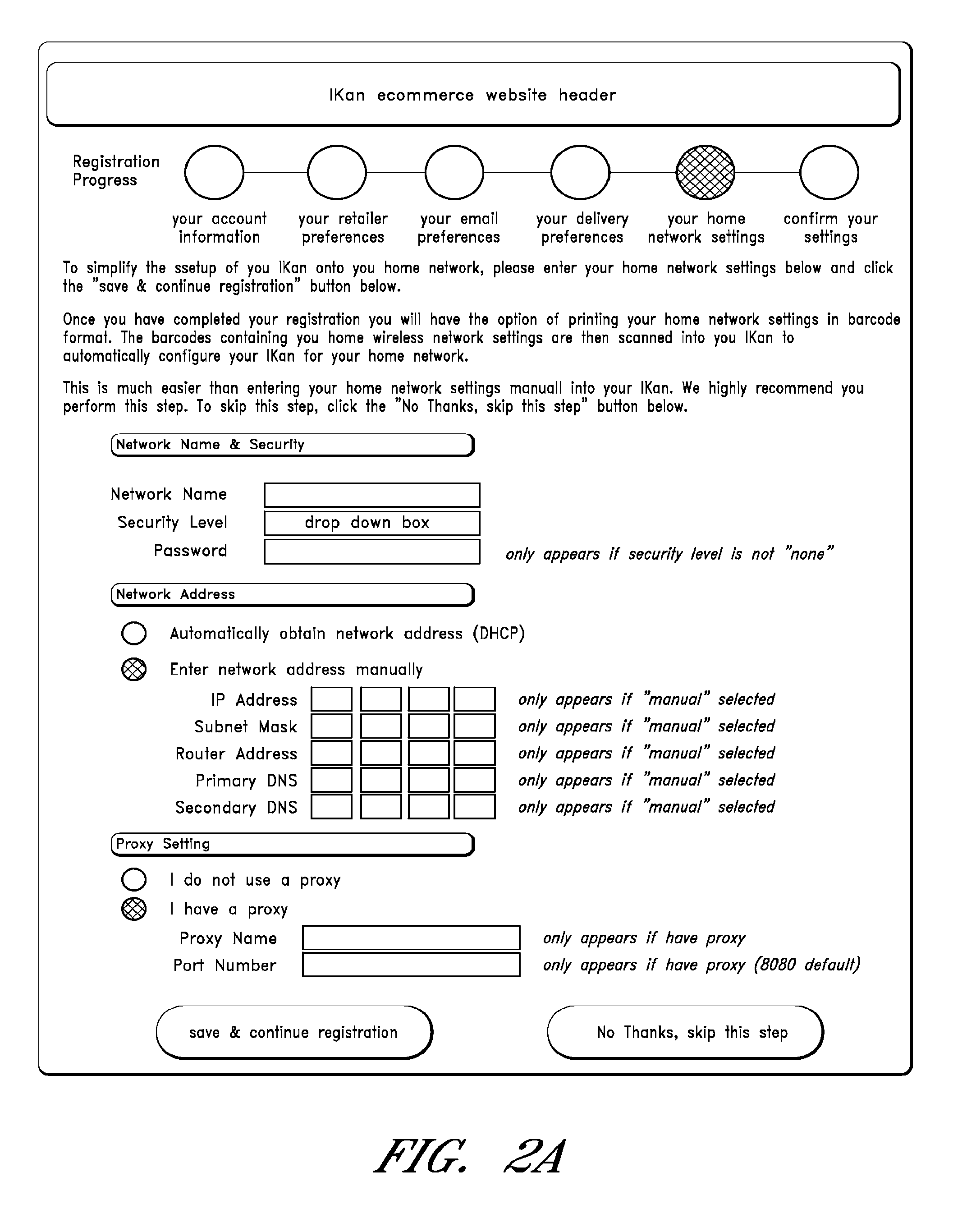
A user interface is provided that enables a user to input/select certain network information (e.g., what network the second device is to use, what is the security method being used, such as WEP, a network password, a network address, a proxy setting, etc.). Some or all of the information may be prepopulated based on information stored on or accessed by the computer system. The user interface may be provided by an application stored on the user's computer system or may be accessed over a network from a remote server (e.g., over the Internet, wherein the user interface is provided as a Web page or pages by a Web page server).
Additionally, a user interface is optionally provided via which a user can input device preferences, such as energy management settings (e.g., when or after what period of non-use the second device is to power down or enter a lower power consumption mode, such as by turning off the second device display until the user presses a button or otherwise uses the second device), display brightness, display contrast, and/or other preferences. The input/selected information can be stored locally in memory on the user computer system and/or remotely or a remote computer system (e.g., the computer system that provided the user interface).
Based on the selected/input information (e.g., configuration settings and/or preferences), the barcode generation application generates barcodes or other computer readable indicia/codes which can be printed (e.g., by a printer connected to the user computer system) in response to a user instruction or otherwise. The printed barcode(s) are then placed beneath or otherwise positioned with respect to the second device scanner, which then scans the code. The second device then configures its network setting and/or preference settings in accordance with the scanned code.
FIG. 1 illustrates an example configuration process for a target electronic device, (e.g., the scanning system described in U.S. Pat. No. 7,165,721, incorporated herein by reference, or other electronic device). The target device optionally has a relatively small display (e.g., less than 10 inches diagonal), and may have a relatively small keyboard (e.g., 9 keys or less, 5 keys or less, etc.). Optionally instead, the target device has a relatively large display and a relatively large keyboard. At state 102, a user accesses a website hosted by a remote system (e.g., an electronic commerce system, such as one that tracks user consumption of items and processes item orders received over a network or otherwise) via a terminal (e.g., a personal computer) coupled to a Website. The terminal may be equipped with a relatively large display (e.g., 10 inches or more diagonally) and may be further equipped with an alphanumeric keyboard.
The user then proceeds to register to create an account (or if the user already has an account, the user can log in to edit/modify account information). For example, the user may be asked to provide a user name, contact information (e.g., email, physical address, phone number, etc.), identification information regarding the device to be configured (e.g., a part number and/or a serial number), payment information (e.g., a credit card number, a debit card number, etc.), and/or other information. In addition, the user may be asked to provide user preference information.
For example, if the target electronic device is intended to collect information regarding items consumed by the user and to generate shopping lists for replacement items, the user may be asked to specify user preferences related to how often to reorder items, who orders are to be placed with (e.g., which retailer/supermarket), how items are to be delivered, when items are to be delivered, what types of status notifications are to be automatically provided to the user, etc. Other example user preferences are described in U.S. Pat. No. 7,165,721.
Optionally, a user interface is provided via which the user can specify device settings. For example, the user can specify when (e.g., how long after the last use of the device) the device should enter a low power consumption mode (e.g., turn off display backlighting, let device hard drive spin down, turn off network radio, etc.). The information provided by the user at state 102 is stored in a user database or other data store.
In addition, a user is requested to provide/select network settings via a network configuration user interface. For example, the user may be asked to provide (by typing in, selecting from a menu, or otherwise) some or all of the following and/or other information:
Network name;
Network security level;
Password (if the security level necessitates a password);
Network address (e.g., IP address, subnet mask, router, DNS primary, DNS secondary, or an indication that the system is to automatically obtain the network address);
Proxy name and port number (if a proxy is being used).
When the user has provided the network configuration data, the user can select a "save" control and the data is stored locally on the user terminal and/or in the user database.
At state 104, the remote system (or the terminal) encodes the network configuration information using a barcode generator and preferences related to the electronic device into an optical code (e.g., a barcode). For example, the network name, security level, password, IP address, subnet mask, router, DNS, Proxy name, proxy port number can be encoded into a barcode, as illustrated in FIG. 3D.
Optionally, the system can encode other types of information into the barcode and/or additional barcodes. For example, the system can encode a Uniform Resource Locator (URL) or other locator which the device is to access and obtain information or programs. For example, the URL can access a Web site via which a new version of an operating system or program for the device can be downloaded to and installed by the device. By way of further example, the URL can access a site via which an item catalog or catalog data (or other database) can be downloaded.
At state 106, the remote system transmits the optical code in digital form (e.g., as a digital image or as data that can be converted by the terminal into an image) over the network to the user terminal. At state 108, the user prints out the optical code using a printer (e.g., a laser printer, an ink jet printer, a thermal printer, a sublimation printer, etc.) coupled to the user terminal (optionally, the user can scan the code directly from the terminal display without printing out the optical code).
At state 110, the user scans the optical code (e.g., from the printed hardcopy version or from the terminal display) using an optical scanner coupled to the electronic device. The scanner translates the optical code to digital data which is then stored in device memory. The digital data is provided/accessed by a corresponding program hosted on the device. The corresponding program then utilizes the digital data appropriately. For example, at state 112, a network configuration program accesses the network configuration portion of the data and configures the network interface accordingly. At state 114, the device connects to a network. At state 116, the device communicates with the system.
Certain example user interfaces with now be described with reference to FIGS. 2AC. FIG. 2A illustrates an example user interface that can be utilized by a user to provide network configuration information to the system. The user interface display instructions for the user regarding providing network settings via the user interface. Corresponding fields are provided to receive the network settings. In this example, the following fields are provided (although other fields can be provided as well):
Network name;
Security level;
Password;
Automatically obtain network address check box (to instruct the device to automatically obtain the network address using, in this example, Dynamic Host Configuration Protocol);
Manually enter network address checkbox (to enable the user to enter network address information);
Fields for receiving manually entered network address information (IP address field, Subnet Mask field, Router address, Primary DNS, Secondary DNS);
Proxy name field;
Proxy port address.
A control is provided via which the user can instruct the system to save the network configuration system information;
A control is provided via which the user can skip entering data via the illustrated user interface (e.g., when the user would rather perform network configuration directly on the target device).
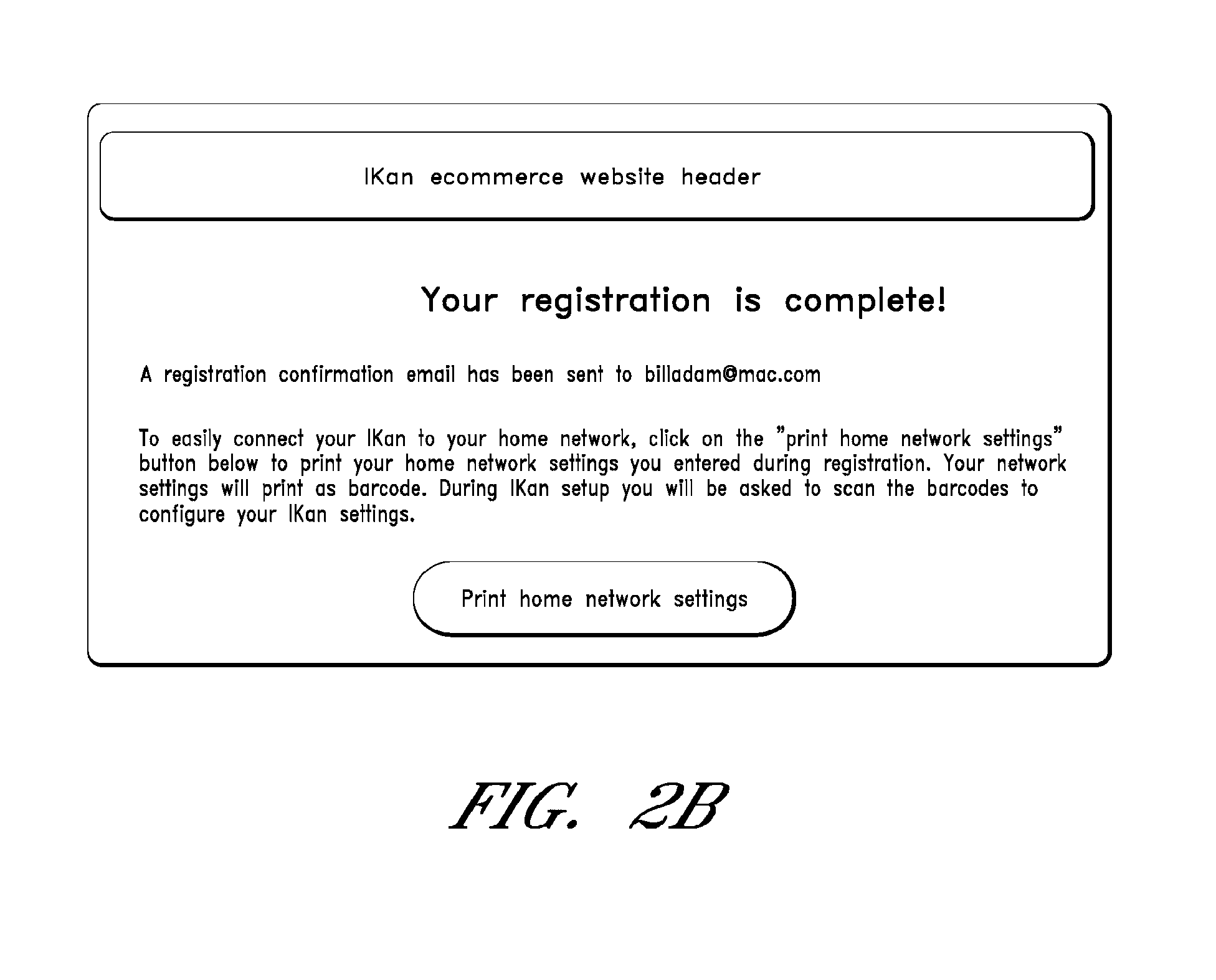
FIG. 2B illustrates a user interface presented once the user has completed the registration process. The user interface further instructs the user to print out the barcodes corresponding to the network settings and to scan the barcodes via the target device.
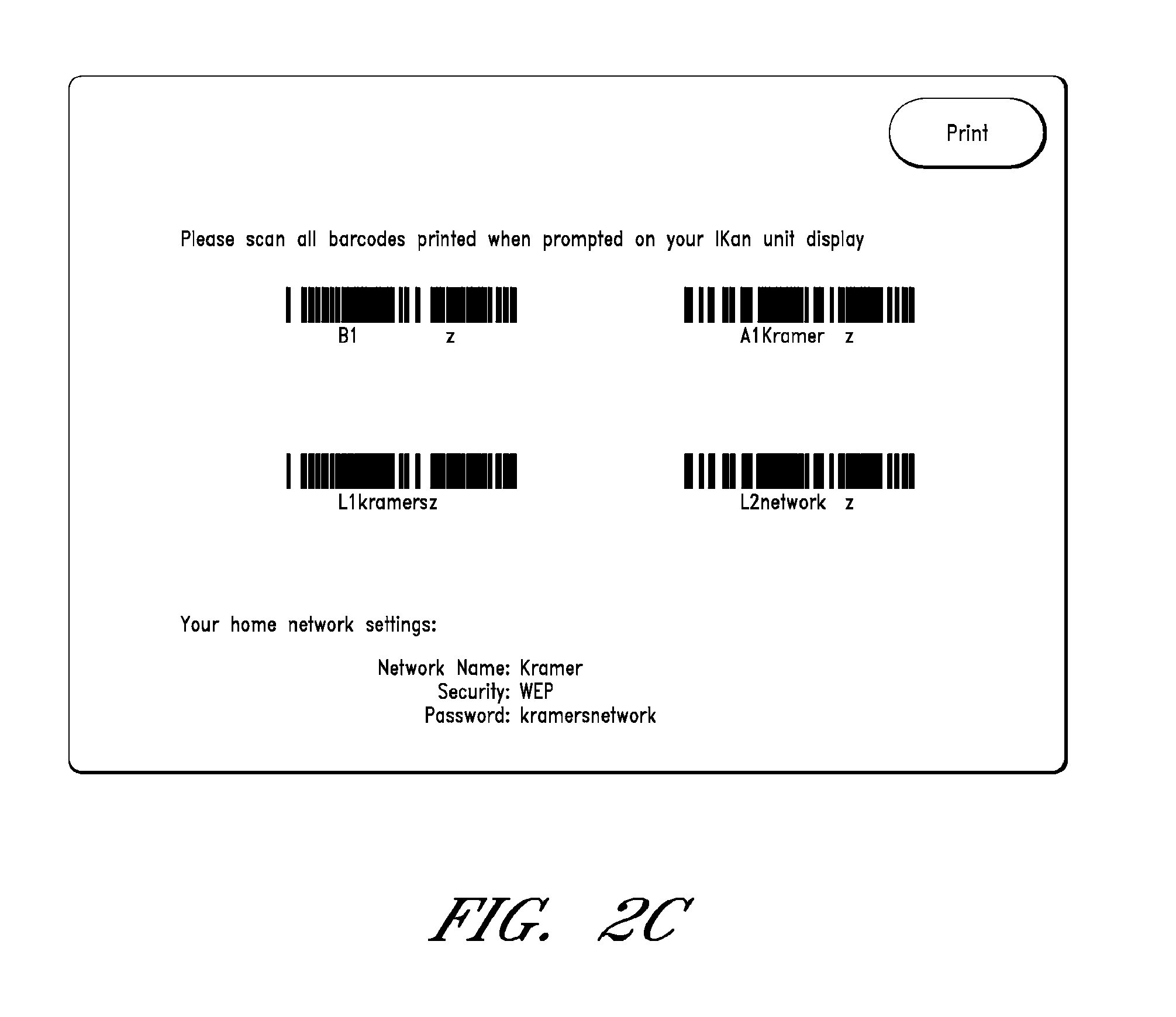
FIG. 2C illustrates an example print out of the barcodes corresponding to the network configuration data. In addition to barcode data, human readable text is provided including, in this example, the network name, security level, and password specified by the user. Other user provided data can be textually provided as well. Instructions on the use of he barcode are also provided.
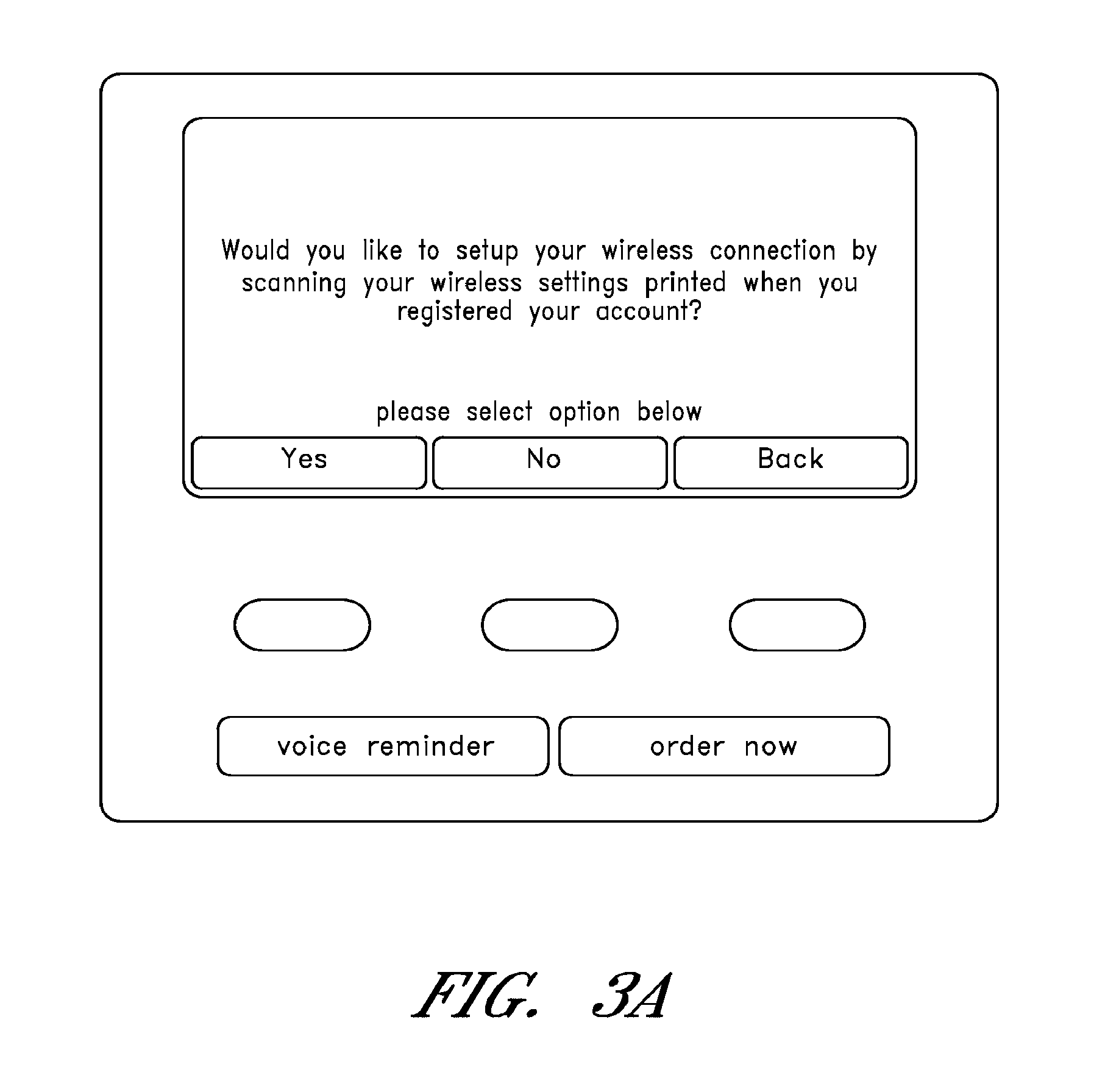
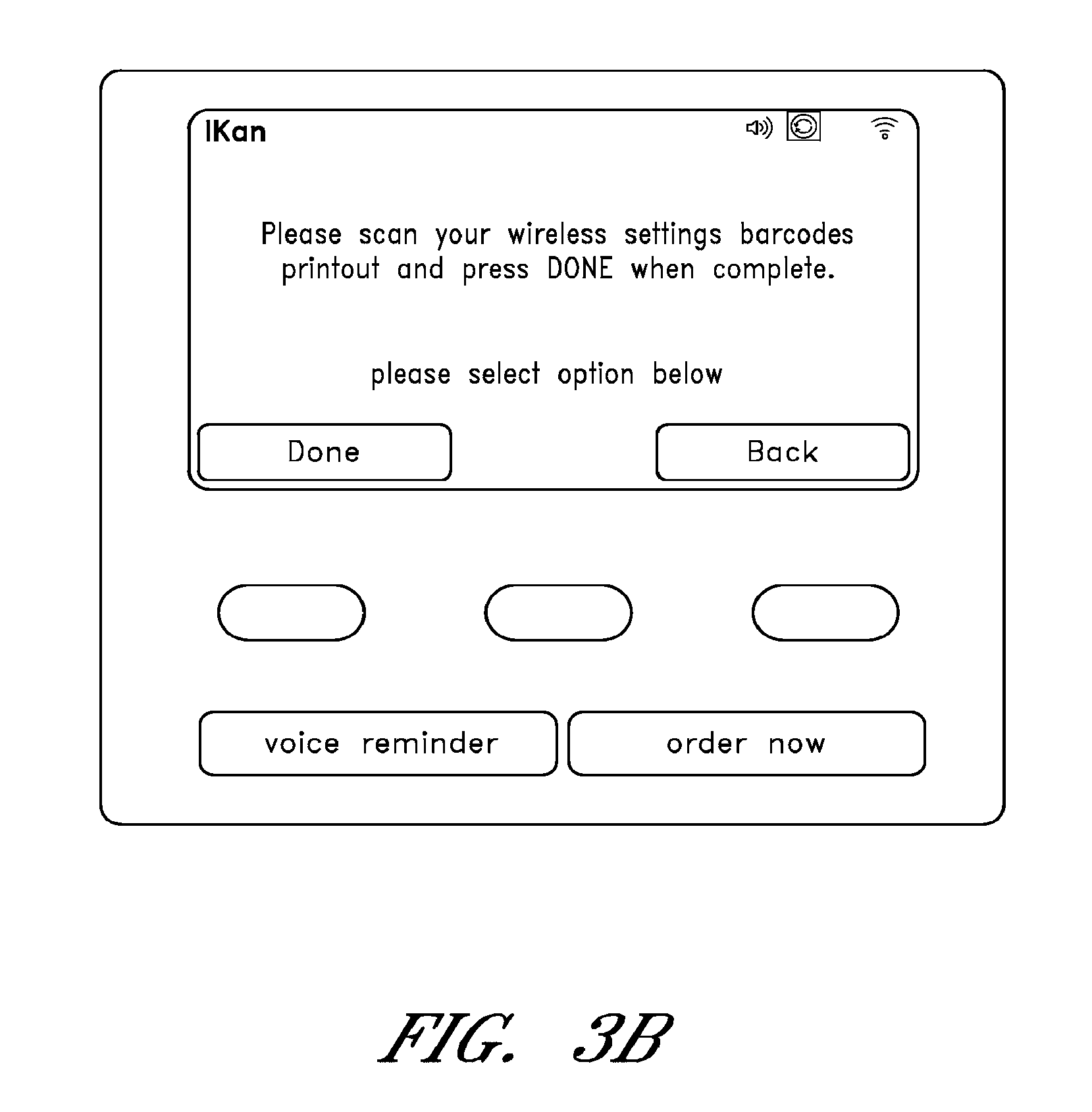
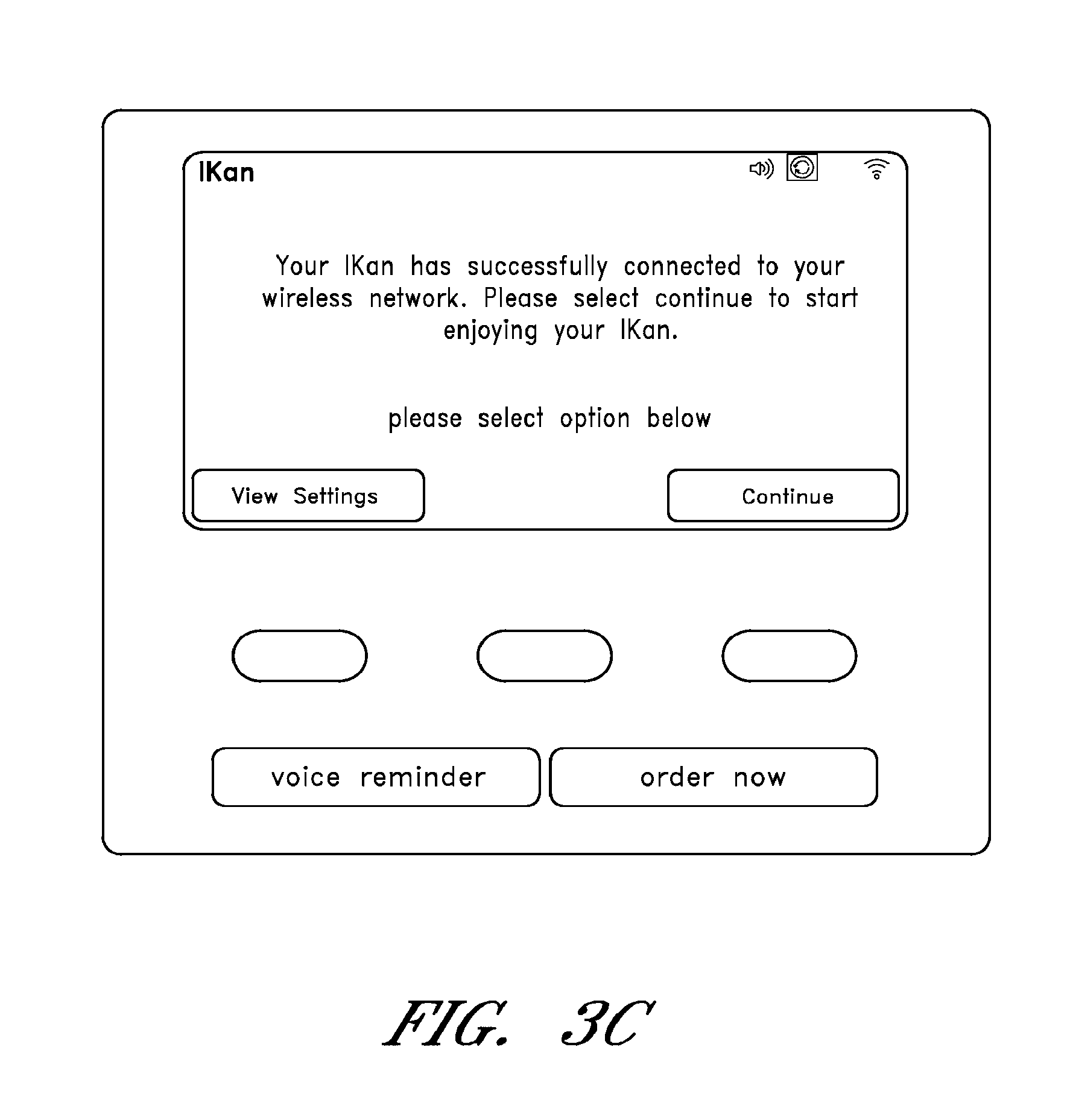
FIGS. 3A-C illustrate example user interfaces for adding the target device to the user's network that are presented on an example target device display. In this example, the device includes three buttons whose functions may change and whose current functions are described by text/labels presented via the device display. In addition two buttons of fixed function with fixed labels are provided (a voice reminder/memo button to initiate recording of a voice memo/shopping list, and "order now" button to cause a substantially immediate order to be placed for a pending shopping list).
Referring to FIG. 3A, the example user interface asks the user if the user would like to setup a wireless network connection by having the device scan the printed wireless settings. The programmable buttons function respectively as a "yes" input, a "no" input, and a "back" button (to return to a previous menu). If the user activates the "yes" button, the example menu illustrated in FIG. 3B is presented. The user interface instructs the user to scan the wireless network setting barcodes printout and to press the "done" control when complete. One of the buttons is labeled "done" and another button is labeled "back".
If the user activates the "done" button, once the device configures the network interface and successfully connects to a local network in accordance with the settings specified in the barcode, the example user interface displayed in FIG. 3C is presented on the device. The illustrated user interface informs the user that the device has successfully connected to the user's network and instructs the user to activate a control to begin using the networked device.
FIG. 3D illustrates an example barcode in code 128 barcode format and the relative position of the network setting information and of a calculated check digit. Code 128 is a linear symbology that encodes numbers, text functions and the 128 ASCII character set (from ASCII 0 to ASCII 128). A Code 128 barcode includes the following sections:
Quiet Zone;
Start Character;
Encoded Data;
Check Character;
Stop Character;
Quiet Zone.
The check character is calculated from a modulo 103 calculation of the weighted sum of all the characters.
Of course other barcode types can be used, including, without limitation: UPC, Code 25, Code 39, Code 93, Code 11, ITF-14, Codablock, Code 16K, PDF417, Aztec Code, bCode, Code 16K, PDF417, etc.
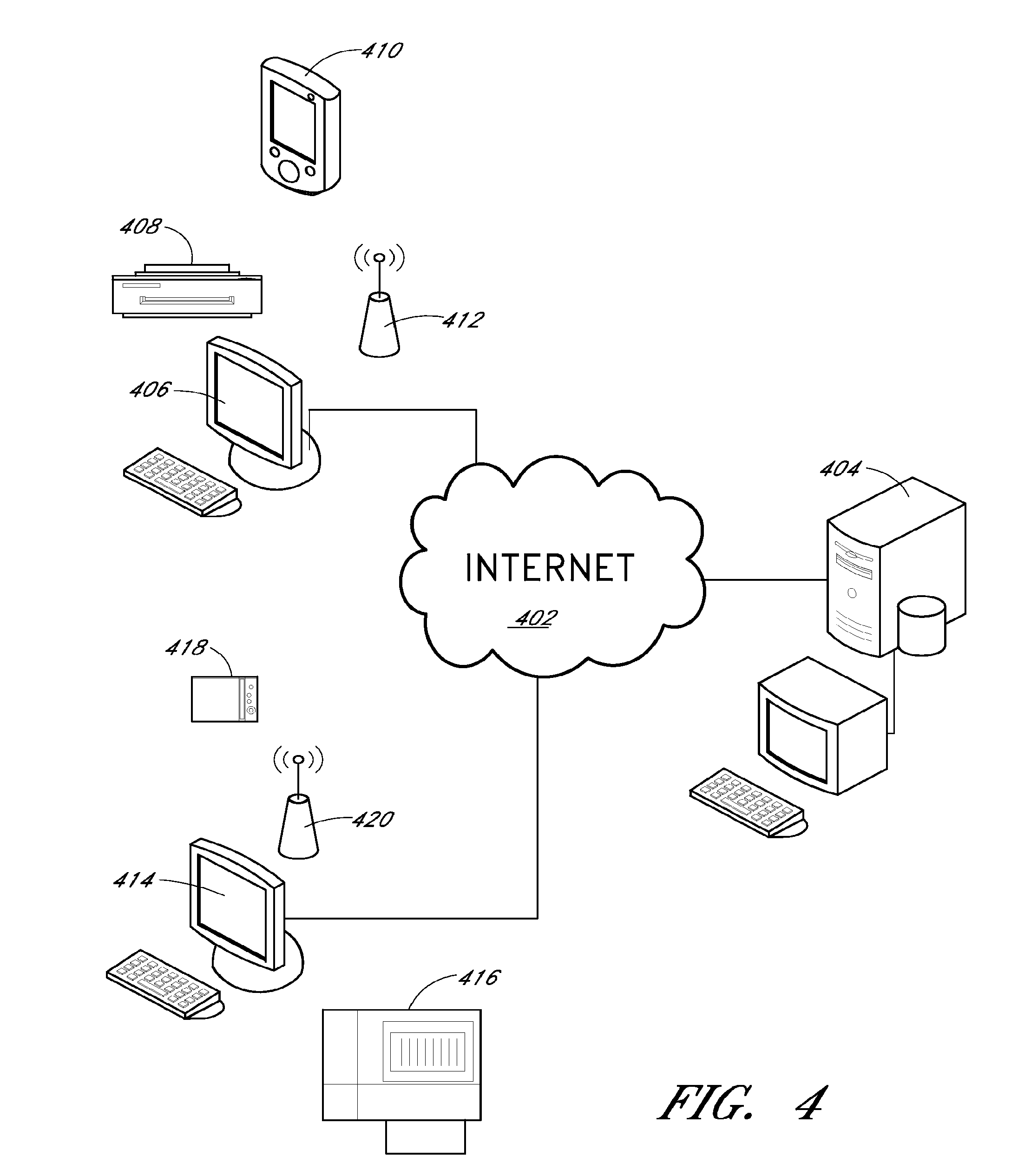
FIG. 4 illustrates an example networked configuration. In this example, a system 404, which may host an online commerce website (e.g., a shopping website) is coupled to a network 402 (the Internet in this example). The system 404 includes a Web server that hosts user interfaces for providing network settings, such as those described above with reference to FIGS. 2A-C. In addition, the system 404 in this example hosts a barcode generator that converts data provided by the user via the user interfaces (and optionally other data as well, such as Uniform Resource Locaters) into barcodes. The system can include a user database storing user registration information (e.g., user contact information, payment information, etc.), user preferences, target device identifiers, user specified network settings, barcode information, order histories, pending orders, electronic catalogs including item information (e.g., name, cost, type, etc.), and/or other information.
User terminals 406, 414 (in this example, personal computers associated with two different users and located in different locations), access the system 404 via the Internet 402. The terminals 406, 414 in this example include full keyboards (including a key for each letter and for the numbers 0-9, and well as keys for certain punctuations), displays, local memory (e.g., a hard disk drive and/or FLASH memory, RAM, etc.), and network interfaces (e.g., wired and/or wireless network interfaces). As similarly discussed above, the terminals 406, 414 can be used to access user interfaces, enter data, and receive communications provided by the system 404. The terminals 406, 414 may be equipped with browsers to access Web sites. For example, the terminals can display a barcode generated by the system 404 and provided via a webpage or via email. The terminals 406, 414 are connected to corresponding printers 408, 416, which can be used to print the barcodes.
Wireless network access points 412, 420 provide wireless the target devices access to an Internet connection.
Target devices 410 (a touch screen portable personal digital assistant in this example) and 418 (a video game system in this example) include or are coupled to optical scanners which can be used to scan the barcodes, as discussed above.
FIG. 5 illustrates another example target device. The device includes an integral barcode scanner 502, dedicated buttons 504, 506 (such as the fixed function buttons discussed above with respect to FIGS. 3A-C), programmable function buttons (such as the changeable function buttons discussed above with respect to FIGS. 3A-C), a display 512, and an antenna 514. The device may include a processor, memory (e.g., a magnetic disk, FLASH memory, and/or RAM), a wired and/or wireless network interface, and an interface to removable memory. The processor may be coupled to the memory, network interface(s), display, and buttons. The device memory may store programs, user interfaces and data, such as a product database. A program may be use optically read data (after being converted to digital data) to implement corresponding device settings (e.g., network settings, display settings, energy conservation settings).
Thus, described above are efficient methods and systems for performing device configuration, including network configuration, even when certain user interface devices (e.g., a large screen, a full keyboard) are lacking.
It should be understood that certain variations and modifications of this invention would suggest themselves to one of ordinary skill in the art. The scope of the present invention is not to be limited by the illustrations or the foregoing descriptions thereof.
* * * * *
D00000
D00001
D00002
D00003
D00004
D00005
D00006
D00007
D00008
D00009
D00010
XML
uspto.report is an independent third-party trademark research tool that is not affiliated, endorsed, or sponsored by the United States Patent and Trademark Office (USPTO) or any other governmental organization. The information provided by uspto.report is based on publicly available data at the time of writing and is intended for informational purposes only.
While we strive to provide accurate and up-to-date information, we do not guarantee the accuracy, completeness, reliability, or suitability of the information displayed on this site. The use of this site is at your own risk. Any reliance you place on such information is therefore strictly at your own risk.
All official trademark data, including owner information, should be verified by visiting the official USPTO website at www.uspto.gov. This site is not intended to replace professional legal advice and should not be used as a substitute for consulting with a legal professional who is knowledgeable about trademark law.