Radio transmission device and method
Futagi , et al.
U.S. patent number 10,225,042 [Application Number 15/689,503] was granted by the patent office on 2019-03-05 for radio transmission device and method. This patent grant is currently assigned to Godo Kaisha IP Bridge 1. The grantee listed for this patent is Godo Kaisha IP Bridge 1. Invention is credited to Sadaki Futagi, Daichi Imamura, Seigo Nakao, Tomofumi Takata.


View All Diagrams
| United States Patent | 10,225,042 |
| Futagi , et al. | March 5, 2019 |
Radio transmission device and method
Abstract
A radio transmitting device and method enables reduction of an increase of CGI memories for the control channel and an improvement of the throughput of the data channel. When multiplex transmission through the control channel and the data channel is carried out and when adaptive modulation is applied to both channels, an MCS selecting section is provided with one CQI table for the data channel and CQI tables for the control channel, and a table selecting MCS determining section selects one of the tables depending on the transmission bandwidth of the terminal and determines the MCS of the control channel while looking up the selected CQI table.
| Inventors: | Futagi; Sadaki (Ishikawa, JP), Imamura; Daichi (Beijing, CN), Nakao; Seigo (Kanagawa, JP), Takata; Tomofumi (Ishikawa, JP) | ||||||||||
|---|---|---|---|---|---|---|---|---|---|---|---|
| Applicant: |
|
||||||||||
| Assignee: | Godo Kaisha IP Bridge 1 (Tokyo,
JP) |
||||||||||
| Family ID: | 40852868 | ||||||||||
| Appl. No.: | 15/689,503 | ||||||||||
| Filed: | August 29, 2017 |
Prior Publication Data
| Document Identifier | Publication Date | |
|---|---|---|
| US 20170366297 A1 | Dec 21, 2017 | |
Related U.S. Patent Documents
| Application Number | Filing Date | Patent Number | Issue Date | ||
|---|---|---|---|---|---|
| 15258739 | Sep 7, 2016 | 9787427 | |||
| 14509955 | Oct 11, 2016 | 9467248 | |||
| 13686598 | Nov 25, 2014 | 8897389 | |||
| 13325969 | Dec 25, 2012 | 8340212 | |||
| 12811509 | Jan 17, 2012 | 8098759 | |||
| PCT/JP2008/004009 | Dec 26, 2008 | ||||
Foreign Application Priority Data
| Jan 4, 2008 [JP] | 2008-000199 | |||
| Current U.S. Class: | 1/1 |
| Current CPC Class: | H04L 1/0021 (20130101); H04W 72/0413 (20130101); H04L 1/0005 (20130101); H04L 1/0016 (20130101); H04L 1/0013 (20130101); H04L 1/0035 (20130101); H04L 1/0004 (20130101); H04L 5/0057 (20130101); H04L 1/001 (20130101); H04L 1/0011 (20130101); H04L 5/0055 (20130101); H04L 1/0026 (20130101); H04W 88/02 (20130101); Y02D 30/50 (20200801); H04L 2001/0098 (20130101); H04W 28/18 (20130101); H04W 72/04 (20130101) |
| Current International Class: | H04L 1/00 (20060101); H04L 5/00 (20060101); H04W 72/04 (20090101); H04W 28/18 (20090101); H04W 88/02 (20090101) |
References Cited [Referenced By]
U.S. Patent Documents
| 8098759 | January 2012 | Futagi et al. |
| 8340212 | December 2012 | Futagi et al. |
| 8812048 | August 2014 | Shin et al. |
| 9036516 | May 2015 | Kent et al. |
| 2004/0196801 | October 2004 | Hiramatsu |
| 2005/0105483 | May 2005 | Uehara et al. |
| 2006/0093024 | May 2006 | Pietraski et al. |
| 2007/0082619 | April 2007 | Zhang et al. |
| 2008/0132172 | June 2008 | Yoshii et al. |
| 2008/0153425 | June 2008 | Heo et al. |
| 2008/0188184 | August 2008 | Nogami et al. |
| 2008/0233964 | September 2008 | McCoy et al. |
| 2008/0268862 | October 2008 | Kent et al. |
| 2009/0010211 | January 2009 | Sumasu et al. |
| 2009/0059844 | March 2009 | Ko et al. |
| 2009/0109999 | April 2009 | Kuri et al. |
| 2009/0185638 | July 2009 | Imamura et al. |
| 2009/0213955 | August 2009 | Higuchi et al. |
| 2009/0232101 | September 2009 | Papasakellariou et al. |
| 2009/0290541 | November 2009 | Nishio |
| 2010/0027450 | February 2010 | Montojo et al. |
| 2010/0103899 | April 2010 | Kwak et al. |
| 1 914 948 | Apr 2008 | EP | |||
| 2003-283471 | Oct 2003 | JP | |||
| 2006-211017 | Aug 2006 | JP | |||
| 2007-150906 | Jun 2007 | JP | |||
| 10-2007-0000807 | Jan 2007 | KR | |||
| 2006/052448 | May 2006 | WO | |||
| 2006/059565 | Jun 2006 | WO | |||
| 2006/082761 | Aug 2006 | WO | |||
| 2006/098105 | Sep 2006 | WO | |||
| 2006/106613 | Oct 2006 | WO | |||
| 2007/020996 | Feb 2007 | WO | |||
| 2007/037412 | Apr 2007 | WO | |||
| 2007/136002 | Nov 2007 | WO | |||
| 2008/078733 | Jul 2008 | WO | |||
Other References
|
"3.sup.rd Generation Partnership Project; Technical Specification Group Radio Access Network; Evolved Universal Radio Access (E-UTRA), Multiplexing and channel coding (Release 8)," Technical Specification, 3GPP TS 36.212 V8.0.0, Sep. 2007, 30 pages. cited by applicant . Ad hoc chairman, "Notes from uplink control signaling discussion," R1-073842, Agenda Item: 7.2.2, TSG-RAN WG1 #50, Athens, Greece, Aug. 20-24, 2007, 3 pages. cited by applicant . Change Request, "RM1 transparent for HS-SCCH-less operation," R1-073344, 3GPP TSG-RAN WG1 #50, Athens, Greece, Aug. 20-24, 2007, 3 pages. cited by applicant . Freescale Semiconductor, "Data Puncturing and Piggy-backed Control," R1-071727, Agenda Item: 7.11.1, 3GPP TSG-RAN1 #48bis, St. Julians, Malta, Mar. 26-30, 2007, 3 pages. cited by applicant . International Search Report, dated Apr. 7, 2009, for International Application No. PCT/JP2008/004009, 4 pages. cited by applicant . Motorola, "Multiplexing of Uplink Control Signaling with Data," R1-070777, Agenda Item: 6.9.1, 3GPP TSG RAN1 #48, St. Louis, USA, Feb. 12-16, 2007, 3 pages. cited by applicant . Motorola, "UL L1/L2 Control Signals with Data: Multiplexing Detail," R1-073388, Agenda Item: 7.2.4, 3GPP TSG RAN1 #50, Athens, Greece, Aug. 20-24, 2007, 3 pages. cited by applicant . Search Report, dated Sep. 13, 2013, for corresponding Chinese Application No. 2008801215677, 3 pages. cited by applicant . Qualcomm Europe, "Rate matching details for control and data multiplexing," R1-073269, Agenda Item: 7.3, An5xter73GPP TSG-RAN WG1 #50, Athens, Greece, Aug. 20-24, 2007, 6 pages. cited by applicant . Nokia, "Update to 64QAM CQI tables," R1-073334, Agenda Item: 6, 3GPP TSG-RAN WG1 Meeting #50, Athens, Greece, Aug. 20-24, 2007, 2 pages. cited by applicant. |
Primary Examiner: Cho; Hong S
Attorney, Agent or Firm: Seed IP Law Group LLP
Claims
The invention claimed is:
1. A communication apparatus comprising: coding circuitry which, in operation, codes a first form of control data using a first coding scheme that is obtained based on multiplying a first value related to a first modulation and coding scheme (MCS) and a first offset value for the first form of control data, and codes a second form of control data using a second coding scheme that is obtained based on multiplying a second value related to a second MCS and a second offset value for the second form of control data; and a transmitter, coupled to the coding circuitry, which, in operation, transmits first data and the first form of control data coded with the first coding scheme, and transmits second data and the second form of control data coded with the second coding scheme.
2. The communication apparatus according to claim 1 wherein the first coding scheme used to code the first form of control data is different from the second coding scheme used to code the second form of control data.
3. The communication apparatus according to claim 1 wherein the first value related to the first MCS and the first offset value are multiplied regardless of the first value related to the first MCS, or the second value related to the second MCS and second first offset value are multiplied regardless of the second value related to the second MCS.
4. The communication apparatus according to claim 3 wherein the first form of control data includes an ACK/NACK and the first value related to the first MCS and the first offset value are multiplied regardless of the first value related to the first MCS, and the second form of control data includes a channel quality indicator (CQI) and the second value related to the second MCS and the second offset value are multiplied regardless of the second value related to in the second MCS.
5. The communication apparatus according to claim 1 wherein at least one of the first value related to the first MCS and the second value related to the second MCS includes a value related to a coding rate.
6. The communication apparatus according to claim 1 wherein the first value related to the first MCS and the first offset value are multiplied regardless of the first value related to the first MCS, and wherein the first value related to the first MCS includes a value related to a coding rate.
7. The communication apparatus according to claim 1 wherein the first form of control data includes an ACK/NACK, and the second form of control data includes a channel quality indicator (CQI).
8. The communication apparatus according to claim 1 wherein the transmitter, in operation, multiplexes and transmits the first data and the first form of control data coded with the first coding scheme, and multiplexes and transmits the second data and the second form of control data coded with second first coding scheme.
9. The communication apparatus according to claim 1, further comprising a receiver which, in operation, receives control information, wherein the coding circuitry, in operation, determines at least one of the first value of the first MCS and the second value related to the second MCS based on the received control information.
10. The communication apparatus according to claim 9 wherein the control information includes a channel quality indicator (CQI).
11. The communication apparatus according to claim 1 wherein the first offset value is obtained by multiplying a base offset value with a first scale value for the first form of control data, or the second offset value is obtained by multiplying the base offset value with a second scale value for the second form of control data.
12. The communication apparatus according to claim 1 wherein at least one of the first offset value and the second the offset value is associated with a parameter of the communication apparatus.
13. The communication apparatus according to claim 12 wherein the parameter is a transmission bandwidth parameter, a scheduling scheme parameter, a frequency hopping parameter, or a number of retransmissions parameter.
14. A non-transitory processor-readable medium storing software that, when executed by one or more processors, causes the one or more processors to: code a first form of control data using a first coding scheme that is obtained based on multiplying a first value related to a first modulation and coding scheme (MCS) and a first offset value for the first form of control data; transmit first data and the first form of control data coded with the first coding scheme; code a second form of control data using a second coding scheme that is obtained based on multiplying a second value related to a second MCS and a second offset value for the second form of control data; and transmit second data and the second form of control data coded with the second coding scheme.
15. The non-transitory processor-readable medium of claim 14 wherein the first coding scheme used to code the first form of control data is different from the second coding scheme used to code the second form of control data.
16. The non-transitory processor-readable medium of claim 15 wherein the first offset value is multiplied regardless of the first value related to the first MCS, or the second offset value is multiplied regardless of the second value related to the second MCS.
17. The non-transitory processor-readable medium of claim 14 wherein the first form of control data includes an ACK/NACK, and the second form of control data includes a channel quality indicator (CQI).
18. The non-transitory processor-readable medium of claim 14 wherein the software, when executed by the one or more processors, causes the one or more processors to multiplex and output the first data and the first form of control data coded with the first coding scheme, and to multiplex and output the second data and the second form of control data coded with the second coding scheme.
19. The non-transitory processor-readable medium of claim 14 wherein the software, when executed by the one or more processors, causes the one or more processors to determine at least one of the first value of the first MCS and the second value related to the second MCS based on received control information.
20. The non-transitory processor-readable medium of claim 19 wherein the control information includes a channel quality indicator (CQI).
21. The non-transitory processor-readable medium of claim 14 wherein the first offset value is obtained by multiplying a base offset value with a first scale value for the first form of control data, or the second offset value is obtained by multiplying the base offset value with a second scale value for the second form of control data.
22. The non-transitory processor-readable medium of claim 14 wherein at least one of the first offset value and the second offset value is associated with a parameter of the communication apparatus.
23. The non-transitory processor-readable medium of claim 22 wherein the parameter is a transmission bandwidth parameter, a scheduling scheme parameter, a frequency hopping parameter, or a number of retransmissions parameter.
24. The non-transitory processor-readable medium of claim 14 wherein the first form of control data includes an ACK/NACK and the first value related to the first MCS and the first offset value are multiplied regardless of the first value related to the first MCS, and the second form of control data includes a channel quality indicator (CQI) and the second value related to the second MCS and the second offset value are multiplied regardless of the second value related to the second MCS.
25. The non-transitory processor-readable medium of claim 14 wherein at least one of the first value related to the first MCS and the second value related to the second MCS includes a value related to a coding rate.
26. The non-transitory processor-readable medium of claim 14 wherein the first value related to the first MCS and the first offset value are multiplied regardless of the first value related to the first MCS, and wherein the first value related to the first MCS includes a value related to a coding rate.
Description
TECHNICAL FIELD
The present disclosure relates to a radio transmitting apparatus and a radio transmission method that are used in communication systems employing an adaptive modulation.
RELATED ART
Presently, in 3GPP RAN LTE (Long Term Evolution) in uplink, single carrier transmission is gaining attention to achieve a low PAPR (Peak to Average Power Ratio). Further, studies are conducted for a scheme to perform "adaptive modulation (AMC: Adaptive Modulation and Coding)" for selecting a user-specific MCS (Modulation and Coding Scheme) pattern according to a CQI (Channel Quality Indicator) of users to achieve high throughput.
Further, to adopt adaptive modulation and hybrid ARQ to a downlink data channel, in uplink channel, downlink CQI information and downlink ACK/NACK information are transmitted in a control channel.
FIG. 1 shows an MCS table a terminal uses for adaptive modulation for a data channel and so on (hereinafter, "CQI table") (see, for example, Non-Patent Document 1). Here shows, based on a CQI value, that is, based on channel quality information including an SNR, various modulation schemes and coding rates are read from the table shown in FIG. 1 to determine an MCS for a data channel.
Further, studies are underway to transmit an uplink data channel and an uplink control channel in the same frame, and, furthermore, to determine an MCS for the control channel at the same time as an MCS for the data channel, using a CQI determining the MCS for the data channel (see, for example, Non-Patent Document 2).
Accordingly, similar to the MCS for a control channel, various modulation schemes and coding rates (hereinafter SE: Spectral Efficiency, and SE is defined as the number of bits per symbol.times.coding rate) are determined in accordance with CQIs. FIG. 2 shows a concrete example of a CQI table in which associations between data channel SE and control channel SE are shown. Hybrid ARQ is not adopted to this control channel. Accordingly, control channel SE is set up robust with respect to CQIs that is, the SE is set up to be low such that required quality is satisfied even in a poor reception environment. Non-Patent Document 1: R1-073334, Nokia, "Update to 64QAM CQI tables," 3GPP TSG RAN WG1 Meeting #50, Athens, Greece, Aug. 20-24, 2007 Non-Patent Document 2: 3GPP TS36.212 V8.0.0
BRIEF SUMMARY
However, with the above-described technique, in situations where the reception environment is not poor, SE read from the table fully satisfies required quality for a control channel, and therefore wasted radio resources are provided to use the control channel. As a result, there is a problem of decreasing data channel throughput.
This case will be explained as an example shown in FIG. 3. As shown in FIG. 3, when a data channel and a control channel are multiplexed and transmitted in the same frame, the size of resources that can be used is determined. When the reception environment is not poor, SE that fully satisfies the required quality for a control channel is set, and therefore control channel resources are wasted. However, these wasted resources cannot be used as data channel resources, and therefore data channel throughput decreases.
An embodiment provides a radio transmitting apparatus and a radio transmission method that facilitates improvement of data channel throughput.
The radio transmitting apparatus of an embodiment adopts the configuration including: a modulation and coding scheme selection section that switches associations between channel quality indicators and modulation and coding schemes according to a parameter of a radio communication terminal apparatus, to determine a modulation and coding scheme of a control channel based on the associations after the switching; and a coding and modulation section that encodes and modulates control data by the determined modulation and coding scheme.
The radio transmission method of an embodiment includes: a switching step of switching associations between channel quality indicators and modulation and coding schemes according to a parameter of radio communication terminal apparatus; a modulation and coding scheme selection step of determining a modulation and coding scheme of a control channel based on the associations after the switching; and a coding and modulation step of encoding and modulating control data by the determined modulation and coding scheme.
An embodiment provides an advantage of improving data channel throughput.
BRIEF DESCRIPTION OF DRAWINGS
FIG. 1 shows a CQI table a terminal uses for adaptive modulation of a data channel and so on;
FIG. 2 shows a concrete example of a CQI table showing associations between data channel SE and control channel SE;
FIG. 3 illustrates how a data channel and a control channel are multiplexed and transmitted in the same frame;
FIG. 4 shows the relationships between the received SNRs and the SE when required BLER of a data channel is 10%;
FIG. 5 shows the relationships between the received SNRs and the SE when required BER of ACK/NACK channels is 0.01%;
FIG. 6 is a block diagram showing the configuration of a radio communication terminal apparatus according to Embodiment 1 of the present disclosure;
FIG. 7 is a block diagram showing an internal configuration of the MCS selection section shown in FIG. 6;
FIG. 8 shows an example of a control channel CQI table;
FIG. 9 shows another example of a control channel CQI table;
FIG. 10 shows a block diagram showing the internal configuration of the MCS selection section according to Embodiment 2 of the present disclosure;
FIG. 11 shows an example of an offset lookup table;
FIG. 12 shows an example of a control channel CQI table;
FIG. 13 shows a CQI table according to Embodiment 3 of the present disclosure; and
FIG. 14 shows a CQI table according to Embodiment 4 of the present disclosure.
DETAILED DESCRIPTION
Now, embodiments of the present disclosure will be described in detail with reference to the accompanying drawings. FIG. 4 shows the relationships between the received SNRs and the SE (Spectral Efficiency) acquired from simulation results when required BLER of a data channel is 10%. Further, FIG. 5 shows the relationships between the received SNRs and the SE when required BER of ACK/NACK of control channels is 0.01%. According to the present embodiment, although the difference in a received SNR between performance with AWGN and SE without frequency hopping (a 180 kHz bandwidth) is 5 dB in a data channel, the difference is 9 dB in a control channel, and therefore the focus is placed upon severe deterioration of the control channel performance. That is, the focus is placed upon a significant difference between the data channel performance and the control channel performance in specific conditions.
Embodiment 1
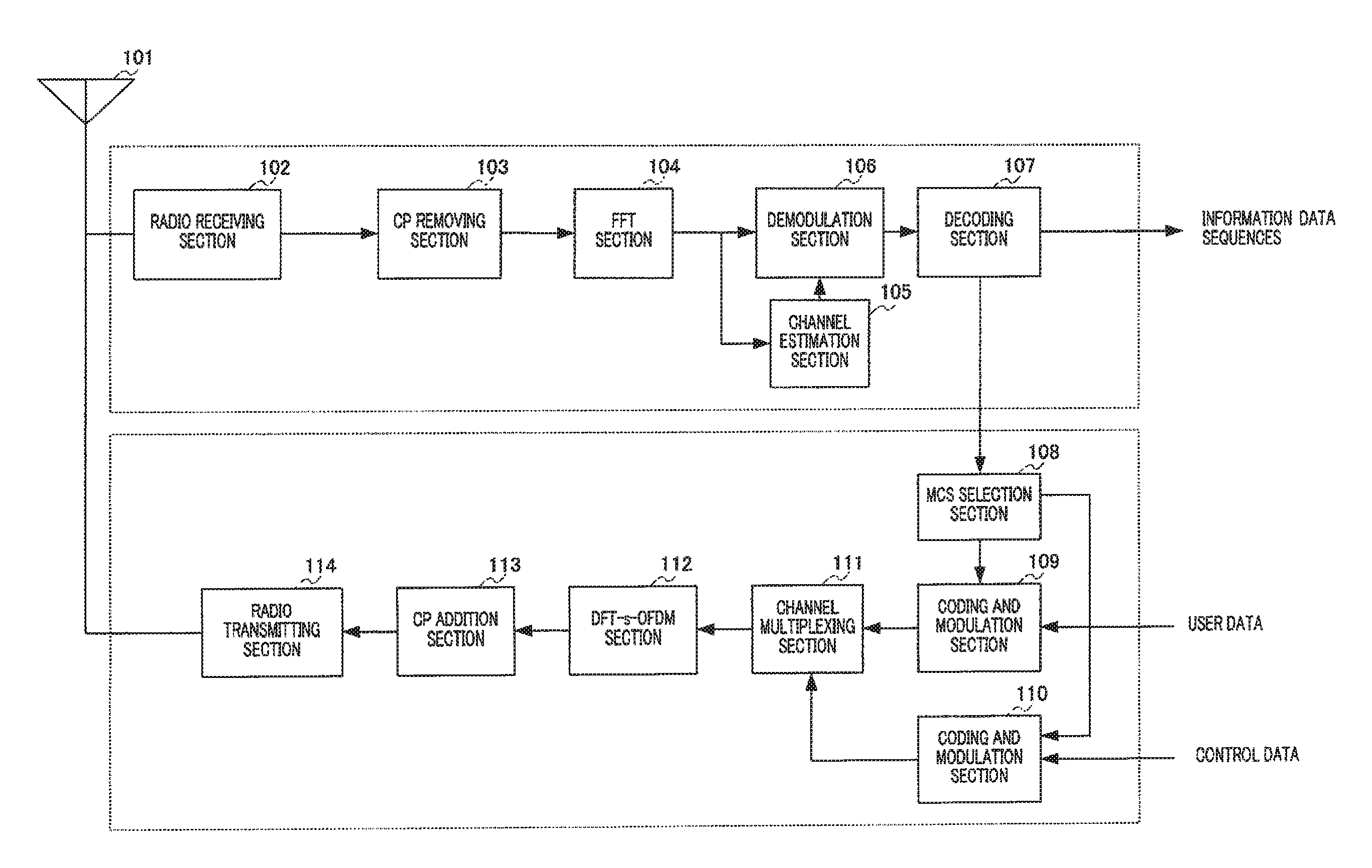
FIG. 6 is block diagram showing the configuration of a radio communication terminal apparatus according to Embodiment 1 of the present disclosure. Now, the configuration of the radio communication terminal apparatus will be explained with reference to FIG. 6. Radio receiving section 102 converts a signal received via antenna 101 to a base band signal, and outputs the baseband signal to CP removing section 103.
CP removing section 103 removes the CP (Cyclic Prefix) from the baseband signal outputted from radio receiving section 102, and outputs the resulting signal to FFT section 104.
FFT section 104 performs an FFT (Fast Fourier Transform) on the time-domain signal outputted from CP removing section 103, and outputs the resulting frequency-domain signal to channel estimation section 105 and demodulation section 106.
Channel estimation section 105 estimates a channel environment of the received signal using the pilot signal included in the signal outputted from FFT section 104, and outputs the estimation result to demodulation section 106.
Based on the channel environment estimation result of the outputted from channel estimation section 105, demodulation section 106 performs channel compensation for a signal acquired by removing control information such as the pilot signal from the received signal outputted from FFT section 104, that is, performs channel compensation for data information. Further, demodulation section 106 demodulates the signal after the channel compensation based on the same MCS as the MCS used in the base station of the communicating party, and outputs the demodulated signal to decoding section 107.
Decoding section 107 performs error correction for the demodulated signal outputted from demodulation section 106, and extracts information data sequences, CQI information and bandwidth information from the received signal. The CQI information and the bandwidth information are outputted to MCS selection section 108.
MCS selection section 108 having a CQI table (described later) reads from the CQI table an MCS pattern associated with the CQI information outputted from decoding section 107, and determines the read MCS pattern as the MCS for a data channel (MCS 1). Further, based on the CQI information and the bandwidth information outputted from decoding section 107, MCS selection section 108 determines an MCS pattern for the control channel (MCS 2) with reference to a plurality of CQI tables (described later). The determined MCS 1 is outputted to coding and modulation section 109 and MCS 2 is outputted to coding and modulation section 110.
Coding and modulation section 109 encodes and modulates user data received as input (transmission data sequences) based on MCS 1 outputted from MCS selection section 108, to generate data channel transmission data. The generated transmission data for the data channel is outputted to channel multiplexing section 111.
Coding and modulation section 110 encodes and modulates control data received as input based on MCS 2 outputted from MCS selection section 108, to generate control channel transmission data. The generated transmission data for the control channel is outputted to channel multiplexing section 111.
Channel multiplexing section 111 performs time-division multiplexing of the transmission data for the data channel outputted from coding and modulation section 109 and the transmission data for the control channel outputted from coding and modulation section 110. The multiplexed transmission data is outputted to DFT-s-OFDM section 112.
DFT-s-OFDM section 112 performs a discrete Fourier transform (DFT) on the transmission data outputted from channel multiplexing section 111 and performs time-frequency transform on the data of frequency components, to acquire a frequency-domain signal. Then, after the frequency-domain signal is mapped to transmission subcarriers, the mapped frequency-domain signal is subject to an IFFT (Inverse Fast Fourier Transform) processing, to be transformed to a time-domain signal. The acquired time-domain signal is outputted to CP addition section 113.
CP addition section 113 adds CPs to the frames in the transmission data sequences outputted from DFT-s-OFDM section 112 by duplicating data at the tail of each frame and by adding the duplicated data to the beginning of each frame, and outputs the transmission data with CPs to radio transmitting section 114.
Radio transmitting section 114 frequency-converts the baseband signal outputted from CP addition section 113 to a radio frequency band signal, and transmits the converted signal via antenna 101.
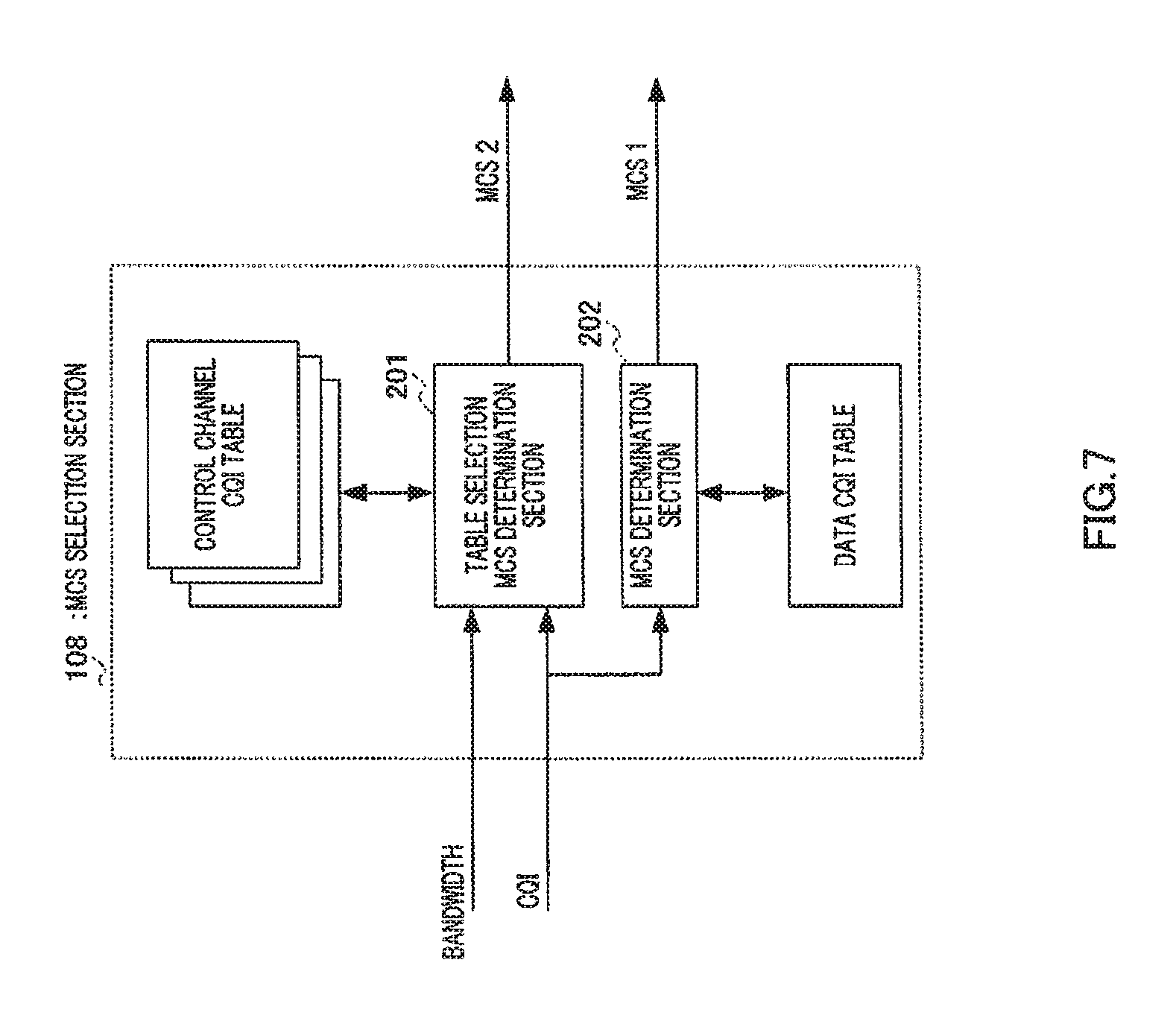
FIG. 7 is a block diagram showing an internal configuration of MCS selection section 108 shown in FIG. 6. Based on a CQI received as input, table selection MCS determination section 201 determines MCS 2 for the control channel with reference to the CQI table corresponding to the bandwidth among the control channel CQI tables shown in FIG. 8.
Based on a CQI received as input, MCS determination section 202 determines MCS 1 for the data channel with reference to the data CQI table.
FIG. 8 shows an example of a control channel CQI table. Here, table 1 is the CQI table for a 500 kHz bandwidth or below, and table 2 is the CQI table for more than a 500 kHz bandwidth. Further, with the same CQIs, SE in table 1 is set up lower than SE in table 2. When the bandwidth is narrow as 500 kHz, that is, when frequency diversity effect is small, lower SE is selected. On the other hand, when frequency diversity effect is significant, higher SE is selected than the SE in table 1. Accordingly, when the frequency diversity effect is significant, few control signal resources make it possible to satisfy the required quality for the control channel compared in a case where diversity effect is small, so that it is possible to increase the amount of resources used for the data channel.
In this way, according to Embodiment 1, when a data channel and a control channel are multiplexed and transmitted and adaptive modulation is applied to both channels, by providing one data channel CQI table and a plurality of control channel CQI tables, switching between a plurality of tables in accordance with a transmission bandwidth of a terminal, and determining the MCS for the control channel, it is possible to determine an MCS appropriate for the bandwidth and allocate radio resources used for the control channel adequately, thereby increasing radio resources used for the data channel. This makes it possible to improve data channel throughput.
Although a case has been explained with the present embodiment as an example where a CQI table is selected based only on the transmission bandwidth, as shown in FIG. 9, it is equally possible to select four CQI tables based on data channel scheduling methods in addition to a bandwidth. When persistent scheduling is used for a data channel, a low CQI is reported to make the MCS for the data channel robust. In this case, it is possible to increase the amount of resources used for the data channel by taking into account the difference in CQI between two kinds of scheduling, that is, normal scheduling (i.e. dynamic scheduling) and persistent scheduling, by configuring a plurality of control channel CQI tables and making the MCS and resources of use of the control channel adequate.
Embodiment 2
The configuration of a radio communication terminal apparatus according to Embodiment 2 of the present disclosure is the same as shown in FIG. 6 of Embodiment 1, this embodiment will be explained with reference to FIG. 6, and the overlapping explanation will be omitted.
FIG. 10 is a block diagram showing the internal configuration of MCS selection section 108 according to Embodiment 2 of the present disclosure. CQI offset MCS determination section 301 calculates a control channel CQI using an offset lookup table shown in FIG. 11, CQI information and equation 1. Control channel CQI=CQI+.SIGMA.offset[condition] (Equation 1)
Further, based on that control channel CQI, CQI offset MCS determination section 301 determines MCS 2 for the control channel with reference to the control channel CQI table shown in FIG. 12.
FIG. 11 shows an example of an offset lookup table. Here, when the data channel scheduling method is dynamic scheduling, the offset is zero, and when the data channel scheduling method is persistent scheduling, the offset is two. In this case, offsets are provided by taking into account of CQI differences between two kinds of scheduling, that is, between normal scheduling (i.e. dynamic scheduling) and persistent scheduling.
Further, the offset is zero when the data channel is used with frequency hopping, and the offset is -4 when the bandwidth is 1 RB (resource block) without frequency hopping. When frequency diversity effect is small, for example, frequency hopping is not adopted in a frame and transmission is performed in a narrow band, the offsets are provided so as to select a lower MCS. This is because the relatively small number of bits is transmitted and coding gain is less likely to be acquired. By taking into account of the above reason, offsets are provided according to bandwidths.
Furthermore, the offset is zero when a data channel transmission is the first, and the offset is -2 upon retransmissions. Received quality is poorer than expected when a data channel is retransmitted. In such a case, received quality may deteriorate with regards to a control channel, and therefore an offset is provided so as to select a lower MCS.
As explained above, according to parameters of a terminal, such as a data scheduling method, a bandwidth, frequency hopping in frames, and the number of data channel retransmissions, it is possible to set up a more adequate MCS. Accordingly, it is possible to satisfy required quality for a control channel using adequate control channel resources, so that the amount of resources used for a data channel can be increased.
FIG. 12 is an example of a control channel CQI table. Here, in addition to SE for 0 to 30 CQIs in a lookup table, lower SE for -1 to -10 CQIs and higher SE for 31 to 37 are newly set. Here, the lower SE part is mainly used when an offset is negative, and the higher SE part is mainly used when an offset is positive.
In this way, according to Embodiment 2, when a data channel and a control channel are multiplexed and transmitted and adaptive modulation is applied to both channels, one data channel CQI table, one control channel CQI table in series formed in a larger size than that data channel CQI table and an offset lookup table formed with parameters of a terminal are provided to determine the MCS for the control channel by a CQI found by adding all the amounts of offsets read from a offset lookup table to a data channel CQI, so that it is possible to prevent memory from increasing and improve data channel throughput.
Embodiment 3
FIG. 13 shows a CQI table according to Embodiment 3 of the present disclosure and by multiplying equation 1 by a scaling factor (N), a range set up in a lookup table can be bigger or smaller. A control channel CQI can be calculated using equation 2, Control channel CQI=floor(N.times.(CQI+.SIGMA.offset[condition])) (Equation 2) where N is a decimal.
To apply a case where a coding scheme varies like between an uplink CQI channel and ACK/NACK channels used in LTE, by changing the value, N, a control channel is applicable to different coding schemes. That is, an uplink CQI channel is applicable by only changing offset and value N, and ACK/NACK channels are applicable by an offset (N=1) only, so that it is possible to refer to MCSs of two kinds of control channels from the same CQI table.
In this way, according to Embodiment 3, a scaling factor is multiplied by a control channel CQI that is found by adding all the amounts of offsets, to calculate the new control channel CQI and to determine the MCS for the control channel, so that it is possible to prevent memory from increasing and improve data channel throughput even when there are control channels of different coding schemes.
Embodiment 4
FIG. 14 shows a CQI table according to Embodiment 4 of the present disclosure. The CQI table is calculated using equation 2 shown in Embodiment 3, where N is a decimal and, N=N_A(CQI<CQI_TH) and N=N_B(CQI>CQI_TH). Specifically, FIG. 14 shows a case where CQI_TH=3, N_A=0.7 and N_B=1.3. In this way, by changing a scaling factor, N, according to the magnitude of a CQI, it is possible to determine the MCS more accurately.
In this way, according to Embodiment 4, by multiplying by a scaling factor a control channel CQI found by adding all the amounts of offsets, changing the scaling factor according to the magnitude of the CQI, calculating a control channel CQI and determining the MCS for the control channel, even when there are control channels of different coding schemes, it is possible to prevent memory from increasing, and, furthermore, improve data channel throughput.
Although cases have been explained with Embodiments 3 and 4 where a primary linear process of multiplying N is adopted, a higher linear process may be adopted.
With the above embodiments, "drop" may be included in a control channel CQI table not so as to transmit a control channel using the lowest SE (MCS).
Further, with the above embodiments, when a calculated control channel CQI is outside the range of the control channel CQI table, it is possible to use the SE (MCSs) at both ends of the CQI table or use extrapolation.
Further, although cases have been described with the above embodiments as examples where embodiments of the present disclosure is configured by hardware, embodiments of the present disclosure can also be realized by software.
Each function block employed in the description of each of the aforementioned embodiments may typically be implemented as an LSI constituted by an integrated circuit. These may be individual chips or partially or totally contained on a single chip. "LSI" is adopted here but this may also be referred to as "IC," "system LSI," "super LSI," or "ultra LSI" depending on differing extents of integration.
Further, the method of circuit integration is not limited to LSIs, and implementation using dedicated circuitry or general purpose processors is also possible. After LSI manufacture, utilization of a programmable FPGA (Field Programmable Gate Array) or a reconfigurable processor where connections and settings of circuit cells within an LSI can be reconfigured is also possible.
Further, if integrated circuit technology comes out to replace LSI's as a result of the advancement of semiconductor technology or a derivative other technology, it is naturally also possible to carry out function block integration using this technology. Application of biotechnology is also possible.
INDUSTRIAL APPLICABILITY
The radio transmitting apparatus and radio transmission method according to at least one embodiment improves data channel throughput, and is applicable to, for example, mobile communication systems.
* * * * *
D00000
D00001
D00002
D00003
D00004
D00005
D00006
D00007
D00008
D00009
D00010
D00011
D00012

XML
uspto.report is an independent third-party trademark research tool that is not affiliated, endorsed, or sponsored by the United States Patent and Trademark Office (USPTO) or any other governmental organization. The information provided by uspto.report is based on publicly available data at the time of writing and is intended for informational purposes only.
While we strive to provide accurate and up-to-date information, we do not guarantee the accuracy, completeness, reliability, or suitability of the information displayed on this site. The use of this site is at your own risk. Any reliance you place on such information is therefore strictly at your own risk.
All official trademark data, including owner information, should be verified by visiting the official USPTO website at www.uspto.gov. This site is not intended to replace professional legal advice and should not be used as a substitute for consulting with a legal professional who is knowledgeable about trademark law.