Transmission and engine configuration
Bennett , et al.
U.S. patent number 10,221,869 [Application Number 15/465,824] was granted by the patent office on 2019-03-05 for transmission and engine configuration. This patent grant is currently assigned to Hydro-Gear Limited Partnership. The grantee listed for this patent is Hydro-Gear Limited Partnership. Invention is credited to Michael L. Bennett, Raymond Hauser.

| United States Patent | 10,221,869 |
| Bennett , et al. | March 5, 2019 |
Transmission and engine configuration
Abstract
A drive assembly having a housing forming an internal sump for a transmission, and an accumulator chamber formed in the housing and in fluid communication with the sump. A piston chamber in the housing is in fluid communication with the accumulator chamber. The transmission includes a pump, a pump running surface and an internal porting system in a center section, and a pump swash plate. A piston divides the piston chamber into first and second portions. The piston is biased by a spring force to pressurize hydraulic fluid in the piston chamber and thereby pressurize the hydraulic fluid in the internal sump when pressure in the piston chamber decreases below a set level. A second transmission may also be located in the housing.
| Inventors: | Bennett; Michael L. (Sullivan, IL), Hauser; Raymond (Sullivan, IL) | ||||||||||
|---|---|---|---|---|---|---|---|---|---|---|---|
| Applicant: |
|
||||||||||
| Assignee: | Hydro-Gear Limited Partnership
(Sullivan, IL) |
||||||||||
| Family ID: | 52822423 | ||||||||||
| Appl. No.: | 15/465,824 | ||||||||||
| Filed: | March 22, 2017 |
Related U.S. Patent Documents
| Application Number | Filing Date | Patent Number | Issue Date | ||
|---|---|---|---|---|---|
| 14690055 | Apr 17, 2015 | 9604536 | |||
| 13464236 | Apr 21, 2015 | 9010105 | |||
| 12201500 | Aug 29, 2008 | ||||
| 12183624 | Jul 31, 2008 | ||||
| 60953435 | Aug 1, 2007 | ||||
| Current U.S. Class: | 1/1 |
| Current CPC Class: | F16H 47/02 (20130101); B60K 17/14 (20130101); B60K 17/28 (20130101); F15B 11/17 (20130101); B62D 11/18 (20130101); B60K 17/105 (20130101); F16H 1/22 (20130101); F15B 1/24 (20130101); B60K 25/00 (20130101); B60K 17/043 (20130101); F15B 2211/625 (20130101); B60Y 2200/223 (20130101); F15B 2211/71 (20130101); F15B 2211/7058 (20130101); F16H 2047/025 (20130101); F15B 2211/615 (20130101) |
| Current International Class: | F15B 11/17 (20060101); F15B 1/24 (20060101); F16H 47/02 (20060101); B60K 17/10 (20060101); B60K 25/00 (20060101); B60K 17/04 (20060101); B60K 17/14 (20060101); B60K 17/28 (20060101); F16H 1/22 (20060101) |
References Cited [Referenced By]
U.S. Patent Documents
| 1539616 | May 1925 | Williams |
| 2914219 | November 1959 | Chiantelassa |
| 3279172 | October 1966 | Kudo et al. |
| 3748851 | July 1973 | Hause |
| 3765258 | October 1973 | Jespersen |
| 3775981 | December 1973 | Molly |
| 3922931 | December 1975 | Osujyo et al. |
| 4116292 | September 1978 | Todeschini et al. |
| 4129192 | December 1978 | Todeschini et al. |
| 4252508 | February 1981 | Forster |
| 4270408 | June 1981 | Wagner et al. |
| 4534271 | August 1985 | Forster |
| 4809796 | March 1989 | Yamaoka |
| 4819508 | April 1989 | Yamaoka et al. |
| 4887686 | December 1989 | Takei et al. |
| 4893524 | January 1990 | Ohashi |
| 4934214 | June 1990 | Otte |
| 4971535 | November 1990 | Okada et al. |
| 5040429 | August 1991 | Del Castillo |
| 5078222 | January 1992 | Hauser et al. |
| 5207060 | May 1993 | Sheets |
| 5247794 | September 1993 | Benson et al. |
| 5304043 | April 1994 | Shilling |
| 5354180 | October 1994 | Forster et al. |
| 5501578 | March 1996 | Skirde et al. |
| 5542307 | August 1996 | Hasegawa et al. |
| 5555727 | September 1996 | Hauser et al. |
| 5628189 | May 1997 | Hauser et al. |
| 5800134 | September 1998 | Hasegawa et al. |
| 5823285 | October 1998 | Tsuchihashi et al. |
| 5918691 | July 1999 | Ishii |
| 6022198 | February 2000 | Hoffmeister et al. |
| 6199380 | March 2001 | Ishii |
| 6301885 | October 2001 | Johnson et al. |
| 6332393 | December 2001 | Trimble |
| 6361282 | March 2002 | Wanschura et al. |
| 6363815 | April 2002 | Ishimaru et al. |
| 6382339 | May 2002 | Nemoto |
| 6425244 | July 2002 | Ohashi et al. |
| 6474218 | November 2002 | Saito et al. |
| 6487856 | December 2002 | Ohashi et al. |
| 6494686 | December 2002 | Ward |
| 6533695 | March 2003 | Pollman et al. |
| 6571894 | June 2003 | Ishimaru |
| 6601474 | August 2003 | Ishimaru |
| 6616563 | September 2003 | Inoue et al. |
| 6672058 | January 2004 | Langenfeld et al. |
| 6672843 | January 2004 | Holder et al. |
| 6682058 | January 2004 | Nemeth et al. |
| 6705840 | March 2004 | Hauser |
| 6736605 | May 2004 | Ohashi et al. |
| 6779615 | August 2004 | Boyer et al. |
| 6811510 | November 2004 | Langenfeld et al. |
| 6820403 | November 2004 | Umemoto |
| 6830116 | December 2004 | Ishimaru et al. |
| 6843056 | January 2005 | Langenfeld |
| 6877302 | April 2005 | Samejima et al. |
| 6957229 | October 2005 | Dyor |
| 6973783 | December 2005 | Hauser et al. |
| 6988580 | January 2006 | Ohashi et al. |
| 7028472 | April 2006 | Ohashi et al. |
| 7044259 | May 2006 | Stoll et al. |
| 7056101 | June 2006 | Hauser et al. |
| 7137250 | November 2006 | McCoy et al. |
| 7146810 | December 2006 | Hauser et al. |
| 7147810 | December 2006 | Reinhard et al. |
| 7162870 | January 2007 | Hauser |
| 7225617 | June 2007 | Langenfeld et al. |
| 7231765 | June 2007 | Kawamura |
| 7347047 | March 2008 | Hauser |
| 7367185 | May 2008 | McCoy et al. |
| 7370714 | May 2008 | Yasuda et al. |
| 7377105 | May 2008 | Raymond |
| 7392654 | July 2008 | Hauser et al. |
| 7455132 | November 2008 | Acharya et al. |
| 7536857 | May 2009 | Hauser et al. |
| 7621353 | November 2009 | Ishii et al. |
| 7640738 | January 2010 | Hauser |
| 7673712 | March 2010 | Iida |
| 7900447 | August 2011 | Hauser et al. |
| 8443598 | May 2013 | Hauser et al. |
| 9010105 | April 2015 | Bennett |
| 9604536 | March 2017 | Bennett |
| 2002/0189885 | December 2002 | Ruebusch et al. |
| 2007/0209457 | September 2007 | Irikura |
| 1473183 | Nov 2004 | EP | |||
| 2000009023 | Jan 2000 | JP | |||
| 2001146951 | May 2001 | JP | |||
| 2001263259 | Sep 2001 | JP | |||
| WO1999067532 | Dec 1999 | WO | |||
Other References
|
Dixie Chopper, Operation Manual, Cover Page and pp. 50-51, 60-61, 66, revision #5, 1998. cited by applicant . Non-Final Office Action dated Dec. 30, 2010 with respect to U.S. Appl. No. 12/183,624. cited by applicant . Notice of Allowance dated Jul. 7, 2010 with respect to U.S. Appl. No. 12/184,370. cited by applicant . Notice of Allowance dated Oct. 18, 2010 with respect to U.S. Appl. No. 12/184,370. cited by applicant. |
Primary Examiner: Lazo; Thomas E
Attorney, Agent or Firm: Neal, Gerber & Eisenberg LLP
Parent Case Text
RELATED APPLICATIONS
This application is a continuation of U.S. patent application Ser. No. 14/690,055, filed Apr. 17, 2015, which is a continuation of U.S. patent application Ser. No. 13/464,236 filed May 4, 2012, now U.S. Pat. No. 9,010,105, which is a continuation-in-part of U.S. patent application Ser. No. 12/201,500 filed on Aug. 29, 2008, now abandoned, which is a continuation-in-part of U.S. patent application Ser. No. 12/183,624 filed on Jul. 31, 2008, now abandoned, which claims priority to U.S. Pat. App. No. 60/953,435 filed on Aug. 1, 2007. These prior applications are incorporated by reference herein in their entirety.
Claims
The invention claimed is:
1. A drive assembly for use with hydraulic fluid, the drive assembly comprising: a housing forming an internal sump and comprising: an accumulator chamber formed in the housing and in fluid communication with the internal sump, and a piston chamber formed in the housing and in fluid communication with the accumulator chamber; a first transmission disposed in the internal sump and comprising: a first center section comprising a first pump running surface and a first motor running surface, and a first internal porting system connecting the first pump running surface to the first motor running surface; and a first pump disposed on the first pump running surface and a first motor disposed on the first motor running surface; a second transmission disposed in the internal sump and comprising: a second center section disposed in the internal sump and comprising a second pump running surface and a second motor running surface, and a second internal porting system connecting the second pump running surface to the second motor running surface; and a second pump disposed on the second pump running surface and a second motor disposed on the second motor running surface; and a piston disposed in the piston chamber and dividing the piston chamber into a first portion and a second portion, wherein the piston is biased by a spring force to pressurize the hydraulic fluid in the piston chamber and thereby pressurize the hydraulic fluid in the internal sump when a pressure of the hydraulic fluid in the piston chamber decreases below a set level.
2. The drive assembly of claim 1, further comprising a filter chamber formed in the housing and in fluid communication with the internal sump, and a filter disposed in the filter chamber.
3. The drive assembly of claim 1, wherein the internal sump comprises a plurality of chambers disposed in the housing, and all of the plurality of chambers are in fluid communication.
4. The drive assembly of claim 3, wherein the plurality of chambers comprises a first chamber in which the first transmission is disposed and a second chamber in which the second transmission is disposed, and a third chamber disposed generally between the first chamber and the second chamber.
5. The drive assembly of claim 4, further comprising a filter chamber formed in the housing and in fluid communication with the internal sump, and a filter disposed in the filter chamber.
6. The drive assembly of claim 5, wherein the piston chamber is located between the first chamber and the third chamber, and the filter chamber is located in the housing between the second chamber and the third chamber.
7. The drive assembly of claim 4, further comprising a power take off assembly disposed in the third chamber.
8. The drive assembly of claim 7, further comprising a valve mounted in the housing and operatively connected to the power take off assembly.
9. The drive assembly of claim 7, further comprising a filter chamber formed in the housing and in fluid communication with the internal sump, and a filter disposed in the filter chamber, wherein the piston chamber is located between the first chamber and the third chamber, and the filter chamber is located in the housing between the second chamber and the third chamber.
10. The drive assembly of claim 1, further comprising a first passage formed in the housing to connect the first internal porting system of the first center section to the accumulator chamber.
11. The drive assembly of claim 10, further comprising a second passage formed in the housing to connect the second internal porting system of the second center section to the accumulator chamber.
12. A drive assembly for use with a hydraulic fluid, the drive assembly comprising: a housing forming an internal sump and comprising: an accumulator chamber formed in the housing and in fluid communication with the internal sump, and a piston chamber formed in the housing and in fluid communication with the accumulator chamber; a transmission disposed in the internal sump and comprising: a center section comprising a pump running surface and an internal porting system; and a pump disposed on the pump running surface and a pump swash plate for adjusting the output of the pump; and a piston disposed in the piston chamber and dividing the piston chamber into a first portion and a second portion, wherein the piston is biased by a spring force to pressurize the hydraulic fluid in the piston chamber and thereby pressurize the hydraulic fluid in the internal sump when a pressure of the hydraulic fluid in the piston chamber decreases below a set level.
13. The drive assembly of claim 12, further comprising a filter chamber formed in the housing and in fluid communication with the internal sump, and a filter disposed in the filter chamber.
14. The drive assembly of claim 13, further comprising: a gear chamber disposed adjacent to the pump swash plate; a gear disposed in the gear chamber for driving an input shaft of the pump; and a port formed in the gear chamber for providing hydraulic fluid to the filter.
15. The drive assembly of claim 12, further comprising a power take off assembly disposed in the housing, and a valve mounted in the housing and operatively connected to the power take off assembly.
16. The drive assembly of claim 12, further comprising a passage formed in the housing to connect the internal porting system of the center section to the accumulator chamber.
17. A drive assembly comprising: a housing forming an internal sump for hydraulic fluid; a first transmission disposed in the internal sump and comprising: a first center section comprising a first pump running surface and a first motor running surface, and a first internal porting system connecting the first pump running surface to the first motor running surface; a first pump disposed on the first pump running surface and driven by a first pump shaft; a first motor disposed on the first motor running surface and driving a first motor output shaft; a first adjustable swash plate for adjusting the output of the first pump; a second transmission disposed in the internal sump and comprising: a second center section disposed in the internal sump and comprising a second pump running surface and a second motor running surface, and a second internal porting system connecting the second pump running surface to the second motor running surface; a second pump disposed on the second pump running surface and driven by a second pump shaft; a second motor disposed on the second motor running surface and driving a second motor output shaft; and a second adjustable swash plate for adjusting the output of the second pump; a filter chamber formed in the housing and in fluid communication with the internal sump; a filter disposed in the filter chamber; at least one gear chamber formed in the housing and a first gear disposed in the at least one gear chamber, wherein the first gear is engaged to and drives the first pump shaft; a pair of kidney ports formed in the at least one gear chamber to provide hydraulic fluid from the internal sump to the filter.
18. The drive assembly of claim 17, further comprising a second gear that is engaged to and rotates with the first gear, wherein the interaction of the first gear and the second gear provides pressurized hydraulic fluid to the filter.
19. The drive assembly of claim 17, further comprising a second gear that is engaged to and drives the second pump shaft, and a third gear that is engaged to and drives both the first gear and the second gear, and wherein the at least one gear chamber comprises a first gear chamber in which the first gear is disposed, a second gear chamber in which the second gear is disposed and a third gear chamber in which the third gear is disposed, and the interaction of the first gear and the second gear provides pressurized hydraulic fluid to the filter.
20. The drive assembly of claim 19, further comprising: an accumulator chamber formed in the housing and in fluid communication with the internal sump; a piston chamber formed in the housing and in fluid communication with the accumulator chamber; and a piston disposed in the piston chamber and dividing the piston chamber into a first portion and a second portion, wherein the piston is biased by a spring force to pressurize the hydraulic fluid in the piston chamber and thereby pressurize the hydraulic fluid in the internal sump when a pressure of the hydraulic fluid in the piston chamber decreases below a set level.
Description
BACKGROUND OF THE INVENTION
This invention relates to drive train configurations; in particular, drive train configurations that include a prime mover or engine and a transmission or transaxle assembly.
SUMMARY OF THE INVENTION
An engine and transmission assembly is disclosed herein. The transmission assembly may include gearing and axles. The engine is physically supported by the transmission assembly, forming a drive train assembly. The details of the invention are set forth below in connection with the detailed description of the embodiments.
A better understanding of the invention will be obtained from the following detailed descriptions and accompanying drawings, which set forth illustrative embodiments that are indicative of the various ways in which the principals of the invention may be employed.
BRIEF DESCRIPTION OF THE DRAWINGS
FIG. 1 is an elevation view of an embodiment of the present invention.
FIG. 2 is a perspective view of the transaxle portion of the embodiment shown in FIG. 1.
FIG. 3 is a perspective view of the embodiment shown in FIG. 2 with various elements, including external housings and tubes, removed for clarity.
FIG. 4 is a plan view of the central housing of the embodiment shown in FIG. 2.
FIG. 5 is a cross-sectional view along the line 5-5 in FIG. 4.
FIG. 6 is a cross-sectional view along the line 6-6 in FIG. 4.
FIG. 7 is a plan view of the transaxle portion mounted on a vehicle frame.
FIG. 8 is a partially sectioned view along the line 8-8 in FIG. 7, excluding the vehicle frame.
FIG. 9 is a cross-sectional view along the line 9-9 in FIG. 7.
FIG. 10 is an exploded perspective view of certain elements of the present invention.
DETAILED DESCRIPTION OF THE DRAWINGS
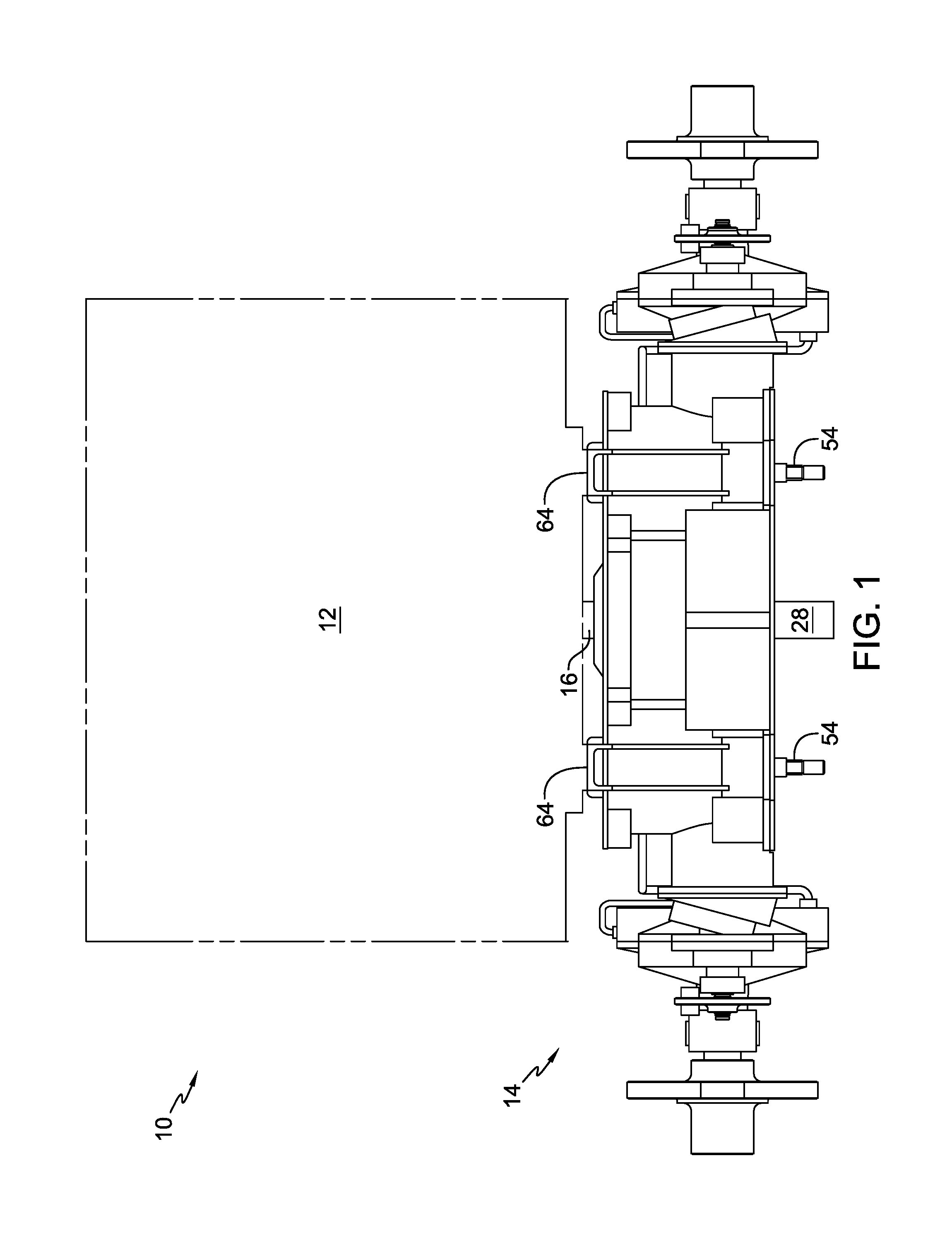
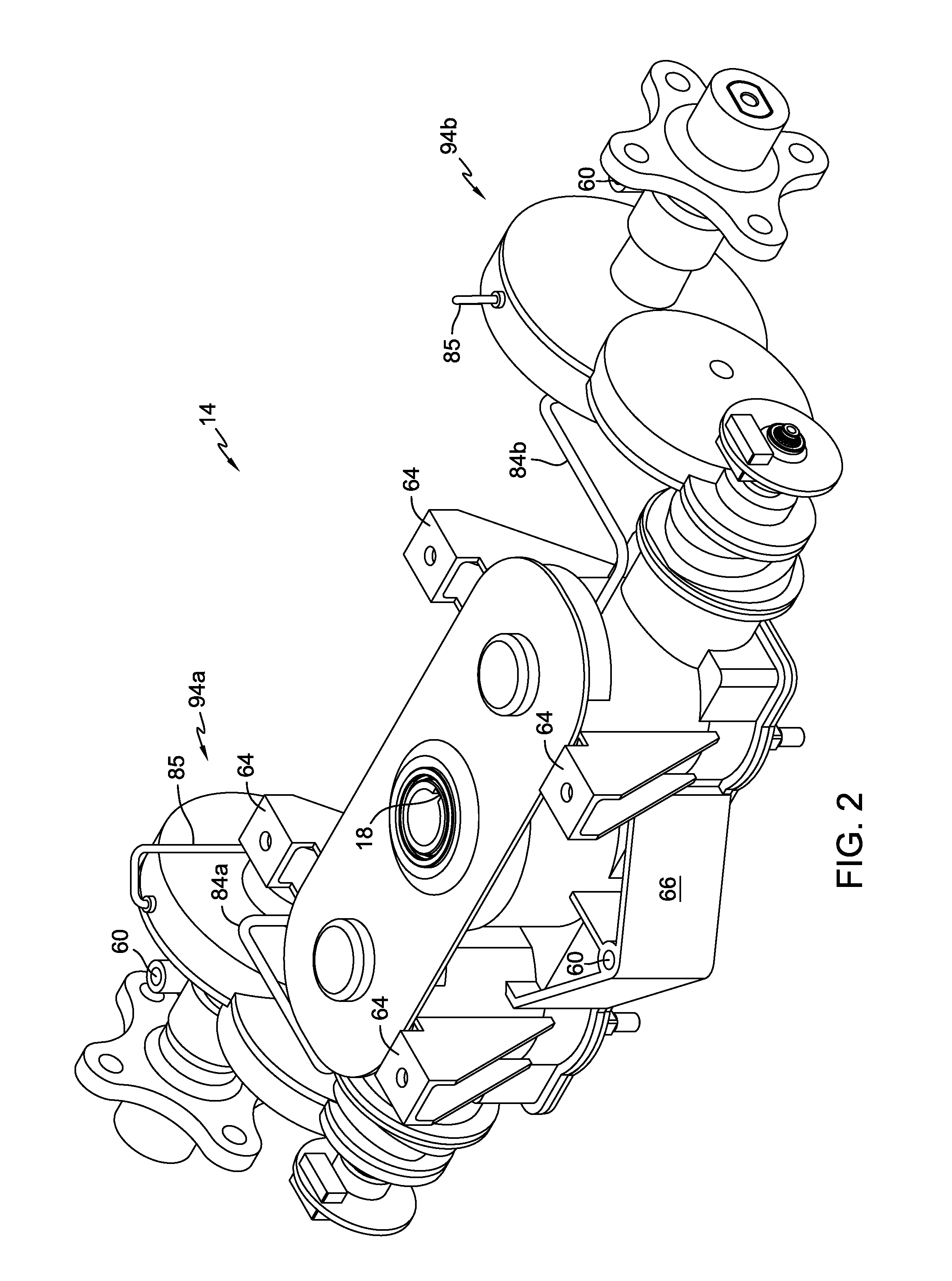
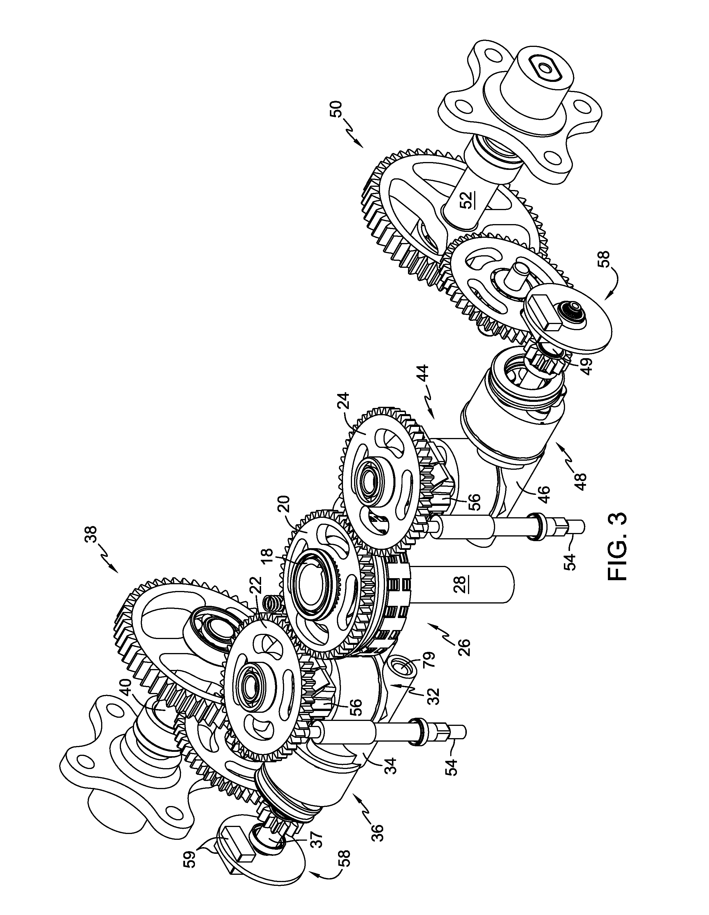
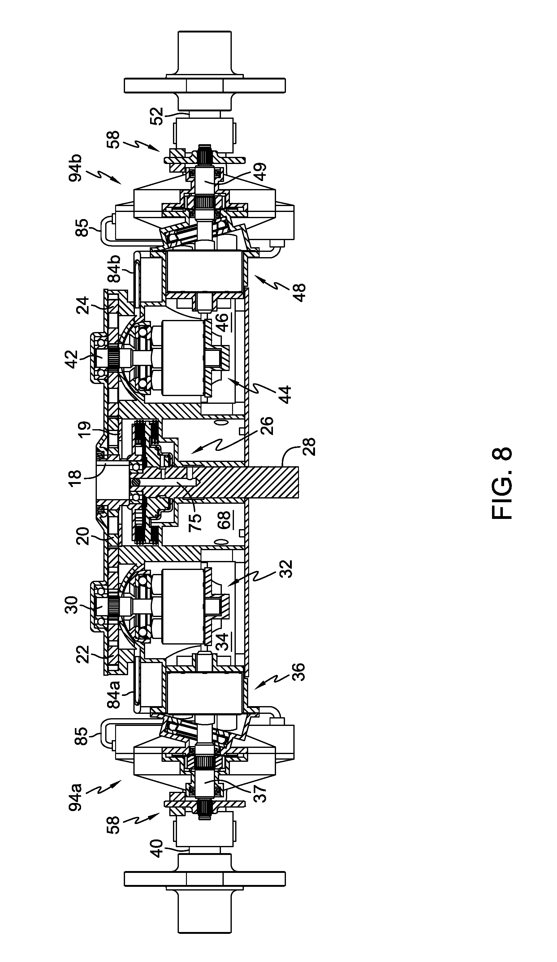
Turning now to the figures, there is illustrated in FIG. 1 an embodiment of the invention. Drive train assembly 10 comprises a prime mover in the form of engine 12, which is mounted on a transmission or transaxle assembly 14. Additional details of transaxle assembly 14 may be seen in FIGS. 2 and 3. Engine 12 has an output shaft 16 that engages input member 18 of transaxle assembly 14. As shown in FIG. 1, output shaft 16 drives input member 18 which in turn drives first gear 20. First gear 20 then drives second gear 22 and third gear 24. Input member 18 is also selectively engageable to power take off 26, as shown in FIG. 8 and as discussed in detail below. When power take off 26 is engaged, output shaft 16 is coupled to power take off shaft 28, which may then be used to drive an implement such as a mowing deck (not shown) or have a pulley mounted thereon for the purpose of connecting power take off shaft 28 by means of a belt to a driven device such as an auxiliary pump (not shown).
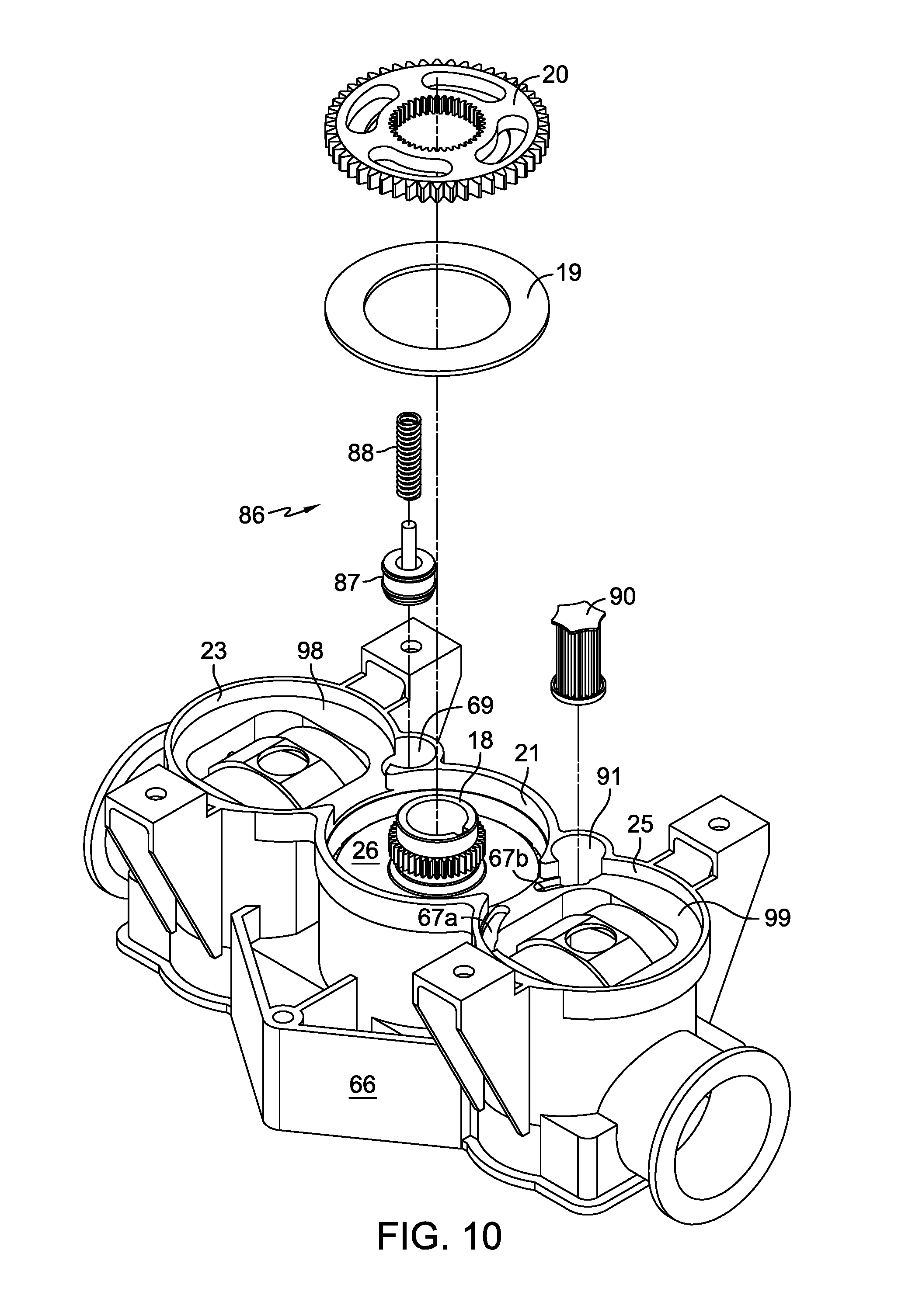
Power take off mechanisms, such as power take off 26, are well known in the art. Moreover, it will be appreciated by those in the art that any number of power take off mechanisms will be covered by the scope of the present invention. In the embodiment shown, output shaft 16 is coupled to input member 18. Input member 18 is the coupling rotor of power take off 26. Input member 18 is splined (or otherwise engaged), as shown in FIGS. 8 and 10, to first gear 20 so that output shaft 16 drives both power take off input member 18 and first gear 20.
A brake assembly 58 may be located on each of the motor output shafts 37 and 49. The disc-style brake assembly 58 shown is well known in the art and is not illustrated in detail. Additional elements that may house and actuate brake pads 59 are not shown but are well known in the art.
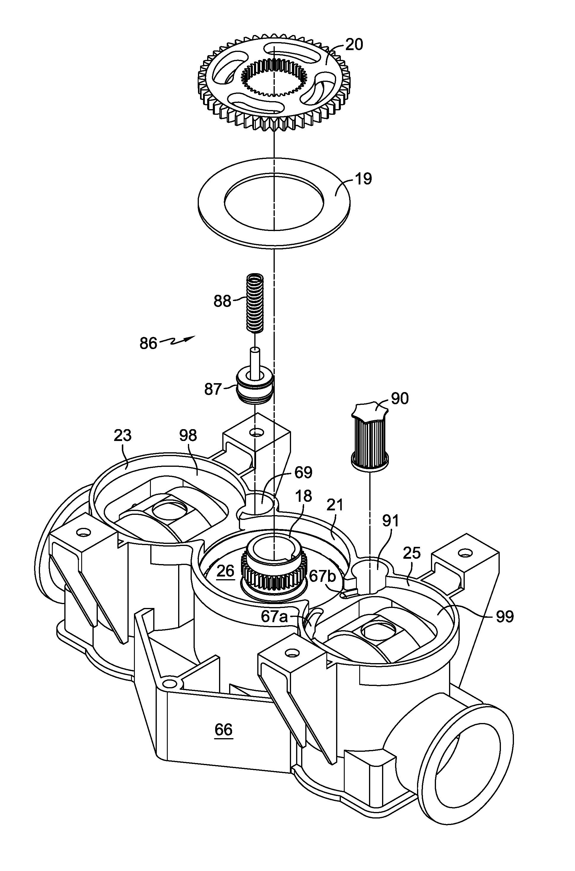
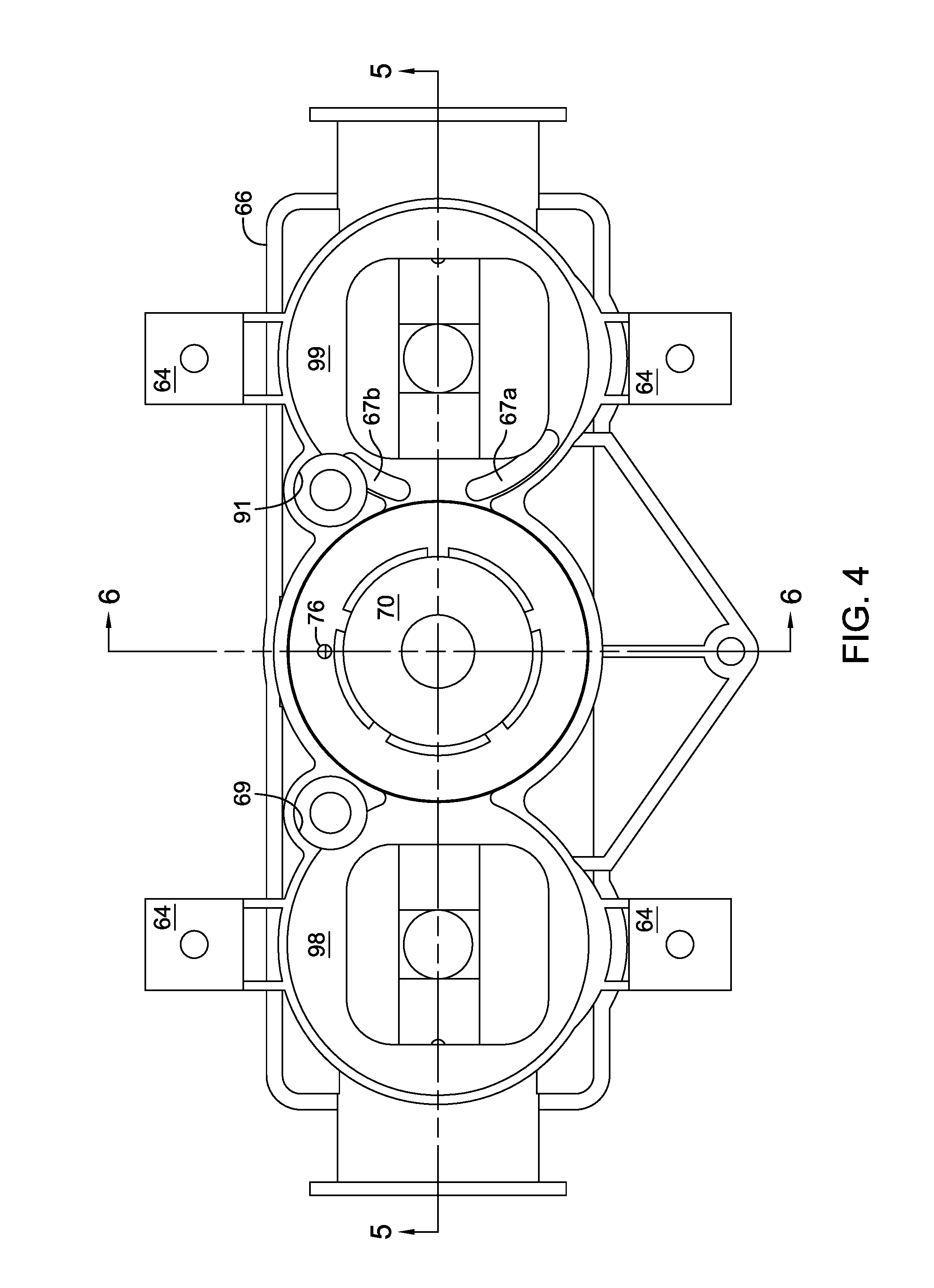
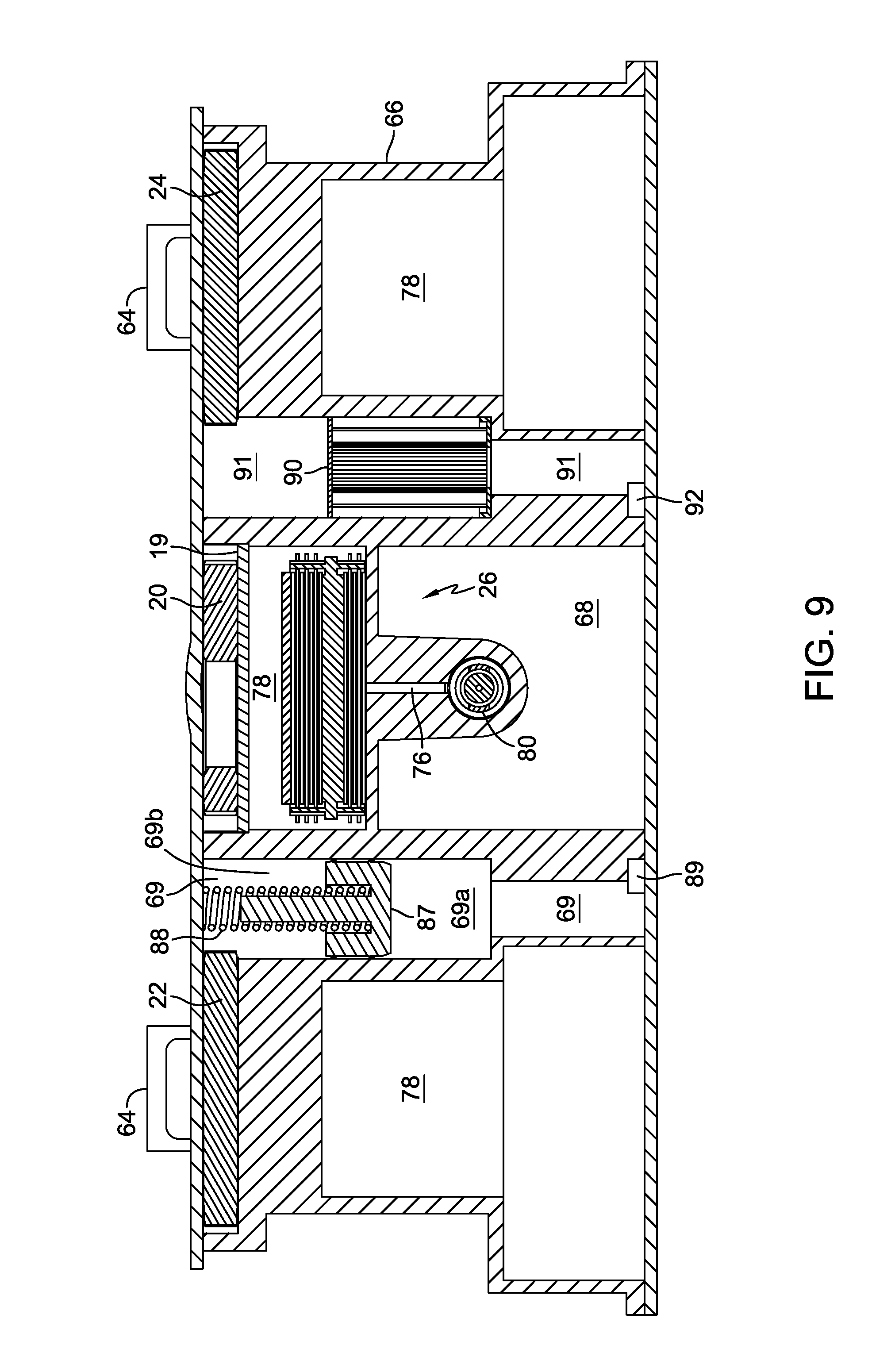
As shown in FIGS. 8, 9 and 10, first gear 20 rotates in gear chamber 21 on pressure plate 19, which is seated in central housing 66. Pressure plate 19 serves as a gear pump running surface for gear 20. Second gear 22 rotates in second gear chamber 23 on gear pump running surface 98 and third gear 24 rotates in third gear chamber 25 on gear pump running surface 99. In the embodiment shown, gear pump running surfaces 98 and 99 are integrally formed in housing 66. In an alternative embodiment (not shown) pressure plates similar to pressure plate 19 may be added to gear chambers 98 and 99 to prevent excessive wear to housing 66.
The configuration and operation of hydraulic pumps, motors, shafts and gearing such as that shown in FIGS. 3 and 8 is well known in the art and will only briefly be explained herein. Details of such hydraulic components can be found, for example, in U.S. Pat. No. 6,705,840, which is incorporated herein by reference in its entirety. Second gear 22 is coupled to a first pump shaft 30 that then drives first pump 32. First pump 32 may be mounted on a first center section 34, on which may be mounted a first motor 36. First motor 36 may then drive a first gear train 38 that then drives a first axle shaft 40. Axle shaft 40 may drive a vehicle tire (not shown) or other mechanism. First motor 36 may also directly drive axle shaft 40 rather than driving a gear train.
Third gear 24 is similarly coupled to second pump shaft 42 that then drives second pump 44. Second pump 44 may be mounted on a second center section 46, on which may be mounted a second motor 48. It will be understood that center sections 34 and 46 will include hydraulic porting (not shown) to connect the respective pumps and motors. Second motor 48 may then drive a second gear train 50 that then drives a second axle shaft 52. Second axle shaft 52 may drive a vehicle tire (not shown) or other mechanism. Second motor 48 may also directly drive second axle shaft 52 rather than driving a gear train.
In combination, gears 20 and 22 or gears 20 and 24 may form a gear pump that may be used to provide replenishment fluid to first pump 32 and first motor 36 and second pump 44 and second motor 48 as well as hydraulic pressure to actuate power take off 26. Generally, using input gears as gear pumps is generally known in the art, an example of which is disclosed in, for example, U.S. Pat. No. 7,225,617, which is incorporated herein by reference in its entirety.
Drive train assembly 10 and transaxle assembly 14 may further comprise actuator arms 54 to modify the position of swash plates 56, and thus the displacements of first pump 32 and second pump 44. First motor 36 and second motor 48 may also be adjustable in displacement.
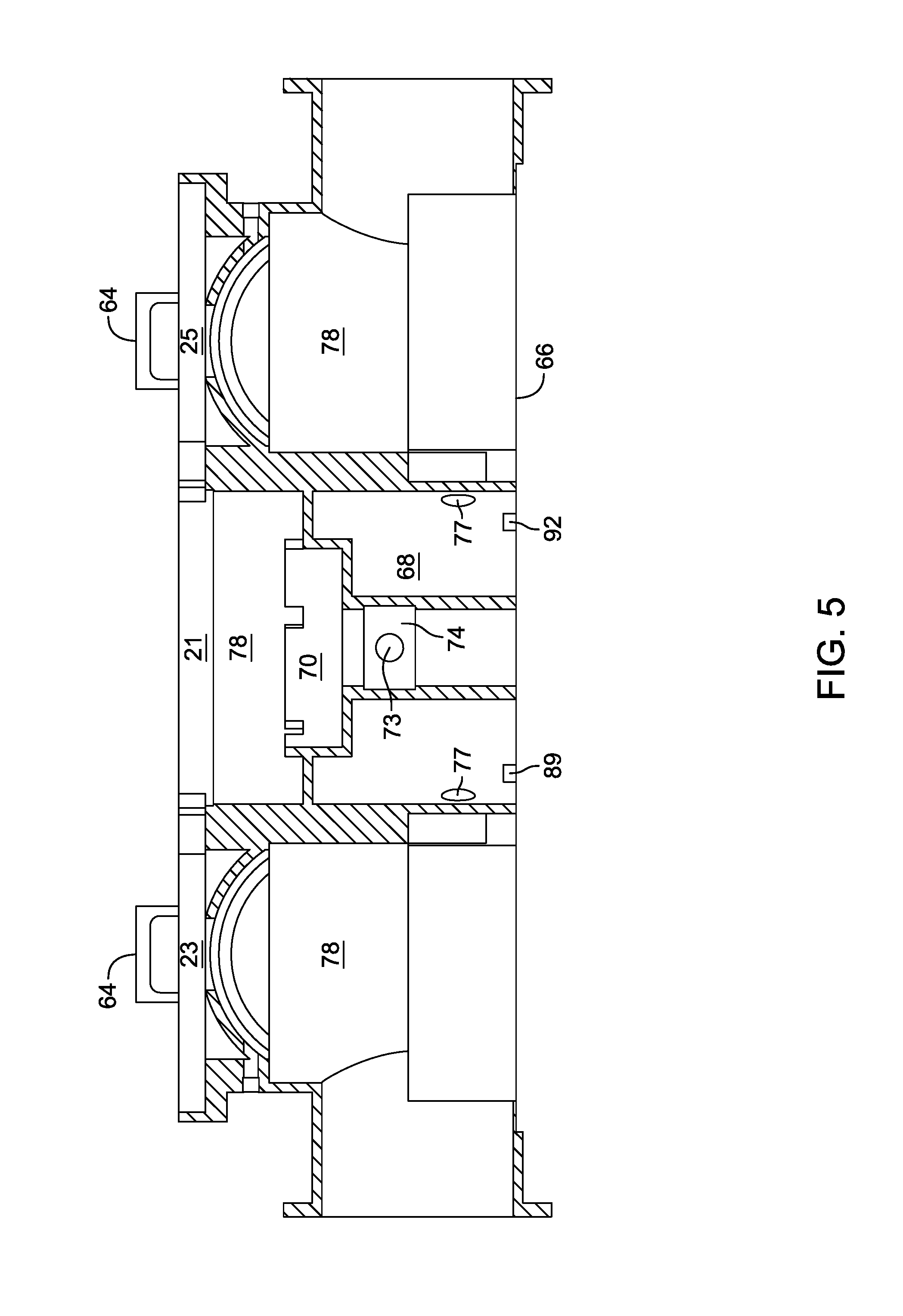
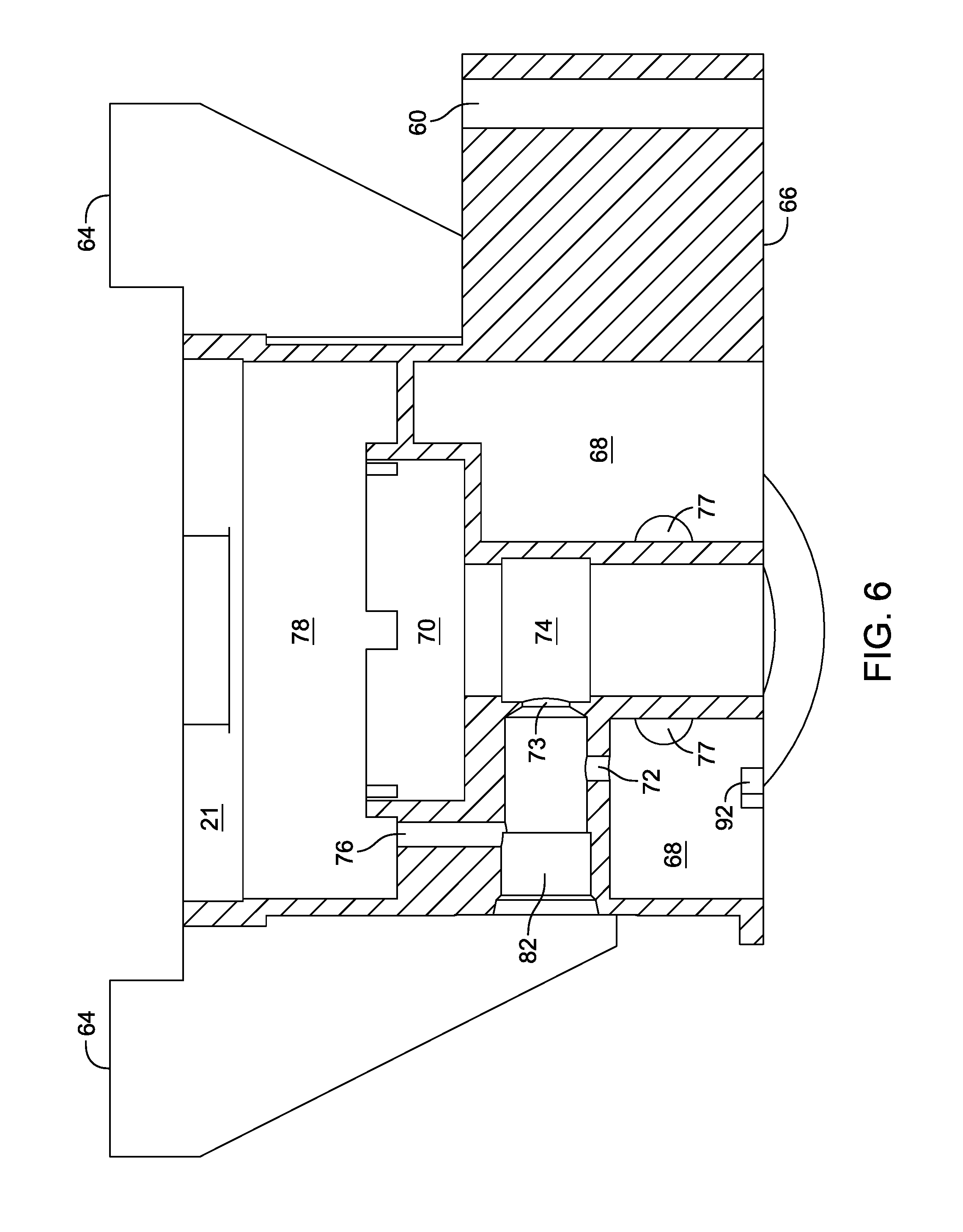
The housings of transaxle assembly 14 may provide multiple functions. By way of example, the housings may provide containment for the internal elements of transaxle assembly 14 previously described. As shown in FIGS. 2 and 7, the housings may also provide attachment points 60 to aid in attachment of drive train assembly 10 to a vehicle frame 62. Central housing 66 shown in, among others, FIGS. 2, 4, 5, 6 and 7, also provides engine support pads 64 for attachment of engine 12. Thus, attachment of engine 12 to transaxle assembly 14 creates drive train assembly 10 and allows an equipment manufacturer to simplify installation of the engine and transaxle assembly by forming a unitary assembly prior to installation in a vehicle. Three-point attachment of assembly 10 to frame 62 is illustrated in FIG. 7, but additional attachment points may be added to housing members of transaxle 14, if needed. This may be done to reduce and control stresses imparted to transaxle 14 when frame 62 flexes.
Central housing 66 may also provide locations for numerous elements of drive train assembly 10. For example, accumulator chamber 68 may be provided to help operate power take off 26 and to function as a charge fluid gallery to provide replenishment fluid to first center section 34 and second center section 46. Additionally, central housing 66 may comprise passages 77, which connect chamber 68 to center sections 34 and 46 as shown in FIGS. 5 and 6. There are two passages 77 connecting chamber 68 with each of the center sections 34 and 46. Check valves 79, located in center sections 34 and 46 between each passage 77 and pumps 32 and 34, may additionally be provided. Accumulators such as accumulator chamber 68 are well known in the art and will not be described in detail herein. Moreover, it will be appreciated by those of skill in the art that any number of accumulators will be covered by the scope of the present invention. As such, the elements of the accumulator chamber 68 will only be generally described.
In the depicted embodiment as shown in FIGS. 9 and 10, piston 87 interfaces with the wall of piston chamber 69 in central housing 66 such that it divides accumulator piston chamber 69 into a lower portion 69a and upper portion 69b. Pressurized fluid may flow into accumulator piston chamber 69 from accumulator chamber 68. The pressure in the lower portion of accumulator piston chamber 69 is equal to the pressure in the hydraulic circuit formed in drive transaxle assembly 14. Under normal operating conditions, the force from the fluid pressure is greater than the force provided by spring 88 and thus spring 88 is compressed. If for any reason, such as the engagement of power take off 26, there is a pressure drop across the transaxle assembly 14, the force in spring 88 will be greater than the force from the fluid pressure and piston 87 driven by spring 88 will descend into lower portion 69a of accumulator piston chamber 69, pushing the accumulated lower pressure fluid into chamber 68 through passage 89 thus repressurizing the hydraulic circuit in transaxle assembly 14 for a short period of time.
As shown in, e.g., FIG. 6, a pocket 70 may be provided in central housing 66 to locate a power take off clutch assembly and optional brake (not shown) of power take off 26. The brake which may be located in pocket 70 facilitates deceleration of power take off shaft 28 and then prevents shaft 28 from moving when the power take off 26 is in a non-actuated condition.
A valve 80 may also be provided in central housing 66 to control power take off 26. Valve 80 may be manually actuated or may be remotely hydraulically or electrically actuated. The details of such manual or remote actuation are not shown, but such manual and remotely actuated valves are well known in the art. Valve 80 may reside in a port 82 formed in central housing 66. Pressurized fluid flows from accumulator chamber 68 into valve 80 by way of opening 72. Valve 80 then directs pressurized fluid through opening 73 to annular region 74, which is accessible to internal passages 75 formed in power take off shaft 28.
Pressurized fluid in internal passages 75 may cause power take off 26 to be actuated. For example, pressurized fluid flowing from internal passages 75 may move a clutch piston, which in turn compresses clutch stators and clutch rotors, engaging a power take off clutch assembly and coupling input member 18 with power take off shaft 28. Similarly, valve 80 may release pressure by way of passage 76 to reservoir 78 to permit power take off 26 to be deactivated. Valve 80 may also provide a pathway to release pressure from any passageways associated with a brake or a power take off clutch assembly.
Additionally, fluid filter 90 may also be provided inside central housing 66 as shown in FIGS. 9 and 10. The details of fluid filter 90 are not shown because fluid filters are well known in the art. Those of ordinary skill in the art will also understand that fluid filter 90 may be located at a multitude of locations along the hydraulic circuit formed in central housing 66 which drives transaxle assembly 14. In the depicted embodiment, pump kidneys 67a and 67b are formed in running surface 99 of housing 66 to serve as fluid passages to provide pressurized fluid (resulting from the interface of gears 20 and 24) to filter chamber 91. Pressurized fluid flows through filter 90 into chamber 68 by way of passage 92.
Certain optional elements may be provided. For example, an expansion tank, expansion volume or expansion volumes may be present. An internal expansion volume may be formed when gear train housing elements 95a and 96a are assembled together to form gear train housing assembly 94a on one side of housing 66 and a separate volume may be formed when gear train housing elements 95b and 96b are assembled together to form gear train housing assembly 94b on the opposite side of housing 66.
Expansion tubes 84a and 84b as shown in FIGS. 2, 7 and 8 (or equivalent internal passages not shown) connect reservoir 78 of housing 66 with the fluid expansion volume in gear train housing assemblies 94a and 94b, respectively. Housing assemblies 94a and 94b include overflow tubes 85 in the event fluid expands to a volume greater than the expansion volume available in gear train housing assemblies 94a and 94b. Note that it may be possible to use only one of the housing assemblies 94a or 94b as an expansion volume and therefore, only one of the expansion tubes 84a or 84b may be needed, but both housing assemblies 94a and 94b may still require overflow tubes 85 or other known venting elements.
In order for gear train housing assemblies 94a and 94b to function as expansion tanks, they must be sealed from housing 66 so that the fluid volumes contained in housing assemblies 94a and 94b are separated from the housing 66 fluid volume in a manner which permits fluid transfer (discharge and siphoning) through each of tubes 84a and 84b. If they are not sealed from housing 66 in a manner that allows them to be used as internal fluid expansion compartments, then an external expansion tank may be required.
In an alternate embodiment (not shown), output shaft 16 of engine 12 may rotate in the opposite direction. In that case, the positions of filter 90 and accumulator piston assembly 86 may be switched due to the resultant switch between pressure sides related to forward and reverse of a vehicle. As shown, the configuration of chambers 69 and 91 may be equivalent to enable easy switching of these elements and therefore, flexibility in manufacturing. Note that pump kidneys 67a and 67b would be formed in running surface 98 instead of running surface 99 to accommodate opposite rotation of shaft 16.
While specific embodiments have been described in detail, it will be appreciated by those skilled in the art that various modification and alternatives to those details could be developed in light of the overall teachings of the disclosure. Accordingly, the particular arrangements disclosed are meant to be illustrative only and not limiting as to the scope of the invention which is to be given the full breadth of the appended claims and any equivalent thereof.
* * * * *
D00000
D00001
D00002
D00003
D00004
D00005
D00006
D00007
D00008
D00009
D00010
XML
uspto.report is an independent third-party trademark research tool that is not affiliated, endorsed, or sponsored by the United States Patent and Trademark Office (USPTO) or any other governmental organization. The information provided by uspto.report is based on publicly available data at the time of writing and is intended for informational purposes only.
While we strive to provide accurate and up-to-date information, we do not guarantee the accuracy, completeness, reliability, or suitability of the information displayed on this site. The use of this site is at your own risk. Any reliance you place on such information is therefore strictly at your own risk.
All official trademark data, including owner information, should be verified by visiting the official USPTO website at www.uspto.gov. This site is not intended to replace professional legal advice and should not be used as a substitute for consulting with a legal professional who is knowledgeable about trademark law.