Treatment fluid
Shalagina , et al.
U.S. patent number 10,221,350 [Application Number 15/304,079] was granted by the patent office on 2019-03-05 for treatment fluid. This patent grant is currently assigned to SCHLUMBERGER TECHNOLOGY CORPORATION. The grantee listed for this patent is SCHLUMBERGER TECHNOLOGY CORPORATION. Invention is credited to Diankui Fu, Anastasia Evgenyevna Shalagina.


View All Diagrams
| United States Patent | 10,221,350 |
| Shalagina , et al. | March 5, 2019 |
Treatment fluid
Abstract
Fibers are employed to improve proppant transport in low viscosity treatment fluids. The treatment fluids employ fibers to inhibit proppant settling without an unacceptable bridging tendency. The fibers are preferably crimped staple fibers having 1-10 crimps/cm of fiber length, a crimp angle between 45 and 160 degrees and a mean diameter between 8 and 40 microns.
| Inventors: | Shalagina; Anastasia Evgenyevna (Koltsovo, RU), Fu; Diankui (Kuala Lumpur, RU) | ||||||||||
|---|---|---|---|---|---|---|---|---|---|---|---|
| Applicant: |
|
||||||||||
| Assignee: | SCHLUMBERGER TECHNOLOGY
CORPORATION (Sugar Land, TX) |
||||||||||
| Family ID: | 54324353 | ||||||||||
| Appl. No.: | 15/304,079 | ||||||||||
| Filed: | April 15, 2014 | ||||||||||
| PCT Filed: | April 15, 2014 | ||||||||||
| PCT No.: | PCT/RU2014/000271 | ||||||||||
| 371(c)(1),(2),(4) Date: | October 14, 2016 | ||||||||||
| PCT Pub. No.: | WO2015/160275 | ||||||||||
| PCT Pub. Date: | October 22, 2015 |
Prior Publication Data
| Document Identifier | Publication Date | |
|---|---|---|
| US 20170037305 A1 | Feb 9, 2017 | |
| Current U.S. Class: | 1/1 |
| Current CPC Class: | E21B 43/267 (20130101); C09K 8/92 (20130101); C09K 8/80 (20130101); C09K 8/885 (20130101); E21B 43/26 (20130101); C09K 2208/28 (20130101); C09K 2208/08 (20130101) |
| Current International Class: | C09K 8/80 (20060101); C09K 8/92 (20060101); E21B 43/267 (20060101); C09K 8/88 (20060101); E21B 43/26 (20060101) |
References Cited [Referenced By]
U.S. Patent Documents
| 3850247 | November 1974 | Tinsley |
| 4406850 | September 1983 | Hills |
| 5082720 | January 1992 | Hayes |
| 5330005 | July 1994 | Roger et al. |
| 5501275 | March 1996 | Card et al. |
| 5518996 | May 1996 | Maroy et al. |
| 5618479 | April 1997 | Lijten et al. |
| 5905468 | May 1999 | Ikawa et al. |
| 6419019 | July 2002 | Palmer et al. |
| 7044220 | May 2006 | Nguyen et al. |
| 7250127 | July 2007 | Geck et al. |
| 7275596 | October 2007 | Willberg et al. |
| 7281581 | October 2007 | Nguyen et al. |
| 7325608 | February 2008 | Van Batenburg et al. |
| 7380601 | June 2008 | Willberg et al. |
| 7581590 | September 2009 | Lesko et al. |
| 7784541 | August 2010 | Hartman et al. |
| 7789146 | September 2010 | Panga et al. |
| 7833950 | November 2010 | Willberg et al. |
| 8008234 | August 2011 | Panga et al. |
| 8061424 | November 2011 | Willberg et al. |
| 8066068 | November 2011 | Lesko et al. |
| 8119574 | February 2012 | Panga et al. |
| 8167043 | May 2012 | Willberg et al. |
| 8210249 | July 2012 | Panga et al. |
| 8227026 | July 2012 | McDaniel et al. |
| 8230925 | July 2012 | Willberg et al. |
| 8234072 | July 2012 | Smith, Jr. et al. |
| 8372787 | February 2013 | Droger |
| 2002/0007169 | January 2002 | Graef |
| 2004/0228890 | November 2004 | Blin et al. |
| 2008/0006413 | January 2008 | Le Gloahec et al. |
| 2008/0070810 | March 2008 | Mang |
| 2008/0135242 | June 2008 | Lesko et al. |
| 2008/0196896 | August 2008 | Bustos et al. |
| 2008/0236832 | October 2008 | Fu et al. |
| 2010/0263870 | October 2010 | Willberg et al. |
| 2010/0272994 | October 2010 | Carlson et al. |
| 2010/0288495 | November 2010 | Willberg et al. |
| 2010/0288500 | November 2010 | Carlson et al. |
| 2010/0300688 | December 2010 | Panga et al. |
| 2011/0098202 | April 2011 | James et al. |
| 2011/0240293 | October 2011 | Lesko et al. |
| 2012/0000641 | January 2012 | Panga et al. |
| 2012/0048555 | March 2012 | Hughes et al. |
| 2012/0067581 | March 2012 | Auzerais et al. |
| 2012/0111563 | May 2012 | Abad et al. |
| 2012/0129737 | May 2012 | Lesko et al. |
| 2012/0132421 | May 2012 | Loiseau et al. |
| 2012/0138296 | June 2012 | Panga et al. |
| 2012/0305245 | December 2012 | Loiseau et al. |
| 2012/0305254 | December 2012 | Chen et al. |
| 2012/0325472 | December 2012 | Litvinets et al. |
| 2013/0048285 | February 2013 | Boulard et al. |
| 2013/0066617 | March 2013 | Weng |
| 2013/0134088 | May 2013 | Dahringer et al. |
| 2013/0233542 | September 2013 | Shampine et al. |
| 2015/0060063 | March 2015 | Miller |
| 2016/0215604 | July 2016 | Potapenko |
| 2017/0037305 | February 2017 | Shalagina et al. |
| 2017/0037306 | February 2017 | Shalagina et al. |
| 2309971 | Nov 2007 | RU | |||
| 2004005671 | Jan 2004 | WO | |||
| 2004037946 | May 2004 | WO | |||
| 2007086771 | Aug 2007 | WO | |||
| 2009005387 | Jan 2009 | WO | |||
| 2010075248 | Jul 2010 | WO | |||
| 2011050046 | Apr 2011 | WO | |||
| 2012054456 | Apr 2012 | WO | |||
| 2013085412 | Jun 2013 | WO | |||
| 2014039216 | Mar 2014 | WO | |||
Other References
|
Vasudevan et al., "Field Test of a Novel Low Viscosity Fracturing Fluid in the Lost Hills Fields, California", SPE 68854, SPE Western Regional Meeting, Bakersfield, California, Mar. 26-30, 2001, 11 pages. cited by applicant . Engels et al., "A Mechanical Methodology of Improved Proppant Transport in Low-Viscosity Fluids: Application of a Fiber-Assisted Transport Technique in East Texas", SPE 91434, 2004 SPE Eastern Regional Meeting, Charleston, West Virgina, Sep. 15-17, 2004, 11 pages. cited by applicant . International Search Report and Written Opinion issued in International Patent Application No. PCT/RU2014/000837 dated Mar. 5, 2015; 8 pages. cited by applicant . International Search Report issued in International Patent Application No. PCT/RU2014/000271 dated Jan. 22, 2015; 3 pages. cited by applicant . Hager et al., "A revolutionary product concept: Silicone gum pellets as additives for thermoplastics", Society of Plastics Engineers International Conference on Polyolefins 2005: The Challenges of Globalization, vol. 2, 2005, pp. 604-613. cited by applicant . Written Opinion issued in International Patent Application No. PCT/RU2014/000271 dated Jan. 22, 2015; 4 pages. cited by applicant . International Search Report and Written Opinion issued in International Patent Application No. PCT/RU2014/000838 dated Aug. 13, 2015; 7 pages. cited by applicant. |
Primary Examiner: Ahuja; Anuradha
Attorney, Agent or Firm: Tran; Andrea E.
Claims
We claim:
1. A treatment fluid, comprising: a carrier fluid having a viscosity lower than 50 mPa-s at a shear rate of 170 s.sup.-1 and a temperature of 25.degree. C.; proppant dispersed in the carrier fluid; and fibers dispersed in the carrier fluid the fibers being crimped staple fibers having 1 to 10 crimps/cm of fiber length, a crimp angle between 45 and 160 degrees and a mean diameter between 8 and 40 microns.
2. The treatment fluid of claim 1, wherein the carrier fluid is slickwater or brine.
3. The treatment fluid of claim 1, comprising from 0.06 to 1 kg/L of the proppant based on the total volume of the carrier fluid.
4. The treatment fluid of claim 1, wherein the fibers are dispersed in the carrier fluid in an amount effective to inhibit settling of the proppant in the carrier fluid.
5. The treatment fluid of claim 1, wherein the fibers are dispersed in the carrier fluid at a concentration that is insufficient to cause fiber bridging, wherein fiber bridging is defined as a condition whereby the fibers aggregate and form a plug that inhibits fluid flow through an orifice.
6. The treatment fluid of claim 1, wherein the fibers are dispersed in the carrier fluid at a concentration that is effective to inhibit settling of the proppant and that is insufficient to cause fiber bridging, wherein fiber briding is defined as a condition whereby the fibers aggregate and form a plug that inhibits fluid flow through an orifice.
7. The treatment fluid of claim 1, wherein the fibers are dispersed in the carrier fluid at a concentration that is effective to inhibit settling of the proppant and that is insufficient to cause fiber bridging during a small slot test comprising passing the treatment fluid comprising the carrier fluid and the fibers without proppant at 25.degree. C. through a bridging apparatus comprising a 1.8 mm slot that is about 15 to 16 mm wide and 65 mm long at a flow rate equal to 15 cm/s, wherein fiber bridging is defined as a condition whereby the fibers aggregate and form a plug that inhibits fluid flow through the slot.
8. The treatment fluid of claim 1, wherein an effective concentration of the fibers to inhibit settling of the proppant is determined by comparing proppant accumulation in a narrow fracture flow test comprising pumping the treatment fluid at 25.degree. C. through a 2 mm slot measuring 3 m long by 0.5 m high for 60 seconds at a flow velocity of 65 cm/s, relative to a reference fluid containing the carrier fluid and proppant only without the fibers.
9. The treatment fluid of claim 1, comprising from 1.2 to 12 g/L of the fibers based on the total volume of the carrier fluid.
10. The treatment fluid of claim 1, comprising less than 4.8 g/L of the fibers based on the total volume of the carrier fluid.
11. The treatment fluid of claim 1, wherein the fibers further comprise polyester.
12. The treatment fluid of claim 1, wherein the fibers further comprise polyester that undergoes hydrolysis at a temperature lower than 93.degree. C., wherein the hydrolysis comprises heating 10 g of the fibers in 1 L deionized water until the deionized water has a pH lower than 3.
13. The treatment fluid of claim 1, wherein the fibers further comprise polyester that undergoes hydrolysis at a temperature between 93.degree. C. and 149.degree. C., wherein the hydrolysis comprises heating 10 g of the fibers in 1 L deionized water until the deionized water has a pH lower than 3.
14. The treatment fluid of claim 1, wherein the fibers are selected from the group consisting of polylactic acid, polyglycolic acid, copolymers of polylactic acid and polyglycolic acid, polyethylene terephthalate, polyester, polyamide, polycaprolactam and polylactone, poly(butylene) succinate, polydioxanone, glass, ceramics, carbon-based compounds, elements in metallic form, metal alloys, wool, basalt, acrylic, polyethylene, polypropylene, novoloid resin, polyphenylene sulfide, polyvinyl chloride, polyvinylidene chloride, polyurethane, polyvinyl alcohol, polybenzimidazole, polyhydroquinone-diimidazopyridine, poly(p-phenylene-2,6- benzobisoxazole), rayon, cotton, cellulose, rubber, and combinations thereof.
15. The treatment fluid of claim 1, further comprising a friction reducer.
16. A method to treat a subterranean formation penetrated by a wellbore, comprising: injecting a treatment fluid into the subterranean formation to form a hydraulic fracture system, wherein the treatment fluid comprises: a carrier fluid having a viscosity lower than 50 mPa-s at a shear rate of 170 s.sup.-1 and a temperature of 25.degree. C.; proppant dispersed in the carrier fluid; and crimped staple fibers dispersed in the carrier fluid, the fibers having 1 to 10 crimps/cm of fiber length, a crimp angle between 45 and 160 degrees and a mean diameter between 8 and 40 microns; and maintaining a rate of the injection of the treatment fluid to avoid bridging in the wellbore.
17. The method of claim 16, further comprising injecting a pre-pad, pad, tail or flush stage or a combination thereof.
18. The method of claim 16, wherein the treatment fluid comprises from 0.06 to 1 kg L of the proppant based on the total volume of the carrier fluid.
19. The method of claim 16, wherein the treatment fluid comprises less than 4.8 g L of the fibers based on the total volume of the carrier fluid.
20. The method of claim 16, wherein the fibers further comprise polyester and further comprising hydrolyzing the fibers downhole after the injection.
21. The method of claim 16, wherein the fibers are present in the treatment fluid in an amount effective to inhibit settling of the proppant, wherein proppant settling is measured by comparing proppant accumulation in a narrow fracture flow test comprising pumping the treatment fluid at 25.degree. C. through a 2 mm slot measuring 3 m long by 0.5 m high for 60 seconds at a flow velocity of 65 cm/s, relative to a fiber-free reference fluid containing only the carrier fluid and the proppant.
22. A method to inhibit proppant settling in a treatment fluid circulated in a wellbore, the treatment fluid comprising the proppant dispersed in a carrier fluid having a viscosity lower than 50 mPa-s at a shear rate of 170 s.sup.-1 and a temperature of 25.degree. C., comprising: dispersing crimped staple fibers in the carrier fluid in an amount effective to inhibit proppant settling, the fibers having 1 to 10 crimps/cm of fiber length, a crimp angle between 45 and 160 degrees and a mean diameter between 8 and 40 microns; and maintaining a circulation rate to avoid bridging in the wellbore.
23. The method of claim 22, wherein the treatment fluid further comprises a friction reducer.
24. A system to treat a subterranean formation, comprising: a subterranean formation penetrated by a wellbore; a treatment fluid injection unit to supply a treatment fluid stage, comprising proppant in a carrier fluid having a viscosity lower than 50 mPa-s at a shear rate of 170 s.sup.-1 and a temperature of 25.degree. C., to the formation above a fracturing pressure to form a fracture system; and a fiber supply unit to introduce fibers into the treatment fluid, the fibers being crimpled staple fibers having 1 to 10 crimps/cm of fiber length, a crimp angle between 45 and 160 degrees and a mean diameter between 8 and 40 microns.
25. The system of claim 24, wherein the introduction of the fibers into the treatment fluid is in an amount suitable to inhibit proppant settling, and wherein the supply of the treatment fluid stage to the formation is at a flow rate sufficient to avoid inducing bridging.
Description
RELATED APPLICATIONS
This application is a 371 National Phase Application of International Patent Application No. PCT/RU2014/000271, filed Apr. 15, 2014. The disclosure of the priority application is hereby incorporated by reference herein in its entirety.
BACKGROUND
The statements in this section merely provide background information related to the present disclosure and may not constitute prior art.
Fibers have been used in some hydraulic fracturing treatments where a viscosified treatment fluid is used to carry proppant and/or where bridging contributed to by the fiber is desirable, e.g., in diversion applications. However, with low viscosity fluids such as, for example, treatments using slickwater (also sometimes referred to as waterfrac) to fracture shale or tight gas formations, bridging may be undesirable and narrow fracture widths would further exacerbate the bridging tendencies of fiber. Accordingly, there is a demand for further improvements in this area of technology.
SUMMARY
In some embodiments according to the disclosure herein, methods and systems using fibers are employed in low viscosity treatment fluids to inhibit proppant settling while obtaining suitable resistance to bridging, e.g., without bridging in some embodiments.
In some embodiments, a well treatment fluid may comprise a low viscosity carrier fluid, e.g., having a viscosity less than 50 mPa-s at a shear rate of 170 s.sup.-1 and a temperature of 25.degree. C., proppant dispersed in the carrier fluid, and fiber dispersed in the carrier fluid. Such fiber may be present in some embodiments in an amount effective to inhibit settling of the proppant, for example, in a static proppant settling test or in a large slot flow test without bridging at a flow rates equal to and greater than 10 cm/s.
In some embodiments, a method to treat a subterranean formation penetrated by a wellbore may comprise injecting a treatment fluid into the subterranean formation to form a hydraulic fracture system, the treatment fluid comprises: a low viscosity carrier fluid, proppant dispersed in the carrier fluid, and fiber dispersed in the carrier fluid. Such fiber may be present in an amount effective to inhibit settling of the proppant; and the method may include maintaining a rate of the injection to avoid bridging in the wellbore.
In some embodiments, a method to inhibit proppant settling in a low viscosity treatment fluid circulated in a wellbore may comprise dispersing fiber in the carrier fluid in an amount effective to inhibit settling of the proppant, and maintaining a rate of the circulation to avoid bridging in the wellbore.
In some embodiments, a system to treat a subterranean formation may comprise a subterranean formation penetrated by a wellbore; a treatment fluid injection unit to supply a treatment fluid stage, which comprises proppant in a low viscosity carrier fluid, to the formation above a fracturing pressure to form a fracture system; and a fiber supply unit to introduce fiber into the treatment fluid. In embodiments, the fiber is introduced into the treatment fluid in an amount suitable to inhibit proppant settling and/or the supply of the treatment fluid stage to the formation is at a flow rate sufficient to avoid inducing bridging.
BRIEF DESCRIPTION OF THE DRAWINGS
These and other features and advantages will be better understood by reference to the following detailed description when considered in conjunction with the accompanying drawings.
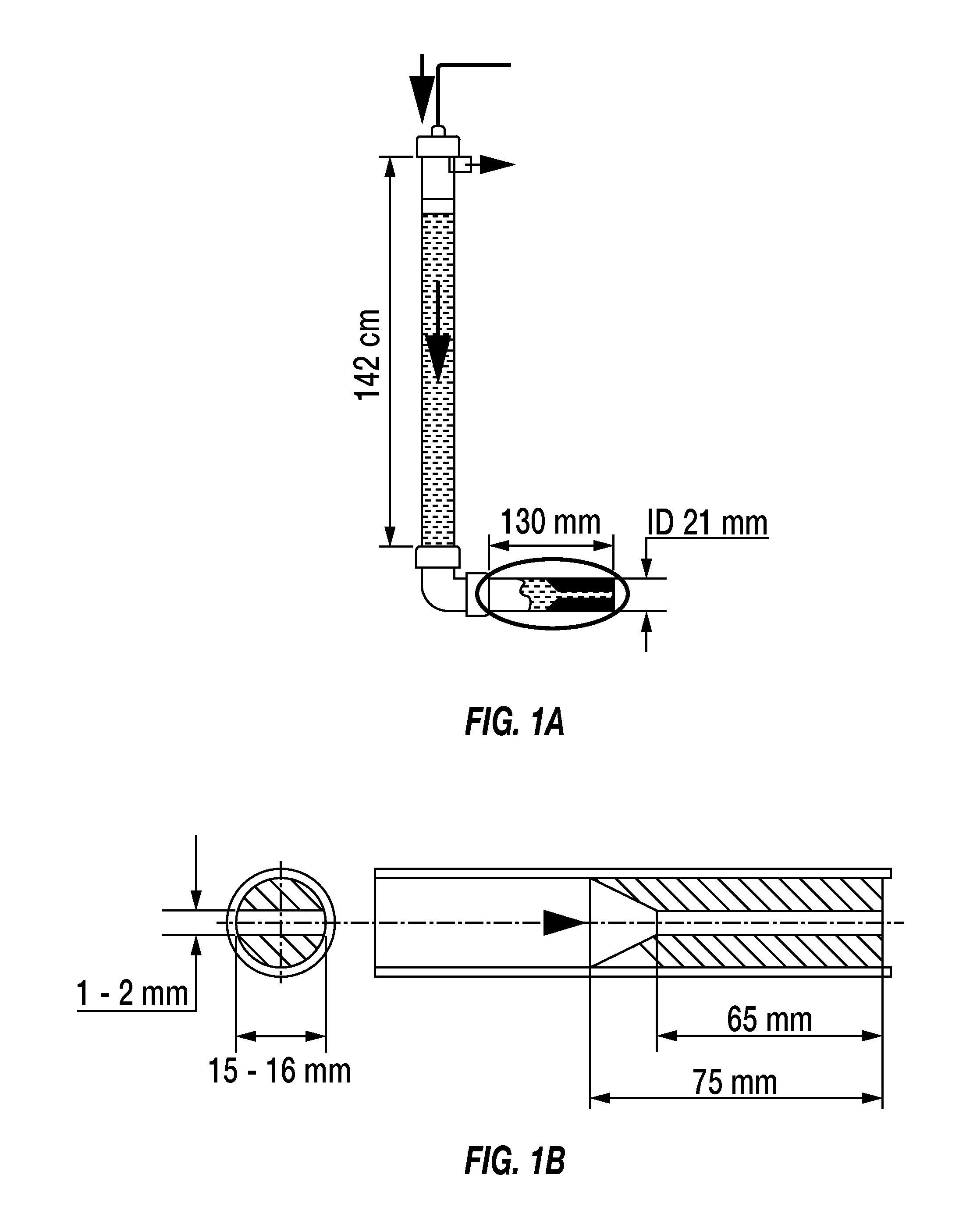
FIG. 1A schematically illustrates a bridging test apparatus according to embodiments.
FIG. 1B schematically illustrates an enlarged detail of the slot design in the apparatus of FIG. 1A.
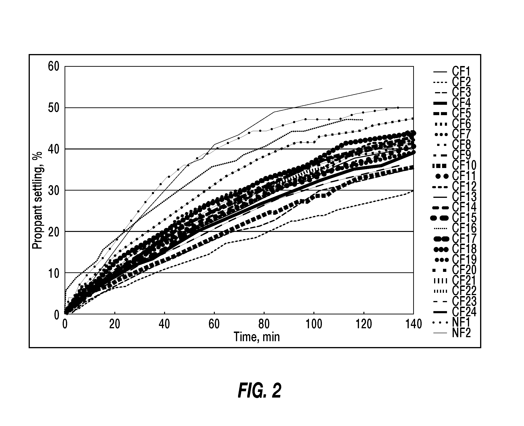
FIG. 2 schematically graphs the proppant settling in a treatment fluid with various fibers.
FIG. 3 schematically graphs the effect of fiber loading on proppant settling in a treatment fluid with crimped mid temperature fibers.
FIG. 4 schematically graphs the effect of fiber loading on proppant settling in a treatment fluid with crimped low temperature fibers.
FIG. 5 schematically graphs the effect of fiber diameter on proppant settling in a treatment fluid with crimped mid temperature fibers.
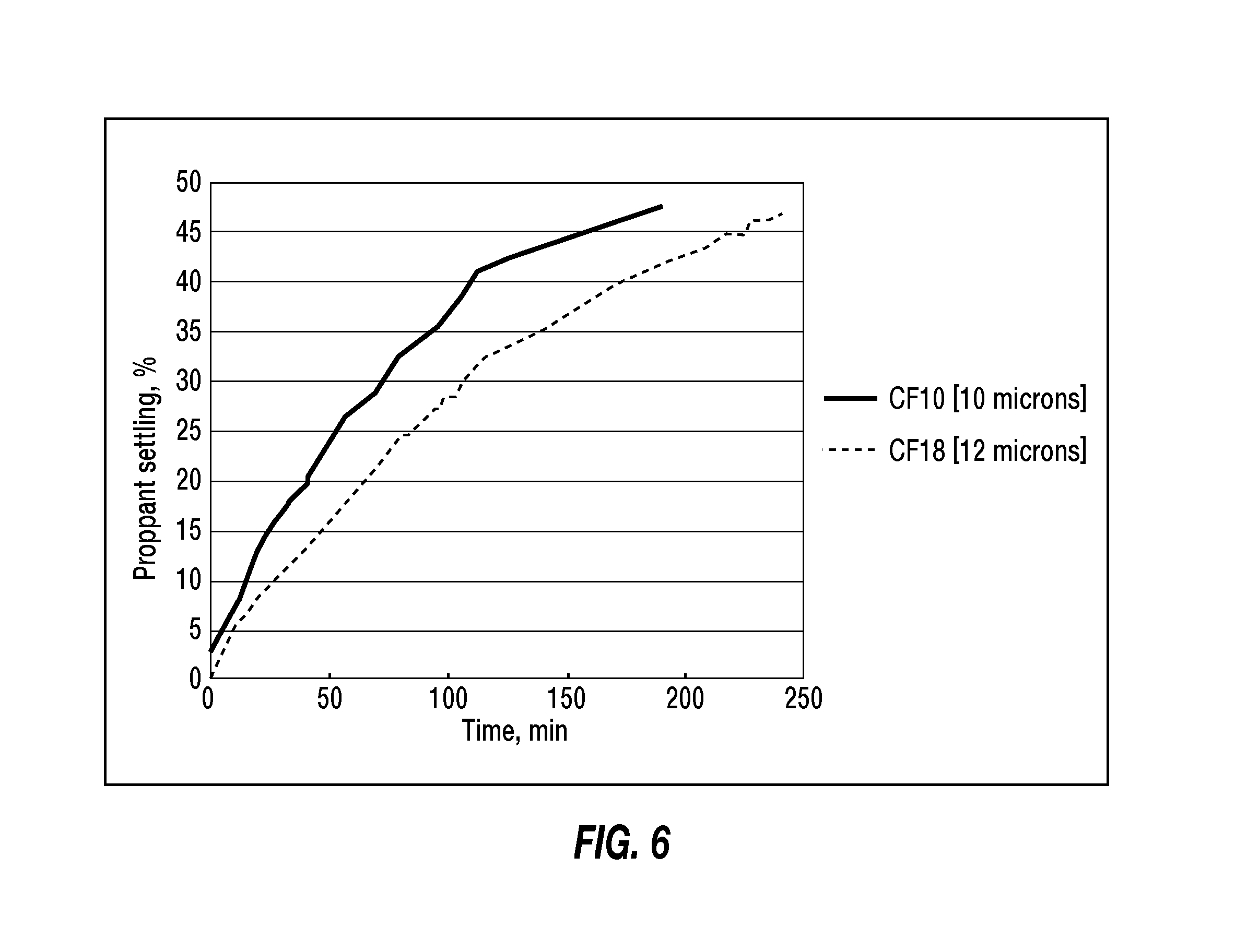
FIG. 6 schematically graphs the effect of fiber diameter on proppant settling in a treatment fluid with crimped low temperature fibers.
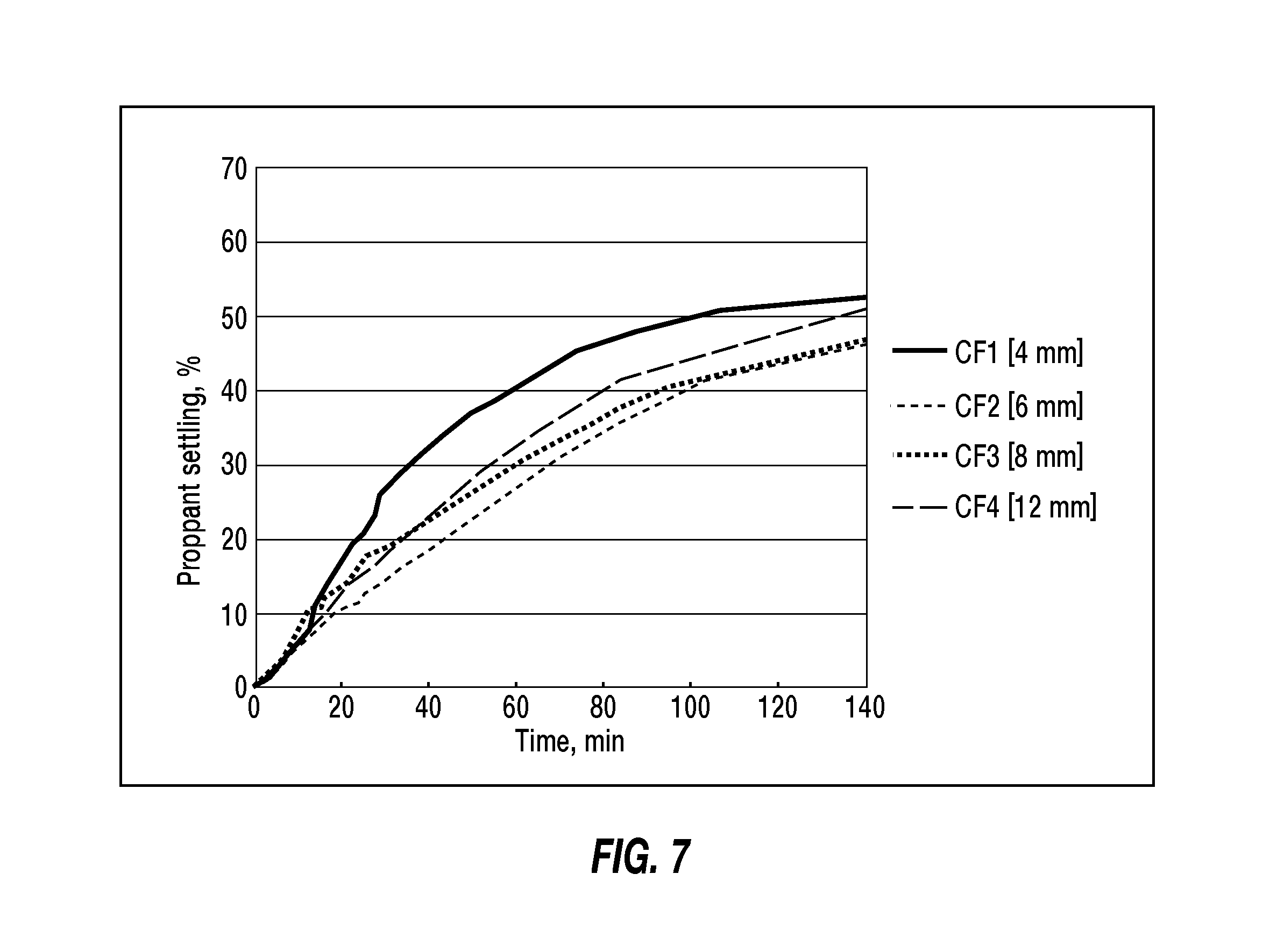
FIG. 7 schematically graphs the effect of fiber length on proppant settling in a treatment fluid with crimped mid temperature fibers.
FIG. 8 schematically graphs the effect of fiber length on proppant settling in a treatment fluid with crimped low temperature fibers.
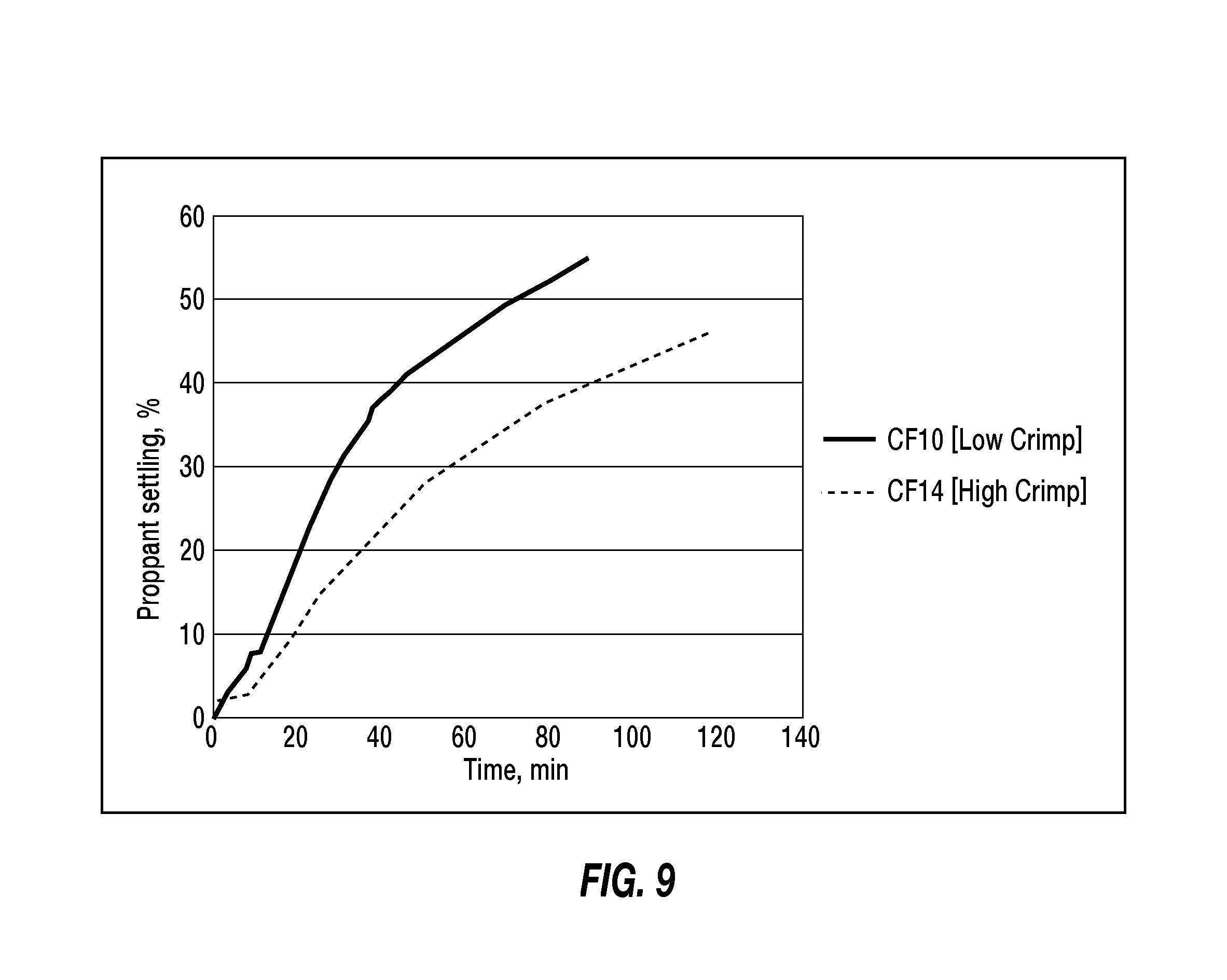
FIG. 9 schematically graphs the effect of crimp level on proppant settling in a treatment fluid with crimped low temperature fibers.
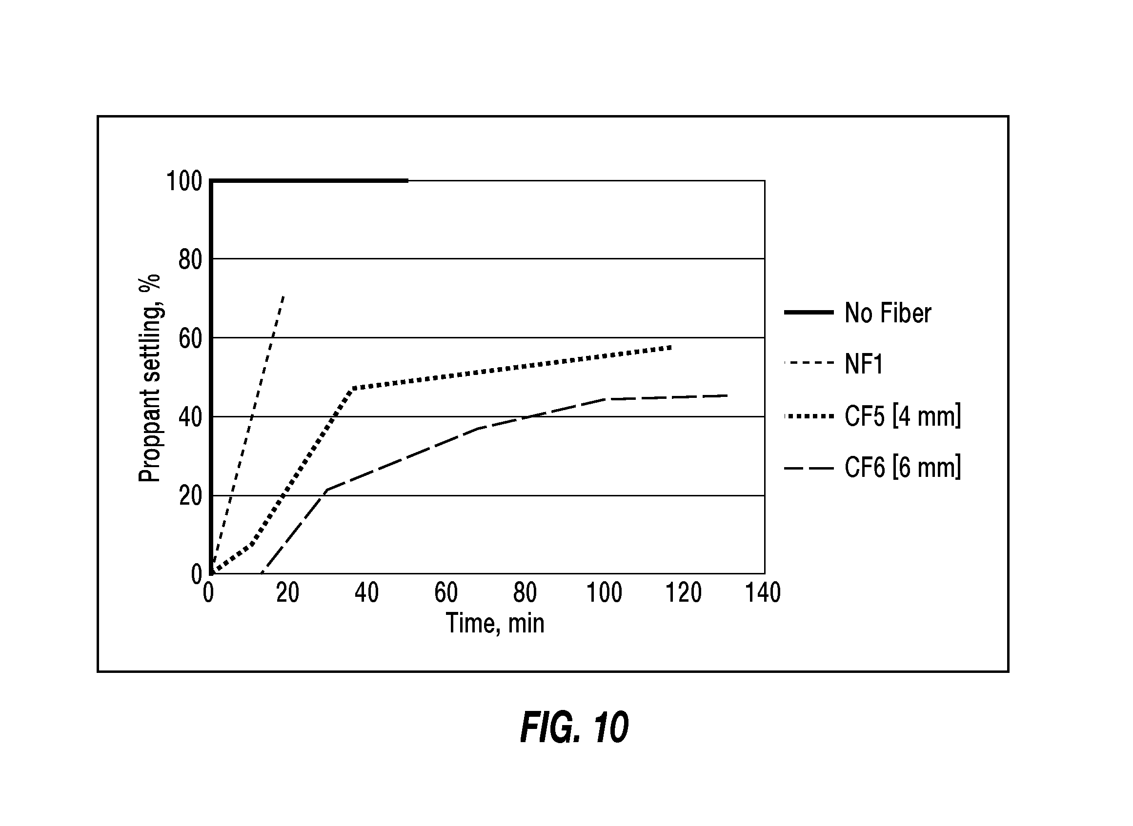
FIG. 10 schematically graphs the proppant settling in a slickwater fluid with various fibers.
DETAILED DESCRIPTION
For the purposes of promoting an understanding of the principles of the disclosure, reference will now be made to some illustrative embodiments of the current application. Like reference numerals used herein refer to like parts in the various drawings. Reference numerals without suffixed letters refer to the part(s) in general; reference numerals with suffixed letters refer to a specific one of the parts.
As used herein, "embodiments" refers to non-limiting examples of the application disclosed herein, whether claimed or not, which may be employed or present alone or in any combination or permutation with one or more other embodiments. Each embodiment disclosed herein should be regarded both as an added feature to be used with one or more other embodiments, as well as an alternative to be used separately or in lieu of one or more other embodiments. It should be understood that no limitation of the scope of the claimed subject matter is thereby intended, any alterations and further modifications in the illustrated embodiments, and any further applications of the principles of the application as illustrated therein as would normally occur to one skilled in the art to which the disclosure relates are contemplated herein.
Moreover, the schematic illustrations and descriptions provided herein are understood to be examples only, and components and operations may be combined or divided, and added or removed, as well as re-ordered in whole or part, unless stated explicitly to the contrary herein. Certain operations illustrated may be implemented by a computer executing a computer program product on a computer readable medium, where the computer program product comprises instructions causing the computer to execute one or more of the operations, or to issue commands to other devices to execute one or more of the operations.
It should be understood that, although a substantial portion of the following detailed description may be provided in the context of oilfield fracturing operations, other oilfield operations such as cementing, gravel packing, etc., or even non-oilfield well treatment operations, can utilize and benefit as well from the instant disclosure.
In some embodiments, a treatment fluid comprises a low viscosity carrier fluid having a low viscosity, proppant dispersed in the carrier fluid, and fiber dispersed in the carrier fluid. As used herein, a "low viscosity" fluid refers to one having a viscosity less than 50 mPa-s at a shear rate of 170 s.sup.-1 and a temperature of 25.degree. C. In some embodiments, the treatment fluid comprises proppant particles and fibers dispersed in a carrier fluid.
In some embodiments, the treatment fluid comprises from 0.01 to 1 kg/L of the proppant based on the total volume of the carrier fluid (from 0.1 to 8.3 ppa, pounds proppant added per gallon of carrier fluid), e.g., from 0.048 to 0.6 kg/L of the proppant based on the total volume of the carrier fluid (0.4 to 5 ppa), or from 0.12 to 0.48 kg/L of the proppant based on the total volume of the carrier fluid (from 1 to 4 ppa). As used herein, proppant loading is specified in weight of proppant added per volume of carrier fluid, e.g., kg/L (ppa=pounds of proppant added per gallon of carrier fluid). Exemplary proppants include ceramic proppant, sand, bauxite, glass beads, crushed nuts shells, polymeric proppant, rod shaped, and mixtures thereof.
In some embodiments, the fiber is dispersed in the carrier fluid in an amount effective to inhibit settling of the proppant. This settling inhibition may be evidenced, in some embodiments, for example, in a static proppant settling test at 25.degree. C. for 90 minutes. The proppant settling test in some embodiments involves placing the fluid in a container such as a graduated cylinder and recording the upper level of dispersed proppant in the fluid. The upper level of dispersed proppant is recorded at periodic time intervals while maintaining settling conditions. The proppant settling fraction is calculated as:
.times..times..times..times..times..times..times..times..times..times..ti- mes..times..times..times..times..times..times..times..times..times..times.- .times..times..times..times..times..times..times..times..times..infin. ##EQU00001##
The fiber inhibits proppant settling if the proppant settling fraction for the fluid containing the proppant and fiber has a lower proppant settling fraction than the same fluid without the fiber and with proppant only. In some embodiments, the proppant settling fraction of the treatment fluid in the static proppant settling test after 90 minutes is less than 50%, e.g., less than 40%.
In some embodiments, the fiber is dispersed in the carrier fluid in an amount insufficient to cause bridging, e.g., as determined in a small slot test comprising passing the treatment fluid comprising the carrier fluid and the fiber without proppant at 25.degree. C. through a bridging apparatus such as that shown in FIGS. 1A and 1B comprising a 1.0-1.8 mm slot that is 15-16 mm wide and 65 mm long at a flow rate equal to 15 cm/s, or at a flow rate equal to 10 cm/s.
In some embodiments the fiber is dispersed in the carrier fluid in both an amount effective to inhibit settling of the proppant and in an amount insufficient to cause bridging, wherein settling and bridging are determined by comparing proppant accumulation in a narrow fracture flow test comprising pumping the treatment fluid at 25.degree. C. through a 2 mm slot measuring 3 m long by 0.5 m high for 60 seconds at a flow velocity of 65 cm/s, or at a flow velocity of 20 cm/s, relative to a reference fluid containing the carrier fluid and proppant only without the fiber. In the narrow fracture flow test, the slot may be formed of flow cells with transparent windows to observe proppant settling at the bottom of the cells. Proppant settling is inhibited if testing of the fluid with the proppant and fiber results in measurably less proppant settling than the same fluid and proppant mixture without the fiber at the same testing conditions. Bridging is likewise observed in the narrow fracture flow test as regions exhibiting a reduction of fluid flow also resulting in proppant accumulation in the flow cells.
In some embodiments, the treatment fluid comprises from 1.2 to 12 g/L of the fibers based on the total volume of the carrier fluid (from 10 to 100 ppt, pounds per thousand gallons of carrier fluid), e.g., less than 4.8 g/L of the fibers based on the total volume of the carrier fluid (less than 40 ppt) or from 1.2 or 2.4 to 4.8 g/L of the fibers based on the total volume of the carrier fluid (from 10 or 20 to 40 ppt).
In some embodiments, the fibers are crimped staple fibers. In some embodiments, the crimped fibers comprise from 1 to 10 crimps/cm of length, a crimp angle from 45 to 160 degrees, an average extended length of fiber of from 4 to 15 mm, and/or a mean diameter of from 8 to 40 microns, or 8 to 12, or 8 to 10, or a combination thereof. In some embodiments, the fibers comprise low crimping equal to or less than 5 crimps/cm of fiber length, e.g., 1-5 crimps/cm.
Depending on the temperature that the treatment fluid will encounter, especially at downhole conditions, the fibers may be chosen depending on their resistance or degradability at the envisaged temperature. In the present disclosure, the terms "low temperature fibers", "mid temperature fibers" and "high temperature fibers" may be used to indicate the temperatures at which the fibers may be used for delayed degradation, e.g., by hydrolysis, at downhole conditions. Low temperatures are typically within the range of from about 60.degree. C. (140.degree. F.) to about 93.degree. C. (200.degree. F.); mid temperatures typically from about 94.degree. C. (201.degree. F.) to about 149.degree. C. (300.degree. F.); and high temperatures typically about 149.5.degree. C. (301.degree. F.) and above, or from about 149.5.degree. C. (301.degree. F.) to about 204.degree. C. (400.degree. F.).
In some embodiments, the fibers comprise polyester. In some embodiments, the polyester undergoes hydrolysis at a low temperature of less than about 93.degree. C. as determined by slowly heating 10 g of the fibers in 1 L deionized water until the pH of the water is less than 3, and in some embodiments, the polyester undergoes hydrolysis at a moderate temperature of between about 93.degree. C. and 149.degree. C. as determined by slowly heating 10 g of the fibers in 1 L deionized water until the pH of the water is less than 3, and in some embodiments, the polyester undergoes hydrolysis at a high temperature greater than 149.degree. C., e.g., between about 149.5.degree. C. and 204.degree. C. In some embodiments, the polyester is selected from the group consisting of polylactic acid, polyglycolic acid, copolymers of lactic and glycolic acid, and combinations thereof.
In some embodiments, the fiber is selected from the group consisting of polylactic acid (PLA), polyglycolic acid (PGA), polyethylene terephthalate (PET), polyester, polyamide, polycaprolactam and polylactone, poly(butylene) succinate, polydioxanone, nylon, glass, ceramics, carbon (including carbon-based compounds), elements in metallic form, metal alloys, wool, basalt, acrylic, polyethylene, polypropylene, novoloid resin, polyphenylene sulfide, polyvinyl chloride, polyvinylidene chloride, polyurethane, polyvinyl alcohol, polybenzimidazole, polyhydroquinone-diimidazopyridine, poly(p-phenylene-2,6-benzobisoxazole), rayon, cotton, cellulose and other natural fibers, rubber, and combinations thereof.
In some embodiments, the carrier fluid may be slickwater, or may be brine. In some embodiments, the carrier fluid may comprise a linear gel, e.g., water soluble polymers, such as hydroxyethylcellulose (HEC), guar, copolymers of polyacrylamide and their derivatives, e.g., acrylamido-methyl-propane sulfonate polymer (AMPS), or a viscoelastic surfactant system, e.g., a betaine, or the like. When a polymer present, it may be at a concentration below 1.92 g/L (16 ppt), e.g. from 0.12 g/L (1 ppt) to 1.8 g/L (15 ppt). When a viscoelastic surfactant is used, it may be used at a concentration below 10 ml/L, e.g. 2.5 ml/L to 5 ml/L.
In some embodiments the treatment fluid may include a fluid loss control agent, e.g., fine solids less than 10 microns, or ultrafine solids less than 1 micron, or 30 nm to 1 micron. According to some embodiments, the fine solids are fluid loss control agents such as .gamma.-alumina, colloidal silica, CaCO.sub.3, SiO.sub.2, bentonite etc.; and may comprise particulates with different shapes such as glass fibers, flocs, flakes, films; and any combination thereof or the like. Colloidal silica, for example, may function as an ultrafine solid loss control agent, depending on the size of the micropores in the formation, as well as a gellant and/or thickener in any associated liquid or foam phase.
In some embodiments, the carrier fluid comprises brine, e.g., sodium chloride, potassium bromide, ammonium chloride, potassium chloride, tetramethyl ammonium chloride and the like, including combinations thereof. In some embodiments the fluid may comprise oil, including synthetic oils, e.g., in an oil based or invert emulsion fluid.
In some embodiments, the treatment fluid comprises a friction reducer, e.g., a water soluble polymer. The treatment fluid may additionally or alternatively include, without limitation, clay stabilizers, biocides, crosslinkers, breakers, corrosion inhibitors, temperature stabilizers, surfactants, and/or proppant flowback control additives. The treatment fluid may further include a product formed from degradation, hydrolysis, hydration, chemical reaction, or other process that occur during preparation or operation.
In some embodiments, a method to treat a subterranean formation penetrated by a wellbore, comprises injecting the treatment fluid described herein into the subterranean formation to form a hydraulic fracture system, and maintaining a rate of the injection to avoid bridging in the wellbore, such as, for example, as determined in a bridging testing apparatus without proppant.
In some embodiments, the method may comprise injecting a pre-pad, pad, tail or flush stage or a combination thereof. In some embodiments, the treatment fluid used in the method comprises the treatment fluid described above.
The treatment fluid may be prepared using blenders, mixers and the like using standard treatment fluid preparation equipment and well circulation and/or injection equipment. In some embodiments, a method is provided to inhibit proppant settling in a treatment fluid circulated in a wellbore, wherein the treatment fluid comprises the proppant dispersed in a low viscosity carrier fluid. The method comprises dispersing fiber in the carrier fluid in an amount effective to inhibit settling of the proppant, such as, for example, as determined in the small slot test, and maintaining a rate of the circulation to avoid bridging in the wellbore, such as, for example, as determined in a bridging testing apparatus without proppant and/or in the narrow fracture flow test. In some embodiments, the treatment fluid further comprises a friction reducer.
According to some embodiments, the proppant stage(s) may be injected into a fracture system using any one of the available proppant placement techniques, including heterogeneous proppant placement techniques, wherein the low viscosity treatment fluid herein is used in place of or in addition to any proppant-containing treatment fluid, such as, for example, those disclosed in U.S. Pat. Nos. 3,850,247; 5,330,005; 7,044,220; 7,275,596; 7,281,581; 7,325,608; 7,380,601; 7,581,590; 7,833,950; 8,061,424; 8,066,068; 8,167,043; 8,230,925; 8,372,787; US 2008/0236832; US 2010/0263870; US 2010/0288495; US 2011/0240293; US 2012/0067581; US 2013/0134088; EP 1556458; WO 2007/086771; SPE 68854: Field Test of a Novel Low Viscosity Fracturing Fluid in the Lost Hills Fields, Calif.; and SPE 91434: A Mechanical Methodology of Improved Proppant Transport in Low-Viscosity Fluids: Application of a Fiber-Assisted Transport Technique in East Texas; each of which is hereby incorporated herein by reference in its entirety.
Accordingly, the present disclosure provides the following embodiments, among others: E1. A treatment fluid, comprising: a low viscosity carrier fluid having a viscosity less than 50 mPa-s at a shear rate of 170 s.sup.-1 and a temperature of 25.degree. C.; proppant dispersed in the carrier fluid; and fiber dispersed in the carrier fluid. E2. The treatment fluid of Embodiment E1, wherein the carrier fluid is slickwater. E3. The treatment fluid of Embodiment E1 or Embodiment E2, wherein the carrier fluid comprises brine. E4. The treatment fluid of any one of Embodiments E1 to E3, comprising from 0.06 to 1 kg/L of the proppant based on the total volume of the carrier fluid (from 0.5 to 8.3 ppa, pounds proppant added per gallon of carrier fluid). E5. The treatment fluid of any one of Embodiments E1 to E4, comprising from 0.12 to 0.48 kg/L of the proppant based on the total volume of the carrier fluid (from 1 to 4 ppa). E6. The treatment fluid of any one of Embodiments E1 to E5, wherein the fiber is dispersed in the carrier fluid in an amount effective to inhibit settling of the proppant. E7. The treatment fluid of any one of Embodiments E1 to E6, comprising from 1.2 to 12 g/L of the fibers based on the total volume of the carrier fluid (from 10 to 100 ppt, pounds per thousand gallons of carrier fluid). E8. The treatment fluid of any one of Embodiments E1 to E7, comprising less than 4.8 g/L of the fibers based on the total volume of the carrier fluid (less than 40 ppt), or from 1.2 g/L to 4.8 g/L (10 to 40 ppt) of the fibers. E9. The treatment fluid of any one of Embodiments E1 to E8, wherein the fiber is dispersed in the carrier fluid in an amount effective to inhibit settling of the proppant, wherein the effective amount is determined by a static settling test in cylinder at 25.degree. C. for 90 minutes. E10. The treatment fluid of Embodiment E9, wherein the fiber is dispersed in the carrier fluid in an amount insufficient to cause bridging. E11. The treatment fluid of Embodiment E9 or Embodiment E10, wherein the fiber is dispersed in the carrier fluid in an amount effective to inhibit settling of the proppant and in an amount insufficient to cause bridging. E12. The treatment fluid of any one of Embodiments E9 to E11, wherein the fiber is dispersed in the carrier fluid in an amount effective to inhibit settling of the proppant and in an amount insufficient to cause bridging as determined in a small slot test comprising passing the treatment fluid comprising the carrier fluid and the fiber without proppant at 25.degree. C. through a bridging apparatus comprising a 1.0-1.8 mm slot that is 15-16 mm wide and 65 mm long at a flow rate equal to 15 cm/s. E13. The treatment fluid of any one of Embodiments E9 to E12, wherein the fiber is dispersed in the carrier fluid in an amount effective to inhibit settling of the proppant and in an amount insufficient to cause bridging as determined in a small slot test comprising passing the treatment fluid comprising the carrier fluid and the fiber without proppant at 25.degree. C. through a bridging apparatus comprising a 1.0-1.8 mm slot that is 15-16 mm wide and 65 mm long at a flow rate equal to 10 cm/s. E14. The treatment fluid of any one of Embodiments E1 to E13, wherein the effective amount of the fiber to inhibit settling of the proppant is determined by comparing proppant accumulation in a narrow fracture flow test comprising pumping the treatment fluid at 25.degree. C. through a 2 mm slot measuring 3 m long by 0.5 m high for 60 seconds at a flow velocity of 65 cm/s, relative to a reference fluid containing the carrier fluid and proppant only without the fiber. E15. The treatment fluid of any one of Embodiments E1 to E14, wherein the effective amount of the fiber to inhibit settling of the proppant is determined by comparing proppant accumulation in a narrow fracture flow test comprising pumping the treatment fluid at 25.degree. C. through a 2 mm slot measuring 3 m long by 0.5 m high for 60 seconds at a flow velocity of 20 cm/s, relative to a reference fluid containing the carrier fluid and proppant only without the fiber. E16. The treatment fluid of any one of Embodiments E1 to E15, wherein the fibers are crimped staple fibers. E17. The treatment fluid of any one of Embodiments E1 to E16, wherein the crimped staple fibers comprise from 1 to 10 crimps/cm of length, a crimp angle from 45 to 160 degrees, an average extended length of fiber of from 3 to 15 mm, a mean diameter of from 8 to 40 microns, or a combination thereof. E18. The treatment fluid of any one of Embodiments E1 to E17, wherein the crimped staple fibers comprise an average extended length of fiber of from 8 to 12 mm. E19. The treatment fluid of any one of Embodiments E1 to E18, wherein the crimped staple fibers comprise an average extended length of fiber of from 8 to 10 mm. E20. The treatment fluid of any one of Embodiments E1 to E19, wherein the fibers comprise crimping equal to or less than 5 crimps/cm of fiber length. E21. The treatment fluid of any one of Embodiments E1 to E20, wherein the fibers comprise polyester. E22. The treatment fluid of Embodiment E21, wherein the polyester undergoes hydrolysis at a low temperature of less than 93.degree. C. as determined by heating 10 g of the fibers in 1 L deionized water until the pH of the water is less than 3. E23. The treatment fluid of Embodiment E21, wherein the polyester undergoes hydrolysis at a moderate temperature of between 93.degree. C. and 149.degree. C. as determined by heating 10 g of the fibers in 1 L deionized water until the pH of the water is less than 3. E24. The treatment fluid of Embodiment E21, wherein the polyester is selected from the group consisting of polylactic acid, polyglycolic acid, copolymers of lactic and glycolic acid, and combinations thereof. E25. The treatment fluid of any one of Embodiments E1 to E24, wherein the fiber is selected from the group consisting of polylactic acid (PLA), polyglycolic acid (PGA), polyethylene terephthalate (PET), polyester, polyamide, polycaprolactam and polylactone, poly(butylene) succinate, polydioxanone, glass, ceramics, carbon (including carbon-based compounds), elements in metallic form, metal alloys, wool, basalt, acrylic, polyethylene, polypropylene, novoloid resin, polyphenylene sulfide, polyvinyl chloride, polyvinylidene chloride, polyurethane, polyvinyl alcohol, polybenzimidazole, polyhydroquinone-diimidazopyridine, poly(p-phenylene-2,6-benzobisoxazole), rayon, cotton, cellulose and other natural fibers, rubber, and combinations thereof. E26. The treatment fluid of any one of Embodiments E1 to E25, further comprising a friction reducer. E27. The treatment fluid of any one of Embodiments E1 to E26, wherein the treatment fluid comprises a proppant settling fraction in a static settling test in cylinder at 25.degree. C. for 90 minutes of less than 50%, or of less than 40%. E28. A method to treat a subterranean formation penetrated by a wellbore, comprising: injecting the treatment fluid of any one of Embodiments E1 to E27 into the subterranean formation to form a hydraulic fracture system; and maintaining a rate of the injection to avoid bridging in the wellbore. E29. The method of Embodiment E28, further comprising injecting a pre-pad, pad, tail or flush stage or a combination thereof. E30. The method of Embodiment E28 or E29, wherein the fibers comprise polyester and further comprising hydrolyzing the fibers downhole after the injection. E31. A method to inhibit proppant settling in a treatment fluid circulated in a wellbore, the treatment fluid comprising the proppant dispersed in a low viscosity carrier fluid having a viscosity less than 50 mPa-s at a shear rate of 170 s.sup.-1 and a temperature of 25.degree. C., comprising: dispersing fiber in the carrier fluid in an amount effective to inhibit settling of the proppant to form the treatment fluid according to of any one of Embodiments E1 to E27; and maintaining a rate of the circulation to avoid bridging in the wellbore. E32. A system to treat a subterranean formation, comprising: a subterranean formation penetrated by a wellbore; a treatment fluid injection unit to supply a treatment fluid stage, comprising the treatment fluid according to of any one of Embodiments E1 to E27, to the formation above a fracturing pressure to form a fracture system; and a fiber supply unit to introduce the fiber into the treatment fluid.
EXAMPLES
In the following examples, slickwater and low viscosity linear guar fluids were prepared from tap water. The slickwater contained 1 mL/L (1 gpt) of a concentrated friction reducer solution. Then, depending on the test, two types of linear guar fluids were prepared: In the model static settling test in cylinder used in example 1, a fluid A was used, it contained linear guar fluid containing 5.4 g/L (45 ppt) guar and 0.48 kg/L (4 ppa) of 12/18 mesh proppant were used, these proppant was obtained from CARBOPROP.TM. from Carbo ceramics (Houston, Tex., USA); In the settling test in narrow slot used in example 2, a fluid B was used, it contained a linear gel containing 2.4 g/L (20 ppt) guar and 0.12 to 0.24 kg/L (2 ppa) of 40/70 mesh proppant were used, these proppant were BADGER.TM. sand from Badger Mining Corporation (Berlin, Wis., USA);
The fibers used in the following examples were polylactic acid fibers that were obtained from Trevira GmbH (Germany). Both mid and low temperature resistant fibers were used, the mid temperature fibers generally being useful in treatments with a formation temperature in the range of 94-149.degree. C., and the low temperature resistant fibers at 60-93.degree. C., of those tested in these examples. The fibers were straight (uncrimped), or low crimp (4-5 crimps/cm) or high crimp (>5 crimps/cm, e.g., 8-15 crimps/cm). In the fibers evaluated in these examples, the low crimp fibers performed well in terms of bridging resistance and inhibiting proppant settling at lower fiber loadings. Fibers with diameters from 8 to 13 microns and lengths from 3 to 12 mm were evaluated, and of those tested in these examples, the fibers with a diameter of 8-9.5 microns and a length of 6 mm performed well in terms of bridging resistance and inhibiting proppant settling at lower fiber loadings. The characteristics of the fibers used and other examples of suitable fibers in some embodiments are identified in Table 1.
TABLE-US-00001 TABLE 1 Fibers used in experimental tests and other exemplary fibers. Hydrolysis Fiber ID Range T Crimps/cm Diameter, microns Length, mm NF1 Mid 0 13 6 NF2 Low 0 12 6 CF1 Mid Low 10 4 CF2 Mid Low 10 6 CF3 Mid Low 10 8 CF4 Mid Low 10 12 CF5 Mid Low 12 4 CF6 Mid Low 12 6 CF7 Mid Low 12 8 CF8 Mid Low 12 12 CF9 Low Low 10 4 CF10 Low Low 10 6 CF11 Low Low 10 8 CF12 Low Low 10 12 CF13 Low High 10 4 CF14 Low High 10 6 CF15 Low High 10 8 CF16 Low High 10 12 CF17 Low Low 12 4 CF18 Low Low 12 6 CF19 Low Low 12 8 CF20 Low Low 12 12 CF21 Low High 12 4 CF22 Low High 12 6 CF23 Low High 12 8 CF24 Low High 12 12
FIGS. 2 to 9 are the results of test obtained with the proppant settling cylinder test.
The model proppant settling test involved placing the fluid in a graduated cylinder and recording the upper level of dispersed proppant in the fluid. The upper level of dispersed proppant was recorded at periodic time intervals, e.g., 0, 10, 30, 60, 90 and 120 minutes while maintaining settling conditions. The proppant settling fraction was calculated as:
.times..times..times..times..times..times..times..times..times..times..ti- mes..times..times..times..times..times..times..times..times..times..times.- .times..times..times..times..times..times..times..times..times..infin. ##EQU00002##
Concerning the bridging screen test apparatus used is seen in FIGS. 1A and 1B. The fluid being tested was pumped through the apparatus at a flow rate of 10-500 mL/min for a period of at least 1 minute (at the end of the time period the total volume of fluid pumped was 500 mL). Formation of a fiber plug in the slot (1-2 mm) was indicated by a pressure rise. Bridging tests using the test apparatus of FIGS. 1A-1B were conducted without proppant unless otherwise noted. The fluid was recorded as negative for bridge formation if no plug was formed.
A narrow fracture flow test apparatus was also employed for more in depth analysis. The narrow fracture flow test apparatus employed parallel glass panes with a length of 3 m, height of 0.5 m and width of 2 mm for visualization of the fluid and proppant at a flow rate up to 50 L/min. The narrow fracture flow tests were run with L-, T- and X-shape slot orientation.
Example 1
Proppant Settling
In this example, fluid A was used. The tests were made to compare one fiber with another, and estimate the behavior of any new fiber as a proppant settling inhibitor. The tests were made in a linear gel since settling test in a slickwater type of fluid may not be representative as the settling may occur immediately.
A fluid with 0.48 g/L of fibers NF1-NF2 and CF1-CF24 with 0.48 kg/L (4 ppa) proppant was prepared. The data which are shown in FIG. 2 indicate the crimped fibers inhibited proppant settling better than the uncrimped fibers.
The qualitative results in FIGS. 3 and 4 indicate that the mid temperature fiber CF2 (10 microns/6 mm) and the low temperature fiber CF10 (10 microns/6 mm) indicate the fiber loading was reduced by 25% using the crimped fibers in place of the uncrimped fibers NF1 and NF2, respectively.
The results in FIGS. 5 and 6 indicate that 10 micron diameter fibers inhibit inhibited proppant settling to a greater extent than the 12 micron fibers. The results in FIGS. 7 and 8 indicate that 6 mm long fibers provided more or equivalent proppant settling inhibition relative to 4, 8 and 12 mm fibers. The results in FIG. 9 show that low crimp fibers provided better inhibition of proppant settling than high crimp fibers. The data generally show CF2 and CF10 (10 micron, 6 mm, low crimp) had the best settling inhibition characteristics.
Due to the difficulty of applying static proppant settling test in cylinder to slickwater due to immediate settling, experiments on proppant settling in narrow slot in static conditions could not be ran, however, experiments with fluid B that has a lower viscosity were ran to confirm the findings evidenced from the cylinder test with linear gel A. The results are available in FIG. 10 and confirm the tendencies observed.
Example 2
Fiber Bridging in Low Viscosity Guar Fluid
In this example, the fluid B was prepared, it contained a linear guar fluid, 2.4 g/L (20 ppt) guar, at 4.8 g/L (40 ppt) of fibers NF1, CF10 and CF14 without proppant. The bridge screening test results are presented in Table 2.
TABLE-US-00002 TABLE 2 Screening Bridge Testing. Flow rate, Linear velocity, Fiber NF1 Fiber CF10 Fiber CF14 mL/min cm/s (uncrimped) (low crimp) (high crimp) 10 0.57 Bridged Bridged Bridged 50 2.86 Bridged Bridged Bridged 75 4.29 Bridged Bridged Bridged 100 5.72 Bridged Bridged Bridged 150 8.59 Bridged No Bridge Bridged 200 11.4 Bridged No Bridge No Bridge 250 14.3 Bridged No Bridge No Bridge 300 17.2 Bridged No Bridge No Bridge 350 20.0 No Bridge No Bridge No Bridge
The foregoing data show that fibers can be used in fracturing treatments using slickwater and linear gels having a low viscosity. With the appropriate fiber selection, bottom hole temperatures of 60-204.degree. C. (140-400.degree. F.) may be applicable. The fibers provide better proppant transport and reduced settling with reduced water requirements (higher proppant loading), reduced proppant requirements (better proppant placement) and reduced power requirements (lower fluid viscosity and less pressure drop). The fibers may increase proppant transport in a low viscosity fluid. The fibers may be degradable after placement in the formation. The fibers can be used in hybrid treatments such as heterogeneous proppant placement and/or pulsed proppant and/or fiber pumping operation modes.
While the embodiments have been illustrated and described in detail in the drawings and foregoing description, the same is to be considered as illustrative and not restrictive in character, it being understood that only some embodiments have been shown and described and that all changes and modifications that come within the spirit of the embodiments are desired to be protected. It should be understood that while the use of words such as ideally, desirably, preferable, preferably, preferred, more preferred or exemplary utilized in the description above indicate that the feature so described may be more desirable or characteristic, nonetheless may not be necessary and embodiments lacking the same may be contemplated as within the scope of the disclosure, the scope being defined by the claims that follow. In reading the claims, it is intended that when words such as "a," "an," "at least one," or "at least one portion" are used there is no intention to limit the claim to only one item unless specifically stated to the contrary in the claim. When the language "at least a portion" and/or "a portion" is used the item can include a portion and/or the entire item unless specifically stated to the contrary.
* * * * *
D00000
D00001
D00002
D00003
D00004
D00005
D00006
D00007
D00008
D00009
D00010
M00001
M00002

XML
uspto.report is an independent third-party trademark research tool that is not affiliated, endorsed, or sponsored by the United States Patent and Trademark Office (USPTO) or any other governmental organization. The information provided by uspto.report is based on publicly available data at the time of writing and is intended for informational purposes only.
While we strive to provide accurate and up-to-date information, we do not guarantee the accuracy, completeness, reliability, or suitability of the information displayed on this site. The use of this site is at your own risk. Any reliance you place on such information is therefore strictly at your own risk.
All official trademark data, including owner information, should be verified by visiting the official USPTO website at www.uspto.gov. This site is not intended to replace professional legal advice and should not be used as a substitute for consulting with a legal professional who is knowledgeable about trademark law.