Electrolytic solution for non-aqueous electrolyte battery and non-aqueous electrolyte battery using the same
Morinaka , et al. Feb
U.S. patent number 10,211,480 [Application Number 15/529,738] was granted by the patent office on 2019-02-19 for electrolytic solution for non-aqueous electrolyte battery and non-aqueous electrolyte battery using the same. This patent grant is currently assigned to CENTRAL GLASS CO., LTD.. The grantee listed for this patent is CENTRAL GLASS CO., LTD.. Invention is credited to Wataru Kawabata, Makoto Kubo, Takayoshi Morinaka, Mikihiro Takahashi, Kenta Yamamoto.

| United States Patent | 10,211,480 |
| Morinaka , et al. | February 19, 2019 |
Electrolytic solution for non-aqueous electrolyte battery and non-aqueous electrolyte battery using the same
Abstract
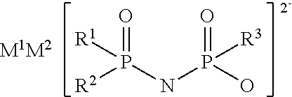
An electrolytic solution for a non-aqueous electrolyte battery is provided, which is capable of providing an excellent low-temperature output characteristic at -30.degree. C. or lower and an excellent cycle characteristic at high temperatures of 45.degree. C. or higher. For example, the electrolytic solution contains the following salt having a divalent imide anion. ##STR00001## wherein R.sup.1 to R.sup.3 represent a fluorine atom or an alkoxy group, for example, and M.sup.1 and M.sup.2 represent protons or metal cations, for example.
| Inventors: | Morinaka; Takayoshi (Ube, JP), Kubo; Makoto (Ube, JP), Kawabata; Wataru (Ube, JP), Yamamoto; Kenta (Saitama, JP), Takahashi; Mikihiro (Ube, JP) | ||||||||||
|---|---|---|---|---|---|---|---|---|---|---|---|
| Applicant: |
|
||||||||||
| Assignee: | CENTRAL GLASS CO., LTD.
(Yamaguchi, JP) |
||||||||||
| Family ID: | 56091714 | ||||||||||
| Appl. No.: | 15/529,738 | ||||||||||
| Filed: | December 1, 2015 | ||||||||||
| PCT Filed: | December 01, 2015 | ||||||||||
| PCT No.: | PCT/JP2015/083803 | ||||||||||
| 371(c)(1),(2),(4) Date: | May 25, 2017 | ||||||||||
| PCT Pub. No.: | WO2016/088773 | ||||||||||
| PCT Pub. Date: | June 09, 2016 |
Prior Publication Data
| Document Identifier | Publication Date | |
|---|---|---|
| US 20170331143 A1 | Nov 16, 2017 | |
Foreign Application Priority Data
| Dec 1, 2014 [JP] | 2014-243288 | |||
| Current U.S. Class: | 1/1 |
| Current CPC Class: | H01M 10/052 (20130101); H01M 10/0563 (20130101); H01M 10/0567 (20130101); H01M 10/054 (20130101); H01M 2300/002 (20130101); Y02E 60/10 (20130101); H01M 10/0569 (20130101); H01M 10/0568 (20130101); Y02T 10/70 (20130101) |
| Current International Class: | H01M 10/0567 (20100101); H01M 10/0563 (20100101); H01M 10/054 (20100101); H01M 10/052 (20100101); H01M 10/0568 (20100101); H01M 10/0569 (20100101) |
References Cited [Referenced By]
U.S. Patent Documents
| 2014/0193706 | July 2014 | Morinaka et al. |
| 2015/0118579 | April 2015 | Kondo et al. |
| 2017/0204124 | July 2017 | Takahashi |
| 102816096 | Dec 2012 | CN | |||
| 104151206 | Nov 2014 | CN | |||
| 2000-123867 | Apr 2000 | JP | |||
| 2013-30465 | Feb 2013 | JP | |||
| 2013-51122 | Mar 2013 | JP | |||
| 201401613 | Jan 2014 | TW | |||
Other References
|
International Search Report dated Jan. 12, 2016 International (PCT) Application No. PCT/JP2015/083803. cited by applicant . Office Action dated Aug. 30, 2016 in corresponding Taiwan Application No. 104140196, with English translation. cited by applicant. |
Primary Examiner: Crepeau; Jonathan
Attorney, Agent or Firm: Wenderoth, Lind & Ponack, L.L.P.
Claims
What is claimed is:
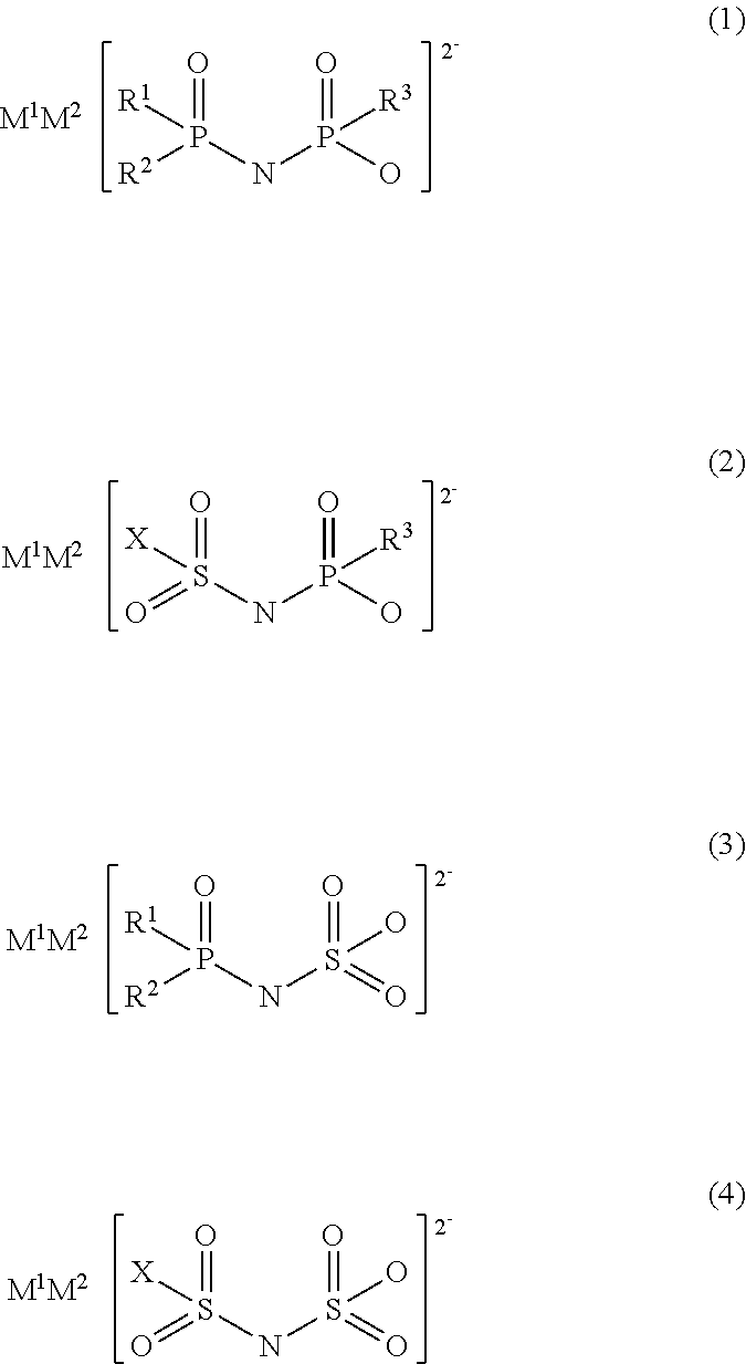
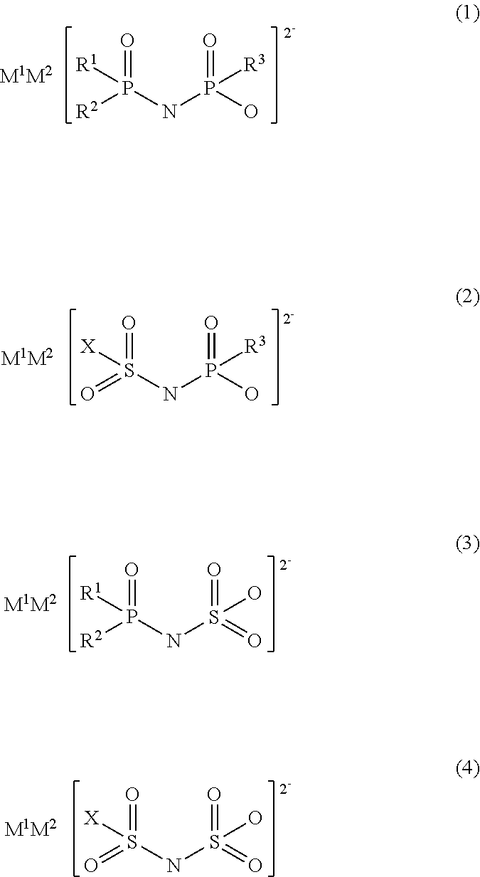
1. An electrolytic solution for a non-aqueous electrolyte battery, comprising a non-aqueous solvent, a solute, and at least one salt having a divalent imide anion represented by any one of the following general formulae (1) to (4): ##STR00007## wherein: in formulae (1) to (3), R.sup.1 to R.sup.3 each independently represent a fluorine atom or an organic group selected from a linear or branched C1-10 alkoxy group, a C2-10 alkenyloxy group, a C2-10 alkynyloxy group, a C3-10 cycloalkoxy group, a C3-10 cycloalkenyloxy group and a C6-10 aryloxy group, wherein a fluorine atom, an oxygen atom or an unsaturated bond may also be present in the organic group; in formulae (2) and (4), X represents a fluorine atom or an organic group selected from a linear or branched C1-10 alkyl group, a C2-10 alkenyl group, a C2-10 alkynyl group, a C3-10 cycloalkyl group, a C3-10 cycloalkenyl group, a C6-10 aryl group, a linear or branched C1-10 alkoxy group, a C2-10 alkenyloxy group, a C2-10 alkynyloxy group, a C3-10 cycloalkoxy group, a C3-10 cycloalkenyloxy group and a C6-10 aryloxy group, wherein a fluorine atom, an oxygen atom, or an unsaturated bond may also be present in the organic group; and M.sup.1 and M.sup.2 each independently represent a proton, a metal cation or an onium cation.
2. The electrolytic solution according to claim 1, wherein said salt has at least one P--F bond or S--F bond.
3. The electrolytic solution according to claim 1, wherein said R.sup.1 to R.sup.3 represent a fluorine atom or an organic group selected from the group consisting of a C2-10 alkenyloxy group and a C2-10 alkynyloxy group.
4. The electrolytic solution according to claim 3, wherein said alkenyloxy group is selected from the group consisting of a 1-propenyloxy group, a 2-propenyloxy group, and a 3-butenyloxy group, and said alkynyloxy group is selected from the group consisting of a 2-propynyloxy group, and 1,1-dimethyl-2-propynyloxy group.
5. The electrolytic solution according to claim 1, wherein said X is a fluorine atom or an organic group selected from the group consisting of a C1-10 alkoxy group, a C2-10 alkenyloxy group and a C2-10 alkynyloxy group.
6. The electrolytic solution according to claim 5, wherein said alkoxy group is selected from the group consisting of a methoxy group, an ethoxy group and a propoxy group; said alkenyloxy group is selected from the group consisting of a 1-propenyloxy group, a 2-propenyloxy group and a 3-butenyloxy group; and said alkynyloxy group is selected from the group consisting of a 2-propynyloxy group and a 1,1-dimethyl-2-propynyloxy group.
7. The electrolytic solution according to claim 1, wherein the counter cations M.sup.1 and M.sup.2 of the imide anion in said salt represent at least one cation selected from the group consisting of a proton, a lithium ion, a sodium ion, a potassium ion, a tetraalkylammonium ion, and a tetraalkylphosphonium ion.
8. The electrolytic solution according to claim 7, wherein the concentration of said salt ranges from 0.01 to 5.0 mass % relative to the total amount of the electrolytic solution.
9. The electrolytic solution according to claim 8, wherein said solute is at least one solute selected from the group consisting of LiPF.sub.6, LiPF.sub.2(C.sub.2O.sub.4).sub.2, LiPF.sub.4(C.sub.2O.sub.4), LiP(C.sub.2O.sub.4).sub.3, LiBF.sub.2(C.sub.2O.sub.4), LiB(C.sub.2O.sub.4).sub.2, LiPO.sub.2F.sub.2, LiN(F.sub.2PO).sub.2, LiN(FSO.sub.2).sub.2, LiN(CF.sub.3SO.sub.2).sub.2, LiBF.sub.4, NaPF.sub.6, NaPF.sub.2(C.sub.2O.sub.4).sub.2, NaPF.sub.4(C.sub.2O.sub.4), NaP(C.sub.2O.sub.4).sub.3, NaBF.sub.2(C.sub.2O.sub.4), NaB(C.sub.2O.sub.4).sub.2, NaPO.sub.2F.sub.2, NaN(F.sub.2PO).sub.2, NaN(FSO.sub.2).sub.2, NaN(CF.sub.3SO.sub.2).sub.2 and NaBF.sub.4.
10. The electrolytic solution according to claim 9, wherein said non-aqueous solvent is at least one non-aqueous solvent selected from the group consisting of a cyclic carbonate, a linear carbonate, a cyclic ester, a linear ester, a cyclic ether, a linear ether, a sulfone compound, a sulfoxide compound and an ionic liquid.
11. A non-aqueous electrolyte battery comprising at least a positive electrode, a negative electrode, and the electrolytic solution for a non-aqueous electrolyte battery according to claim 1.
Description
TECHNICAL FIELD
The present invention relates to an electrolytic solution to be used for a non-aqueous electrolyte secondary battery excellent in a cycle characteristic and a low-temperature characteristic, as well as a non-aqueous electrolyte battery using the same.
BACKGROUND ART
In recent years, power storage systems to be applied for small apparatuses that need high energy density, such as information technology-related apparatuses or communication apparatuses, specifically, personal computers, video cameras, digital still cameras, and cell phones, and power storage systems to be applied for large apparatuses that need power, such as electric vehicles, hybrid vehicles, auxiliary power for fuel cell vehicles, and energy storage have received attention. As a candidate therefor, non-aqueous electrolyte batteries such as a lithium ion battery, a lithium battery, a lithium ion capacitor, or a sodium ion battery, have been actively developed.
Many of these non-aqueous electrolyte batteries have already been put into practical use, however, none of these batteries are sufficient for various applications in terms of respective characteristics. In particular, a battery to be applied for a vehicle such as an electric vehicle is required to have a high input output characteristic even in a cold season. Hence, improvement in a low-temperature characteristic is important. Moreover, such a battery is required to have a high-temperature cycle characteristic such that it is capable of maintaining its characteristics (less increase in internal resistance) even when charging and discharging are performed repeatedly under a high-temperature environment.
As a means for improving the high-temperature characteristic, and the battery characteristics (a cycle characteristic) wherein charging and discharging are repeated, optimization of various battery components including active materials of positive electrodes and negative electrodes has been studied. A non-aqueous electrolytic solution-related technology is not an exception, and it has been proposed that deterioration due to decomposition of an electrolytic solution on the surface of an active positive electrode or an active negative electrode is suppressed by various additives. For example, Patent Document 1 proposes that battery characteristics are improved by the addition of a vinylene carbonate to an electrolytic solution. However, this is problematic in that battery characteristics at high temperatures are improved, but the internal resistance is significantly increased to lower the low-temperature characteristic. Furthermore, a number of examinations on the addition of an imide salt to an electrolytic solution have been conducted. For example, there have been proposed a method (Patent Document 2) for suppressing deterioration in a high-temperature cycle characteristic or a high-temperature storage characteristic by combining a specific sulfonimide salt or a phosphoryl imide salt with an oxalato complex, and a method (Patent Document 3) for suppressing deterioration in a cycle characteristic or an output characteristic by combining a specific sulfonimide salt with a fluorophosphate.
PRIOR ART DOCUMENTS
Patent Documents
Patent Document 1: JP Patent Publication (Kokai) No. 2000-123867A
Patent Document 2: JP Patent Publication (Kokai) No. 2013-051122A
Patent Document 3: JP Patent Publication (Kokai) No. 2013-030465A
SUMMARY OF THE INVENTION
Problems to be Solved by the Invention
A low-temperature characteristic and a high-temperature cycle characteristic provided by non-aqueous electrolyte batteries using non-aqueous electrolytic solutions disclosed in the prior art documents are not completely satisfactory and still remain to be improved. The present invention provides an electrolytic solution to be used for a non-aqueous electrolyte battery capable of providing a good low-temperature output characteristic at -30.degree. C. or lower and a good cycle characteristic at high temperatures of 45.degree. C. or higher, as well as a non-aqueous electrolyte battery using the same.
Means for Solving the Problems
Intensive studies have been made in order to solve the problems, and as a result, the present inventors have discovered that a non-aqueous electrolyte battery can provide a good low-temperature output characteristic and a high-temperature cycle characteristic, by introducing a specific salt having a divalent imide anion with a specific structure into a non-aqueous electrolytic solution to be used for a non-aqueous electrolyte battery comprising a non-aqueous solvent and a solute contains and then using the resultant non-aqueous electrolyte in the non-aqueous electrolyte battery. Based on this finding, the present invention has been completed.
Specifically, the present invention provides an electrolytic solution to be used for a non-aqueous electrolyte battery (hereafter, also referred to as simply "non-aqueous electrolytic solution" or "electrolytic solution") comprising a non-aqueous solvent, a solute, and at least one type of salt having a divalent imide anion (hereafter, also referred to as simply "salt having an imide anion") represented by any one of the following general formulae (1) to (4).
##STR00002##
wherein, in formulae (1) to (3), R.sup.1 to R.sup.3 each independently represent a fluorine atom or an organic group selected from a linear or branched C1-10 alkoxy group, a C2-10 alkenyloxy group, a C2-10 alkynyloxy group, a C3-10 cycloalkoxy group, a C3-10 cycloalkenyloxy group and a C6-10 aryloxy group, wherein a fluorine atom, an oxygen atom or an unsaturated bond may also be present in the organic group;
in formulae (2) and (4), X represents a fluorine atom or an organic group selected from a linear or branched C1-10 alkyl group, a C2-10 alkenyl group, a C2-10 alkynyl group, a C3-10 cycloalkyl group, a C3-10 cycloalkenyl group, a C6-10 aryl group, a linear or branched C1-10 alkoxy group, a C2-10 alkenyloxy group, a C2-10 alkynyloxy group, a C3-10 cycloalkoxy group, a C3-10 cycloalkenyloxy group and a C6-10 aryloxy group, wherein a fluorine atom, an oxygen atom, or an unsaturated bond may also be present in the organic group; and
M.sup.1 and M.sup.2 each independently represent a proton, a metal cation or an onium cation.
The action mechanism for improving battery characteristics in accordance with the present invention is not clearly understood. However, it is considered that a salt having an imide anion of the present invention is partially decomposed at the boundary between a positive electrode and an electrolytic solution, and the boundary between a negative electrode and the electrolytic solution, so as to forma film. The film prevents the decomposition of a non-aqueous solvent or a solute by inhibiting a direct contact between the non-aqueous solvent or the solute with an active material, so as to suppress the deterioration of the battery performances. While the mechanism thereof is unclear, it is important that an imide anion has a phosphate ion site (--P(.dbd.O)R.sup.3O.sup.-) or a sulfonate ion site (--SO.sub.3.sup.-). It is considered that incorporation of a phosphate ion site or a sulfonate ion site into the above film results in uneven distribution of electric charge of the thus formed film, which leads to a high lithium conductivity; that is, a low resistance (film having a good output characteristic). Furthermore, the above effect is considered to be that an imide anion contains a site with a high electron-withdrawing property (e.g., a fluorine atom and a fluorine-containing alkoxy group) to further increase the degree of uneven distribution of electric charge, so as to form a film with a lower resistance (film having a better output characteristic). For this reason, it is assumed that an effect of improving a high-temperature cycle characteristic and a low-temperature output characteristic is exerted by the non-aqueous electrolytic solution containing a salt having an imide anion according to the present invention.
The salt having an imide anion preferably has at least one P--F bond or S--F bond, in order to have a better low-temperature characteristic. The salt further preferably has as many P--F bonds or S--F bonds as possible, since the higher the number of P--F bonds or S--F bonds in the salt, the more the low-temperature characteristic can be improved.
It is preferable that the above R.sup.1 to R.sup.3 are a fluorine atom or an organic group selected from the group consisting of a C2-10 alkenyloxy group and a C2-10 alkynyloxy group, in order to obtain a better high-temperature cycle characteristic.
Furthermore, the number of carbons of the above alkenyloxy group is preferably 6 or less. The higher number of carbons tends to provide a relatively higher internal resistance when a film is formed on an electrode. The number of carbons is preferably 6 or less because the resulting internal resistance tends to be low. The alkenyloxy group is particularly preferably selected from the group consisting of a 1-propenyloxy group, a 2-propenyloxy group, and a 3-butenyloxy group in order to obtain a non-aqueous electrolyte battery excellent in a high-temperature cycle characteristic and a low-temperature output characteristic.
Furthermore, the number of carbons of the above alkynyloxy group is preferably 6 or less. The higher number of carbons tends to provide a relatively high internal resistance when a film is formed on an electrode. The number of carbons is preferably 6 or less, because the resulting internal resistance tends to be low. The alkynyloxy group is particularly preferably selected from the group consisting of a 2-propynyloxy group, and 1,1-dimethyl-2-propynyloxy group in order to obtain a non-aqueous electrolyte battery excellent in a high-temperature cycle characteristic and a low-temperature output characteristic.
The above X is preferably a fluorine atom or an organic group selected from the group consisting of a C1-10 alkoxy group, a C2-10 alkenyloxy group, and a C2-10 alkynyloxy group in order to obtain a better high-temperature cycle characteristic.
The number of carbons of the above alkoxy group is preferably 6 or less. The higher number of carbons tends to provide a relatively high internal resistance when a film is formed on an electrode. The number of carbons is preferably 6 or less, because the resulting internal resistance tends to be low. The alkoxy group is particularly preferably selected from the group consisting of a methoxy group, an ethoxy group, and a propoxy group in order to obtain a non-aqueous electrolyte battery excellent in a high-temperature cycle characteristic and a low-temperature output characteristic.
The number of carbons of the above alkenyloxy group is preferably 6 or less. The higher number of carbons tends to provide a relatively high internal resistance when a film is formed on an electrode. The number of carbons is preferably 6 or less, because the resulting internal resistance tends to be low. The alkenyloxy group is particularly preferably selected from the group consisting of a 1-propenyloxy group, a 2-propenyloxy group, and a 3-butenyloxy group in order to obtain a non-aqueous electrolyte battery excellent in a high-temperature cycle characteristic and a low-temperature output characteristic.
The number of carbons of alkynyloxy group is preferably 6 or less. The high number of carbons tends to provide a relatively high internal resistance when a film is formed on an electrode. The number of carbons is preferably 6 or less because the resulting internal resistance tends to be low. The alkynyloxy group is particularly preferably selected from the group consisting of a 2-propynyloxy group and a 1,1-dimethyl-2-propynyloxy group in order to obtain a non-aqueous electrolyte battery excellent in a high-temperature cycle characteristic and a low-temperature output characteristic.
Counter cations M.sup.1 and M.sup.2 of an imide anion in the above salt preferably represent protons, alkali metal cations, or onium cations. Of these, in view of solubility and ion electric conductivity in a non-aqueous electrolytic solution, a counter cation is more preferably at least one cation selected from the group consisting of a proton, a lithium ion, a sodium ion, a potassium ion, a tetraalkylammonium ion, and a tetraalkylphosphonium ion.
The lower limit of the concentration of the salt is preferably 0.01 mass % or more, more preferably 0.05 mass % or more, and further more preferably 0.1 mass % or more relative to the total amount of an electrolytic solution for a non-aqueous electrolyte battery. Furthermore, the upper limit of the concentration is preferably 5.0 mass % or less, more preferably 4.0 mass % or less, and further more preferably 3.0 mass % or less. The concentration that is lower than 0.01 mass % makes it difficult to sufficiently obtain an effect of improving battery characteristics, so that such a concentration is not preferred. On the other hand, the concentration of higher than 5.0 mass % does not improve the effect further and thus is not only useless, but also such concentration tends to increase the viscosity of the electrolytic solution and decrease the ionic conductance, which leads to easily increase the resistance and deteriorate the battery performance, and thus is not preferred. These salts may be used singly as long as its concentration does not exceed 5.0 mass %, or they can be used as a combination of two or more kinds of the salts at any ratio, depending on applications.
The above solute is preferably at least one solute selected from the group consisting of LiPF.sub.6, LiPF.sub.2(C.sub.2O.sub.4).sub.2, LiPF.sub.4(C.sub.2O.sub.4), LiP(C.sub.2O.sub.4).sub.3, LiBF.sub.2(C.sub.2O.sub.4) LiB(C.sub.2O.sub.4).sub.2, LiPO.sub.2F.sub.2, LiN(F.sub.2PO).sub.2, LiN(FSO.sub.2).sub.2, LiN(CF.sub.3SO.sub.2).sub.2, LiBF.sub.4, NaPF.sub.6, NaPF.sub.2(C.sub.2O.sub.4).sub.2, NaPF.sub.4(C.sub.2O.sub.4), NaP(C.sub.2O.sub.4).sub.3, NaBF.sub.2(C.sub.2O.sub.4), NaB(C.sub.2O.sub.4).sub.2, NaPO.sub.2F.sub.2, NaN(F.sub.2PO).sub.2, NaN(FSO.sub.2).sub.2, NaN(CF.sub.3SO.sub.2).sub.2, and NaBF.sub.4.
The above non-aqueous solvent is preferably at least one solvent selected from the group consisting of a cyclic carbonate, a linear carbonate, a cyclic ester, a linear ester, a cyclic ether, a linear ether, a sulfone compound, a sulfoxide compound, and an ionic liquid.
The present invention further provides a non-aqueous electrolyte battery comprising at least a positive electrode, a negative electrode, and the above electrolytic solution for a non-aqueous electrolyte battery.
Effect of the Invention
When the present electrolytic solution is used for a non-aqueous electrolyte battery, the resultant battery can exert a good low-temperature output characteristic at -30.degree. C. or lower and a good cycle characteristic at high temperatures of 45.degree. C. or higher.
MODES FOR CARRYING OUT THE INVENTION
The present invention will be explained in detail as follows. However, explanations for constituent features described below are merely examples of the embodiments of the present invention, and the present invention is not limited to these specific contents and may be variously modified within the disclosure of the present specification.
The present electrolytic solution is an electrolytic solution for a non-aqueous electrolyte battery characterized by comprising a non-aqueous solvent, a solute, and at least one salt having a divalent imide anion, which is represented by any one of the general formulae (1) to (4).
##STR00003##
In formulae (1) to (3), R.sup.1 to R.sup.3 each independently represent a fluorine atom or an organic group selected from a linear or branched C1-10 alkoxy group, a C2-10 alkenyloxy group, a C2-10 alkynyloxy group, a C3-10 cycloalkoxy group, a C3-10 cycloalkenyloxy group and a C6-10 aryloxy group, wherein a fluorine atom, an oxygen atom, or an unsaturated bond may be present in the organic group.
In formulae (2) and (4), X represents a fluorine atom or an organic group selected from a linear or branched C1-10 alkyl group, a C2-10 alkenyl group, a C2-10 alkynyl group, a C3-10 cycloalkyl group, a C3-10 cycloalkenyl group, a C6-10 aryl group, a linear or branched C1-10 alkoxy groups, a C2-10 alkenyloxy group, a C2-10 alkynyloxy group, a C3-10 cycloalkoxy group, a C3-10 cycloalkenyloxy group and a C6-10 aryloxy group, wherein a fluorine atom, an oxygen atom or an unsaturated bond may be also present in the organic group.
M.sup.1 and M.sup.2 as counter cations each independently represent a proton, a metal cation or an onium cation.
Examples of the counter cation include a proton, alkali metal cations such as a lithium ion, a sodium ion, and a potassium ion, alkaline earth metal cations such as a magnesium ion and a calcium ion, onium cations such as tetramethyl ammonium, tetraethyl ammonium, and tetrabutylphosphonium (when counter cations are monovalent cations, 2 kinds of the counter cations may be mixed. Moreover, for example, if M.sup.1 is a divalent cation, M.sup.2 does not exist).
In the above formulae (1) to (3), examples of those represented by R.sup.1 to R.sup.3, specifically: examples of alkoxy groups include C1-10 alkoxy groups and fluorine-containing alkoxy groups such as a methoxy group, an ethoxy group, a propoxy group, an isopropoxy group, a butoxy group, a secondary butoxy group, a tertiary butoxy group, a pentyloxy group, a trifluoromethoxy group, a 2,2-difluoroethoxy group, a 2,2,2-trifluoroethoxy group, a 2,2,3,3-tetrafluoropropoxy group and a 1,1,1,3,3,3-hexafluoroisopropoxy group; examples of alkenyloxy groups include C2-10 alkenyloxy groups and fluorine-containing alkenyloxy groups such as a vinyloxy group, a 1-propenyloxy group, a 2-propenyloxy group, an isopropenyloxy group, a 2-butenyloxy group, a 3-butenyloxy group and a 1,3-butadienyloxy group; examples of alkynyloxy groups include C2-10 alkynyloxy groups and fluorine-containing alkynyloxy groups such as an ethynyloxy group, a 2-propynyloxy group, and a 1,1-dimethyl-2-propynyloxy group; examples of cycloalkoxy groups include C3-10 cycloalkoxy groups and fluorine-containing cycloalkoxy groups such as a cyclopentyloxy group and a cyclohexyloxy group; examples of cycloalkenyloxy groups include C3-10 cycloalkenyloxy groups and fluorine-containing cycloalkenyloxy groups such as a cyclo pentenyloxy group and a cyclohexenyloxy group; and examples of aryloxy groups include C6-10 aryloxy groups and fluorine-containing aryloxy groups such as a phenyloxy group, a tolyloxy group and a xylyloxy group.
In the above general formulae (2) and (4), those represented by X, specifically: examples of alkyl groups include C1-10 alkyl groups and fluorine-containing alkyl groups such as a methyl group, an ethyl group, a propyl group, an isopropyl group, a butyl group, a secondary butyl group, a tertiary butyl group, a pentyl group, a trifluoromethyl group, a 2,2-difluoroethyl group, a 2,2,2-trifluoroethyl group, a 2,2,3,3-tetrafluoropropyl group and a 1,1,1,3,3,3-hexafluoroisopropyl group; examples of alkenyl groups include C2-10 alkenyl groups and fluorine-containing alkenyl groups such as a vinyl group, a 1-propenyl group, a 2-propenyl group, an isopropenyl group, a 2-butenyl group, a 3-butenyl group and a 1,3-butadienyl group; examples of alkynyl groups include C2-10 alkynyl groups and fluorine-containing alkynyl groups such as an ethynyl group, a 2-propynyl group and 1,1-dimethyl-2-propynyl group; examples of cycloalkyl groups include C3-10 cycloalkyl groups and fluorine-containing cycloalkyl groups such as a cyclopentyl group and a cyclohexyl group; examples of cycloalkenyl groups include C3-10 cycloalkenyl groups and fluorine-containing cycloalkenyl groups such as a cyclopentenyl group and a cyclohexenyl group; and examples of aryl groups include C6-10 aryl groups and fluorine-containing aryl groups such as a phenyl group, a tolyl group and a xylyl group.
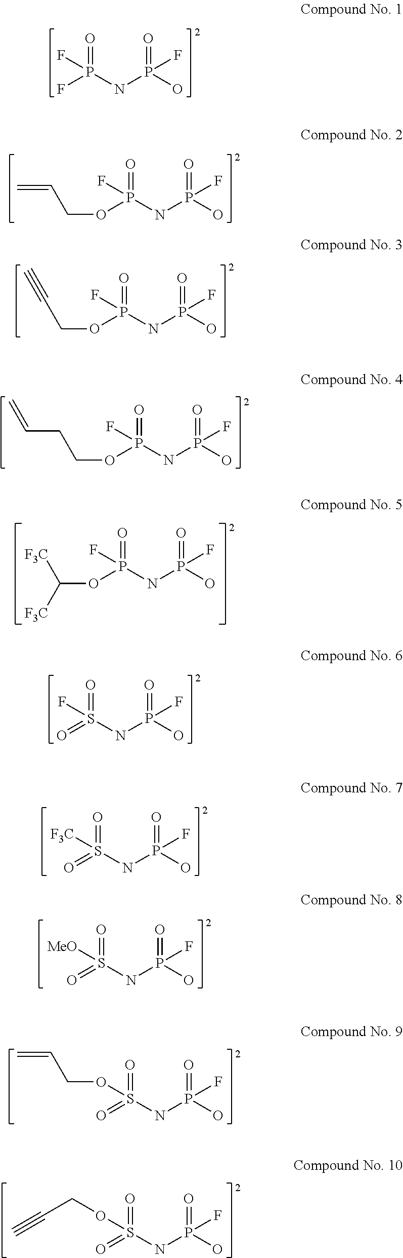
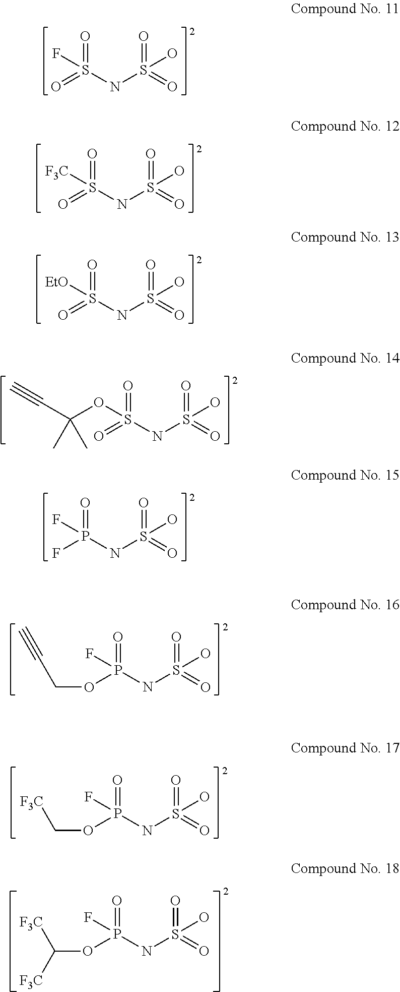
Examples of the divalent imide anions described in the above general formulae (1) to (4) include, more specifically, the following compounds No. 1 to No. 18. However, the imide anions to be used in the present invention are not limited in any way by the following examples.
##STR00004## ##STR00005##
The salts having the imide anions, which are represented by any one of the above general formulae (1) to (4), can be produced by various methods. While production processes therefor are not limited, for example, the salts can be obtained by reacting the corresponding phosphoramide (H.sub.2NP(.dbd.O) R.sup.3O.sup.-) or sulfamic acid (H.sub.2NSO.sub.3.sup.-) with the corresponding phosphonyl chloride (P(.dbd.O)R.sup.1R.sup.2Cl) or sulfonyl chloride (XSO.sub.2Cl) in the presence of an organic base or an inorganic base.
The kinds of the non-aqueous solvent to be used for the electrolytic solution of the present invention are not particularly limited, and any kinds of the non-aqueous solvents can be used. The specific examples thereof include cyclic carbonates such as propylene carbonate, ethylene carbonate, and butylene carbonate, linear carbonates such as diethyl carbonate, dimethyl carbonate, and ethyl methyl carbonate, cyclic esters such as .gamma.-butyrolactone and .gamma.-valerolactone, linear esters such as methyl acetate and methyl propionate, cyclic ethers such as tetrahydrofuran, 2-methyltetrahydrofuran, and dioxane, linear ethers such as dimethoxyethane and diethylether, and sulfone compounds or sulfoxide compounds such as dimethyl sulfoxide and sulfolane. Another example thereof in a category differing from non-aqueous solvents is an ionic liquid and the like. Furthermore, the non-aqueous solvents to be used in the present invention may be used singly or a combination of two or more solvents mixed at any ratio depending on applications. Of these examples, in view of electrochemical stability against its oxidation-reduction and chemical stability relating to heat or reaction with the above solute, particularly propylene carbonate, ethylene carbonate, diethyl carbonate, dimethyl carbonate, and ethyl methyl carbonate are preferred.
The kinds of the above solutes to be used for the electrolytic solution for a non-aqueous electrolyte battery of the present invention are not particularly limited, and any electrolytic salts can be used. The specific examples thereof include: in the case of a lithium battery and a lithium ion battery, electrolytic salts represented by LiPF.sub.6, LiPF.sub.2(O.sub.2O.sub.4).sub.2, LiPF.sub.4(C.sub.2O.sub.4), LiP(C.sub.2O.sub.4).sub.3, LiBF.sub.2(C.sub.2O.sub.4), LiB(C.sub.2O.sub.4).sub.2, LiPO.sub.2F.sub.2, LiN(F.sub.2PO).sub.2, LiN(FSO.sub.2).sub.2, LiN(CF.sub.3SO.sub.2).sub.2, LiBF.sub.4, LiClO.sub.4, LiAsF.sub.6, LiSbF.sub.6, LiCF.sub.3SO.sub.3, LiN(C.sub.2F.sub.5SO.sub.2).sub.2, LiN(CF.sub.3SO.sub.2)(C.sub.4F.sub.9SO.sub.2), LiC(CF.sub.3SO.sub.2).sub.3, LiPF.sub.3(C.sub.3F.sub.7).sub.3, LiB(CF.sub.3).sub.4, and LiBF.sub.3(C.sub.2F.sub.5); and in the case of a sodium ion battery, electrolytic salts represented by NaPF.sub.6, NaPF.sub.2(C.sub.2O.sub.4).sub.2, NaPF.sub.4(C.sub.2O.sub.4), NaP(C.sub.2O.sub.4).sub.3, NaBF.sub.2(C.sub.2O.sub.4), NaB(C.sub.2O.sub.4).sub.2, NaPO.sub.2F.sub.2, NaN(F.sub.2PO).sub.2, NaN(FSO.sub.2).sub.2, NaN(CF.sub.3SO.sub.2).sub.2, NaBF.sub.4, NaClO.sub.4, NaAsF.sub.6, NaSbF.sub.6, NaCF.sub.3SO.sub.3, NaN(C.sub.2F.sub.5SO.sub.2).sub.2, NaN(CF.sub.3SO.sub.2)(C.sub.4F.sub.9SO.sub.2), NaC(CF.sub.3SO.sub.2).sub.3, NaPF.sub.3(C.sub.3F.sub.7).sub.3, NaB(CF.sub.3).sub.4, and NaBF.sub.3(O.sub.2F.sub.5). These solutes may be used singly or in a combination of two or more solutes mixed at any ratio depending on applications. Of these examples, in view of energy density, output characteristics, life, and the like for a battery, LiPF.sub.6, LiPF.sub.2(C.sub.2O.sub.4).sub.2, LiPF.sub.4(C.sub.2O.sub.4), LiP(C.sub.2O.sub.4).sub.3, LiBF.sub.2(C.sub.2O.sub.4), LiB(C.sub.2O.sub.4).sub.2, LiPO.sub.2F.sub.2, LiN(F.sub.2PO).sub.2, LiN(FSO.sub.2).sub.2, LiN(CF.sub.3SO.sub.2).sub.2, LiBF.sub.4, NaPF.sub.6, NaPF.sub.2(C.sub.2O.sub.4).sub.2, NaPF.sub.4(C.sub.2O.sub.4), NaP(C.sub.2O.sub.4).sub.3, NaBF.sub.2(C.sub.2O.sub.4), NaB(C.sub.2O.sub.4).sub.2, NaPO.sub.2F.sub.2, NaN(F.sub.2PO).sub.2, NaN(FSO.sub.2).sub.2, NaN(CF.sub.3SO.sub.2).sub.2, and NaBF.sub.4 are preferred.
A preferable combination of the solutes is, for example, a combination of at least one solute selected from the group consisting of LiPF.sub.2(C.sub.2O.sub.4).sub.2, LiPF.sub.4(C.sub.2O.sub.4), LiP(O.sub.2O.sub.4).sub.3, LiBF.sub.2(C.sub.2O.sub.4), LiB(C.sub.2O.sub.4).sub.2, LiPO.sub.2F.sub.2, LiN(F.sub.2PO).sub.2, LiN(FSO.sub.2).sub.2, LiN(CF.sub.3SO.sub.2).sub.2, and LiBF.sub.4, with LiPF.sub.6.
The ratio (molar ratio when LiPF.sub.6 is used as 1 mole) generally ranges from 1:0.001 to 1:0.5, and preferably ranges from 1:0.01 to 1:0.2, when at least one solute selected from the group consisting of LiPF.sub.2(C.sub.2O.sub.4).sub.2, LiPF.sub.4(C.sub.2O.sub.4), LiP(C.sub.2O.sub.4).sub.3, LiBF.sub.2(C.sub.2O.sub.4), LiB(C.sub.2O.sub.4).sub.2, LiPO.sub.2F.sub.2, LiN(F.sub.2PO).sub.2, LiN(FSO.sub.2).sub.2, LiN(CF.sub.3SO.sub.2).sub.2 and LiBF.sub.4 is used in combination with LiPF.sub.6 as solutes. The use of solutes in combination at the above ratio can provide an effect of further improving various battery characteristics. On the other hand, if the proportion of LiPF.sub.6 is lower than that in the case of 1:0.5, the ionic conductance of the electrolytic solution is lowered, and the resistance tends to increase.
While the concentration of these solutes is not particularly limited, the lower limit thereof is preferably 0.5 mol/L or more, more preferably 0.7 mol/L or more, and further preferably 0.9 mol/L or more. Moreover, the upper limit thereof is preferably 2.5 mol/L or less, more preferably 2.0 mol/L or less, and further preferably 1.5 mol/L or less. In this case, when plural kinds of the solutes are used, the concentration of the total amount of the solutes is preferably within the above range. If the concentration is lower than 0.5 mol/L, ionic conductance is lowered, and the cycle characteristic and output characteristic of the non-aqueous electrolyte battery tend to decrease. On the other hand, if the concentration exceeds 2.5 mol/L, the viscosity of the electrolytic solution for a non-aqueous electrolyte battery is increased, and as a result the ionic conductance tends to decrease. Accordingly, there is a risk of lowering the cycle characteristics and the output characteristics of the non-aqueous electrolyte battery.
When a large amount of the solutes is dissolved at once in a non-aqueous solvent, the liquid temperature may increase because of the heat of the dissolution of the solute(s). If the liquid temperature increases remarkable, the decomposition of the fluorine-containing electrolytic salt is accelerated and thus hydrogen fluoride may be generated. Hydrogen fluoride causes deterioration in battery performance and thus is not preferred. Therefore, while the liquid temperature at which the solute(s) is dissolved in a non-aqueous solvent is not particularly limited, -20.degree. C. to 80.degree. C. is preferably, and 0.degree. C. to 60.degree. C. is more preferably.
The basic constitution of the electrolytic solution for a non-aqueous electrolyte battery of the present invention is as described above. An additive that is generally used may be added at any ratio to the electrolytic solution for a non-aqueous electrolyte battery of the present invention, as long as the gist of the present invention is not impaired. Specific examples thereof include compounds having an effect of preventing overcharge, an effect of forming a negative electrode film, and an effect of protecting a positive electrode, such as cyclohexylbenzene, biphenyl, t-butylbenzene, vinylene carbonate, vinyl ethylene carbonate, difluoroanisole, fluoroethylene carbonate, propane sultone, succinonitrile, and dimethyl vinylene carbonate. Moreover, as used in a non-aqueous electrolyte battery referred to as a lithium polymer battery, an electrolytic solution for a non-aqueous electrolyte battery can be pseudo-solidified with a gelling agent or a cross-linked polymer and then used.
Next, the constitution of the non-aqueous electrolyte battery of the present invention will be explained. The non-aqueous electrolyte battery of the present invention is characterized by the use of the above electrolytic solution for a non-aqueous electrolyte battery of the present invention. Members that are generally used for a non-aqueous electrolyte battery are used as other constitutional members. Specifically, such a battery is composed of, for example, a positive electrode, a negative electrode capable of occluding and releasing cations, a collector, a separator, and a container.
Examples of an negative electrode material to be used herein are not particularly limited. However, in the case of a lithium battery and a lithium ion battery, they include a lithium metal, an alloy of a lithium metal and another metal, or intermetallic compounds, various carbon materials (e.g., artificial graphite and natural graphite), a metal oxide, a metal nitride, tin (elemental substance), a tin compound, silicon (elemental substance), a silicon compound, an activated carbon, and a conductive polymer.
Examples of carbon materials include easily graphitizable carbon, hardly graphitizable carbon (hard carbon) having the interplanar spacing of (002) plane of 0.37 nm or more, and graphite having the interplanar spacing of (002) plane of 0.34 nm or less. More specific examples thereof include pyrolytic carbon, cokes, glassy carbon fibers, organic polymer compound fired bodies, activated carbon or carbon blacks. Of these, cokes include a pitch coke, a needle coke or a petroleum coke. An organic polymer compound fired body is referred to as a product produced by burning a phenol resin, a furan resin or the like at an appropriate temperature, to carbonize it. Carbon materials are preferred since the crystal structure changes much less due to the occlusion and release of lithium, so that a high energy density and an excellent cycle characteristic can be obtained. In addition, the shape of a carbon material may be fibrous, spherical, granular or squamous. Furthermore, amorphous carbon or a graphite material whose surface is coated with amorphous carbon is more preferred since the reactivity between the material surface and the electrolytic solution decreases.
Examples of a positive electrode material to be used herein include, but are not particularly limited to, in the case of a lithium battery and a lithium ion battery, lithium-containing transition metal composite oxides such as LiCoO.sub.2, LiNiO.sub.2, LiMnO.sub.2, and LiMn.sub.2O.sub.4, a mixture of a plurality of such lithium-containing transition metal composite oxides wherein plural kinds of transition metals, e.g., Co, Mn, and Ni, are contained, those wherein the transition metals of the lithium-containing transition metal composite oxides thereof are partially substituted with other transition metals, phosphate compounds of transition metals referred to as olivine such as LiFePO.sub.4, LiCoPO.sub.4 and LiMnPO.sub.4, oxides such as TiO.sub.2, V.sub.2O.sub.5 and MoO.sub.3, sulfides such as TiS.sub.2 and FeS, or conductive polymers such as polyacetylene, polyparaphenylene, polyaniline and polypyrrole, activated carbon, polymers that generate radicals, and carbon materials.
To a positive electrode or negative electrode material, acetylene black, Ketjen black, carbon fiber, or graphite as a conductive material and polytetrafluoroethylene, polyvinylidene fluoride, SBR resin or the like as a binder material are added, and then the resultant material is formed into a sheet, so that an electrode sheet can be produced.
As a separator for preventing the contact between a positive electrode and a negative electrode, a nonwoven fabric or porous sheet made of polypropylene, polyethylene, paper, and glass fiber is used.
A non-aqueous electrolyte battery in a coin shape, cylindrical shape, square shape, laminated aluminum sheet form, or the like is assembled with the above elements.
EXAMPLES
The present invention will be more specifically explained with reference to Examples, but the scope of the present invention is not limited by these Examples.
Example 1-1
A mixed solvent containing ethylene carbonate, propylene carbonate, dimethyl carbonate and ethyl methyl carbonate at a volume ratio of 2:1:3:4 was used as a non-aqueous solvent. LiPF.sub.6 as a solute was dissolved in the solvent to a concentration of 1.0 mol/L, and the above compound No. 1 of dilithium salt was dissolved as a salt having a divalent imide anion to a concentration of 1.0 mass %. As shown in Table 1, electrolytic solutions for non-aqueous electrolyte batteries were prepared. In addition, the above preparation was performed while maintaining the liquid temperature at 25.degree. C.
Cells were prepared using the electrolytic solution, LiNi.sub.1/3Mn.sub.1/3Co.sub.1/3O.sub.2 as a positive electrode material, and graphite as a negative electrode material. The cells were actually evaluated for a cycle characteristic and a low-temperature output characteristic of the batteries. A cell for a test was prepared as follows.
LiNi.sub.1/3Mn.sub.1/3CO.sub.1/3O.sub.2 powder (90 mass %) was mixed with 5 mass % of polyvinylidene fluoride (PVDF) as a binder and 5 mass % of acetylene black as a conductive material. N-methylpyrrolidone was further added to the mixture and then prepared into a paste. The paste was applied onto an aluminum foil, and dried, thereby preparing a positive electrode for a test. Graphite powder (90 mass %) was mixed with 10 mass % of PVDF as a binder and then N-methylpyrrolidone was further added to form a slurry. The slurry was applied onto a copper foil and dried at 150.degree. C. for 12 hours, thereby obtaining a negative electrode for the test. A polyethylene separator was impregnated with the prepared electrolytic solution, so as to assemble a 50 mAh cell armored with an aluminum laminate.
A charge and discharge test was conducted using the cells prepared by the above methods in order to evaluate a high-temperature cycle characteristic and a low-temperature output characteristic. The evaluation results are shown in Table 4.
High-Temperature Cycle Characteristics Test
The charge and discharge were conducted at an ambient temperature of 45.degree. C. to evaluate the cycle characteristic. The charging was performed to 4.3 V, and discharging was performed to 3.0 V, and then a charge and discharge cycle was repeated at current density of 5.7 mA/cm.sup.2. The cells were evaluated for the degree of the deterioration based on discharge capacity maintenance % after 200 cycles (evaluation of cycle characteristics). Discharge capacity maintenance % was determined by the following formula.
<Discharge capacity maintenance % after 200 cycles> Discharge capacity maintenance (%)=(discharge capacity after 200 cycles/initial discharge capacity).times.100 Low-Temperature Output Characteristic Test
Under an ambient temperature of 25.degree. C., a constant current and constant voltage method was conducted with an upper limit charging voltage of 4.3 V, wherein charging and discharging were performed with a current density of 0.38 mA/cm.sup.2. The discharge capacity at this time was designated as discharge capacity A. Subsequently, under an ambient temperature of -30.degree. C., a constant current and constant voltage method was conducted with an upper limit charging voltage of 4.3 V, wherein charging was performed with a current density of 0.38 mA/cm.sup.2, and then discharging was performed with a constant current density of 9.5 mA/cm.sup.2 to discharge end voltage of 3.0 V. The discharge capacity at this time was designated as discharge capacity B, a value determined by "(discharge capacity B/discharge capacity A).times.100" was designated as high output capacity maintenance (%), and was used for evaluating the low-temperature output characteristic of the cells.
Examples 1-2 to 1-155, and Comparative Examples 1-1 to 1-17
As shown in Tables 1 to 3, the electrolytic solutions for non-aqueous electrolyte batteries were prepared and cells were produced in a manner similar to Example 1-1, except that the kinds and concentrations (mol/L) of solutes and the kinds and concentrations (mass %) of the salts having imide anions were varied, and then the batteries were evaluated. The evaluation results are shown in Tables 4 to 6. In this case, the evaluation results of Examples 1-1 to 1-155 and Comparative examples 1-1 to 1-17 are indicated as relative values when the value of Comparative example 1-1 is designated as 100.
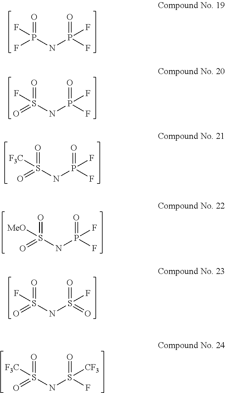
In addition, the following compounds Nos. 19 to 24 were used as the salts having imide anions used in Comparative examples 1-2 to 1-7.
##STR00006##
TABLE-US-00001 TABLE 1 Solute 1 Solute 2 Salt having imide anion Concentration Concentration Compound Counter Concentration Kind [mol/L] Kind [mol/L] No. cation [mass %] Electrolytic LiPF.sub.6 1.0 None 0 No. 1 2Li.sup.+ 1.0 solution No. 1 Electrolytic 0.005 solution No. 2 Electrolytic 0.05 solution No. 3 Electrolytic 0.1 solution No. 4 Electrolytic 0.5 solution No. 5 Electrolytic 2.0 solution No. 6 Electrolytic 10.0 solution No. 7 Electrolytic No. 2 1.0 solution No. 8 Electrolytic No. 3 1.0 solution No. 9 Electrolytic No. 4 1.0 solution No. 10 Electrolytic No. 5 1.0 solution No. 11 Electrolytic No. 6 1.0 solution No. 12 Electrolytic No. 7 1.0 solution No. 13 Electrolytic No. 8 1.0 solution No. 14 Electrolytic No. 9 1.0 solution No. 15 Electrolytic No. 10 1.0 solution No. 16 Electrolytic No. 11 1.0 solution No. 17 Electrolytic No. 12 1.0 solution No. 18 Electrolytic No. 13 1.0 solution No. 19 Electrolytic No. 14 1.0 solution No. 20 Electrolytic No. 15 1.0 solution No. 21 Electrolytic No. 16 1.0 solution No. 22 Electrolytic No. 17 1.0 solution No. 23 Electrolytic No. 18 1.0 solution No. 24 Electrolytic No. 1 Li.sup.+, H.sup.+ 1.0 solution No. 25 Electrolytic No. 6 1.0 solution No. 26 Electrolytic No. 7 1.0 solution No. 27 Electrolytic No. 10 1.0 solution No. 28 Electrolytic No. 11 1.0 solution No. 29 Electrolytic No. 15 1.0 solution No. 30 Electrolytic No. 16 1.0 solution No. 31 Electrolytic No. 1 Li.sup.+, Na.sup.+ 1.0 solution No. 32 Electrolytic No. 6 1.0 solution No. 33 Electrolytic No. 7 1.0 solution No. 34 Electrolytic No. 10 1.0 solution No. 35 Electrolytic No. 11 1.0 solution No. 36 Electrolytic No. 15 1.0 solution No. 37 Electrolytic No. 16 1.0 solution No. 38 Electrolytic No. 1 Li.sup.+, K.sup.+ 1.0 solution No. 39 Electrolytic No. 6 1.0 solution No. 40 Electrolytic No. 7 1.0 solution No. 41 Electrolytic No. 10 1.0 solution No. 42 Electrolytic No. 11 1.0 solution No. 43 Electrolytic No. 15 1.0 solution No. 44 Electrolytic No. 16 1.0 solution No. 45 Electrolytic No. 1 Li.sup.+, (C.sub.2H.sub.5).sub.4N.sup.+ 1.0 solution No. 46 Electrolytic No. 6 1.0 solution No. 47 Electrolytic No. 7 1.0 solution No. 48 Electrolytic No. 10 1.0 solution No. 49 Electrolytic No. 11 1.0 solution No. 50 Electrolytic No. 15 1.0 solution No. 51 Electrolytic No. 16 1.0 solution No. 52 Electrolytic No. 1 Li.sup.+, (C.sub.2H.sub.5).sub.4P.sup.+ 1.0 solution No. 53 Electrolytic No. 6 1.0 solution No. 54 Electrolytic No. 7 1.0 solution No. 55 Electrolytic No. 10 1.0 solution No. 56 Electrolytic No. 11 1.0 solution No. 57 Electrolytic No. 15 1.0 solution No. 58 Electrolytic No. 16 1.0 solution No. 59
TABLE-US-00002 TABLE 2 Solute 1 Solute 2 Salt having imide anion Concentration Concentration Compound Counter Concentration Kind [mol/L] Kind [mol/L] No. cation [mass %] Electrolytic LiPF.sub.6 1.0 None 0 No. 1 2Na.sup.+ 1.0 solution No. 60 Electrolytic No. 6 1.0 solution No. 61 Electrolytic No. 7 1.0 solution No. 62 Electrolytic No. 10 1.0 solution No. 63 Electrolytic No. 11 1.0 solution No. 64 Electrolytic No. 15 1.0 solution No. 65 Electrolytic No. 16 1.0 solution No. 66 Electrolytic No. 1 2(C.sub.2H.sub.5).sub.4N.sup.+ 1.0 solution No. 67 Electrolytic No. 6 1.0 solution No. 68 Electrolytic No. 7 1.0 solution No. 69 Electrolytic No. 10 1.0 solution No. 70 Electrolytic No. 11 1.0 solution No. 71 Electrolytic No. 15 1.0 solution No. 72 Electrolytic No. 16 1.0 solution No. 73 Electrolytic No. 1 2(C.sub.2H.sub.5).sub.4P.sup.+ 1.0 solution No. 74 Electrolytic No. 6 1.0 solution No. 75 Electrolytic No. 7 1.0 solution No. 76 Electrolytic No. 10 1.0 solution No. 77 Electrolytic No. 11 1.0 solution No. 78 Electrolytic No. 15 1.0 solution No. 79 Electrolytic No. 16 1.0 solution No. 80 Electrolytic LiPF.sub.2(C.sub.2O.sub.4).sub.2 0.001 No. 1 2Li.sup.+ 1.0 solution No. 81 Electrolytic 0.01 1.0 solution No. 82 Electrolytic 0.05 1.0 solution No. 83 Electrolytic 0.1 1.0 solution No. 84 Electrolytic 0.2 1.0 solution No. 85 Electrolytic 0.5 1.0 solution No. 86 Electrolytic 0.1 No. 6 1.0 solution No. 87 Electrolytic 0.1 No. 7 1.0 solution No. 88 Electrolytic 0.1 No. 10 1.0 solution No. 89 Electrolytic 0.1 No. 11 1.0 solution No. 90 Electrolytic 0.1 No. 15 1.0 solution No. 91 Electrolytic 0.1 No. 16 1.0 solution No. 92 Electrolytic LiPF.sub.4(C.sub.2O.sub.4) 0.1 No. 1 1.0 solution No. 93 Electrolytic 0.1 No. 6 1.0 solution No. 94 Electrolytic 0.1 No. 7 1.0 solution No. 95 Electrolytic 0.1 No. 10 1.0 solution No. 96 Electrolytic 0.1 No. 11 1.0 solution No. 97 Electrolytic 0.1 No. 15 1.0 solution No. 98 Electrolytic 0.1 No. 16 1.0 solution No. 99 Electrolytic LiP(C.sub.2O.sub.4).sub.3 0.1 No. 1 1.0 solution No. 100 Electrolytic 0.1 No. 6 1.0 solution No. 101 Electrolytic 0.1 No. 7 1.0 solution No. 102 Electrolytic 0.1 No. 10 1.0 solution No. 103 Electrolytic 0.1 No. 11 1.0 solution No. 104 Electrolytic 0.1 No. 15 1.0 solution No. 105 Electrolytic 0.1 No. 16 1.0 solution No. 106 Electrolytic LiBF.sub.2(C.sub.2O.sub.4) 0.1 No. 1 1.0 solution No. 107 Electrolytic 0.1 No. 6 1.0 solution No. 108 Electrolytic 0.1 No. 7 1.0 solution No. 109 Electrolytic 0.1 No. 10 1.0 solution No. 110 Electrolytic 0.1 No. 11 1.0 solution No. 111 Electrolytic 0.1 No. 15 1.0 solution No. 112 Electrolytic 0.1 No. 16 1.0 solution No. 113 Electrolytic LiB(C.sub.2O.sub.4).sub.2 0.1 No. 1 1.0 solution No. 114 Electrolytic 0.1 No. 6 1.0 solution No. 115 Electrolytic 0.1 No. 7 1.0 solution No. 116 Electrolytic 0.1 No. 10 1.0 solution No. 117 Electrolytic 0.1 No. 11 1.0 solution No. 118 Electrolytic 0.1 No. 15 1.0 solution No. 119 Electrolytic 0.1 No. 16 1.0 solution No. 120
TABLE-US-00003 TABLE 3 Solute 1 Solute 2 Salt having imide anion Concentration Concentration Compound Counter Concentration Kind [mol/L] Kind [mol/L] No. cation [mass %] Electrolytic LiPF.sub.6 1.0 LiPO.sub.2F.sub.2 0.1 No. 1 2Li.sup.+ 1.0 solution No. 121 Electrolytic 0.1 No. 6 1.0 solution No. 122 Electrolytic 0.1 No. 7 1.0 solution No. 123 Electrolytic 0.1 No. 10 1.0 solution No. 124 Electrolytic 0.1 No. 11 1.0 solution No. 125 Electrolytic 0.1 No. 15 1.0 solution No. 126 Electrolytic 0.1 No. 16 1.0 solution No. 127 Electrolytic LiN(F.sub.2PO).sub.2 0.1 No. 1 1.0 solution No. 128 Electrolytic 0.1 No. 6 1.0 solution No. 129 Electrolytic 0.1 No. 7 1.0 solution No. 130 Electrolytic 0.1 No. 10 1.0 solution No. 131 Electrolytic 0.1 No. 11 1.0 solution No. 132 Electrolytic 0.1 No. 15 1.0 solution No. 133 Electrolytic 0.1 No. 16 1.0 solution No. 134 Electrolytic LiN(FSO.sub.2).sub.2 0.1 No. 1 1.0 solution No. 135 Electrolytic 0.1 No. 6 1.0 solution No. 136 Electrolytic 0.1 No. 7 1.0 solution No. 137 Electrolytic 0.1 No. 10 1.0 solution No. 138 Electrolytic 0.1 No. 11 1.0 solution No. 139 Electrolytic 0.1 No. 15 1.0 solution No. 140 Electrolytic 0.1 No. 16 1.0 solution No. 141 Electrolytic LiN(CF.sub.3SO.sub.2).sub.2 0.1 No. 1 1.0 solution No. 142 Electrolytic 0.1 No. 6 1.0 solution No. 143 Electrolytic 0.1 No. 7 1.0 solution No. 144 Electrolytic 0.1 No. 10 1.0 solution No. 145 Electrolytic 0.1 No. 11 1.0 solution No. 146 Electrolytic 0.1 No. 15 1.0 solution No. 147 Electrolytic 0.1 No. 16 1.0 solution No. 148 Electrolytic LiBF.sub.4 0.1 No. 1 1.0 solution No. 149 Electrolytic 0.1 No. 6 1.0 solution No. 150 Electrolytic 0.1 No. 7 1.0 solution No. 151 Electrolytic 0.1 No. 10 1.0 solution No. 152 Electrolytic 0.1 No. 11 1.0 solution No. 153 Electrolytic 0.1 No. 15 1.0 solution No. 154 Electrolytic 0.1 No. 16 1.0 solution No. 155 Electrolytic None 0 None -- 0 solution No. 156 Electrolytic No. 19 Li.sup.+ 1.0 solution No. 157 Electrolytic No. 20 1.0 solution No. 158 Electrolytic No. 21 1.0 solution No. 159 Electrolytic No. 22 1.0 solution No. 160 Electrolytic No. 23 1.0 solution No. 161 Electrolytic No. 24 1.0 solution No. 162 Electrolytic LiPF.sub.2(C.sub.2O.sub.4)2 0.1 None -- 0 solution No. 163 Electrolytic LiPF.sub.4(C.sub.2O.sub.4) 0.1 0 solution No. 164 Electrolytic LiP(C.sub.2O.sub.4).sub.3 0.1 0 solution No. 165 Electrolytic LiBF.sub.2(C.sub.2O.sub.4) 0.1 0 solution No. 166 Electrolytic LiB(C.sub.2O.sub.4).sub.2 0.1 0 solution No. 167 Electrolytic LiPO.sub.2F.sub.2 0.1 0 solution No. 168 Electrolytic LiN(F.sub.2PO).sub.2 0.1 0 solution No. 169 Electrolytic LiN(FSO.sub.2).sub.2 0.1 0 solution No. 170 Electrolytic LiN(CF.sub.3SO.sub.2).sub.2 0.1 0 solution No. 171 Electrolytic LiBF.sub.4 0.1 0 solution No. 172
TABLE-US-00004 TABLE 4 Discharge capacity Negative maintenance High power Electrolytic Positive electrode after 200 capacity solution electrode Active cycles* maintenance* No. Active material material [%] [%] Example No. 1 LiNi.sub.1/3Mn.sub.1/3Co.sub.1/3O.sub.2 Graphite 120 127 1-1 Example No. 2 103 104 1-2 Example No. 3 110 110 1-3 Example No. 4 114 115 1-4 Example No. 5 117 122 1-5 Example No. 6 113 115 1-6 Example No. 7 107 105 1-7 Example No. 8 116 118 1-8 Example No. 9 117 117 1-9 Example No. 10 118 115 1-10 Example No. 11 115 117 1-11 Example No. 12 118 125 1-12 Example No. 13 113 111 1-13 Example No. 14 114 113 1-14 Example No. 15 118 114 1-15 Example No. 16 117 116 1-16 Example No. 17 115 123 1-17 Example No. 18 108 108 1-18 Example No. 19 109 107 1-19 Example No. 20 112 107 1-20 Example No. 21 117 124 1-21 Example No. 22 118 120 1-22 Example No. 23 116 122 1-23 Example No. 24 115 121 1-24 Example No. 25 119 126 1-25 Example No. 26 118 124 1-26 Example No. 27 112 111 1-27 Example No. 28 116 115 1-28 Example No. 29 115 122 1-29 Example No. 30 117 122 1-30 Example No. 31 117 120 1-31 Example No. 32 119 125 1-32 Example No. 33 117 123 1-33 Example No. 34 111 110 1-34 Example No. 35 116 114 1-35 Example No. 36 113 121 1-36 Example No. 37 115 123 1-37 Example No. 38 117 118 1-38 Example No. 39 115 120 1-39 Example No. 40 113 118 1-40 Example No. 41 108 107 1-41 Example No. 42 113 109 1-42 Example No. 43 111 116 1-43 Example No. 44 112 118 1-44 Example No. 45 113 114 1-45 Example No. 46 114 121 1-46 Example No. 47 113 120 1-47 Example No. 48 108 108 1-48 Example No. 49 112 113 1-49 Example No. 50 110 115 1-50 Example No. 51 113 115 1-51 Example No. 52 113 114 1-52 Example No. 53 119 124 1-53 Example No. 54 116 123 1-54 Example No. 55 111 110 1-55 Example No. 56 115 114 1-56 Example No. 57 114 121 1-57 Example No. 58 115 121 1-58 Example No. 59 115 119 1-59 *Relative value when the value of Comparative example 1-1 is designated as 100.
TABLE-US-00005 TABLE 5 Discharge capacity Negative maintenance High power Electrolytic Positive electrode after 200 capacity solution electrode Active cycles* maintenance* No. Active material material [%] [%] Example No. 60 LiNi.sub.1/3Mn.sub.1/3Co.sub.1/3O.sub.2 Graphite 117 123 1-60 Example No. 61 115 121 1-61 Example No. 62 110 109 1-62 Example No. 63 115 113 1-63 Example No. 64 112 120 1-64 Example No. 65 114 117 1-65 Example No. 66 115 115 1-66 Example No. 67 111 116 1-67 Example No. 68 109 114 1-68 Example No. 69 107 107 1-69 Example No. 70 109 109 1-70 Example No. 71 109 115 1-71 Example No. 72 110 115 1-72 Example No. 73 111 113 1-73 Example No. 74 110 114 1-74 Example No. 75 108 112 1-75 Example No. 76 107 106 1-76 Example No. 77 109 107 1-77 Example No. 78 108 112 1-78 Example No. 79 109 113 1-79 Example No. 80 110 111 1-80 Example No. 81 121 128 1-81 Example No. 82 125 130 1-82 Example No. 83 129 133 1-83 Example No. 84 133 136 1-84 Example No. 85 134 136 1-85 Example No. 86 130 132 1-86 Example No. 87 130 132 1-87 Example No. 88 124 115 1-88 Example No. 89 128 122 1-89 Example No. 90 126 130 1-90 Example No. 91 128 137 1-91 Example No. 92 129 131 1-92 Example No. 93 129 132 1-93 Example No. 94 128 130 1-94 Example No. 95 122 115 1-95 Example No. 96 127 120 1-96 Example No. 97 125 128 1-97 Example No. 98 126 129 1-98 Example No. 99 128 125 1-99 Example No. 100 132 130 1-100 Example No. 101 130 127 1-101 Example No. 102 125 113 1-102 Example No. 103 128 118 1-103 Example No. 104 127 125 1-104 Example No. 105 129 126 1-105 Example No. 106 129 123 1-106 Example No. 107 128 133 1-107 Example No. 108 127 130 1-108 Example No. 109 121 117 1-109 Example No. 110 125 122 1-110 Example No. 111 124 128 1-111 Example No. 112 126 130 1-112 Example No. 113 127 126 1-113 Example No. 114 127 128 1-114 Example No. 115 125 125 1-115 Example No. 116 120 111 1-116 Example No. 117 126 116 1-117 Example No. 118 123 124 1-118 Example No. 119 124 124 1-119 Example No. 120 125 121 1-120 *Relative value when the value of Comparative example 1-1 is designated as 100.
TABLE-US-00006 TABLE 6 Discharge capacity Positive Negative maintenance High power Electrolytic electrode electrode after 200 capacity solution Active Active cycles* maintenance* No. material material [%] [%] Example No. 121 LiNi.sub.1/3Mn.sub.1/3Co.sub.1/3O.sub.2 Graphite 125 132 1-121 Example No. 122 123 130 1-122 Example No. 123 117 116 1-123 Example No. 124 122 120 1-124 Example No. 125 120 128 1-125 Example No. 126 121 128 1-126 Example No. 127 122 125 1-127 Example No. 128 121 130 1-128 Example No. 129 120 128 1-129 Example No. 130 115 113 1-130 Example No. 131 119 119 1-131 Example No. 132 117 125 1-132 Example No. 133 119 127 1-133 Example No. 134 120 123 1-134 Example No. 135 122 128 1-135 Example No. 136 120 126 1-136 Example No. 137 115 112 1-137 Example No. 138 118 118 1-138 Example No. 139 117 125 1-139 Example No. 140 119 125 1-140 Example No. 141 120 121 1-141 Example No. 142 121 127 1-142 Example No. 143 119 125 1-143 Example No. 144 114 111 1-144 Example No. 145 119 117 1-145 Example No. 146 116 123 1-146 Example No. 147 118 124 1-147 Example No. 148 119 120 1-148 Example No. 149 120 127 1-149 Example No. 150 119 125 1-150 Example No. 151 113 111 1-151 Example No. 152 117 117 1-152 Example No. 153 115 123 1-153 Example No. 154 117 124 1-154 Example No. 155 119 120 1-155 Comparative No. 156 100 100 example 1-1 Comparative No. 157 104 104 example 1-2 Comparative No. 158 103 104 example 1-3 Comparative No. 159 103 103 example 1-4 Comparative No. 160 102 103 example 1-5 Comparative No. 161 102 101 example 1-6 Comparative No. 162 110 100 example 1-7 Comparative No. 163 112 108 example 1-8 Comparative No. 164 110 105 example 1-9 Comparative No. 165 112 102 example 1-10 Comparative No. 166 109 106 example 1-11 Comparative No. 167 107 101 example 1-12 Comparative No. 168 105 105 example 1-13 Comparative No. 169 102 103 example 1-14 Comparative No. 170 102 101 example 1-15 Comparative No. 171 101 100 example 1-16 Comparative No. 172 100 100 example 1-17 *Relative value when the value of Comparative example 1-1 is designated as 100.
As a result of comparison of the above results, it was confirmed that both a high-temperature cycle characteristic and a low-temperature output characteristic were improved in Examples 1-1 to 1-24 in which the salts having divalent imide anions were added, as compared with Comparative example 1-1 in which no such salt was added. Similarly, it was confirmed that a high-temperature cycle characteristic and a low-temperature output characteristic were improved in Examples 1-1 and 1-8 to 1-24 in which the salts having divalent imide anions of the present invention were contained at the same concentration (1.0 mass %), as compared with Comparative examples 1-2 to 1-7 in which salts having monovalent imide anions were used.
Further, for example, among Examples 1-1 and 1-8 to 1-24 in which the compositional ratios of the electrolytic solutions were the same, it was confirmed that the Examples (Examples 1-1, 1-8 to 1-17 and 1-21 to 1-24) in which the salts having imide anions having P--F bonds or S--F bonds provided a low-temperature output characteristic which is better than that in the Examples (Examples 1-18 to 1-20) in which the salts having imide anions with no P--F bond and no S--F bond were used. Furthermore, it was confirmed that the higher the number of P--F bonds or S--F bonds in the above salts having imide anions, the more the low-temperature characteristic was improved.
Further, for example, among Examples 1-1 and 1-8 to 1-11 in which the salt having the divalent imide anion represented by the general formula (1) was used, a better high-temperature cycle characteristic was provided in Examples 1-1 and 1-8 to 1-10 in which R.sup.1 to R.sup.3 were a fluorine atom or an organic group selected from the group consisting of an alkenyloxy group and an alkynyloxy group, than that in Example 1-11 in which R.sup.1 to R.sup.3 are not the above groups.
Further, for example, among Examples 1-12 to 1-16 in which the salt having the divalent imide anion represented by the general formula (2) was used, a better high-temperature cycle characteristic was provided in Examples 1-12 and 1-14 to 1-16 in which X was a fluorine atom or an organic group selected from the group consisting of an alkoxy group, an alkenyloxy group, and an alkynyloxy group, than that in Example 1-13 in which X is not the above group.
Further, for example, among Examples 1-21 to 1-24 in which the salt having the divalent imide anion represented by the general formula (3) was used, it was confirmed that a better high-temperature cycle characteristic was provided in Examples 1-21 and 22 wherein R.sup.1 and R.sup.2 were a fluorine atom or an alkynyloxy group, than that in Examples 1-23 and 24 wherein R.sup.1 and R.sup.2 are not such groups.
Further, for example, among Examples 1-17 to 1-20 in which the salt having the divalent imide anion represented by the general formula (4) was used, it was confirmed that a better high-temperature cycle characteristic was provided in Examples 1-17, 1-19 and 1-20 in which X was a fluorine atom or an organic group selected from the group consisting of an alkoxy group and an alkynyloxy group, than that in Example 1-18 in which X is not such group.
It was confirmed in Examples 1-25 to 1-80 that the similar effects were also obtained, specifically, in systems where the counter cations of the divalent imide anions were varied.
Furthermore, even when LiPF.sub.6 was mixed with another solute, it was confirmed that a high-temperature cycle characteristic and a low-temperature output characteristic were improved in Examples 1-81 to 1-155 in which the salts having divalent imide anions were added, as compared with Comparative examples 1-8 to 1-17 in which no salt having a divalent imide anion was added, and the similar effects were obtained.
Examples 2-1 to 2-21 and Comparative Examples 2-1 to 2-12
As shown in Table 7, the electrolytic solutions for non-aqueous electrolyte batteries were prepared, cells were produced, and then the batteries were evaluated in a manner similar to Example 1-1 except that the kinds of the negative electrodes and of the electrolytic solutions were varied.
In this case, a negative electrode using Li.sub.4Ti.sub.5O.sub.12 as the active material was prepared by mixing 90 mass % of Li.sub.4Ti.sub.5O.sub.12 powder with 5 mass % of PVDF as a binder and 5 mass % of acetylene black as a conductive agent, further adding N-methylpyrrolidone thereto, applying the thus obtained paste onto a copper foil, and then drying the resultant. When the resultant batteries were evaluated, the end-of-charge voltage was 2.8 V and the end-of-discharge voltage was 1.5 V.
Furthermore, a negative electrode using graphite (containing silicon) as the active material was prepared by mixing 81 mass % of graphite powder and 9 mass % of silicon powder with 5 mass % of PVDF as a binder and 5 mass % of acetylene black as a conductive material, further adding N-methylpyrrolidone thereto, applying the thus obtained paste onto a copper foil, and then drying the resultant. When the resultant batteries were evaluated, the end-of-charge voltage and the end-of-discharge voltage were the same as those in Example 1-1.
Moreover, a negative electrode using hard carbon as the active material was prepared by mixing 90 mass % of hard carbon powder with 5 mass % of PVDF as a binder and 5 mass % of acetylene black as a conductive agent, further adding N-methylpyrrolidone thereto, applying the thus obtained paste onto a copper foil, and then drying the resultant material. When the resultant batteries were evaluated, the end-of-charge voltage was 4.2 V and the end-of-discharge voltage was 2.2 V.
The evaluation results are shown in Table 7. In this case, the evaluation results of Examples 2-1 to 2-7 and Comparative examples 2-1 to 2-4 are indicated as relative values when the value of Comparative example 2-1 is designated as 100. Moreover, the evaluation results of Examples 2-8 to 2-14 and Comparative examples 2-5 to 2-8 are indicated as relative values when the value of Comparative example 2-5 is designated as 100. Moreover, the evaluation results of Examples 2-15 to 2-21 and Comparative examples 2-9 to 2-12 are indicated as relative values when the value of Comparative example 2-9 is designated as 100.
TABLE-US-00007 TABLE 7 Discharge capacity Positive Negative maintenance High power Electrolytic electrode electrode after capacity solution Active Active 200 cycles* maintenance* No. material material [%] [%] Example No. 1 LiNi.sub.1/3Mn.sub.1/3Co.sub.1/3O.sub.2 Li.sub.4Ti.sub.5O.sub.12 110 11- 4 2-1 Example No. 12 109 112 2-2 Example No. 13 106 105 2-3 Example No. 16 108 108 2-4 Example No. 17 107 112 2-5 Example No. 21 108 112 2-6 Example No. 22 109 110 2-7 Comparative No. 156 100 100 example 2-1 Comparative No. 157 101 101 example 2-2 Comparative No. 161 101 100 example 2-3 Comparative No. 162 100 100 example 2-4 Example No. 1 Graphite 117 122 2-8 (containing Example No. 12 silicon) 115 120 2-9 Example No. 13 110 107 2-10 Example No. 16 115 112 2-11 Example No. 17 113 120 2-12 Example No. 21 114 120 2-13 Example No. 22 115 116 2-14 Comparative No. 156 100 100 example 2-5 Comparative No. 157 101 101 example 2-6 Comparative No. 161 101 101 example 2-7 Comparative No. 162 100 100 example 2-8 Example No. 1 Hard carbon 112 118 2-15 Example No. 12 111 116 2-16 Example No. 13 107 108 2-17 Example No. 16 110 113 2-18 Example No. 17 110 116 2-19 Example No. 21 111 116 2-20 Example No. 22 111 114 2-21 Comparative No. 156 100 100 example 2-9 Comparative No. 157 102 101 example 2-10 Comparative No. 161 101 101 example 2-11 Comparative No. 162 101 100 example 2-12 *Relative value in each corresponding battery constitution, when the value of Comparative example in which Electrolytic solution No. 156 was used is designated as 100.
Examples 3-1 to 3-28, and Comparative Examples 3-1 to 3-16
As shown in Table 8, the electrolytic solutions for non-aqueous electrolyte batteries were prepared, the cells were produced, and the batteries were evaluated in a manner similar to Example 1-1 except that the kinds of the positive electrodes, negative electrodes and electrolytic solutions were varied.
In this case, the positive electrode using LiCoO.sub.2 as the active material was prepared by mixing 90 mass % of LiCoO.sub.2 powder with 5 mass % of PVDF as a binder and 5 mass % of acetylene black as a conductive material, further adding N-methylpyrrolidone thereto, applying the thus obtained paste onto an aluminum foil, and then drying the resultant material.
In Examples 3-1 to 3-7 and Comparative examples 3-1 to 3-4, in which the active material of the negative electrode was graphite similarly to Example 1-1, when the resultant batteries were evaluated, the end-of-charge voltage was 4.2 V and the end-of-discharge voltage was 3.0 V.
In Examples 3-8 to 3-14 and Comparative examples 3-5 to 3-8, in which the active material of the negative electrode was Li.sub.4Ti.sub.5O.sub.12 similarly to Example 2-1, when the resultant batteries were evaluated, the end-of-charge voltage was 2.7 V and the end-of-discharge voltage was 1.5 V.
In Examples 3-15 to 3-21 and Comparative examples 3-9 to 3-12, in which the active material of the negative electrode was graphite (containing silicon) similarly to Example 2-8, when the resultant batteries were evaluated, the end-of-charge voltage was 4.2V and the end-of-discharge voltage was 3.0 V.
In Examples 3-22 to 3-28 and Comparative examples 3-13 to 3-16, in which the active material of the negative electrode was hard carbon similarly to Example 2-15, when the resultant batteries were evaluated, the end-of-charge voltage was 4.1V and the end-of-discharge voltage was 2.2 V.
Evaluation results are shown in Table 8. In this case, the evaluation results of Examples 3-1 to 3-7 and Comparative examples 3-1 to 3-4 are indicated as relative values when the value of Comparative example 3-1 is designated as 100. Furthermore, the evaluation results of Examples 3-8 to 3-14 and Comparative examples 3-5 to 3-8 are indicated as relative values when the value of Comparative example 3-5 is designated as 100. Furthermore, the evaluation results of Examples 3-15 to 3-21 and Comparative examples 3-9 to 3-12 are indicated as relative values when the value of Comparative example 3-9 is designated as 100. Furthermore, the evaluation results of Examples 3-22 to 3-28 and Comparative examples 3-13 to 3-16 are indicated as relative values when the value of Comparative example 3-13 is designated as 100.
TABLE-US-00008 TABLE 8 Discharge capacity Positive Negative maintenance High power Electrolytic electrode electrode after capacity solution Active Active 200 cycles* maintenance* No. material material [%] [%] Example No. 1 LiCoO.sub.2 Graphite 119 125 3-1 Example No. 12 117 123 3-2 Example No. 13 113 110 3-3 Example No. 16 116 115 3-4 Example No. 17 115 121 3-5 Example No. 21 117 123 3-6 Example No. 22 117 119 3-7 Comparative No. 156 100 100 example 3-1 Comparative No. 157 102 103 example 3-2 Comparative No. 161 102 102 example 3-3 Comparative No. 162 100 100 example 3-4 Example No. 1 Li.sub.4Ti.sub.5O.sub.12 110 113 3-8 Example No. 12 108 111 3-9 Example No. 13 106 105 3-10 Example No. 16 108 107 3-11 Example No. 17 107 110 3-12 Example No. 21 108 111 3-13 Example No. 22 108 110 3-14 Comparative No. 156 100 100 example 3-5 Comparative No. 157 101 101 example 3-6 Comparative No. 161 100 101 example 3-7 Comparative No. 162 100 100 example 3-8 Example No. 1 Graphite 114 118 3-15 (containing Example No. 12 silicon) 113 116 3-16 Example No. 13 108 107 3-17 Example No. 16 111 109 3-18 Example No. 17 111 115 3-19 Example No. 21 112 116 3-20 Example No. 22 113 114 3-21 Comparative No. 156 100 100 example 3-9 Comparative No. 157 102 102 example 3-10 Comparative No. 161 101 102 example 3-11 Comparative No. 162 101 100 example 3-12 Example No. 1 Hard carbon 113 115 3-22 Example No. 12 111 114 3-23 Example No. 13 107 106 3-24 Example No. 16 110 110 3-25 Example No. 17 110 112 3-26 Example No. 21 112 113 3-27 Example No. 22 111 111 3-28 Comparative No. 156 100 100 example 3-13 Comparative No. 157 101 101 example 3-14 Comparative No. 161 100 101 example 3-15 Comparative No. 162 100 100 example 3-16 *Relative value in each corresponding battery constitution, when the value of Comparative example in which Electrolytic solution No. 156 was used is designated as 100.
Examples 4-1 to 4-21, and Comparative Examples 4-1 to 4-12
As shown in Table 9, the electrolytic solutions for non-aqueous electrolyte batteries were prepared, the cells were produced, and the resultant batteries were evaluated in a manner similar to Example 1-1, except that the kinds of the positive electrodes and electrolytic solutions were varied. In this case, the positive electrode using LiNi.sub.0.8Co.sub.0.15Al.sub.0.05O.sub.2 as the active material was prepared by mixing 90 mass % of LiNi.sub.0.8Co.sub.0.15Al.sub.0.05O.sub.2 powder with 5 mass % of PVDF as a binder, and 5 mass % of acetylene black as a conductive material, further adding N-methylpyrrolidone thereto, applying the thus obtained paste onto an aluminum foil, and then drying the resultant material. When the resultant batteries were evaluated, the end-of-charge voltage was 4.3 V and the end-of-discharge voltage was 3.0 V.
Moreover, the positive electrode using LiMn.sub.2O.sub.4 as the active material was prepared by mixing 90 mass % of LiMn.sub.2O.sub.4 powder with 5 mass % of PVDF as a binder, and 5 mass % of acetylene black as a conductive material, further adding N-methylpyrrolidone thereto, applying the thus obtained paste onto an aluminum foil, and then drying the resultant material. When the resultant batteries were evaluated, the end-of-charge voltage was 4.2 V and the end-of-discharge voltage was 3.0 V.
Furthermore, the positive electrode using LiFePO.sub.4 as the active material was prepared by mixing 90 mass % of LiFePO.sub.4 powder coated with amorphous carbon with 5 mass % of PVDF as a binder, 5 mass % of acetylene black as a conductive material, further adding N-methylpyrrolidone thereto, applying the thus obtained paste onto an aluminum foil, and then drying the resultant. When the resultant batteries were evaluated, the end-of-charge voltage was 4.2 V and the end-of-discharge voltage was 2.5 V.
The evaluation results are shown in Table 9. In this case, the evaluation results of Examples 4-1 to 4-7 and Comparative examples 4-1 to 4-4 are indicated as relative values when the value of Comparative example 4-1 is designated as 100. Furthermore, the evaluation results of Examples 4-8 to 4-14 and Comparative examples 4-5 to 4-8 are indicated as relative values when the value of Comparative example 4-5 is designated as 100. Furthermore, the evaluation results of Examples 4-15 to 4-21 and Comparative examples 4-9 to 4-12 are indicated as relative values when the value of Comparative example 4-9 is designated as 100.
TABLE-US-00009 TABLE 9 Discharge capacity Positive Negative maintenance High power Electrolytic electrode electrode after capacity solution Active Active 200 cycles* maintenance* No. material material [%] [%] Example No. 1 LiNi.sub.0.8Co.sub.0.15Al.sub.0.05O.sub.2 Graphite 118 124 4-1 Example No. 12 117 122 4-2 Example No. 13 111 110 4-3 Example No. 16 117 115 4-4 Example No. 17 114 121 4-5 Example No. 21 114 123 4-6 Example No. 22 115 119 4-7 Comparative No. 156 100 100 example 4-1 Comparative No. 157 101 102 example 4-2 Comparative No. 161 101 101 example 4-3 Comparative No. 162 100 100 example 4-4 Example No. 1 LiMn.sub.2O.sub.4 Graphite 121 129 4-8 Example No. 12 118 127 4-9 Example No. 13 115 112 4-10 Example No. 16 118 118 4-11 Example No. 17 117 125 4-12 Example No. 21 119 125 4-13 Example No. 22 120 121 4-14 Comparative No. 156 100 100 example 4-5 Comparative No. 157 102 103 example 4-6 Comparative No. 161 102 102 example 4-7 Comparative No. 162 100 101 example 4-8 Example No. 1 LiFePO.sub.4 Graphite 112 114 4-15 Example No. 12 107 113 4-16 Example No. 13 105 105 4-17 Example No. 16 107 108 4-18 Example No. 17 107 110 4-19 Example No. 21 109 110 4-20 Example No. 22 109 108 4-21 Comparative No. 156 100 100 example 4-9 Comparative No. 157 101 101 example 4-10 Comparative No. 161 100 101 example 4-11 Comparative No. 162 100 100 example 4-12 *Relative value in each corresponding battery constitution, when the value of Comparative example in which Electrolytic solution No. 156 was used is designated as 100.
It was confirmed from the results in Table 7 to Table 9 that, regardless of the kinds of the active materials of negative electrodes or the active materials of positive electrodes, the addition of the above salts having the divalent imide anions into the electrolytic solutions provides a good high-temperature cycle characteristic and a good low-temperature output characteristic and the effects similar to the above were obtained, when the electrolytic solutions were used in non-aqueous electrolyte batteries.
Example 5-1
With the use of a mixed solvent of ethylene carbonate and diethyl carbonate at a volume ratio of 1:1 as a non-aqueous solvent, NaPF.sub.6 was dissolved as a solute to a concentration of 1.0 mol/L, and the disodium salt of the above Compound No. 1 as a salt having an imide anion was dissolved to a concentration of 0.1 mass % into the solvent. The electrolytic solutions for non-aqueous electrolyte batteries were prepared as shown in Table 10. In this case, the above preparation was performed while maintaining the liquid temperature at 25.degree. C.
The cells were produced using the electrolytic solutions in a manner similar to Example 1-1, except that NaFe.sub.0.5Co.sub.0.5O.sub.2 was used as a positive electrode material and hard carbon was used as a negative electrode material. The resultant batteries were evaluated in a manner similar to Example 1-1. In this case, the positive electrode using NaFe.sub.0.5Co.sub.0.5O.sub.2 as the active material was prepared by mixing 90 mass % of NaFe.sub.0.5CO.sub.0.6O.sub.2 powder, 5 mass % of PVDF as a binder, and 5 mass % of acetylene black as a conductive material, further adding N-methylpyrrolidone thereto, applying the thus obtained paste onto an aluminum foil, and then drying the resultant. When the resultant batteries were evaluated, the end-of-charge voltage was 3.8 V and the end-of-discharge voltage was 1.5 V. The evaluation results are shown in Table 11.
Examples 5-2 to 5-14, and Comparative Examples 5-1 to 5-5
As shown in Table 10, the electrolytic solutions for non-aqueous electrolyte batteries were prepared in a manner similar to Example 5-1, except that the kinds and concentrations of the solutes, and the kinds and concentrations of the salts having the imide anions were varied, the cells were produced, and then the resultant batteries were evaluated. The evaluation results are shown in Table 11. In addition, the evaluation results of Examples 5-1 to 5-14, and Comparative examples 5-1 to 5-5 are indicated as relative values when the value of comparative example 5-1 is designated as 100.
TABLE-US-00010 TABLE 10 Solute 1 Solute 2 Salt having imide anion Concentration Concentration Compound Counter Concentration Kind [mol/L] Kind [mol/L] No. cation [mass %] Electrolytic NaPF.sub.6 1.0 None 0 No. 1 2Na.sup.+ 0.1 solution No. 173 Electrolytic No. 6 0.1 solution No. 174 Electrolytic No. 7 0.1 solution No. 175 Electrolytic No. 10 0.1 solution No. 176 Electrolytic No. 11 0.1 solution No. 177 Electrolytic No. 15 0.1 solution No. 178 Electrolytic No. 16 0.1 solution No. 179 Electrolytic NaPF.sub.4(C.sub.2O.sub.4) 0.1 No. 1 2Na.sup.+ 0.1 solution No. 180 Electrolytic 0.1 No. 6 0.1 solution No. 181 Electrolytic 0.1 No. 7 0.1 solution No. 182 Electrolytic 0.1 No. 10 0.1 solution No. 183 Electrolytic 0.1 No. 11 0.1 solution No. 184 Electrolytic 0.1 No. 15 0.1 solution No. 185 Electrolytic 0.1 No. 16 0.1 solution No. 186 Electrolytic None 0 None -- 0 solution No. 187 Electrolytic No. 19 Na.sup.+ 0.1 solution No. 188 Electrolytic No. 23 0.1 solution No. 189 Electrolytic No. 24 0.1 solution No. 190 Electrolytic NaPF.sub.4(C.sub.2O.sub.4) 0.1 None -- 0 solution No. 191
TABLE-US-00011 TABLE 11 Discharge capacity Positive Negative maintenance High power Electrolytic electrode electrode after capacity solution Active Active 200 cycles* maintenance* No. material material [%] [%] Example No. 173 NaFe.sub.0.5Co.sub.0.5O.sub.2 Hard carbon 109 110 5-1 Example No. 174 106 108 5-2 Example No. 175 103 104 5-3 Example No. 176 105 107 5-4 Example No. 177 105 109 5-5 Example No. 178 106 110 5-6 Example No. 179 107 108 5-7 Example No. 180 119 116 5-8 Example No. 181 117 114 5-9 Example No. 182 113 110 5-10 Example No. 183 116 114 5-11 Example No. 184 117 115 5-12 Example No. 185 117 116 5-13 Example No. 186 118 114 5-14 Comparative No. 187 100 100 example 5-1 Comparative No. 188 102 102 example 5-2 Comparative No. 189 101 101 example 5-3 Comparative No. 190 101 100 example 5-4 Comparative No. 191 111 106 example 5-5 *Relative value when the result of Comparative example 5-1 is designated as 100.
It was confirmed from the results in Table 11 that even in the case of sodium ion batteries, both a high-temperature cycle characteristic and a low-temperature output characteristic were improved in Examples 5-1 to 5-7 in which the above salts having divalent imide anions were added to the electrolytic solutions, as compared with Comparative example 5-1 in which no such salt was added.
It was similarly confirmed that a high-temperature cycle characteristic and a low-temperature output characteristic were improved in Examples 5-1 to 5-7 in which the salts having the divalent imide anions of the present invention were contained at the same concentration (0.1 mass %), as compared with Comparative examples 5-2 to 5-4 in which salts having monovalent imide anions were used.
Furthermore, it was confirmed that also in the case of sodium ion batteries, the use of the salt having an imide anion with a P--F bond or an S--F bond provides a better low-temperature output characteristic. It was also confirmed that the higher the number of P--F bonds or S--F bonds in the above salts having imide anions, the more the low-temperature characteristic is improved.
Furthermore, it was confirmed that the use of the salt having a divalent imide anion wherein R.sup.1 to R.sup.3 in the general formula (1) or (3) are a fluorine atom or an organic group selected from the group consisting of an alkenyloxy group and an alkynyloxy group provides a better high-temperature cycle characteristic.
Furthermore, it was confirmed that the use of the salt having a divalent imide anion wherein X in the general formula (2) or (4) is a fluorine atom or an organic group selected from the group consisting of an alkoxy group, an alkenyloxy group, and an alkynyloxy group provides a better high-temperature cycle characteristic.
Furthermore, it was confirmed that also in the case of mixing NaPF.sub.6 with another solute, a high-temperature cycle characteristic and a low-temperature output characteristic were improved in Examples 5-8 to 5-14 in which the salts having divalent imide anions were added, as compared with Comparative example 5-5 in which no such salt having a divalent imide anion was added, and accordingly the similar effects were obtained.
* * * * *
C00001
C00002
C00003
C00004
C00005
C00006
C00007
XML
uspto.report is an independent third-party trademark research tool that is not affiliated, endorsed, or sponsored by the United States Patent and Trademark Office (USPTO) or any other governmental organization. The information provided by uspto.report is based on publicly available data at the time of writing and is intended for informational purposes only.
While we strive to provide accurate and up-to-date information, we do not guarantee the accuracy, completeness, reliability, or suitability of the information displayed on this site. The use of this site is at your own risk. Any reliance you place on such information is therefore strictly at your own risk.
All official trademark data, including owner information, should be verified by visiting the official USPTO website at www.uspto.gov. This site is not intended to replace professional legal advice and should not be used as a substitute for consulting with a legal professional who is knowledgeable about trademark law.