Light sighting and training device
Moore , et al. Feb
U.S. patent number 10,209,033 [Application Number 15/884,122] was granted by the patent office on 2019-02-19 for light sighting and training device. The grantee listed for this patent is Aaron Moore, Larry E. Moore. Invention is credited to Aaron Moore, Larry E. Moore.


| United States Patent | 10,209,033 |
| Moore , et al. | February 19, 2019 |
Light sighting and training device
Abstract
A sighting/training device configured to be mounted to a pistol handle of a gun incorporates a light source, a power source, and a control. The device has at least two operating modes and a switch to select one of the modes. In a first operating mode the light source emits light when a button grip is pressed by a user, and does not emit light when the button grip is not depressed. In a second mode the light source emits light when a sound, such as the sound of a gun firing pin, is detected.
| Inventors: | Moore; Larry E. (Cottonwood, AZ), Moore; Aaron (Cottonwood, AZ) | ||||||||||
|---|---|---|---|---|---|---|---|---|---|---|---|
| Applicant: |
|
||||||||||
| Family ID: | 65322690 | ||||||||||
| Appl. No.: | 15/884,122 | ||||||||||
| Filed: | January 30, 2018 |
| Current U.S. Class: | 1/1 |
| Current CPC Class: | F41C 23/10 (20130101); F41A 33/02 (20130101); F41G 1/35 (20130101) |
| Current International Class: | F41A 33/00 (20060101); F41G 1/35 (20060101); F41A 33/02 (20060101); F41C 23/10 (20060101) |
| Field of Search: | ;42/114 ;434/19,16 |
References Cited [Referenced By]
U.S. Patent Documents
| 1490272 | April 1924 | Hickam |
| 1898566 | February 1933 | Albert |
| 2268056 | December 1941 | Nelson et al. |
| 2308627 | January 1943 | Rickenbacher |
| 2357951 | September 1944 | Hale |
| 2430469 | November 1947 | Karnes |
| 2597565 | May 1952 | Chandler et al. |
| 2701930 | February 1955 | Dolan |
| 2773309 | December 1956 | Elliot |
| 2780882 | February 1957 | Temple |
| 2826848 | March 1958 | Davies |
| 2844710 | July 1958 | Rudolf |
| 2894117 | July 1959 | Koskey |
| 2904888 | September 1959 | Niesp |
| 2926916 | March 1960 | Pearson |
| 3104478 | September 1963 | Strauss |
| 3112567 | December 1963 | Flanagan |
| 3192915 | July 1965 | Norris et al. |
| 3284905 | November 1966 | Simmons |
| 3510965 | May 1970 | Rhea |
| 3526972 | September 1970 | Sumpf |
| 3573868 | April 1971 | Giannetti |
| 3618673 | November 1971 | Gossett |
| 3633285 | January 1972 | Sensney |
| 3641676 | February 1972 | Knutsen et al. |
| 3645635 | February 1972 | Steck |
| 3748751 | July 1973 | Breglia |
| 3801205 | April 1974 | Eggenschwyler |
| 3813795 | June 1974 | Marshall |
| 3914873 | October 1975 | Elliot, Jr. et al. |
| 3948522 | April 1976 | Fixler |
| 3992783 | November 1976 | Dunlap et al. |
| 3995376 | December 1976 | Kimble |
| 4026054 | May 1977 | Snyder |
| 4048489 | September 1977 | Giannetti |
| 4063368 | December 1977 | McFarland |
| 4079534 | March 1978 | Snyder |
| 4102059 | July 1978 | Kimble et al. |
| 4144505 | March 1979 | Angelbeck et al. |
| 4146329 | March 1979 | King et al. |
| 4148245 | April 1979 | Steffanus et al. |
| 4156981 | June 1979 | Lusk |
| 4168588 | September 1979 | Snyder |
| 4220983 | September 1980 | Schroeder |
| 4222564 | September 1980 | Allen |
| 4229103 | October 1980 | Hipp |
| 4232867 | November 1980 | Tate |
| 4233770 | November 1980 | de Filippis et al. |
| 4234911 | November 1980 | Faith |
| 4295289 | October 1981 | Snyder |
| 4305091 | December 1981 | Cooper |
| 4346530 | August 1982 | Stewart |
| 4348828 | September 1982 | Snyder |
| 4352665 | October 1982 | Kimble et al. |
| 4452458 | June 1984 | Timander |
| 4481561 | November 1984 | Lanning |
| 4487583 | December 1984 | Brucker |
| 4488369 | December 1984 | Van Note |
| 4541191 | September 1985 | Morris et al. |
| 4567810 | February 1986 | Preston |
| 4662845 | May 1987 | Gallaher |
| 4713889 | December 1987 | Santiago |
| 4763431 | August 1988 | Allan et al. |
| 4825258 | April 1989 | Whitson |
| 4830617 | May 1989 | Hancox et al. |
| 4860775 | August 1989 | Reeves |
| 4876816 | October 1989 | Triplett |
| 4878307 | November 1989 | Singletary |
| 4891476 | January 1990 | Nation et al. |
| 4934086 | June 1990 | Houde-Walter |
| 4939320 | July 1990 | Graulty |
| 4939863 | July 1990 | Alexander et al. |
| 4945667 | August 1990 | Rogalski et al. |
| 4953316 | September 1990 | Litton et al. |
| 4967642 | November 1990 | Mihaita |
| 5001836 | March 1991 | Cameron et al. |
| 5004423 | April 1991 | Bertrams |
| 5033219 | July 1991 | Johnson et al. |
| 5048211 | September 1991 | Hepp |
| 5048215 | September 1991 | Davis |
| 5052138 | October 1991 | Crain |
| 5090805 | February 1992 | Stawarz |
| 5092071 | March 1992 | Moore |
| 5119576 | June 1992 | Erning |
| 5177309 | January 1993 | Willoughby et al. |
| 5178265 | January 1993 | Sepke |
| 5179124 | January 1993 | Schoenwald et al. |
| 5179235 | January 1993 | Toole |
| 5194007 | March 1993 | Marshall |
| 5197796 | March 1993 | Moore |
| 5208826 | May 1993 | Kelly |
| 5228427 | July 1993 | Gardner |
| 5237773 | August 1993 | Claridge |
| 5241146 | August 1993 | Priesemuth |
| 5272514 | December 1993 | Dor |
| 5299375 | April 1994 | Thummel et al. |
| 5343376 | August 1994 | Huang |
| 5353208 | October 1994 | Moore |
| 5355608 | October 1994 | Teetzel |
| 5355609 | October 1994 | Schenke |
| 5365669 | November 1994 | Rustick et al. |
| 5367779 | November 1994 | Lee |
| 5373644 | December 1994 | De Paoli |
| 5375362 | December 1994 | McGarry et al. |
| 5388335 | February 1995 | Jung |
| 5392550 | February 1995 | Moore et al. |
| 5400540 | March 1995 | Solinsky et al. |
| 5419072 | May 1995 | Moore et al. |
| 5432598 | July 1995 | Szatkowski |
| 5435091 | July 1995 | Toole et al. |
| 5446535 | August 1995 | Williams |
| 5448834 | September 1995 | Huang |
| 5454168 | October 1995 | Langner |
| 5455397 | October 1995 | Havenhill et al. |
| 5467552 | November 1995 | Cupp et al. |
| 5481819 | January 1996 | Teetzel |
| 5488795 | February 1996 | Sweat |
| D368121 | March 1996 | Lam |
| 5499455 | March 1996 | Palmer |
| 5509226 | April 1996 | Houde-Walter |
| 5515636 | May 1996 | McGarry et al. |
| 5531040 | July 1996 | Moore |
| 5555662 | September 1996 | Teetzel |
| 5557872 | September 1996 | Langner |
| 5566459 | October 1996 | Breda |
| 5581898 | December 1996 | Thummel |
| 5584137 | December 1996 | Teetzel |
| 5590486 | January 1997 | Moore |
| 5598958 | February 1997 | Ryan, III et al. |
| 5605461 | February 1997 | Seeton |
| 5618099 | April 1997 | Brubacher |
| 5621999 | April 1997 | Moore |
| 5622000 | April 1997 | Marlowe |
| 5654594 | August 1997 | Bjornsen, III |
| 5669174 | September 1997 | Teetzel |
| 5671561 | September 1997 | Johnson et al. |
| 5685106 | November 1997 | Shoham |
| 5685636 | November 1997 | German |
| 5694202 | December 1997 | Mladjan et al. |
| 5694713 | December 1997 | Paldino |
| 5704153 | January 1998 | Kaminski et al. |
| 5706600 | January 1998 | Toole et al. |
| 5716216 | February 1998 | O'Loughlin |
| 5735070 | April 1998 | Vasquez et al. |
| 5787631 | August 1998 | Kendall |
| 5788500 | August 1998 | Gerber |
| 5822905 | October 1998 | Teetzel |
| 5842300 | December 1998 | Cheshelski et al. |
| 5842942 | December 1998 | Doht et al. |
| 5847345 | December 1998 | Harrison |
| 5867930 | February 1999 | Kaminski et al. |
| 5881707 | March 1999 | Gardner |
| 5892221 | April 1999 | Lev |
| 5896691 | April 1999 | Kaminski et al. |
| 5905238 | May 1999 | Hung |
| 5909951 | June 1999 | Johnsen et al. |
| 5922030 | July 1999 | Shank et al. |
| 5967133 | October 1999 | Gardner |
| 5983774 | November 1999 | Mihaita |
| 6003504 | December 1999 | Rice et al. |
| 6023875 | February 2000 | Fell et al. |
| 6035843 | March 2000 | Smith et al. |
| 6146141 | November 2000 | Schumann |
| 6151788 | November 2000 | Cox et al. |
| 6219952 | April 2001 | Mossberg et al. |
| 6230431 | May 2001 | Bear |
| 6237271 | May 2001 | Kaminski |
| 6282829 | September 2001 | Mossberg et al. |
| 6289624 | September 2001 | Hughes et al. |
| 6293869 | September 2001 | Kwan |
| 6295753 | October 2001 | Thummel |
| 6301046 | October 2001 | Tai et al. |
| 6318228 | November 2001 | Thompson |
| 6327806 | December 2001 | Paige |
| 6363648 | April 2002 | Kranich et al. |
| 6366349 | April 2002 | Houde-Walter |
| 6371004 | April 2002 | Peterson |
| 6378237 | April 2002 | Matthews et al. |
| 6385893 | May 2002 | Cheng |
| 6389729 | May 2002 | Rauch et al. |
| 6389730 | May 2002 | Millard |
| 6397509 | June 2002 | Langner |
| 6421947 | July 2002 | Fuller |
| 6430861 | August 2002 | Ayers et al. |
| 6434874 | August 2002 | Hines |
| 6442880 | September 2002 | Allan |
| 6345464 | December 2002 | Kim et al. |
| 6487807 | December 2002 | Kopman et al. |
| 6499247 | December 2002 | Peterson |
| 6526688 | March 2003 | Danielson et al. |
| 6568118 | May 2003 | Teetzel |
| 6571503 | June 2003 | Thorpe |
| 6572375 | June 2003 | Shechter et al. |
| 6575753 | June 2003 | Rosa et al. |
| 6578311 | June 2003 | Danielson et al. |
| 6579098 | June 2003 | Shechter et al. |
| 6591536 | July 2003 | Houde-Walter et al. |
| 6606797 | August 2003 | Gandy |
| 6614510 | September 2003 | Rogers et al. |
| 6616452 | September 2003 | Clark et al. |
| 6622414 | September 2003 | Oliver et al. |
| 6631580 | October 2003 | Iafrate |
| 6631668 | October 2003 | Wilson et al. |
| 6650669 | November 2003 | Adkins |
| 6671991 | January 2004 | Danielson |
| 6682350 | January 2004 | Kehl |
| D487791 | March 2004 | Freed |
| 6742299 | June 2004 | Strand |
| 6749075 | June 2004 | Bourque |
| 6782789 | August 2004 | McNulty |
| 6804907 | October 2004 | Slobodkin |
| 6843478 | January 2005 | Hoepelman |
| 6854205 | February 2005 | Wikle et al. |
| 6860053 | March 2005 | Christiansen |
| 6931775 | August 2005 | Burnett |
| 6935864 | August 2005 | Shechter et al. |
| 6945782 | September 2005 | Isoz |
| 6966775 | November 2005 | Kendir et al. |
| 7032342 | April 2006 | Pikielny |
| 7049575 | May 2006 | Hotelling |
| 7111424 | September 2006 | Moody et al. |
| 7117624 | October 2006 | Kim |
| 7121034 | October 2006 | Keng |
| 7134234 | November 2006 | Makarounis |
| 7191557 | March 2007 | Gablowski et al. |
| D542446 | May 2007 | DiCarlo et al. |
| 7218501 | May 2007 | Keely |
| 7237352 | July 2007 | Keely et al. |
| 7243454 | July 2007 | Cahill |
| 7260910 | August 2007 | Danielson |
| 7264369 | September 2007 | Howe |
| 7303306 | December 2007 | Ross et al. |
| 7305790 | December 2007 | Kay |
| 7325352 | February 2008 | Matthews et al. |
| 7329127 | February 2008 | Kendir et al. |
| 7331137 | February 2008 | Hsu |
| D567894 | April 2008 | Sterling et al. |
| 7360333 | April 2008 | Kim |
| D570948 | June 2008 | Cerovic et al. |
| 7387052 | June 2008 | Chang |
| RE40429 | July 2008 | Oliver et al. |
| 7409770 | August 2008 | Jones |
| D578599 | October 2008 | Cheng |
| 7438430 | October 2008 | Kim |
| 7441364 | October 2008 | Rogers et al. |
| 7453918 | November 2008 | Laughman et al. |
| 7454858 | November 2008 | Griffin |
| 7464495 | December 2008 | Cahill |
| 7472830 | January 2009 | Danielson |
| D586874 | February 2009 | Moody et al. |
| 7490429 | February 2009 | Moody et al. |
| 7505119 | March 2009 | Rogers et al. |
| 7578089 | August 2009 | Griffin |
| 7584569 | September 2009 | Kallio |
| 7591098 | September 2009 | Matthews et al. |
| D602109 | October 2009 | Cerovic et al. |
| 7603997 | October 2009 | Hensel et al. |
| D603478 | November 2009 | Hughes |
| 7624528 | December 2009 | Bell et al. |
| 7627976 | December 2009 | Olson |
| 7644530 | January 2010 | Scherpf |
| 7652216 | January 2010 | Sharrah et al. |
| D612756 | March 2010 | D'Amelio et al. |
| D612757 | March 2010 | D'Amelio et al. |
| 7674003 | March 2010 | Sharrah et al. |
| 7676975 | March 2010 | Phillips et al. |
| 7685756 | March 2010 | Moody et al. |
| 7698847 | April 2010 | Griffin |
| 7703719 | April 2010 | Bell et al. |
| 7712241 | May 2010 | Teetzel et al. |
| D616957 | June 2010 | Rievley et al. |
| 7726059 | June 2010 | Pikielny |
| 7726061 | June 2010 | Thummel |
| 7730820 | June 2010 | Vice et al. |
| 7743546 | June 2010 | Keng |
| 7743547 | June 2010 | Houde-Walter |
| 7753549 | July 2010 | Solinsky et al. |
| 7771077 | August 2010 | Miller |
| 7797843 | September 2010 | Scott et al. |
| 7805876 | October 2010 | Danielson et al. |
| 7818910 | October 2010 | Young |
| 7827726 | November 2010 | Stokes |
| 7841120 | November 2010 | Teetzel et al. |
| 7880100 | February 2011 | Sharrah et al. |
| 7900390 | March 2011 | Moody et al. |
| 7913439 | March 2011 | Whaley |
| D636049 | April 2011 | Hughes et al. |
| D636837 | April 2011 | Hughes et al. |
| 7921591 | April 2011 | Adcock |
| 7926218 | April 2011 | Matthews et al. |
| 7997023 | August 2011 | Moore et al. |
| 8001715 | August 2011 | Stokes |
| 8006427 | August 2011 | Blevins et al. |
| 8006428 | August 2011 | Moore et al. |
| 8028460 | October 2011 | Williams |
| 8028461 | October 2011 | NuDyke |
| 8050307 | November 2011 | Day et al. |
| 8056277 | November 2011 | Griffin |
| 8093992 | January 2012 | Jancie et al. |
| 8100694 | January 2012 | Portoghese |
| 8104220 | January 2012 | Cobb |
| D653798 | February 2012 | Janice et al. |
| 8109024 | February 2012 | Abst |
| 8110760 | February 2012 | Sharrah et al. |
| 8127485 | March 2012 | Moore |
| 8132352 | March 2012 | Lippard |
| 8132354 | March 2012 | Sellers et al. |
| 8136284 | March 2012 | Moody et al. |
| 8141288 | March 2012 | Dodd et al. |
| 8146282 | April 2012 | Cabahug et al. |
| 8147304 | April 2012 | Yamada |
| 8151504 | April 2012 | Aiston |
| 8151505 | April 2012 | Thompson |
| 8166694 | May 2012 | Swan |
| 8172139 | May 2012 | McDonald et al. |
| 8182109 | May 2012 | Matthews et al. |
| D661366 | June 2012 | Zusman |
| 8196328 | June 2012 | Simpkins |
| 8215047 | July 2012 | Ash et al. |
| 8225542 | July 2012 | Houde-Walter |
| 8225543 | July 2012 | Moody et al. |
| 8245428 | August 2012 | Griffin |
| 8245434 | August 2012 | Hogg et al. |
| 8256154 | September 2012 | Danielson et al. |
| 8258416 | September 2012 | Sharrah et al. |
| D669552 | October 2012 | Essig et al. |
| D669553 | October 2012 | Hughes et al. |
| D669957 | October 2012 | Hughes et al. |
| D669958 | October 2012 | Essig et al. |
| D669959 | October 2012 | Johnston et al. |
| D670785 | November 2012 | Fitzpatrick et al. |
| 8312666 | November 2012 | Moore et al. |
| D672005 | December 2012 | Hedeen et al. |
| 8322064 | December 2012 | Cabahug et al. |
| 8335413 | December 2012 | Dromaretsky et al. |
| D674861 | January 2013 | Johnston et al. |
| D674862 | January 2013 | Johnston et al. |
| D675281 | January 2013 | Speroni |
| 8341868 | January 2013 | Zusman |
| 8347541 | January 2013 | Thompson |
| 8356543 | January 2013 | Rosol et al. |
| 8356818 | January 2013 | Mraz |
| 8360598 | January 2013 | Sharrah et al. |
| D676097 | February 2013 | Izumi |
| 8365456 | February 2013 | Shepard |
| D677433 | March 2013 | Swan et al. |
| D678976 | March 2013 | Pittman |
| 8387294 | March 2013 | Bolden |
| 8393104 | March 2013 | Moody et al. |
| 8393105 | March 2013 | Thummel |
| 8397418 | March 2013 | Cabahug et al. |
| 8402683 | March 2013 | Cabahug et al. |
| 8413362 | April 2013 | Houde-Walter |
| D682977 | May 2013 | Thummel et al. |
| 8443539 | May 2013 | Cabahug et al. |
| 8444291 | May 2013 | Swan et al. |
| 8448368 | May 2013 | Cabahug et al. |
| 8458944 | June 2013 | Houde-Walter |
| 8464451 | June 2013 | McRae |
| 8467430 | June 2013 | Caffey et al. |
| 8468734 | June 2013 | Meller et al. |
| 8468930 | June 2013 | Bell |
| D687120 | July 2013 | Hughes et al. |
| 8480329 | July 2013 | Fluhr et al. |
| 8484880 | July 2013 | Sellers et al. |
| 8484882 | July 2013 | Haley et al. |
| 8485686 | July 2013 | Swan et al. |
| 8510981 | August 2013 | Ganther et al. |
| 8516731 | August 2013 | Cabahug et al. |
| 8567981 | October 2013 | Finnegan et al. |
| 8584587 | November 2013 | Uhr |
| 8607495 | December 2013 | Moore et al. |
| D697162 | January 2014 | Faifer |
| D697163 | January 2014 | Bietsch |
| 8646201 | February 2014 | Hughes |
| 8661725 | March 2014 | Ganther et al. |
| 8662694 | March 2014 | Izumi et al. |
| 8734156 | May 2014 | Uhr |
| 8739447 | June 2014 | Merritt et al. |
| D709585 | July 2014 | Klecker |
| D710966 | August 2014 | Barfoot |
| 8807779 | August 2014 | Izumi et al. |
| 8813411 | August 2014 | Moore et al. |
| 8844189 | September 2014 | Moore et al. |
| D720423 | December 2014 | Barfoot |
| 8915009 | December 2014 | Caulk |
| 8919023 | December 2014 | Merritt et al. |
| 8927083 | January 2015 | Pell |
| 8938904 | January 2015 | Sellers et al. |
| D722125 | February 2015 | Zayatz |
| 8944626 | February 2015 | Matthews et al. |
| 8944838 | February 2015 | Mulfinger |
| 8991093 | March 2015 | Calvert |
| 9011279 | April 2015 | Johnson et al. |
| 9023459 | May 2015 | Hogue |
| 9146077 | September 2015 | Moore |
| 9182194 | November 2015 | Moore |
| 9188407 | November 2015 | Moore |
| 9243865 | January 2016 | Bruhns |
| 9272402 | March 2016 | Hu |
| 9297614 | March 2016 | Moore |
| 9453702 | September 2016 | Bruhns |
| 9644826 | May 2017 | Moore |
| 9658031 | May 2017 | Hedeen |
| 9772163 | September 2017 | Sharrah et al. |
| 9777984 | October 2017 | Bonine |
| 9791240 | October 2017 | Bruhns |
| D802704 | November 2017 | Planck |
| 9810411 | November 2017 | Galli |
| 9829280 | November 2017 | Moore et al. |
| 9841254 | December 2017 | Moore |
| 9915508 | March 2018 | Moore et al. |
| 9982963 | May 2018 | Johnson |
| 10113836 | October 2018 | Moore et al. |
| 2001/0042335 | November 2001 | Strand |
| 2002/0009694 | January 2002 | Rosa |
| 2002/0051953 | May 2002 | Clark et al. |
| 2002/0057719 | May 2002 | Shechter |
| 2002/0073561 | June 2002 | Liao |
| 2002/0104249 | August 2002 | Lin |
| 2002/0129536 | September 2002 | Iafrate et al. |
| 2002/0134000 | September 2002 | Varshneya et al. |
| 2002/0148153 | October 2002 | Thorpe |
| 2002/0194767 | December 2002 | Houde Walter et al. |
| 2003/0003424 | January 2003 | Shechter et al. |
| 2003/0022135 | January 2003 | Shechter |
| 2003/0029072 | February 2003 | Danielson |
| 2003/0084601 | May 2003 | Kunimoto |
| 2003/0175661 | September 2003 | Shechter et al. |
| 2003/0180692 | September 2003 | Skala et al. |
| 2003/0196366 | October 2003 | Beretta |
| 2004/0003529 | January 2004 | Danielson |
| 2004/0010956 | January 2004 | Bubits |
| 2004/0014010 | January 2004 | Swensen et al. |
| 2004/0064994 | April 2004 | Luke |
| 2005/0044736 | March 2005 | Liao |
| 2005/0130739 | June 2005 | Argentar |
| 2005/0153262 | July 2005 | Kendir |
| 2005/0185403 | August 2005 | Diehl |
| 2005/0188588 | September 2005 | Keng |
| 2005/0241209 | November 2005 | Staley |
| 2005/0257415 | November 2005 | Solinsky et al. |
| 2005/0268519 | December 2005 | Pikielny |
| 2006/0162225 | July 2006 | Danielson |
| 2006/0191183 | August 2006 | Griffin |
| 2007/0039226 | February 2007 | Stokes |
| 2007/0041418 | February 2007 | Laughman et al. |
| 2007/0056203 | March 2007 | Gering et al. |
| 2007/0113460 | May 2007 | Potterfield et al. |
| 2007/0190495 | August 2007 | Kendir et al. |
| 2007/0258236 | November 2007 | Miller |
| 2007/0271832 | November 2007 | Griffin |
| 2008/0000133 | January 2008 | Solinsky et al. |
| 2008/0060248 | March 2008 | Pine et al. |
| 2008/0134562 | June 2008 | Teetzel |
| 2009/0013580 | January 2009 | Houde-Walter |
| 2009/0013581 | January 2009 | LoRocco |
| 2009/0053679 | February 2009 | Jones |
| 2009/0178325 | July 2009 | Veilleux |
| 2009/0183416 | July 2009 | Danielson |
| 2009/0293335 | December 2009 | Danielson |
| 2009/0293855 | December 2009 | Danielson |
| 2009/0323733 | December 2009 | Charkas |
| 2010/0058640 | March 2010 | Moore et al. |
| 2010/0162610 | July 2010 | Moore et al. |
| 2010/0175297 | July 2010 | Speroni |
| 2010/0227298 | September 2010 | Charles |
| 2010/0229448 | September 2010 | Houde-Walter |
| 2010/0263254 | October 2010 | Glock |
| 2010/0275496 | November 2010 | Solinsky et al. |
| 2011/0047850 | March 2011 | Rievley et al. |
| 2011/0061283 | March 2011 | Cavallo |
| 2011/0074303 | March 2011 | Stokes |
| 2011/0119868 | May 2011 | LaLonde |
| 2011/0154712 | June 2011 | Moore |
| 2011/0162249 | July 2011 | Woodmansee et al. |
| 2011/0162251 | July 2011 | Houde-Walter |
| 2011/0185619 | August 2011 | Finnegan et al. |
| 2011/0225867 | September 2011 | Moore |
| 2012/0005938 | January 2012 | Sloan |
| 2012/0047787 | March 2012 | Curry |
| 2012/0055061 | March 2012 | Hartley et al. |
| 2012/0110886 | May 2012 | Moore et al. |
| 2012/0124885 | May 2012 | Caulk et al. |
| 2012/0129136 | May 2012 | Dvorak |
| 2012/0144716 | June 2012 | Cabahug et al. |
| 2012/0144718 | June 2012 | Danielson |
| 2012/0180366 | July 2012 | Jaroh et al. |
| 2012/0180367 | July 2012 | Singh |
| 2012/0180370 | July 2012 | McKinley |
| 2012/0224357 | September 2012 | Moore |
| 2012/0224387 | September 2012 | Moore |
| 2012/0268920 | October 2012 | Matthews |
| 2013/0185978 | July 2013 | Dodd et al. |
| 2013/0185982 | July 2013 | Hilbourne et al. |
| 2013/0205635 | August 2013 | Hines |
| 2013/0263492 | October 2013 | Erdle |
| 2013/0318851 | December 2013 | Diamond |
| 2014/0007485 | January 2014 | Castejon |
| 2014/0109457 | April 2014 | Speroni |
| 2014/0157645 | June 2014 | Moore |
| 2014/0176463 | June 2014 | Donahoe |
| 2014/0256481 | September 2014 | Flint |
| 2014/0355258 | December 2014 | Izumi et al. |
| 2015/0192391 | July 2015 | Moore |
| 2015/0226508 | August 2015 | Hughes |
| 2015/0233668 | August 2015 | Moore |
| 2015/0283459 | October 2015 | Condon |
| 2015/0308670 | October 2015 | Moore |
| 2015/0345905 | December 2015 | Hancosky |
| 2015/0348330 | December 2015 | Balachandreswaran |
| 2016/0059136 | March 2016 | Ferris |
| 2016/0084618 | March 2016 | Hong |
| 2016/0091285 | March 2016 | Mason |
| 2016/0161220 | June 2016 | Moore |
| 2016/0169608 | June 2016 | Schulz |
| 2016/0195366 | July 2016 | Kowalczyk et al. |
| 2016/0209170 | July 2016 | Mock et al. |
| 2016/0209174 | July 2016 | Hartley et al. |
| 2016/0245617 | August 2016 | Moore |
| 2016/0305748 | October 2016 | Moore |
| 2016/0361626 | December 2016 | Moore |
| 2017/0003103 | January 2017 | Moore |
| 2017/0030677 | February 2017 | Faifer |
| 2017/0082399 | March 2017 | Moore |
| 2017/0153095 | June 2017 | Moore |
| 2017/0160054 | June 2017 | Moore |
| 2017/0205182 | July 2017 | Hughes et al. |
| 2018/0023923 | January 2018 | Uhr |
| 2018/0058804 | March 2018 | Moore |
| 2018/0135944 | May 2018 | Moore |
| 2018/0149443 | May 2018 | Dottle |
| 1009564 | May 1997 | BE | |||
| 1046877 | Oct 2000 | EP | |||
| 862247 | Mar 1941 | FR | |||
Other References
|
USPTO; Requirement for Restriction dated Jun. 11, 2018 in U.S. Appl. No. 15/181,279. cited by applicant . USPTO; Advisory Action dated Jun. 14, 2018 in U.S. Appl. No. 15/253,543. cited by applicant . USPTO; Notice of Allowance dated Jun. 20, 2018 in U.S. Appl. No. 15/787,134. cited by applicant . USPTO; Non-Final Office Action dated Jun. 29, 2018 in U.S. Appl. No. 15/600,571. cited by applicant . USPTO; Non-Final Office Action dated Jul. 3, 2018 in U.S. Appl. No. 14/963,475. cited by applicant . USPTO; Notice of Allowance dated Jul. 18, 2018 in U.S. Appl. No. 15/075,769. cited by applicant . USPTO; Non-Final Office Action dated Jul. 20, 2018 in U.S. Appl. No. 15/253,543. cited by applicant . Google Search for crossbow laser, image search conducted on Nov. 29, 2017, 14 pages. cited by applicant . Google Search for crossbow laser, image search conducted on Nov. 29, 2017, 2 pages. cited by applicant . CrossbowNation-Community-Gear Review, Crossbow Laser Boresighter Bolt Video Review, 1 page, printed on Nov. 29, 2017, dated Apr. 18, 2010. cited by applicant . CrossbowNation, Gear Review, Crossbow Laser Boresighter Bolt Video Review, 6 images taken therefrom, 6 pages, printed on Nov. 29, 2017, dated Apr. 18, 2010. cited by applicant . Ducet, "Arsenal Strike One Review," http://dennyducet.blogspot.com/2015/06/the-arsenal-strike-one-innovative.- html, (Jun. 18, 2015). cited by applicant . EPO; Office Action dated Oct. 5, 2011 in Serial No. 09169459. cited by applicant . EPO; Office Action dated Oct. 5, 2011 in Serial No. 09169469. cited by applicant . EPO; Office Action dated Dec. 20, 2011 in Application No. 09169476. cited by applicant . EPO; Office Action dated Sep. 3, 2012 in Application No. 09169469. cited by applicant . EPO; Office Action dated Sep. 3, 2012 in Application No. 09169476. cited by applicant . EPO; Office Action dated Sep. 3, 2012 in Application No. 09169459. cited by applicant . EPO; Search Opinion and Report dated Aug. 6, 2010 in Serial No. 09169459. cited by applicant . EPO; Search Opinion and Report dated Aug. 6, 2010 in Serial No. 09169469. cited by applicant . EPO; Search Opinion and Report dated Aug. 23, 2010 in Serial No. 09169476. cited by applicant . EPO; Search Report and Opinion dated Aug. 6, 2012 in Serial No. 11151504. cited by applicant . USPTO; Advisory Action dated Aug. 22, 2011 in U.S. Appl. No. 12/249,781. cited by applicant . USPTO; Advisory Action dated Jul. 13, 2012 in U.S. Appl. No. 12/249,781. cited by applicant . USPTO; Final Office Action dated Feb. 24, 2010 in U.S. Appl. No. 11/317,647. cited by applicant . USPTO; Final Office Action dated Mar. 6, 2012 in U.S. Appl. No. 12/610,213. cited by applicant . USPTO; Final Office Action dated May 2, 2012 in U.S. Appl. No. 12/249,781. cited by applicant . USPTO; Final Office Action dated Jun. 19, 2009 in U.S. Appl. No. 11/317,647. cited by applicant . USPTO; Final Office Action dated May 18, 2011 in U.S. Appl. No. 12/249,781. cited by applicant . USPTO; Final Office Action dated Aug. 7, 2012 in U.S. Appl. No. 12/249,781. cited by applicant . USPTO; Notice of Allowance dated Feb. 2, 2011 in U.S. Appl. No. 12/249,794. cited by applicant . USPTO; Notice of Allowance dated Feb. 26, 2002 in U.S. Appl. No. 09/624,124. cited by applicant . USPTO; Notice of Allowance dated Mar. 3, 2011 in U.S. Appl. No. 12/249,785. cited by applicant . USPTO; Notice of Allowance dated May 13, 2011 in U.S. Appl. No. 12/249,785. cited by applicant . USPTO; Notice of Allowance dated May 17, 2011 in U.S. Appl. No. 13/077,861. cited by applicant . USPTO; Notice of Allowance dated Jul. 8, 2011 in U.S. Appl. No. 12/249,794. cited by applicant . USPTO; Notice of Allowance dated Sep. 1, 2011 in U.S. Appl. No. 13/077,861. cited by applicant . USPTO; Notice of Allowance dated Nov. 1, 2011 in U.S. Appl. No. 13/077,875. cited by applicant . USPTO; Notice of Allowance dated Nov. 18, 2011 in U.S. Appl. No. 13/077,861. cited by applicant . USPTO; Notice of Allowance dated Jul. 25, 2012 in U.S. Appl. No. 12/610,213. cited by applicant . USPTO; Notice of Allowance dated Aug. 16, 2012 in U.S. Appl. No. 13/346,621. cited by applicant . USPTO; Office Action dated Jan. 26, 2012 in U.S. Appl. No. 12/249,781. cited by applicant . USPTO; Office Action dated Sep. 28, 2009 in U.S. Appl. No. 11/317,647. cited by applicant . USPTO; Office Action dated Oct. 6, 2010 in U.S. Appl. No. 12/249,794. cited by applicant . USPTO; Office Action dated Oct. 18, 2011 in U.S. Appl. No. 12/610,213. cited by applicant . USPTO; Office Action dated Nov. 8, 2010 in U.S. Appl. No. 12/249,781. cited by applicant . USPTO; Office Action dated Dec. 26, 2008 in U.S. Appl. No. 11/317,647. cited by applicant . USPTO; Office Action dated Jun. 11, 2001 in U.S. Appl. No. 09/624,124. cited by applicant . USPTO; Office Action dated Jun. 22, 2011 in U.S. Appl. No. 13/077,875. cited by applicant . USPTO; Office Action dated Nov. 15, 2012 in U.S. Appl. No. 13/412,385. cited by applicant . USPTO; Office Action dated Feb. 1, 2013 in U.S. Appl. No. 12/249,781. cited by applicant . USPTO; Office Action dated Feb. 20, 2013 in U.S. Appl. No. 13/670,278. cited by applicant . USPTO; Office Action dated Mar. 26, 2013 in U.S. Appl. No. 13/353,241. cited by applicant . USPTO; Final Office Action dated Sep. 24, 2013 in U.S. Appl. No. 13/353,241. cited by applicant . USPTO; Office Action dated Jan. 31, 2014 in U.S. Appl. No. 13/353,241. cited by applicant . USPTO; Final Office Action dated Sep. 10, 2014 in U.S. Appl. No. 13/353,241. cited by applicant . USPTO; Office Action dated Oct. 23, 2012 in U.S. Appl. No. 13/010,649. cited by applicant . USPTO; Final Office Action dated Apr. 11, 2013 in U.S. Appl. No. 13/010,649. cited by applicant . USPTO; Final Office Action dated May 16, 2013 in U.S. Appl. No. 13/412,385. cited by applicant . USPTO; Office Action dated Jun. 17, 2013 in U.S. Appl. No. 13/353,301. cited by applicant . USPTO; Notice of Allowance dated Jan. 18, 2012 in U.S. Appl. No. 13/353,301. cited by applicant . USPTO; Office Action dated Jun. 19, 2013 in U.S. Appl. No. 13/353,165. cited by applicant . USPTO; Final Office Action dated Jul. 29, 2014 in U.S. Appl. No. 13/353,165. cited by applicant . USPTO; Office Action dated Nov. 20, 2014 in U.S. Appl. No. 13/353,165. cited by applicant . USPTO; Notice of Allowance dated Jun. 5, 2015 in U.S. Appl. No. 13/353,165. cited by applicant . USPTO; Notice of Allowance dated Jul. 24, 2015 in U.S. Appl. No. 13/353,165. cited by applicant . USPTO; Final Office Action dated Jun. 24, 2013 in U.S. Appl. No. 13/670,278. cited by applicant . USPTO; Office Action dated Dec. 11, 2013 in U.S. Appl. No. 13/670,278. cited by applicant . USPTO; Notice of Allowance dated Apr. 25, 2014 in U.S. Appl. No. 13/670,278. cited by applicant . USPTO; Notice of Allowance dated Jul. 15, 2013 in U.S. Appl. No. 13/412,385. cited by applicant . USPTO; Office Action dated Nov. 4, 2013 in U.S. Appl. No. 13/412,385. cited by applicant . USPTO; Final Office Action dated Mar. 27, 2014 in U.S. Appl. No. 13/412,385. cited by applicant . USPTO; Office Action dated Sep. 30, 2014 in U.S. Appl. No. 13/412,385. cited by applicant . USPTO; Notice of Allowance dated Aug. 6, 2013 in U.S. Appl. No. 13/010,649. cited by applicant . USPTO; Notice of Allowance dated Jul. 22, 2013 in U.S. Appl. No. 12/249,781. cited by applicant . USPTO; Decision on Appeal dated Aug. 20, 2013 in U.S. Appl. No. 11/317,647. cited by applicant . USPTO; Office Action dated Jan. 27, 2014 in U.S. Appl. No. 13/707,312. cited by applicant . USPTO; Notice of Allowance dated Jun. 11, 2014 in U.S. Appl. No. 13/707,312. cited by applicant . USPTO; Notice of Allowance dated Jul. 7, 2015 in U.S. Appl. No. 14/182,140. cited by applicant . USPTO; Office Action dated Aug. 19, 2014 in U.S. Appl. No. 14/316,688. cited by applicant . USPTO; Final Office Action dated Jan. 27, 2015 in U.S. Appl. No. 14/316,688. cited by applicant . USPTO; Notice of Allowance dated Jun. 24, 2015 in U.S. Appl. No. 14/316,688. cited by applicant . USPTO; Office Action dated Mar. 3, 2015 in U.S. Appl. No. 14/278,315. cited by applicant . USPTO; Notice of Allowance dated Jun. 24, 2015 in U.S. Appl. No. 14/278,315. cited by applicant . USPTO; Office Action dated Jul. 2, 2015 in U.S. Appl. No. 14/459,274. cited by applicant . USPTO; Notice of Allowance dated Nov. 24, 2015 in U.S. Appl. No. 14/459,274. cited by applicant . USPTO; Notice of Allowance dated Nov. 15, 2016 in U.S. Appl. No. 14/630,467. cited by applicant . USPTO; Non-Final Office Action dated Aug. 30, 2016 in U.S. Appl. No. 14/955,440. cited by applicant . USPTO; Non-Final Office Action dated Oct. 6, 2016 in U.S. Appl. No. 15/243,813. cited by applicant . USPTO; Office Action dated Feb. 24, 2017 in U.S. Appl. No. 15/166,145. cited by applicant . USPTO; Notice of Allowance dated Mar. 7, 2017 in U.S. Appl. No. 14/630,467. cited by applicant . USPTO; Notice of Allowance dated Apr. 26, 2017 in U.S. Appl. No. 15/130,744. cited by applicant . USPTO; Final Office Action dated May 18, 2017 in U.S. Appl. No. 15/243,813. cited by applicant . USPTO; Non-Final Office Action dated Jun. 2, 2017 in U.S. Appl. No. 14/963,475. cited by applicant . USPTO; Requirement for Restriction dated Jun. 5, 2017 in U.S. Appl. No. 14/863,304. cited by applicant . USPTO; Notice of Allowance and Fees Due dated Jul. 11, 2017 in U.S. Appl. No. 15/130,744. cited by applicant . USPTO; Notice of Allowance and Fees Due dated Jul. 31, 2017 in U.S. Appl. No. 15/166,145. cited by applicant . USPTO; Non-Final Office Action dated Aug. 24, 2017 in U.S. Appl. No. 15/253,543. cited by applicant . USPTO; Supplemental Notice of Allowance dated Sep. 13, 2017 in U.S. Appl. No. 15/166,145. cited by applicant . USPTO; Final Office Action dated Sep. 28, 2017 in U.S. Appl. No. 15/243,813. cited by applicant . USPTO; Notice of Allowance dated Oct. 27, 2017 in U.S. Appl. No. 14/955,440. cited by applicant . USPTO; Notice of Allowance dated Nov. 13, 2017 in U.S. Appl. No. 14/955,440. cited by applicant . USPTO; Non-Final Office Action dated Dec. 7, 2017 in U.S. Appl. No. 15/075,769. cited by applicant . USPTO; Non-Final Office Action dated Dec. 18, 2017 in U.S. Appl. No. 15/787,134. cited by applicant . USPTO; Final Office Action dated Jan. 16, 2018 in U.S. Appl. No. 14/963,475. cited by applicant . USPTO; Final Office Action dated Feb. 7, 2018 in U.S. Appl. No. 15/253,543. cited by applicant . USPTO; Non-Final Office Action dated Feb. 8, 2018 in U.S. Appl. No. 14/863,304. cited by applicant . USPTO; Non-Final Office Action dated Feb. 26, 2018 in U.S. Appl. No. 15/804,229. cited by applicant . Webpage print out from http://airgunexpress.com/Accessories/ referencing various level devices. cited by applicant . Webpage print out from http://secure.armorholdings.com/b-square/smarthtml/about.html referencing background on B-Square and their firearm accessories. cited by applicant . Webpage print out from http://secure.armorholdings.com/b-square/tools_scope.html referencing scope and site tools offered by B-Square. cited by applicant . Webpage print out from www.battenfeldtechnologies.com/113088.html referencing a level device. cited by applicant . Webpage print out from www.battenfeldtechnologies.com/wheeler referencing products from Wheeler Engineering. cited by applicant . Webpage print out from www.blackanddecker.com/laserline/lasers.aspx referencing Black & Decker's Auto-Leveling Lasers. cited by applicant . Webpage print out from www.laserlevel.co.uk/newsite.index.asp referencing the laser devices available on the Laserlevel Online Store. cited by applicant . Shooting Illustrated "Update on the .25 SAUM" Jul. 2005 pp. 14-15. cited by applicant . USPTO; Advisory Action dated May 15, 2018 in U.S. Appl. No. 14/963,475. cited by applicant . USPTO; Final Office Action dated Aug. 31, 2018 in U.S. Appl. No. 15/804,229. cited by applicant . USPTO; Notice of Allowance dated Aug. 31, 2018 in U.S. Appl. No. 15/075,769. cited by applicant . USPTO; Non-Final Office Action dated Sep. 19, 2018 in U.S. Appl. No. 15/243,813. cited by applicant. |
Primary Examiner: Eldred; J. Woodrow
Attorney, Agent or Firm: Snell & Wilmer L.L.P.
Claims
What is claimed is:
1. A sighting/training device configured to attach to a pistol handle of a gun, the device including: (a) a panel configured to be one side of a grip on the pistol handle; (b) a power source; (c) a light source; and (d) a control to transfer electrical current from the power source to the light source, the control having (i) a first operational mode and a second operational mode, (ii) a first switch to select either the first operational mode or the second operational mode, wherein when the light source is in (iii) the first operational mode it emits light when a second switch is activated to direct electrical current from the power source to the light source, and does not emit light when the second switch is not activated, and (iv) the second operational mode it emits light when it detects the sound of a gun firing pin.
2. The sighting/training device of claim 1, wherein the control is at least one circuit board in electrical communication with the light source, the first switch, the second switch, and the power source.
3. The sighting/training device of claim 2, wherein the light source has a first end through which light is emitted and a second end, and the at least one circuit board has a through bolt hole in communication with the second end.
4. The sighting/training device of claim 3, wherein the through bolt hole is plated.
5. The sighting/training device of claim 3, wherein a spring is in contact with the second end of the light source and is retained in the through bolt hole.
6. The sighting/training device of claim 5, wherein the spring biases the light source away from the through bolt hole.
7. The sighting/training device of claim 5, wherein the spring provides a negative contact for the light source.
8. The sighting/training device of claim 1, wherein the light source is a laser.
9. The sighting/training device of claim 1, wherein the power source and light source are each inside of a cavity of the panel.
10. The sighting/training device of claim 1, wherein the power source is at least one battery.
11. The sighting/training device of claim 2, wherein the circuit board includes a capacitor.
12. The sighting/training device of claim 1 that includes a first button that can be pressed to cause the first switch to cause the control to change between the first operational mode and the second operational mode, and a second button that can be depressed to operate one or more second switches that cause electrical current to flow through the at least one circuit board to the light source when the circuit board is in its second operational mode.
13. The sighting/training device of claim 12, wherein the second button has a length of 1'' or more and a width of 1/2'' or more.
14. The sighting/training device of claim 12, wherein the second button has a height of 11/4'' to 3''.
15. The sighting/training device of claim 12, wherein the second button is positioned against a plurality of switches on the circuit board.
16. The sighting/training device of claim 12, wherein the second button is positioned against three switches on the circuit board.
17. The sighting/training device of claim 12, wherein the panel has a front edge and the second button is positioned no more than 3/4'' behind the front edge.
18. The sighting/training device of claim 12, wherein the panel has a bottom and the second button is positioned at least 2'' from the bottom.
19. The sighting/training device of claim 12, wherein the panel has a height with a top half and the second button is positioned entirely in the top half of the height.
20. The sighting/training device of claim 12, wherein the panel has a width with a front half and the second button is positioned entirely in the front half of the width.
21. The sighting/training device of claim 1, wherein the laser is activated for between about 7.5 milliseconds to about 12.5 milliseconds, or for about 0.1 seconds, when the circuit is activated in the second operational mode.
22. The sighting/training of claim 2, wherein the at least one circuit board has circuitry that is a 3V-6V system.
23. A gun having a pistol handle with the sighting/training device of claim 1 attached to it.
24. The gun of claim 23 that is selected from one or more of the group consisting of: an automatic pistol, a revolver, a machine pistol, an assault-style rifle, a BB gun, an airsoft rifle, and a paint-ball gun.
25. A kit including the sighting/training device of claim 1 and a gun with a pistol handle configured to have the sighting/training device attached to it.
Description
CROSS REFERENCE TO RELATED APPLICATIONS
Each of the following applications are incorporated herein by reference: U.S. application Ser. No. 14/963,475 filed on Dec. 9, 2015, now U.S. Patent Application Publication No. 2016-0161220 entitled "Master Module Light Source and Trainer"; U.S. application Ser. No. 14/459,274 filed on Aug. 13, 2014, now U.S. Pat. No. 9,297,614 entitled "Master Module Light Source, Retainer and Kits"; U.S. application Ser. No. 15/804,229 filed on Nov. 6, 2017 and entitled "Boresighter Trainer for Gun."
BACKGROUND OF THE INVENTION
There are laser sights used with a gun when firing bullets, and laser trainers, used with a gun when, instead of firing a bullet when the firing pin is activated, a laser light beam is generated. Light (particularly laser) sighters and laser trainers for guns have in the past been different products, requiring the owner of a firearm to purchase at least two separate products.
SUMMARY OF THE INVENTION
The present invention is a single device configured to be part of a grip for a pistol handle. The pistol handle may be utilized with any type of suitable weapon, such as a real gun or toy gun (including BB guns and paint-ball guns). The grip may be used with any suitable style of gun, such as an automatic pistol, revolver, machine pistol, or assault-style rifle that incorporates a light source (preferably a laser), a power source (such as one or more batteries), and a control unit (which has one or more switches) that controls the operation of the light source.
The sighter/trainer has at least two modes that are selected by a user operating a first switch to select between the modes. In a first mode, the light source is on constantly when a user activates a second switch, so a user can sight a target with a light (preferably laser light) emitted by the sighter/trainer. In a second mode, the sighter/trainer emits laser light for a short duration when it is activated by a sound, such as the sound of the firearm firing pin striking. The sighter/trainer may also have a third mode in which it is turned off. The sighter/trainer is not limited to any particular structure, although the preferred structure is as described herein.
Utilizing the sighter/trainer, the owner of a firearm need purchase only one product to: (1) sight a target; and (2) train using light instead of live ammunition. Dealers could reduce their inventory of products because only a single product is required for firearm sighting and firearm training. Moreover, the sighter/trainer is configured so a single product attached to the pistol grip of a gun is suitable for use both by right-handed and left-handed people, which further reduces the number of products and inventory.
A sighter/trainer according to the invention could be (1) sold separately as an individual product, (2) sold assembled on a gun, (3) sold as a kit with multiple sighter/trainer units, each of which could fit a different style or size of pistol handle, or (4) sold as a kit with the sighter/trainer and a gun with a pistol handle on which the sighter/trainer fits.
BRIEF DESCRIPTION OF THE DRAWINGS
FIG. 1 is an exploded view of a sighter/trainer in accordance with aspects of the invention.
FIG. 1A is side view of a panel of FIG. 1.
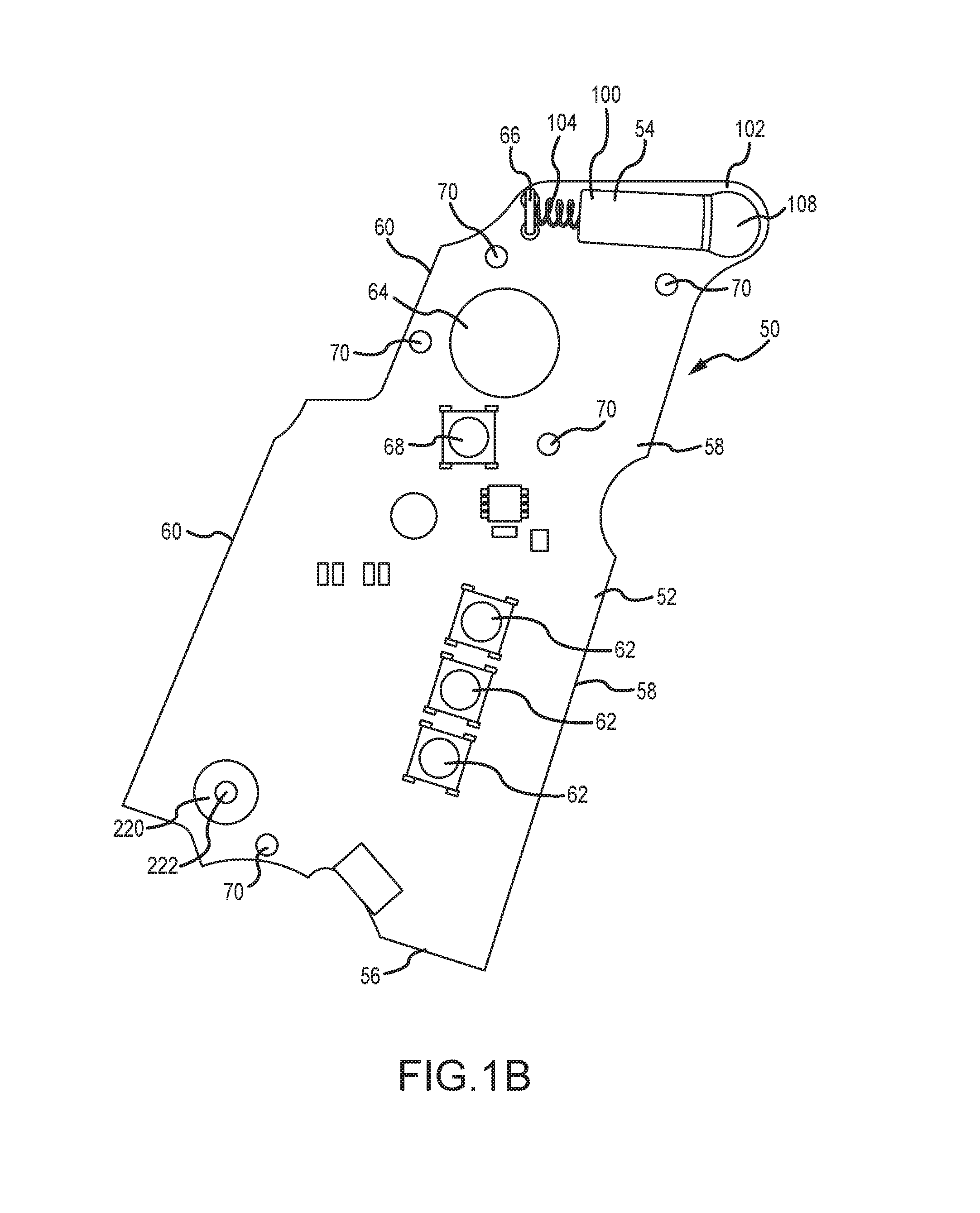
FIG. 1B is a side view of the circuit board of the sighter/trainer of FIG. 1.
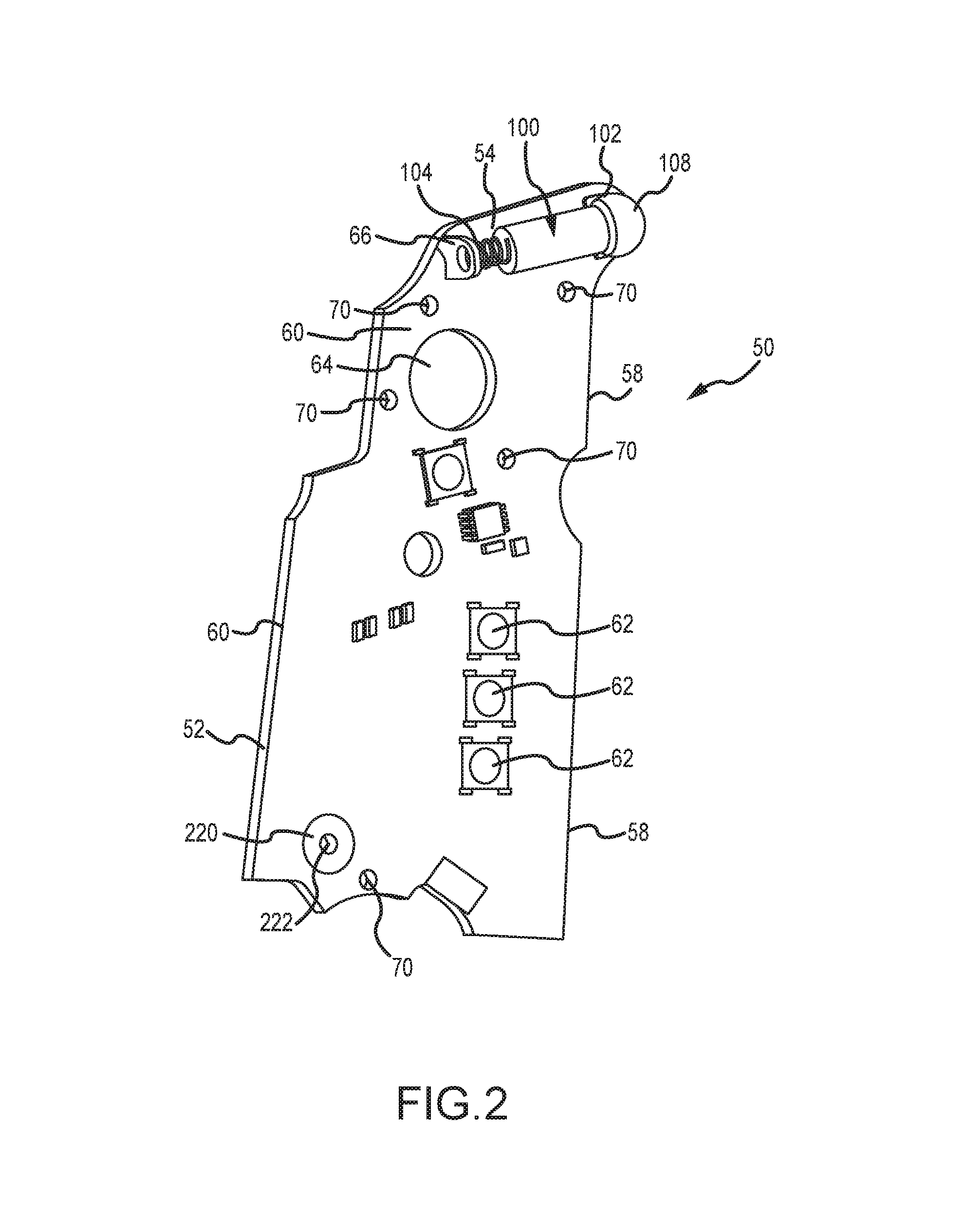
FIG. 2 is a perspective, side view of the sighter/trainer of FIG. 1.
FIG. 3 illustrates exemplary circuitry for the circuit board of FIGS. 1B and 2.
FIG. 4 illustrates exemplary circuitry for the circuit of FIGS. 1B and 2.
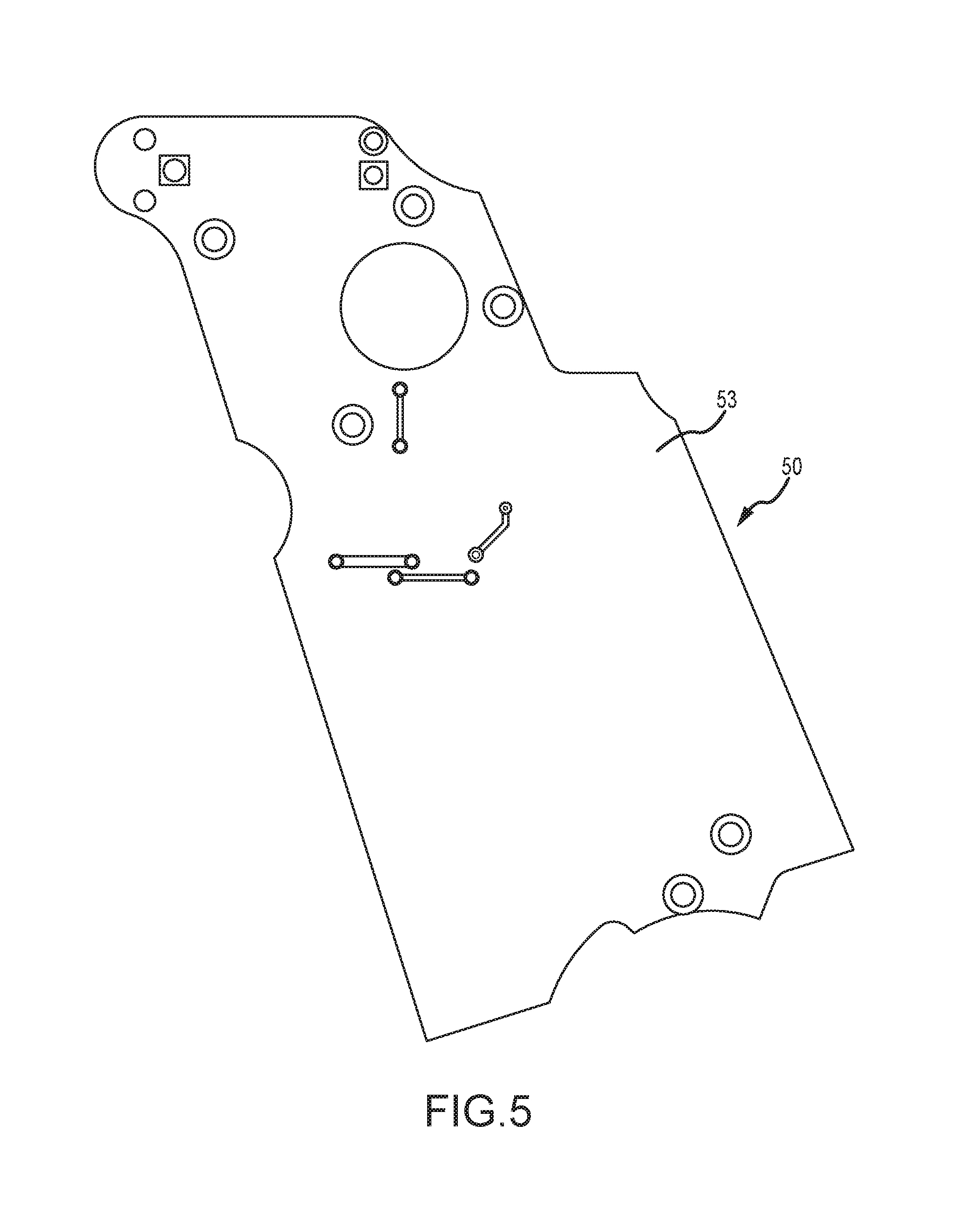
FIG. 5 illustrates exemplary circuitry for the circuit of FIGS. 1B and 2.
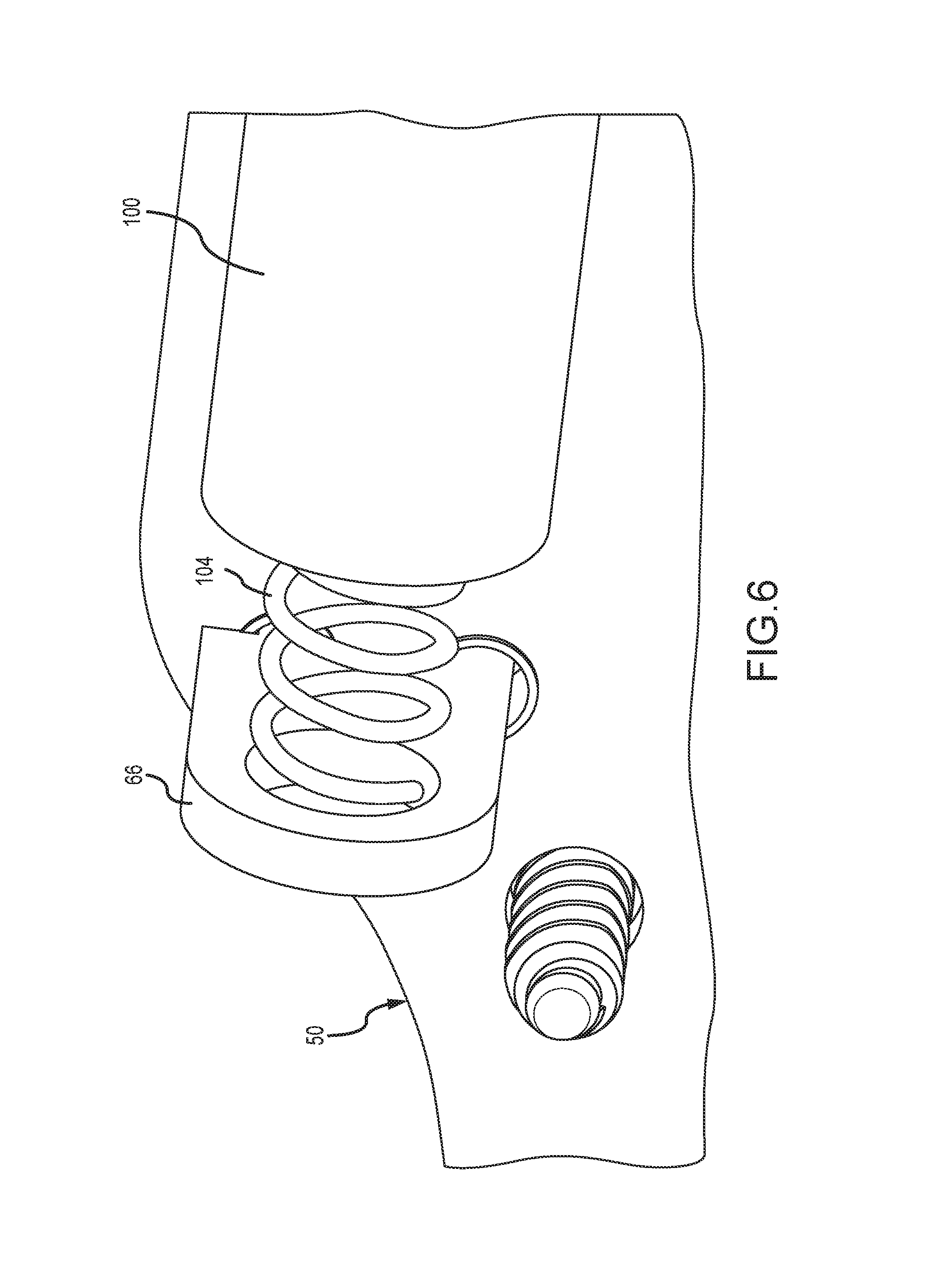
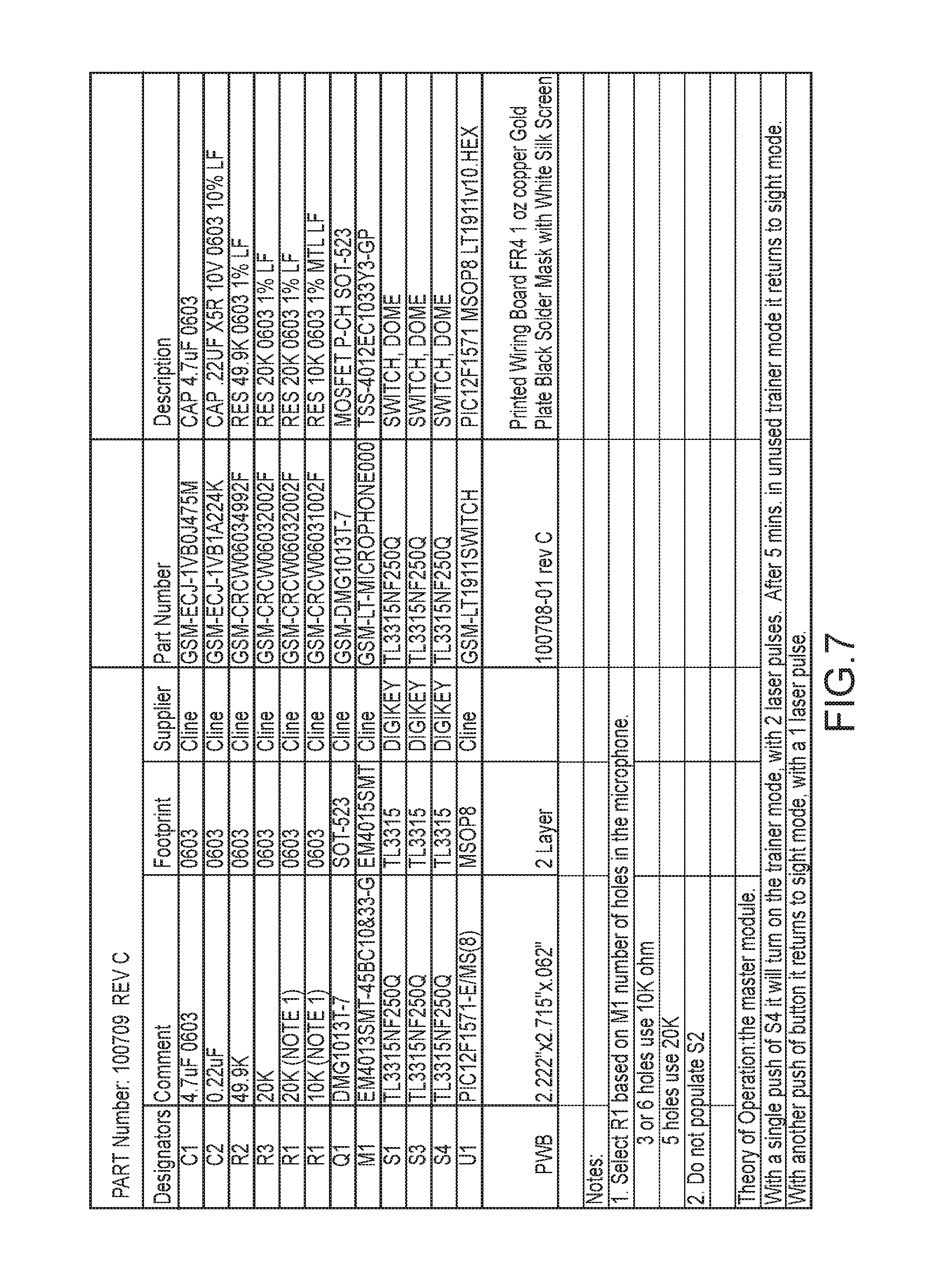
FIG. 6 is a close-up, partial side, perspective view of a laser module and printed circuit board according to the aspects of the disclosure.
FIG. 7 is a list of exemplary components referenced in FIG. 6.
DETAILED DESCRIPTION OF PREFERRED EMBODIMENTS
Turning now to the drawings where the purpose is to describe preferred embodiments of the invention and not to limit same, FIG. 1 is an exploded view of a sighter/trainer 10 according to aspects of the invention. Sighter/trainer 10 has a panel 20, a circuit board 50, and a laser module 100. Sighter/trainer 10 is configured to fit on a pistol handle of a gun as one-half of the grip on the handle. Sighter/trainer 10 may be for any suitable real gun or toy gun, such as a semi-automatic pistol that uses a magazine of bullets, a revolver, a machine pistol, or a rifle (such as an assault-style rifle), which includes a pistol handle. The sighter/trainer 10 may be configured to fit pistol handles of essentially any shape or size.
Panel 20 as shown is configured to be on the right-hand side of the pistol handle (viewed in the direction of fire of the pistol), and it thus forms one side of the grip for the pistol handle. Alternatively, the panel 20 and sighter/trainer 10 could be configured for panel 20 to be on the left-hand side of the pistol handle. This configuration is not shown in the drawings but would be understood by one skilled in the art based on this disclosure.
Panel 20 has an outer surface 22, at least part of which is preferably textured to provide a better grip by a human hand. Panel 20 also has an inner surface 24 that forms a cavity 49 to house various components, as explained below. Panel 20 further includes a top portion 26 with opening 28A formed in top surface 26A, opening 28B formed in side surface 26B, opening 28C in front surface 26C, front edge 30, rear edge 32, bottom 34, and opening 36 through which a battery can be inserted or removed.
Openings 38 and 44 are for receiving fasteners and securing panel 20 to the pistol handle. There is also an indentation 46 for a better fit for this embodiment on the pistol handle and/or to accommodate other fasteners or components of the pistol handle. Opening 40 and button 150 are positioned such that a right-handed shooter can press button 150 with the palm side of the fingers when holding the gun handle, and a left-handed shooter can press button 150 with the fingers of the left hand (which wrap around front edge 30) when holding the pistol handle. A grip configured to be on the left-hand side of a pistol handle would function in a mirror-image manner.
At least one circuit board 50 is configured to be received in cavity 49 formed by side 24 of panel 20. In the embodiment shown, there is a single circuit board 50, but a circuit board according to this disclosure could include multiple sections (i.e., multiple circuit boards) that are electrically connected. For example, there could be two or three separate circuit boards that provide the functionality of the at least one circuit board 50. Circuit board 50 has a first side 52, a second side 53, a top edge 54, a bottom edge 56, a front edge 58, a back edge 60, three compression switches 62 disposed on first side 52, opening 64, bracket 66, compression switch 68, and openings 70 to receive fasteners 160, which pass through openings 70 and are received in screw bosses 51 on second side 24 of panel 20 in order to secure circuit board 50 to panel 20. A negative power connector 220 with opening 222 is in circuit board 50 and receives a fastener 160 through opening 222 which fastens to a screw boss 51. Fastener 160 preferably touches or is connected to circuit board 50 and transfers current to circuit board 50.
Button 150 and switches 62 are positioned for ease of use both by right-handed and left-handed persons. Button 150 is preferably between 3/4'' and 11/4'' in length (at its greatest length, which is measured across dimples 150A) and could have a length at its greatest length of 1/2'', 5/8'', 3/4'', 7/8'', 1'', 11/8'', 11/4'', 13/8'', 11/2'', 15/8'', 13/4'', 17/8'', 2'', or any length between 1/2'' and 2''. The width of switch 62 at its widest point (as measured across any of dimples 150A) is about 1/2'' to 5/8'', but could have a width of 3/8'', 1/2'', 5/8'', 3/4'', 7/8'', 1'', 11/8'', or any width between 3/8'' and 11/8''. The distance from top 26A to top edge 150B of button 150 is about 25%-35% of the distance from top 26A to bottom 34 measured in a straight line, but could be about 20%, 25%, 30%, 35%, 40% or any percentage between 20% and 40%. The distance from side 30 the center of button 150 as measured in a straight line is about 20%-30% of the distance from side 30 to side 32 as measured in a straight line through the center of button 150, but the distance could be 15%, 20%, 25%, 30%, 35%, 40%, or any percentage between 15% and 40%. Button 150 preferably has one or more dimples 150A on its inside surface, wherein each dimple is configured to align with a switch 62 when sighter/trainer 10 is assembled. When the outer side of button 150 is pressed by a user, one or more of dimples 150A depresses one or more switches 62 to activate light source 100 when sighter/trainer 10 is in a first operational mode.
Electrical circuitry 55 (examples of which are shown in FIGS. 3-5) is contained in, disposed on, and/or coupled to circuit board 50, for example on first side 52 of circuit board 50 and optionally in part on second side 53. For example, circuit board 50 may be coupled to and/or electrically interconnect various resistors, capacitors, diodes, inductors, microprocessors, microcontrollers, transistors, integrated circuits, and/or the like in order to implement desired functionality for sighter/trainer 10. FIGS. 40 and 41 of U.S. Application Publication 2016-0161220 entitled "Master Module Light Source and Trainer" also show an exemplary circuit diagram and corresponding part listing for an exemplary sighter/trainer 10.
Switch 68 rests against and can be depressed by button 170, which can be accessed through opening 42 when sighter/trainer 10 is assembled, to change the operational mode of sighter/trainer 10, for example to be either in a first operational mode as a laser sighter or in a second operational mode as a laser trainer. Switches 62 on side 52 of circuit board 50 are positioned against and can be depressed by button grip 150 to contact the circuitry on side 52 and transfer power from battery 180 when sighter/trainer 10 is in its first operational mode, as discussed below.
Battery 180 is preferably a coin cell battery, for example a CR2032 battery, and is received as shown in FIG. 1A. Battery 180 could be any suitable type of battery and is most preferably a lithium 6V coin cell battery, but could have a voltage between 3V and 6V. Battery 180 has a first (positive) terminal on side 182, second (negative) terminal on side 184, and can be inserted and removed from sighter/trainer 10 by removing panel 20 and then removing and/or inserting another battery 180. Light module 100, which as shown is a laser module that projects red laser light (although any suitable laser may be used), fits against laser ball seat tab 102, and has a first end 108 with an opening 108A through which light is emitted, and a spring 104 extending from its second end 104A. Spring 104 is received in opening 67, which is conductive and preferably plated, to provide a conductive path through the circuitry to light module 100.
Positive battery contact 190 has a flange 192, a first side 194, and an aperture 196. Fastener 198 passes through opening 196, through insulating thread insert 200, and is received in a boss in cavity 49 of panel 20. Negative battery contact 210 is electrically conductive, has a stem 212 and a partial loop 214. When sighter/trainer 10 is assembled, a fastener 160 passes through opening 222 and through partial loop 214, and is secured in a boss 51 on panel 20. In this manner, when sighter/trainer 10 is assembled, the second (negative) side 184 of battery 180 touches stem 212 of positive battery contact 210 and partial loop 214 is positioned against positive energy transfer structure 220 to provide a conductive path through screw 160 and facilitate flow of electrical current to circuit board 50.
Similarly, when sighter/trainer 10 is assembled, surface 194 of positive battery contact 190 is positioned against first (positive) side 182 of battery 180 and back surface 199 is positioned against circuit board 50 to provide a conductive path and complete the circuit, thus providing electrical power to circuit board 50 and components electrically connected thereto.
When sighter/trainer 10 is assembled, light module 100 is retained in pocket 27 of upper section 26 of panel 20. A set screw 106 is positioned in opening 28A and can be tightened or loosened to move the first end 108 of light module 100 up and down. Another set screw 106 is positioned in opening 28B and can be tightened or loosened to move first end 108 of light module 100 side to side.
In accordance with aspects of the invention, sighter/trainer 10 is configured to have multiple operational modes. Button 170 can be depressed through opening 44 so that it compresses switch 68, which causes sighter/trainer 10 to be in the first operational mode. When in the first operational mode, laser module 100 is continuously activated when a user presses button grip 150 sufficiently to depress one or more of switches 62, which causes electrical current to flow from battery 180 to light source 100 and cause light source 100 to emit a beam of light. In this manner, sighter/trainer 10 may emit a continuous laser beam for targeting (or sighting) purposes. In this mode, when a switch 62 is not depressed, no electrical current (and/or only minimal electrical current) flows to light source 100 and light source 100 is off.
Button 170 can also be pressed to depress switch 68 and cause sighter/trainer 10 to be in a second operational mode. In the second operational mode, light module 100 is activated for a limited-duration pulse responsive to detection of a particular acoustic signature received at microphone 702 (for example, as seen in FIGS. 36 and 39 of U.S. Patent Application Publication No. 2016-0161220). In this manner, sighter/trainer 10 may be utilized to emit a pulse from laser module 100 only after detection of a sound, such as the sound of operation of a firing pin.
Button 170 of sighter/trainer 10 may be pressed to depress switch 68 to change the operational mode of sighter/trainer 10 back and forth from the first operational mode to the second operational mode, depending on what the user desires. Sighter/trainer 10 may also have a third operational mode in which sighter/trainer 10 is off and electrical current does not flow to light source 100 even if one or more switches 62 are depressed. In that case, the user can press switch 170 to go from, for example, the first operational mode, then to the second operational mode, to the third operational mode, and then back to the first operational mode.
Sighter/trainer 10 may utilize a microprocessor 700 configured to control operation of sighter/trainer 10, for example a PIC12F1571 microprocessor offered by MicroChip Corporation (Chandler, Ariz.). However, any suitable microprocessor 700 may be used. Microprocessor 700 is responsible for governing operation of sighter/trainer 10, including activation and deactivation of light source 100, changing sighter/trainer 10 from a first operational mode to a second operational mode responsive to switch or button inputs, and so forth. Microprocessor 700 may accommodate the control inputs from microphone 702 as well as switch(es) 68, as well as other control inputs and signal outputs utilized in sighter/trainer 10. Microprocessor 700, microphone 702, light source 100, and other components of sighter/trainer 10 may be mechanically and electrically coupled to one another via circuit board 50 and the traces thereon and/or therein, for example as illustrated in FIGS. 3-5 herein (and/or in FIGS. 37, 38, 40, 41, 43, and 44 of U.S. Patent Application Publication No. 2016-0161220). Additionally, various connective wires may be utilized, as needed, in order to provide desired electrical connections within sighter/trainer 10.
Thus, in accordance with these aspects a single sighter/trainer 10 may be used as a targeting laser using live ammunition, yet also suitable for training without live ammunition. Additionally, sighter/trainer 10 is configured for ambidextrous operation, being suitable for use by both right-handed and left-handed shooters without modification.
Some specific, nonlimiting examples of the invention follow:
1. A sighter/trainer device configured to be attached to the pistol handle of a gun, wherein the grip comprises:
(a) a panel; (b) at least one circuit board configured with circuitry having a first operational mode and a second operational mode; (c) a laser in communication with the circuit board; (d) a power source in communication with the circuit board; and (e) a switch in communication with the circuit board, the switch being moveable to change the operational mode of the circuitry. 2. The sighter/trainer device of example 1 that includes a second button that can be depressed to cause electrical current to be delivered to the laser when the at least one circuit board is in its second operational mode. 3. The sighter/trainer device of example 2, wherein the second button has a length of 1'' or more and a width of 1/2'' or more. 4. The sighter/trainer device of example 2, wherein the second button has a height of 11/4'' to 3''. 5. The sighter/trainer device of example 2, wherein the second button presses against a plurality of switches on the circuit board. 6. The sighter/trainer device of example 2, wherein the second button presses against three switches on the circuit board. 7. The sighter/trainer device of example 2, wherein the panel has a front edge and the second button is positioned no more than 3/4'' behind the front edge. 8. The sighter/trainer device of example 2, wherein the panel has a bottom and the second button is positioned at least 2'' from the bottom. 9. The sighter/trainer device of example 2, wherein the panel has a height and the second button is positioned entirely in the top half of the height. 10. The sighter/trainer device of example 2, wherein the panel has a width and the second button is positioned entirely in the front half of the width. 11. The sighter/trainer device of example 6, wherein the through bolt hole is plated. 12. The sighter/trainer device of example 7 or 8, wherein a spring is retained in the through bolt hole. 13. The sighter/trainer device of example 8, wherein the spring is soldered in the through bolt hole. 14. The sighter/trainer device of example 8 or 9, wherein the spring biases the light source away from the spring. 15. The sighter/trainer device of any of examples 8-10, wherein the spring provides a negative electrical contact for the light source. 16. The sighter/trainer device of example 1, wherein electrical current from the power source travels through the first circuit board to reach the light source. 17. The sighter/trainer device of example 15, wherein electrical current from the power source travels through the first circuit board and second circuit board to reach the light source. 18. The sighter/trainer device of any of examples 1-16, wherein the light source is a laser. 19. The sighter/trainer device of any of examples 1-18, wherein the power source is in a grip that is connected to the first circuit board. 20. The sighter/trainer device of any of examples 1-19, wherein the power source is one or more batteries. 21. The sighter/trainer device of example 20, wherein each adjustment device is a set screw. 22. The sighter/trainer device of example 20 or 21, wherein one of the adjustment devices moves the light source from side to side and the other adjustment device moves the light source up and down. 23. The sighter/trainer device of any of examples 1-22 that is configured to cause the light source to operate in any of the following modes: stay constantly on, stay constantly off, or turn from the on position to the off position after a predetermined period of time. 24. The sighter/trainer device of any of examples 1-24 that includes one or more switches to change the mode of operation of the light source. 25. The sighter/trainer device of example 25, wherein the one or more switches is on the first circuit board. 26. The sighter/trainer device of any of examples 1-25, wherein the power source is one battery. 27. The sighter/trainer device of any of examples 1-26, wherein the power source is enclosed in a panel cavity. 28. The sighter/trainer device of any of examples 1-27, wherein the power source is surrounded by an insulating sleeve. 29. The sighter/trainer device of any of examples 1-28, wherein the grip includes a cap on its end for removing and replacing the power source. 30. The sighter/trainer device of any of examples 1-29, wherein the light source has a first end through which light is emitted and the first end is retained partially in a module cushion ball.
Having thus described preferred embodiments of the invention, other variations and embodiments that do not depart from the spirit of the invention will become apparent to those skilled in the art. The scope of the present invention is thus not limited to any particular embodiment, but is instead set forth in the appended claims and the legal equivalents thereof. Unless expressly stated in the written description or claims, the steps of any method recited in the claims may be performed in any order capable of yielding the desired result.
* * * * *
References
-
dennyducet.blogspot.com/2015/06/the-arsenal-strike-one-innovative.html
-
airgunexpress.com/Accessories/referencingvariousleveldevices
-
secure.armorholdings.com/b-square/smarthtml/about.htmlreferencingbackground
-
-
battenfeldtechnologies.com/113088.htmlreferencingaleveldevice
-
-
blackanddecker.com/laserline/lasers.aspxreferencingBlack&Decker
-
laserlevel.co.uk/newsite.index.aspreferencingthelaserdevicesavailable
D00000
D00001
D00002
D00003
D00004
D00005
D00006
D00007
D00008
D00009
XML
uspto.report is an independent third-party trademark research tool that is not affiliated, endorsed, or sponsored by the United States Patent and Trademark Office (USPTO) or any other governmental organization. The information provided by uspto.report is based on publicly available data at the time of writing and is intended for informational purposes only.
While we strive to provide accurate and up-to-date information, we do not guarantee the accuracy, completeness, reliability, or suitability of the information displayed on this site. The use of this site is at your own risk. Any reliance you place on such information is therefore strictly at your own risk.
All official trademark data, including owner information, should be verified by visiting the official USPTO website at www.uspto.gov. This site is not intended to replace professional legal advice and should not be used as a substitute for consulting with a legal professional who is knowledgeable about trademark law.