Pipe tradesman's ladder and method
Astor , et al. Feb
U.S. patent number 10,208,538 [Application Number 11/416,967] was granted by the patent office on 2019-02-19 for pipe tradesman's ladder and method. This patent grant is currently assigned to Werner Co.. The grantee listed for this patent is Kyle G. Astor, James J. Grebinoski, Brett Latimer. Invention is credited to Kyle G. Astor, James J. Grebinoski, Brett Latimer.


| United States Patent | 10,208,538 |
| Astor , et al. | February 19, 2019 |
Pipe tradesman's ladder and method
Abstract
A stepladder includes a pipe/tube holder attached to the rear side for holding pipe and/or a strap bender attached to a rail or a rear rung through which a strap is inserted to be bent, and/or a utility hook attached to the rear side. A method for cutting a pipe. A method for using a tool. A method for bending a strap.
| Inventors: | Astor; Kyle G. (Meadville, PA), Grebinoski; James J. (Mercer, PA), Latimer; Brett (New Castle, PA) | ||||||||||
|---|---|---|---|---|---|---|---|---|---|---|---|
| Applicant: |
|
||||||||||
| Assignee: | Werner Co. (Greenville,
PA) |
||||||||||
| Family ID: | 46325449 | ||||||||||
| Appl. No.: | 11/416,967 | ||||||||||
| Filed: | May 3, 2006 |
Prior Publication Data
| Document Identifier | Publication Date | |
|---|---|---|
| US 20070193829 A1 | Aug 23, 2007 | |
Related U.S. Patent Documents
| Application Number | Filing Date | Patent Number | Issue Date | ||
|---|---|---|---|---|---|
| 11358626 | Feb 21, 2006 | 7886872 | |||
| Current U.S. Class: | 1/1 |
| Current CPC Class: | E06C 1/18 (20130101); E06C 7/14 (20130101) |
| Current International Class: | E06C 7/14 (20060101); E06C 1/18 (20060101) |
| Field of Search: | ;182/129 |
References Cited [Referenced By]
U.S. Patent Documents
| 529871 | November 1894 | miner |
| 868694 | October 1907 | parks |
| 998112 | July 1911 | murray |
| 1672717 | June 1928 | Gentner |
| 1794700 | March 1931 | McCaskey |
| 2088895 | August 1937 | Connell |
| 2166255 | July 1939 | Ligon |
| 2398617 | April 1946 | Casey |
| 2801886 | August 1957 | Peterson |
| 2871067 | January 1959 | Brogdon |
| 3363864 | January 1968 | Olgreen |
| 3477679 | November 1969 | Lovitz |
| 3511338 | May 1970 | Chapman |
| 3693754 | September 1972 | Butler |
| 3698511 | October 1972 | Dohan |
| 3887034 | June 1975 | Sawatzky |
| 3901064 | August 1975 | Jacobson |
| 3915189 | October 1975 | Holbrook et al. |
| 4079814 | March 1978 | Larson |
| D248777 | August 1978 | Spencer |
| 4111027 | September 1978 | Bottomley |
| 4167865 | September 1979 | Powell |
| 4176580 | December 1979 | Gallegos |
| 4261435 | April 1981 | Winter |
| 4311209 | January 1982 | Primerano |
| 4318454 | March 1982 | Johnson |
| 4355700 | October 1982 | Matthews et al. |
| 4407478 | October 1983 | Hodges |
| 4424752 | January 1984 | Aberg |
| 4488424 | December 1984 | McBride |
| 4609167 | September 1986 | Dean |
| 4630709 | December 1986 | Taylor |
| 4653608 | March 1987 | Casada |
| 4653713 | March 1987 | Hamilton |
| 4714162 | December 1987 | Harrison |
| 4759162 | July 1988 | Wyse |
| 4815684 | March 1989 | Kellstadt |
| 4858869 | August 1989 | Stang |
| 4862994 | September 1989 | Hughes, Sr. |
| 4919230 | April 1990 | Langer et al. |
| 4995578 | February 1991 | Monheim |
| 5035389 | July 1991 | Wang |
| 5052581 | October 1991 | Christ et al. |
| 5100086 | March 1992 | Rinderer |
| 5150938 | September 1992 | Gans |
| 5158023 | October 1992 | Allen |
| D334240 | March 1993 | Huffine |
| 5240214 | August 1993 | Birnbaum et al. |
| 5259480 | November 1993 | Bartnicki et al. |
| 5263550 | November 1993 | Jines |
| 5351730 | October 1994 | Lewellen et al. |
| 5358070 | October 1994 | Bartnicki et al. |
| 5370263 | December 1994 | Brown |
| 5419409 | May 1995 | Corulla |
| 5429205 | July 1995 | Collins |
| 5433416 | July 1995 | Johnson |
| 5460241 | October 1995 | LaBelle |
| 5503245 | April 1996 | Etesam |
| 5544718 | August 1996 | Schumacher |
| 5547080 | August 1996 | Klimas |
| D374937 | October 1996 | Salas |
| 5573081 | November 1996 | Bartnicki et al. |
| 5584357 | December 1996 | Gugel et al. |
| 5622278 | April 1997 | Fries et al. |
| 5628381 | May 1997 | Markovich et al. |
| 5653459 | August 1997 | Murphy |
| 5673885 | October 1997 | Pham |
| 5740883 | April 1998 | Trank |
| 5782314 | July 1998 | Zeitler |
| 5791607 | August 1998 | Thibault |
| 5797571 | August 1998 | Brophy |
| 5899420 | May 1999 | Gerardi |
| 5924615 | July 1999 | McGarrah |
| 5992564 | November 1999 | Kirkpatrick |
| 6024192 | February 2000 | Griffin |
| D422717 | April 2000 | Bartnicki et al. |
| 6085867 | July 2000 | Daniel et al. |
| 6089351 | July 2000 | Ahl |
| 6089383 | July 2000 | Heneveld |
| 6367744 | April 2002 | Ebersole |
| 6401862 | June 2002 | Caron |
| 6412601 | July 2002 | Schmidt |
| 6443260 | September 2002 | Katz et al. |
| 6454050 | September 2002 | Gibson et al. |
| 6467577 | October 2002 | Charlebois, Jr. |
| 6481583 | November 2002 | Black et al. |
| 6502664 | January 2003 | Peaker, Sr. |
| 6585204 | July 2003 | Haertzen |
| 6591941 | July 2003 | Mannie |
| 6810995 | November 2004 | Warford |
| D500145 | December 2004 | Cromberg |
| 6880794 | April 2005 | Kahn |
| 6912886 | July 2005 | Maes |
| 6942063 | September 2005 | Huett, Jr. |
| 7063187 | June 2006 | Lavigne |
| 7077238 | July 2006 | Butler |
| D530025 | October 2006 | Patton et al. |
| D531322 | October 2006 | Patton et al. |
| 7143629 | December 2006 | Chiu |
| 7159694 | January 2007 | Gibson |
| D538634 | March 2007 | King |
| D541433 | April 2007 | Wise |
| D557093 | December 2007 | Holt |
| 7341259 | March 2008 | Slabich et al. |
| 7500335 | March 2009 | Kjose |
| 7836743 | November 2010 | McCoy |
| 7850177 | December 2010 | Gilhuly |
| 7975856 | July 2011 | Gilpatrick |
| 8016078 | September 2011 | Astor |
| 2002/0017430 | February 2002 | Rosko |
| 2002/0185576 | December 2002 | Harper |
| 2003/0196855 | October 2003 | Kvam |
| 2003/0213646 | November 2003 | Gallion |
| 2003/0230452 | December 2003 | Campagna |
| 2005/0150724 | July 2005 | Snider et al. |
| 2007/0084669 | April 2007 | Campagna et al. |
| 2007/0193829 | August 2007 | Astor |
| 2008/0142300 | June 2008 | Roberge |
| 2008/0202391 | August 2008 | Pisano |
| 2009/0078504 | March 2009 | Astor |
| 2010/0326771 | December 2010 | Kreller |
| 2011/0198153 | August 2011 | Dufour et al. |
| 2002227575 | Aug 2002 | JP | |||
| 2002227575 | Aug 2002 | JP | |||
Assistant Examiner: Bradford; Candace L
Attorney, Agent or Firm: Schwartz; Ansel M.
Parent Case Text
This application is a continuation-in-part of copending application Ser. No. 11/358,626 filed on Feb. 21, 2006.
Claims
What is claimed is:
1. A stepladder comprising: a front side, said front side comprised of a first front rail, and a second front rail in parallel with the first front rail and in spaced relationship therewith, said front side also comprised of a plurality of front rungs, each front rung being connected to the first front rail and the second front rail and perpendicular thereto, each front rung in parallel and in spaced relationship with the other front rungs; a rear side, said rear side comprised of a first rear rail and a second rear rail in parallel with the first rear rail and in spaced relationship therewith, said rear side also comprised of a plurality of rear rungs, each rear rung connected to the first rear rail and the second rear rail and perpendicular thereto, each rear rung in parallel and in spaced relationship with the other rear rungs; a top, said front side and rear side fixedly attached to the top such that the front side and rear side can be folded together into a closed position where the front side and rear side are essentially in parallel or opened about the top into an operational position where the front side and rear side are at an angular relationship and a workman can climb to a desired rung and perform whatever work is desired; and a pipe or tube holder rotatably connected to and disposed between the first rear rail and the second rear rail of the rear side which holds a tube or a pipe, the pipe or tube holder includes a first hook rotatably connected to the first rear rail and a second hook rotatably connected to the second rear rail, each hook having a C shape which conforms with a circular cross-sectional shape of the tube or pipe, the tube or pipe disposed in the C shape of each hook, and a stamping to which the first and second hooks are connected in alignment with each other, the stamping attached at the stamping's ends to a bottom of the C shape of the first and second hooks and extending therebetween, the stamping separate and apart from the rear side, the stamping attached to the first and second hooks; by rotating the stamping, the first and second hooks move in unison with the stamping between a retracted position and an open position, the first and second hooks hold a first pipe in parallel to the rear rungs when the first pipe is disposed on the first and second hooks, the stamping includes a scallop portion upon which a second pipe is held and rests perpendicular to the first pipe and contacts the first pipe when the second pipe is resting on the scallop portion so joints or fittings between the first pipe and second pipe can be created and held while the first pipe is held by the first and second hooks, the stamping having a flat plate, the scallop portion formed in the plate and having a circular slot extending down from a top edge of the plate which receives and conforms with a circular cross-sectional shape of the second pipe, the first and second hooks extending perpendicularly from the plate, the pipe or tube holder disposed below a rung of the rear side, in the retracted position, the stamping extending behind and in spaced relation with the rear side, in the open position, the stamping extending in front of and in spaced relationship with the rear side so the pipe is held by the first and second hooks in front of the rear side and a spring which automatically retracts the pipe or tube holder to the retracted position from the open position when the first pipe is moved from the first and second hooks, the first pipe maintains the pipe or tube holder in the open position when the first pipe is disposed on the first and second hooks which prevents the pipe or tube holder from retracting.
2. A stepladder as described in claim 1 wherein the pipe or tube holder includes a first side shield and a second side shield fixedly attached to the first rear rail and the second rear rail respectively, to protect the respective rear rail, each rail shield covering the respective rails web and flange outer surface.
3. A stepladder as described in claim 2 wherein the pipe or tube holder includes a first mounting bracket connected to the first rear rail and the first hook, and a second mounting bracket connected to the second rear rail and the second hook.
4. A stepladder comprising: a front side, said front side comprised of a first front rail, and a second front rail in parallel with the first front rail and in spaced relationship therewith, said front side also comprised of a plurality of front rungs, each front rung being connected to the first front rail and the second front rail and perpendicular thereto, each front rung in parallel and in spaced relationship with the other front rungs; a rear side, said rear side comprised of a first rear rail and a second rear rail in parallel with the first rear rail and in spaced relationship therewith, said rear side also comprised of a plurality of rear rungs, each rear rung connected to the first rear rail and the second rear rail and perpendicular thereto, each rear rung in parallel and in spaced relationship with the other rear rungs; a top, said front side and rear side fixedly attached to the top such that the front side and rear side can be folded together into a closed position where the front side and rear side are essentially in parallel or opened about the top into an operational position where the front side and rear side are at an angular relationship and a workman can climb to a desired rung and perform whatever work is desired, the front side and the rear side and the top together defining a frame; a pipe or tube holder fixedly attached to the first rear rail and the second rear rail of the rear side which holds a tube or a pipe, the pipe or tube holder includes a first hook rotatably connected to the first rear rail and a second hook rotatably connected to the second rear rail, each hook having a C shape which conforms with a circular cross-sectional shape of the tube or pipe, the tube or pipe disposed in the C shape of each hook, and a stamping to which the first and second hooks are connected in alignment with each other, the stamping separate and apart from the rear side, the stamping attached to the first and second hooks, the stamping attached at the stamping's ends to a bottom of the C shape of the first and second hooks and extending therebetween; by rotating the stamping, the first and second hooks move in unison with the stamping between a retracted position and an open position, the first and second hooks hold a first pipe in parallel to the rear rungs when the first pipe is disposed on the first and second hooks, the stamping includes a scallop portion upon which a second pipe is held and rests perpendicular to the first pipe and contacts the first pipe when the second pipe is resting on the scallop portion so joints or fittings between the first pipe and second pipe can be created and held while the first pipe is held by the first and second hooks, the stamping having a flat plate, the scallop portion formed in the plate and having a circular slot extending down from a top edge of the plate which receives and conforms with a circular cross-sectional shape of the second pipe, the first and second hooks extending perpendicularly from the plate, and a spring which automatically retracts the pipe or tube holder to the retracted position from the open position when the first pipe is moved from the first and second hooks, the first pipe maintains the pipe or tube holder in the open position when the first pipe is disposed on the first and second hooks which prevents the pipe or tube holder from retracting; a metal strap bender made of metal attached to a rail or a rear rung, the strap bender having a rectangular shaped opening through which a metal strap is inserted to be bent, the bender configured to be used to bend the metal strap 90.degree.; and a utility hook fixedly attached to either the front or rear side and positioned between the front side and rear side and inside the frame when the front and rear sides are in the operational position so as not to create a tipping hazard.
Description
CROSS-REFERENCE
This application is related to contemporaneously filed U.S. patent application having Ser. No. 11/416,961, titled "Pipe Tradesman's Ladder Top and Method", by Kyle G. Astor, incorporated by reference herein.
FIELD OF THE INVENTION
The present invention is related to a pipe tradesman ladder. More specifically, the present invention is related to a pipe tradesman ladder preferably having a pipe/tube holder, a utility hook and a strap bender.
BACKGROUND OF THE INVENTION
For years, stepladders have been designed for the general construction and painting professionals needs. Bauer Corporation provides a ladder vise, U.S. Pat. No. 4,318,454 that attaches to a stepladder to hold materials securely. This vise requires the user to first operate the vise on one side and place the conduit in and then open the opposite side and place the conduit in to hold it firmly. This holder is a spring loaded sliding design that will hold a variety of materials.
For years, stepladders have been designed for the general construction and painting professionals needs. The new Werner Pipe Trade ladder is designed for the specific needs of the Pipe of piping tubing, and slots and hooks for tool storage. These added features help make the user's job safer and more efficient.
Bauer ladders developed and patented a Ladder Vise in 1981, U.S. Pat. No. 4,318,454. Their design requires the user to first operate the vise on one side and place the pipe/tube in and then open the opposite side and place the other end of the pipe/tube in to hold it firmly. Their holder is a spring loaded sliding design that will hold a variety of materials.
SUMMARY OF THE INVENTION
The present invention pertains to a stepladder. The stepladder comprises a front side. The front side comprised of a first front rail, and a second front rail in parallel with the first front rail and in spaced relationship therewith. The front side also comprised of a plurality of front rungs or steps. Each front rung being connected to the first front rail and the second front rail and perpendicular thereto. Each front rung in parallel and in spaced relationship with the other front rungs. The stepladder comprises a rear side. The rear side comprised of a first rear rail and a second rear rail in parallel with the first rear rail and in spaced relationship therewith. The rear side also comprised of a plurality of rear rungs. Each rear rung or horizontal is connected to the first rear rail and the second rear rail and perpendicular thereto. Each rear rung in parallel and in spaced relationship with the other rear rungs. The stepladder comprises a top. The front side and rear side fixedly attached to the top such that the front side and rear side can be folded together into a closed position where the front side and rear side are essentially in parallel or opened about the top into an operational position where the front side and rear side are at an angular relationship and a workman can climb to a desired rung and perform whatever work is desired. The stepladder comprises a pipe/tube holder attached to the rear side for holding pipe.
The present invention pertains to a stepladder. The stepladder comprises a front side. The front side comprised of a first front rail, and a second front rail in parallel with the first front rail and in spaced relationship therewith. The front side also comprised of a plurality of front rungs. Each front rung being connected to the first front rail and the second front rail and perpendicular thereto. Each front rung in parallel and in spaced relationship with the other front rungs. The stepladder comprises a rear side. The rear side comprised of a first rear rail and a second rear rail in parallel with the first rear rail and in spaced relationship therewith. The rear side also comprised of a plurality of rear rungs. Each rear rung connected to the first rear rail and the second rear rail and perpendicular thereto. Each rear rung in parallel and in spaced relationship with the other rear rungs. The stepladder comprises a top. The front side and rear side fixedly attached to the top such that the front side and rear side can be folded together into a closed position where the front side and rear side are essentially in parallel or opened about the top into an operational position where the front side and rear side are at an angular relationship and a workman can climb to a desired rung and perform whatever work is desired. The stepladder comprises a utility hook attached to the rear side.
The present invention pertains to a stepladder. The stepladder comprises a front side. The front side comprised of a first front rail, and a second front rail in parallel with the first front rail and in spaced relationship therewith. The front side also comprised of a plurality of front rungs. Each front rung being connected to the first front rail and the second front rail and perpendicular thereto. Each front rung in parallel and in spaced relationship with the other front rungs. The stepladder comprises a rear side. The rear side comprised of a first rear rail and a second rear rail in parallel with the first rear rail and in spaced relationship therewith. The rear side also comprised of a plurality of rear rungs. Each rear rung connected to the first rear rail and the second rear rail and perpendicular thereto. Each rear rung in parallel and in spaced relationship with the other rear rungs. The stepladder comprises a top. The front side and rear side fixedly attached to the top such that the front side and rear side can be folded together into a closed position where the front side and rear side are essentially in parallel or opened about the top into an operational position where the front side and rear side are at an angular relationship and a workman can climb to a desired rung and perform whatever work is desired. The stepladder comprises a strap bender attached to a rail or a rear rung through which a strap is inserted to be bent.
The present invention pertains to a stepladder. The stepladder comprises a front side. The front side comprised of a first front rail, and a second front rail in parallel with the first front rail and in spaced relationship therewith. The front side also comprised of a plurality of front rungs. Each front rung being connected to the first front rail and the second front rail and perpendicular thereto. Each front rung in parallel and in spaced relationship with the other front rungs. The stepladder comprises a rear side. The rear side comprised of a first rear rail and a second rear rail in parallel with the first rear rail and in spaced relationship therewith. The rear side also comprised of a plurality of rear rungs. Each rear rung connected to the first rear rail and the second rear rail and perpendicular thereto. Each rear rung in parallel and in spaced relationship with the other rear rungs. The stepladder comprises a top. The front side and rear side fixedly attached to the top such that the front side and rear side can be folded together into a closed position where the front side and rear side are essentially in parallel or opened about the top into an operational position where the front side and rear side are at an angular relationship and a workman can climb to a desired rung and perform whatever work is desired. The stepladder comprises a pipe/tube holder attached to the rear side for holding pipe. The stepladder comprises a strap bender attached to a rail or a rear rung through which a strap is inserted to be bent. The stepladder comprises a utility hook attached to the rear side.
The present invention pertains to a method for cutting a pipe. The method comprises the steps of moving a pipe/tube holder of a rear side of a stepladder into an open position. There is the step of placing the pipe on the pipe/tube holder. There is the step of cutting the pipe while it is on the pipe/tube holder.
The present invention pertains to a method for using a tool. The method comprises the steps of taking the tool off of a utility hook attached in proximity to a center of a rung of a rear side of a stepladder. There is the step of using the tool on an object.
The present invention pertains to a method for bending a strap. The method comprises the steps of placing a first end of a strap into an opening of a strap bender on a rail or rear rung of a stepladder. There is the step of bending the strap while its first end is in the strap bender.
BRIEF DESCRIPTION OF THE DRAWINGS
In the accompanying drawings, the preferred embodiment of the invention and preferred methods of practicing the invention are illustrated in which:
FIG. 1 is a schematic representation of a stepladder of the present invention.
FIG. 2 is a schematic representation of a pipe/tube holder with pipe.
FIG. 3 is a schematic representation of a pipe/tube holder in an open position.
FIG. 4 is a schematic representation of the ladder with the utility hook.
FIG. 5 is a schematic representation of the strap bender.
FIG. 6 is a schematic representation of the pipe/tube holder.
FIG. 7 is a schematic representation of the pipe/tube holder.
FIG. 8 is a schematic representation of an alternative embodiment of the pipe/tube holder.
FIG. 9 is a schematic representation of an alternative embodiment of the pipe/tube holder in a retracted position.
FIG. 10 is a schematic representation of an alternative embodiment of the pipe/tube holder in an open position.
DETAILED DESCRIPTION
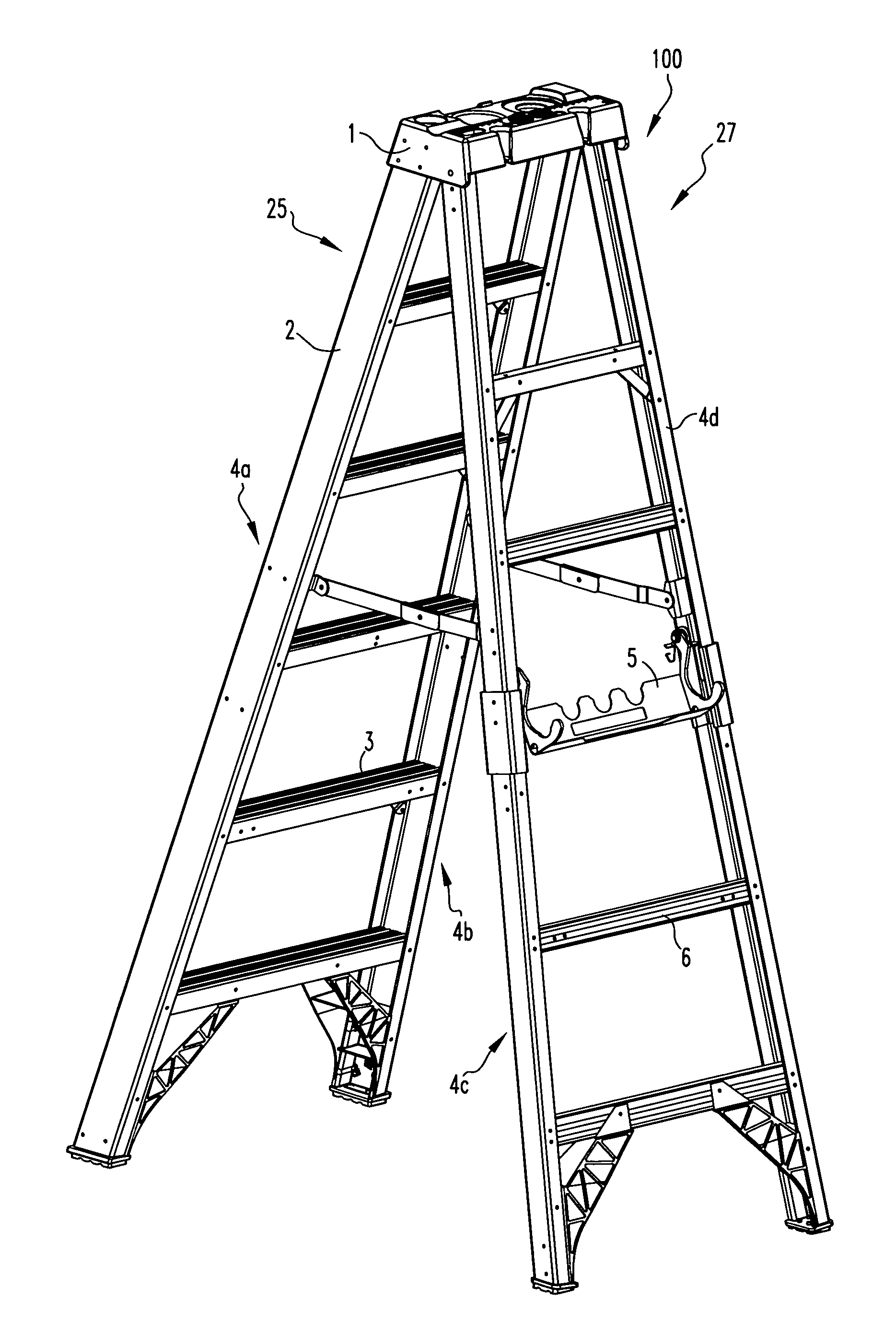
Referring now to the drawings wherein like reference numerals refer to similar or identical parts throughout the several views, and more specifically to FIG. 1 thereof, there is shown a stepladder 100. The stepladder 100 comprises a front side 25. The front side 25 is comprised of a first front rail 4a, and a second front rail 4b in parallel with the first front rail 4a and in spaced relationship therewith. The front side 25 is also comprised of a plurality of front rungs. Each front rung being connected to the first front rail 4a and the second front rail 4b and perpendicular thereto. Each front rung in parallel and in spaced relationship with the other front rungs. The stepladder 100 comprises a rear side 27. The rear side 27 comprised of a first rear rail 4c and a second rear rail 4d in parallel with the first rear rail 4c and in spaced relationship therewith. The rear side 27 also comprised of a plurality of rear rungs. Each rear rung connected to the first rear rail 4c and the second rear rail 4d and perpendicular thereto. Each rear rung in parallel and in spaced relationship with the other rear rungs. The stepladder 100 comprises a top 1. The front side 25 and rear side 27 fixedly attached to the top 1 such that the front side 25 and rear side 27 can be folded together into a closed position where the front side 25 and rear side 27 are essentially in parallel or opened about the top 1 into an operational position where the front side 25 and rear side 27 are at an angular relationship and a workman can climb to a desired rung and perform whatever work is desired. The stepladder 100 comprises a pipe/tube holder 5 attached to the rear side 27 for holding pipe.
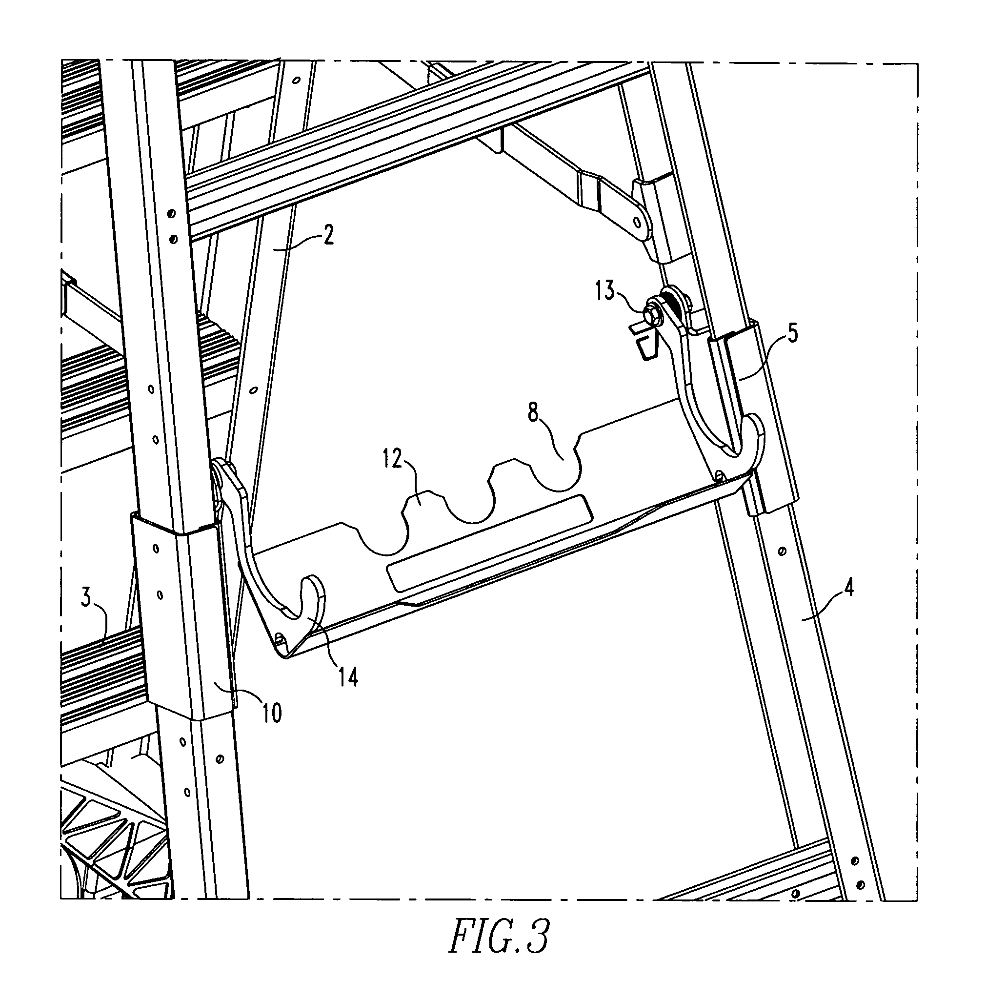
Preferably, the pipe/tube holder 5 includes a first side shield and a second side shield attached to the first rear rail 4c and the second rear rail 4d respectively, to protect the respective rear rail. The pipe/tube holder 5 preferably includes a first hook and a second hook, and a stamping 12 to which the first and second hooks are connected in alignment with each other; by moving the stamping 12, the first and second hooks move in unison with the stamping 12 between a retracted position and an open position. Preferably, the pipe/tube holder 5 includes a first mounting bracket connected to the first rear rail 4c and the first hook, and a second mounting bracket connected to the second rear rail 4d and the second hook. The stamping 12 preferably includes a scallop portion 8 upon which pipe can rest.
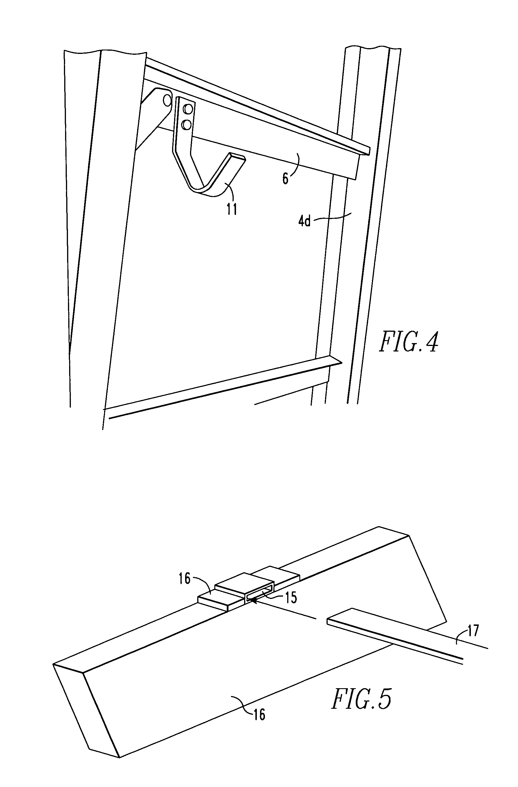
The present invention pertains to a stepladder 100. The stepladder 100 comprises a front side 25. The front side 25 comprised of a first front rail 4a, and a second front rail 4b in parallel with the first front rail 4a and in spaced relationship therewith. The front side 25 also comprised of a plurality of front rungs. Each front rung being connected to the first front rail 4a and the second front rail 4b and perpendicular thereto. Each front rung in parallel and in spaced relationship with the other front rungs. The stepladder 100 comprises a rear side 27. The rear side 27 comprised of a first rear rail 4c and a second rear rail 4d in parallel with the first rear rail 4c and in spaced relationship therewith. The rear side 27 also comprised of a plurality of rear rungs. Each rear rung connected to the first rear rail 4c and the second rear rail 4d and perpendicular thereto. Each rear rung in parallel and in spaced relationship with the other rear rungs. The stepladder 100 comprises a top 1. The front side 25 and rear side 27 fixedly attached to the top 1 such that the front side 25 and rear side 27 can be folded together into a closed position where the front side 25 and rear side 27 are essentially in parallel or opened about the top 1 into an operational position where the front side 25 and rear side 27 are at an angular relationship and a workman can climb to a desired rung and perform whatever work is desired. The stepladder 100 comprises a utility hook 11 attached to the rear side 27.
Preferably, the utility hook 11 is attached to the rear in proximity to the center of a rung of the rear side 27.
The present invention pertains to a stepladder 100. The stepladder 100 comprises a front side 25. The front side 25 comprised of a first front rail 4a, and a second front rail 4b in parallel with the first front rail 4a and in spaced relationship therewith. The front side 25 also comprised of a plurality of front rungs. Each front rung being connected to the first front rail 4a and the second front rail 4b and perpendicular thereto. Each front rung in parallel and in spaced relationship with the other front rungs. The stepladder 100 comprises a rear side 27. The rear side 27 comprised of a first rear rail 4c and a second rear rail 4d in parallel with the first rear rail 4c and in spaced relationship therewith. The rear side 27 also comprised of a plurality of rear rungs. Each rear rung connected to the first rear rail 4c and the second rear rail 4d and perpendicular thereto. Each rear rung in parallel and in spaced relationship with the other rear rungs. The stepladder 100 comprises a top 1. The front side 25 and rear side 27 fixedly attached to the top 1 such that the front side 25 and rear side 27 can be folded together into a closed position where the front side 25 and rear side 27 are essentially in parallel or opened about the top 1 into an operational position where the front side 25 and rear side 27 are at an angular relationship and a workman can climb to a desired rung and perform whatever work is desired. The stepladder 100 comprises a strap bender 16 attached to a rail or a rear rung through which a strap 17 is inserted to be bent.
The present invention pertains to a stepladder 100. The stepladder 100 comprises a front side 25. The front side 25 comprised of a first front rail 4a, and a second front rail 4b in parallel with the first front rail 4a and in spaced relationship therewith. The front side 25 also comprised of a plurality of front rungs. Each front rung being connected to the first front rail 4a and the second front rail 4b and perpendicular thereto. Each front rung in parallel and in spaced relationship with the other front rungs. The stepladder 100 comprises a rear side 27. The rear side 27 comprised of a first rear rail 4c and a second rear rail 4d in parallel with the first rear rail 4c and in spaced relationship therewith. The rear side 27 also comprised of a plurality of rear rungs. Each rear rung connected to the first rear rail 4c and the second rear rail 4d and perpendicular thereto. Each rear rung in parallel and in spaced relationship with the other rear rungs. The stepladder 100 comprises a top 1. The front side 25 and rear side 27 fixedly attached to the top 1 such that the front side 25 and rear side 27 can be folded together into a closed position where the front side 25 and rear side 27 are essentially in parallel or opened about the top 1 into an operational position where the front side 25 and rear side 27 are at an angular relationship and a workman can climb to a desired rung and perform whatever work is desired. The stepladder 100 comprises a pipe/tube holder 5 attached to the rear side 27 for holding pipe. The stepladder 100 comprises a strap bender 16 attached to a rail or a rear rung through which a strap 17 is inserted to be bent. The stepladder 100 comprises a utility hook 11 attached to the rear side 27.
The present invention pertains to a method for cutting a pipe. The method comprises the steps of moving a pipe/tube holder 5 of a rear side 27 of a stepladder 100 into an open position. There is the step of placing the pipe on the pipe/tube holder 5. There is the step of cutting the pipe while it is on the pipe/tube holder 5.
The present invention pertains to a method for using a tool. The method comprises the steps of taking the tool off of a utility hook 11 attached in proximity to a center of a rung of a rear side 27 of a stepladder 100. There is the step of using the tool on an object.
The present invention pertains to a method for bending a strap 17. The method comprises the steps of placing a first end of a strap 17 into an opening 15 of a strap bender 16 on a rail or rear rung of a stepladder 100. There is the step of bending the strap 17 while its first end is in the strap bender 16.
In the operation of the invention, the Pipe Trade stepladder 100 is a new ladder design based off of the IAA platform. There are new and innovative features that make up the new design. The new design has a plastic top 1 of FIG. 1, with features designed to benefit a plumber, as described in concurrently filed U.S. patent application titled "Pipe Tradesman Ladder Top", a pipe/tube holder 5 with side shields 10, and a utility hook 11.
The top 1 of FIG. 1 has many new features designed especially for the electrician. The top 1 has screw driver holes two hammer/drill holster and includes the Werner Tool Lasso system. Each of the features has a raised icon next to it for easy identification.
The pipe holder 5 of FIG. 2 is designed to hold various sizes of pipe/tubing 7 up to 2 inches in diameter. FIG. 3 shows the pipe/tubing holder 5 with pipe 7 in use. The hooks are connected by a steel stamping 12 and are mounted to the side rail 4 of the ladder with the mounting brackets 13. The steel stamping 12 connecting the two hooks 14 allows the user to operate both hooks 14 with one hand. This one handed operation allows for safer handling of materials and tools. Attached to the rail 4 are side shields 10. The side shields 10 wrap around the inside and the outside of the rail 4 and protect the rail 4 from being damaged by the pipe/tubing 7 or an errant cut by a hacksaw or PVC saw. As shown in FIG. 2, the pipe 7 can be held by the pipe holder 5 and another pipe 7 can be laid perpendicular to it resting on the front step 3 and the scallop portion 8 of the pipe holder 5. This allows the user a place to create and hold the necessary joints and fittings needed.
The pipe holder 5, as shown in FIG. 2, is designed to hold various sizes of pipe 7 up to one inch in diameter. The hooks 14 are connected by a stamping 12 and are mounted to the side rails 4 of the ladder 100 with the mounting brackets 9. The stamping 12 allows the user to operate both hooks 14 with one hand. This one-handed operation allows for safer handling of materials and tools. To use the pipe holder 5, the user has to pull the hooks 14 toward himself and then place the pipe 7 in the hooks 14. The pipe 7 then rests on the side shields 10. Once the pipe 7 is pulled out of the hooks 14, the hooks 14 will retract.
The pipe holder 5 is further described in FIGS. 6 and 7. The hooks 14 are welded to the stamping 12 which makes them move together. The pivot point 34 attaches the hooks 14 to the rail 4. The user will grab the hook 14 and pull it towards himself. The spring 35 automatically retracts the whole assembly when the user is done.
The pipe holder 5 is limited by the step 3, as shown in FIG. 2. The front of the step 3 will stop the holder when it is coming forward and the rear of step 3 will stop it when it retracts.
The new integrated pipe/tube holder 5 secures the work piece between the pipe/tube holder 5 hooks 14 and the protective rail shield for easy and safer cutting. The holder 5 can also be used to assemble and weld or glue pieces together prior to the final installation.
Mounted on the rear horizontal 6 of FIG. 4 is the utility hook 11. This hook 11 is mounted on the 5.sup.th rear horizontal from the bottom. The hook is designed to hold up to 35 pounds and has a variety of uses.
Users will tape or screw hooks 14 onto the outside of their ladder rail to hold tools and buckets when not in use. These hooks 14 are often mounted on the outside of the rail. They will then hang heavy tool belts and buckets that could tip the ladder over. The integrated utility hook 11 is placed in the inside of the frame on the center of the step 3 of the ladder so not to create a tipping hazard and is firmly secured to the step 3.
The strap bender 16 of FIG. 5 can be located on a horizontal 6 or a rail 4. The strap 17 that is to be bent is slid into the opening 15 on the strap bender 16. The user then bends the strap 17 to a 90 degree angle.
The strap bender 16 is a smaller steel part attached to the ladder. It is used to bend a 1 inch 90 degree end on a thin steel strap 17. These straps 17 are used on the heating and air conditioning ducts.
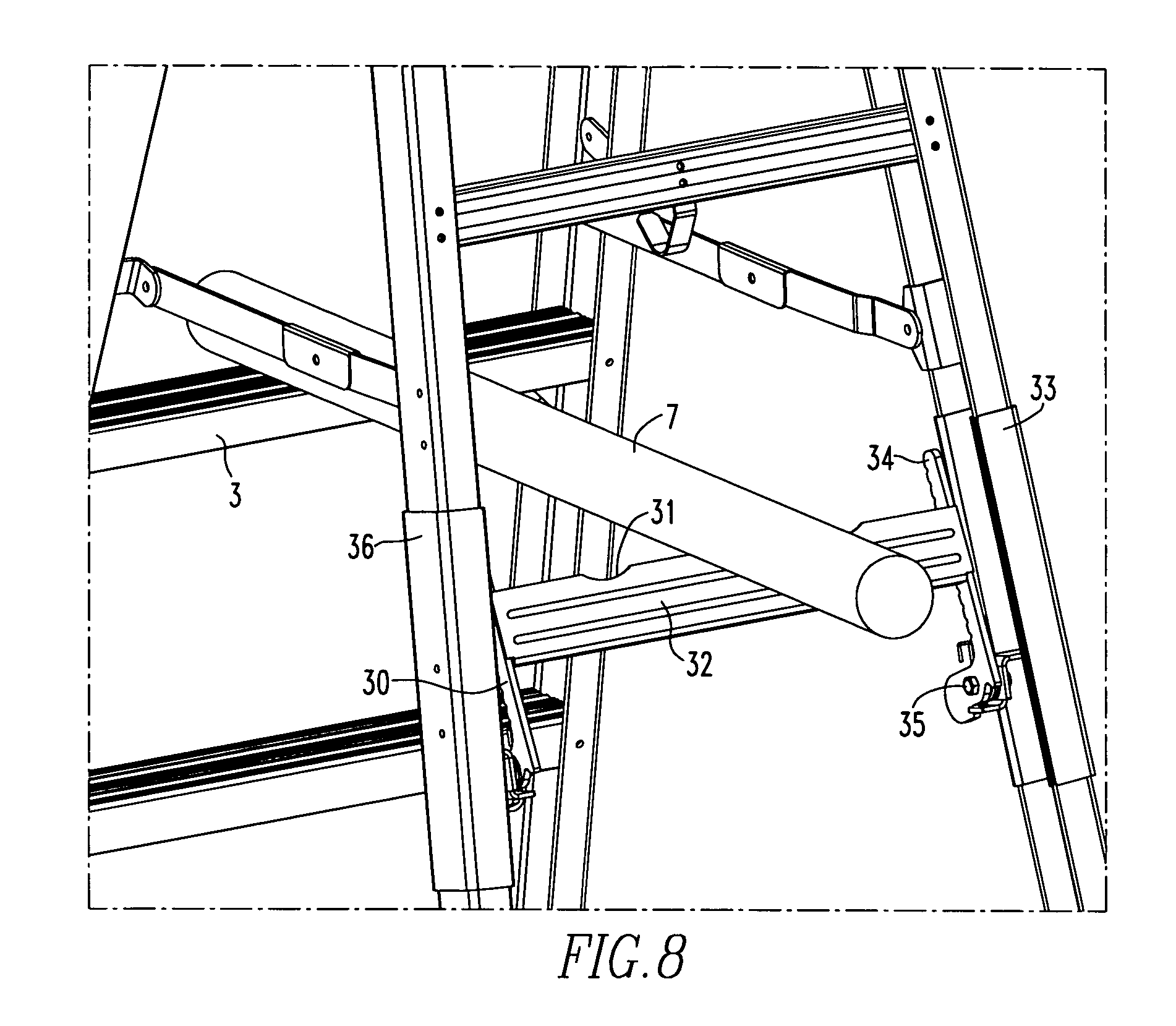
In an alternative embodiment, the pipe holder is designed to hold various sizes of pipe/tubing 7 up to 3 inches in diameter. FIG. 8 shows the pipe/tubing holder with pipe 7 in use. The hooks 30, 34 are connected by a steel stamping 32. The steel stamping 32 connecting the two hooks 30, 34 allows the user to operate both hooks with one hand. This one handed operation allows for safer handling of materials and tools. Attached to the rail are side shields 33, 36. The side shields 33, 36 wrap around the inside and the outside of the rail and protect the rail from being damaged by the pipe/tubing 7 or an errant cut by a hacksaw or PVC saw. As shown in FIG. 8, the pipe 7 can be held by the front step 3 and the scalloped divot 31 in the steel stamping 32. This allows the user a place to create and hold the necessary joints and fittings needed prior to installation. The hooks 30, 34 rotate on 35 outward creating a "V" for the pipe 7 to rest between the hooks 34, 30 and the rail shields 33, 36, as shown in an open position in FIG. 10. The hooks 34 and 30 may have notches and or round cuts in them to better hold a pipe or bar shape. The hooks are shown in a retracted position in FIG. 9.
Although the invention has been described in detail in the foregoing embodiments for the purpose of illustration, it is to be understood that such detail is solely for that purpose and that variations can be made therein by those skilled in the art without departing from the spirit and scope of the invention except as it may be described by the following claims.
* * * * *
D00000
D00001
D00002
D00003
D00004
D00005
D00006
D00007
D00008
XML
uspto.report is an independent third-party trademark research tool that is not affiliated, endorsed, or sponsored by the United States Patent and Trademark Office (USPTO) or any other governmental organization. The information provided by uspto.report is based on publicly available data at the time of writing and is intended for informational purposes only.
While we strive to provide accurate and up-to-date information, we do not guarantee the accuracy, completeness, reliability, or suitability of the information displayed on this site. The use of this site is at your own risk. Any reliance you place on such information is therefore strictly at your own risk.
All official trademark data, including owner information, should be verified by visiting the official USPTO website at www.uspto.gov. This site is not intended to replace professional legal advice and should not be used as a substitute for consulting with a legal professional who is knowledgeable about trademark law.