Threaded connector assembly and methods of making and using the same
Leven Feb
U.S. patent number 10,201,713 [Application Number 15/627,016] was granted by the patent office on 2019-02-12 for threaded connector assembly and methods of making and using the same. This patent grant is currently assigned to BOSTON SCIENTIFIC NEUROMODULATION CORPORATION. The grantee listed for this patent is Boston Scientific Neuromodulation Corporation. Invention is credited to Jacob B. Leven.
View All Diagrams
| United States Patent | 10,201,713 |
| Leven | February 12, 2019 |
Threaded connector assembly and methods of making and using the same
Abstract
A connector assembly includes a receptacle body that defines a portion of a connector lumen and further includes connector contacts disposed within the receptacle body along the connector lumen. The connector assembly further includes a rotational member that defines another portion of the connector lumen and includes a head portion and an elongated portion. The elongated portion defines an inner surface and an outer surface. The outer surface is rotatably coupled to the receptacle body. Fastener threading is disposed along at least a portion of the inner surface of the elongated portion. The receptacle body and rotational member are configured and arranged to receive a portion of a lead or a lead extension in the connector lumen.
| Inventors: | Leven; Jacob B. (Huntingdon Beach, CA) | ||||||||||
|---|---|---|---|---|---|---|---|---|---|---|---|
| Applicant: |
|
||||||||||
| Assignee: | BOSTON SCIENTIFIC NEUROMODULATION
CORPORATION (Valencia, CA) |
||||||||||
| Family ID: | 60661552 | ||||||||||
| Appl. No.: | 15/627,016 | ||||||||||
| Filed: | June 19, 2017 |
Prior Publication Data
| Document Identifier | Publication Date | |
|---|---|---|
| US 20170361108 A1 | Dec 21, 2017 | |
Related U.S. Patent Documents
| Application Number | Filing Date | Patent Number | Issue Date | ||
|---|---|---|---|---|---|
| 62352452 | Jun 20, 2016 | ||||
| Current U.S. Class: | 1/1 |
| Current CPC Class: | A61N 1/05 (20130101); A61N 1/3752 (20130101) |
| Current International Class: | A61N 1/00 (20060101); A61N 1/375 (20060101); A61N 1/05 (20060101) |
References Cited [Referenced By]
U.S. Patent Documents
| 3222471 | December 1965 | Steinkamp |
| 3601747 | August 1971 | Prall et al. |
| 3718142 | February 1973 | Mulier |
| 3757789 | September 1973 | Shanker |
| 3771106 | November 1973 | Matsumoto et al. |
| 3908668 | September 1975 | Bolduc |
| 3951154 | April 1976 | Hartlaub |
| 3990727 | November 1976 | Gallagher |
| 4003616 | January 1977 | Springer |
| 4112953 | September 1978 | Shanker et al. |
| 4142532 | March 1979 | Ware |
| 4180078 | December 1979 | Anderson |
| 4245642 | January 1981 | Skubitz et al. |
| 4259962 | April 1981 | Peers-Trevarton |
| 4310001 | January 1982 | Comben |
| 4364625 | December 1982 | Baker et al. |
| 4367907 | January 1983 | Buck |
| 4411276 | October 1983 | Dickhudt et al. |
| 4411277 | October 1983 | Dickhudt |
| 4461194 | July 1984 | Moore |
| 4466441 | August 1984 | Skubitz et al. |
| 4516820 | May 1985 | Kuzma |
| RE31990 | September 1985 | Sluetz et al. |
| 4540236 | September 1985 | Peers-Trevarton |
| 4602624 | July 1986 | Naples et al. |
| 4603696 | August 1986 | Cross, Jr. et al. |
| 4614395 | September 1986 | Peers-Trevarton |
| 4630611 | December 1986 | King |
| 4695116 | September 1987 | Bailey et al. |
| 4695117 | September 1987 | Kysiak |
| 4712557 | December 1987 | Harris |
| 4715380 | December 1987 | Harris |
| 4744370 | May 1988 | Harris |
| 4784141 | November 1988 | Peers-Trevarton |
| 4832032 | May 1989 | Schneider |
| 4840580 | June 1989 | Saell et al. |
| 4850359 | July 1989 | Putz |
| 4860750 | August 1989 | Frey et al. |
| 4867708 | September 1989 | Iizuka |
| 4869255 | September 1989 | Putz |
| 4898173 | February 1990 | Daglow et al. |
| 4899753 | February 1990 | Inoue et al. |
| 4951687 | August 1990 | Ufford et al. |
| 4995389 | February 1991 | Harris |
| 5000177 | March 1991 | Hoffman et al. |
| 5000194 | March 1991 | van den Honert et al. |
| 5007435 | April 1991 | Doan et al. |
| 5007864 | April 1991 | Stutz, Jr. |
| 5070605 | December 1991 | Daglow et al. |
| 5082453 | January 1992 | Stutz, Jr. |
| 5086773 | February 1992 | Ware |
| 5135001 | August 1992 | Sinofsky et al. |
| 5193539 | March 1993 | Schulman et al. |
| 5193540 | March 1993 | Schulman et al. |
| 5201865 | April 1993 | Kuehn |
| 5241957 | September 1993 | Camps et al. |
| 5252090 | October 1993 | Giurtino et al. |
| 5261395 | November 1993 | Oleen et al. |
| 5312439 | May 1994 | Loeb |
| 5324312 | June 1994 | Stokes et al. |
| 5330521 | July 1994 | Cohen |
| 5336246 | August 1994 | Dantanarayana |
| 5348481 | September 1994 | Ortiz |
| 5354326 | October 1994 | Comben et al. |
| 5358514 | October 1994 | Schulman et al. |
| 5368496 | November 1994 | Ranalletta et al. |
| 5374279 | December 1994 | Duffin, Jr. et al. |
| 5374285 | December 1994 | Vaiani et al. |
| 5383913 | January 1995 | Schiff |
| 5413595 | May 1995 | Stutz, Jr. |
| 5433734 | July 1995 | Stokes et al. |
| 5435731 | July 1995 | Kang |
| 5458629 | October 1995 | Baudino et al. |
| 5486202 | January 1996 | Bradshaw |
| 5489225 | February 1996 | Julian |
| 5509928 | April 1996 | Acken |
| 5522874 | June 1996 | Gates |
| 5534019 | July 1996 | Paspa |
| 5545188 | August 1996 | Bradshaw et al. |
| 5545189 | August 1996 | Fayram |
| 5582180 | August 1996 | Manset et al. |
| 5560358 | October 1996 | Arnold et al. |
| 5679026 | October 1997 | Fain et al. |
| 5683433 | November 1997 | Carson |
| 5711316 | January 1998 | Elsberry et al. |
| 5713922 | February 1998 | King |
| 5720631 | February 1998 | Carson et al. |
| 5730628 | March 1998 | Hawkins |
| 5755743 | May 1998 | Volz et al. |
| 5766042 | June 1998 | Ries et al. |
| 5782892 | July 1998 | Castle et al. |
| 5796044 | August 1998 | Cobian et al. |
| 5800350 | September 1998 | Coppleson et al. |
| 5800495 | September 1998 | Machek et al. |
| 5807144 | September 1998 | Sivard |
| 5837006 | November 1998 | Ocel et al. |
| 5843141 | December 1998 | Bischoff et al. |
| 5843148 | December 1998 | Gijsbers et al. |
| 5906634 | May 1999 | Flynn et al. |
| 5931861 | August 1999 | Werner et al. |
| 5938688 | August 1999 | Schiff |
| 5951595 | September 1999 | Moberg et al. |
| 5968082 | October 1999 | Heil |
| 5987361 | November 1999 | Mortimer |
| 5989077 | November 1999 | Mast et al. |
| 6006135 | December 1999 | Kast et al. |
| 6018684 | January 2000 | Bartig et al. |
| 6038479 | March 2000 | Werner et al. |
| 6038481 | March 2000 | Werner et al. |
| 6042432 | March 2000 | Hashazawa et al. |
| 6051017 | April 2000 | Loeb et al. |
| 6080188 | June 2000 | Rowley et al. |
| 6112120 | August 2000 | Correas |
| 6112121 | August 2000 | Paul et al. |
| 6125302 | September 2000 | Kuzma |
| 6134478 | October 2000 | Spehr |
| 6154678 | November 2000 | Lauro |
| 6161047 | December 2000 | King et al. |
| 6162101 | December 2000 | Fischer et al. |
| 6164284 | December 2000 | Schulman et al. |
| 6167311 | December 2000 | Rezai |
| 6167314 | December 2000 | Fischer, Sr. et al. |
| 6175710 | January 2001 | Kamaji et al. |
| 6181969 | January 2001 | Gord |
| 6185452 | February 2001 | Schulman et al. |
| 6192278 | February 2001 | Werner et al. |
| 6198969 | March 2001 | Kuzma |
| 6208894 | March 2001 | Schulman et al. |
| 6224450 | May 2001 | Norton |
| 6271094 | August 2001 | Boyd et al. |
| 6295944 | October 2001 | Lovett |
| 6319021 | November 2001 | Billman |
| 6321126 | November 2001 | Kuzma |
| 6322559 | November 2001 | Daulton et al. |
| 6343233 | January 2002 | Werner et al. |
| 6364278 | April 2002 | Lin et al. |
| 6370434 | April 2002 | Zhang et al. |
| 6391985 | May 2002 | Goode et al. |
| 6397108 | May 2002 | Camps et al. |
| 6415168 | July 2002 | Putz |
| 6428336 | August 2002 | Akerfeldt |
| 6428368 | August 2002 | Hawkins et al. |
| 6430442 | August 2002 | Peters et al. |
| 6466824 | October 2002 | Struble |
| 6473654 | October 2002 | Chinn |
| 6498952 | December 2002 | Imani et al. |
| 6510347 | January 2003 | Borkan |
| 6516227 | February 2003 | Meadows et al. |
| 6556873 | April 2003 | Smits |
| 6564078 | May 2003 | Marino et al. |
| 6604283 | August 2003 | Kuzma |
| 6605094 | August 2003 | Mann et al. |
| 6609029 | August 2003 | Mann et al. |
| 6609032 | August 2003 | Woods et al. |
| 6654641 | November 2003 | Froberg |
| 6662035 | December 2003 | Sochor |
| 6663570 | December 2003 | Mott |
| 6671534 | December 2003 | Putz |
| 6671553 | December 2003 | Helland et al. |
| 6678564 | January 2004 | Ketterl et al. |
| 6725096 | April 2004 | Chinn et al. |
| 6741892 | May 2004 | Meadows et al. |
| 6757039 | June 2004 | Ma |
| 6757970 | July 2004 | Kuzma et al. |
| 6799991 | October 2004 | Williams et al. |
| 6805675 | October 2004 | Gardeski et al. |
| 6854994 | February 2005 | Stein et al. |
| 6878013 | April 2005 | Behan |
| 6895276 | May 2005 | Kast et al. |
| 6913478 | July 2005 | Lamrey |
| 6921295 | July 2005 | Sommer et al. |
| 6968235 | November 2005 | Belden et al. |
| 6980863 | December 2005 | van Venrooj et al. |
| 7027852 | April 2006 | Helland |
| 7047084 | May 2006 | Erickson et al. |
| 7058452 | June 2006 | Dahberg |
| 7069081 | June 2006 | Biggs et al. |
| 7083474 | August 2006 | Fleck et al. |
| 7108549 | September 2006 | Lyu et al. |
| 7110827 | September 2006 | Sage et al. |
| 7128600 | October 2006 | Osypka |
| 7155283 | December 2006 | Ries et al. |
| 7164951 | January 2007 | Ries et al. |
| 7168165 | January 2007 | Calzada et al. |
| 7191009 | March 2007 | Laske et al. |
| 7195523 | March 2007 | Naviaux |
| 7203548 | April 2007 | Whitehurst et al. |
| 7225034 | May 2007 | Ries et al. |
| 7231253 | June 2007 | Tidemand et al. |
| 7241180 | July 2007 | Rentas |
| 7242987 | July 2007 | Holleman et al. |
| 7244150 | July 2007 | Brase et al. |
| 7270568 | September 2007 | Osypka |
| 7283878 | October 2007 | Brostrom et al. |
| 7286882 | October 2007 | Cole |
| 7287995 | October 2007 | Stein et al. |
| 7292890 | November 2007 | Whitehurst et al. |
| 7396335 | July 2008 | Gardeski et al. |
| 7402083 | July 2008 | Kast et al. |
| 7422487 | September 2008 | Osypka |
| 7430958 | October 2008 | Wong |
| 7437193 | October 2008 | Parramon et al. |
| 7450997 | November 2008 | Pianca et al. |
| 7489971 | February 2009 | Franz |
| 7512446 | March 2009 | Honeck |
| 7516447 | March 2009 | Drew |
| 7526339 | April 2009 | Lahti et al. |
| 7539542 | May 2009 | Malinowski |
| 7548788 | June 2009 | Chinn et al. |
| 7554493 | June 2009 | Rahman |
| 7583999 | September 2009 | Bedenbaugh |
| 7585190 | September 2009 | Osypka |
| 7650184 | January 2010 | Walter |
| 7668601 | February 2010 | Hegland et al. |
| 7672734 | March 2010 | Anderson et al. |
| 7736191 | June 2010 | Sochor |
| 7758384 | July 2010 | Alexander et al. |
| 7761165 | July 2010 | He et al. |
| 7761985 | July 2010 | Hegland et al. |
| 7783359 | August 2010 | Meadows |
| 7792590 | September 2010 | Pianca et al. |
| 7798864 | September 2010 | Barker et al. |
| 7809446 | October 2010 | Meadows |
| 7822482 | October 2010 | Gerber |
| 7840188 | November 2010 | Kurokawa |
| 7848802 | December 2010 | Goetz |
| 7856707 | December 2010 | Cole |
| 7860570 | December 2010 | Whitehurst et al. |
| 7949395 | May 2011 | Kuzma |
| 7974705 | July 2011 | Zdeblick et al. |
| 7974706 | July 2011 | Moffitt et al. |
| 7979140 | July 2011 | Schulman |
| 8000808 | August 2011 | Hegland et al. |
| 8019440 | September 2011 | Kokones et al. |
| 8036755 | October 2011 | Franz |
| 8041309 | October 2011 | Kurokawa |
| 8046073 | October 2011 | Pianca |
| 8046074 | October 2011 | Barker |
| 8078280 | December 2011 | Sage |
| 8099177 | January 2012 | Dahlberg |
| 8100726 | January 2012 | Harlan et al. |
| 8140163 | March 2012 | Daglow et al. |
| 8175710 | May 2012 | He |
| 8190259 | May 2012 | Smith et al. |
| 8206180 | June 2012 | Kast et al. |
| 8224450 | July 2012 | Brase |
| 8225504 | July 2012 | Dye et al. |
| 8239042 | August 2012 | Chinn et al. |
| 8271094 | September 2012 | Moffitt et al. |
| 8295944 | October 2012 | Howard et al. |
| 8301255 | October 2012 | Barker |
| 8321025 | November 2012 | Bedenbaugh |
| 8342887 | January 2013 | Gleason et al. |
| 8359107 | January 2013 | Pianca et al. |
| 8364278 | January 2013 | Pianca et al. |
| 8391985 | March 2013 | McDonald |
| 8412330 | April 2013 | Kast et al. |
| 8527054 | September 2013 | North |
| 8583237 | November 2013 | Bedenbaugh |
| 8600507 | December 2013 | Brase et al. |
| 8682439 | March 2014 | DeRohan et al. |
| 8688235 | April 2014 | Pianca et al. |
| 8784143 | July 2014 | Edgell et al. |
| 8831742 | September 2014 | Pianca et al. |
| 8849396 | September 2014 | DeRohan et al. |
| 8849415 | September 2014 | Bedenbaugh |
| 8897876 | November 2014 | Sundaramurthy et al. |
| 8897891 | November 2014 | Romero |
| 8968331 | March 2015 | Sochor |
| 9101775 | August 2015 | Barker |
| 9149630 | October 2015 | Howard et al. |
| 9162048 | October 2015 | Romero et al. |
| 9270070 | February 2016 | Pianca |
| 9289596 | March 2016 | Leven |
| 9352147 | May 2016 | Nguyen-stella et al. |
| 9381348 | July 2016 | Romero et al. |
| 9403022 | August 2016 | Ries et al. |
| 9409032 | August 2016 | Brase et al. |
| 9440066 | September 2016 | Black |
| 9498620 | November 2016 | Romero et al. |
| 9504839 | November 2016 | Leven |
| 9656093 | May 2017 | Villarta et al. |
| 2001/0023368 | September 2001 | Black et al. |
| 2002/0143376 | October 2002 | Chinn et al. |
| 2002/0156513 | October 2002 | Borkan |
| 2002/0183817 | December 2002 | Van Venrooij et al. |
| 2003/0163171 | August 2003 | Kast et al. |
| 2004/0064164 | April 2004 | Ries et al. |
| 2004/0230268 | November 2004 | Huff et al. |
| 2004/0260373 | December 2004 | Ries et al. |
| 2005/0015130 | January 2005 | Gill |
| 2005/0027326 | February 2005 | Ries et al. |
| 2005/0027327 | February 2005 | Ries et al. |
| 2005/0038489 | February 2005 | Grill |
| 2005/0043770 | February 2005 | Hine et al. |
| 2005/0043771 | February 2005 | Sommer et al. |
| 2005/0107860 | May 2005 | Ignagni |
| 2005/0137665 | June 2005 | Cole |
| 2005/0171587 | August 2005 | Daglow et al. |
| 2005/0186829 | August 2005 | Balsells |
| 2005/0272280 | December 2005 | Osypka |
| 2006/0015163 | January 2006 | Brown |
| 2006/0025841 | February 2006 | McIntyre |
| 2006/0030918 | February 2006 | Chinn |
| 2006/0167522 | July 2006 | Malinowski |
| 2006/0224208 | October 2006 | Naviaux |
| 2006/0247697 | November 2006 | Sharma et al. |
| 2006/0247749 | November 2006 | Colvin |
| 2006/0259106 | November 2006 | Arnholdt et al. |
| 2007/0042648 | February 2007 | Balsells |
| 2007/0142889 | June 2007 | Whitehurst et al. |
| 2007/0150036 | June 2007 | Anderson |
| 2007/0161294 | July 2007 | Brase et al. |
| 2007/0168007 | July 2007 | Kuzma et al. |
| 2007/0203546 | August 2007 | Stone et al. |
| 2007/0219551 | September 2007 | Honour et al. |
| 2008/0077186 | March 2008 | Thompson et al. |
| 2008/0103580 | May 2008 | Gerber |
| 2008/0114230 | May 2008 | Addis |
| 2008/0139031 | June 2008 | Ries et al. |
| 2008/0177167 | July 2008 | Janzig et al. |
| 2008/0208277 | August 2008 | Janzig et al. |
| 2008/0208278 | August 2008 | Janzig et al. |
| 2008/0208279 | August 2008 | Janzig et al. |
| 2008/0215125 | September 2008 | Farah et al. |
| 2008/0255647 | October 2008 | Jensen et al. |
| 2008/0274651 | November 2008 | Boyd et al. |
| 2009/0054941 | February 2009 | Eggen et al. |
| 2009/0187222 | July 2009 | Barker |
| 2009/0204192 | August 2009 | Carlton et al. |
| 2009/0264943 | October 2009 | Barker |
| 2009/0276021 | November 2009 | Meadows et al. |
| 2009/0287191 | November 2009 | Ferren et al. |
| 2010/0029127 | February 2010 | Sjostedt |
| 2010/0030298 | February 2010 | Martens et al. |
| 2010/0036468 | February 2010 | Decre et al. |
| 2010/0057176 | March 2010 | Barker |
| 2010/0070012 | March 2010 | Chinn et al. |
| 2010/0076535 | March 2010 | Pianca et al. |
| 2010/0077606 | April 2010 | Black et al. |
| 2010/0082076 | April 2010 | Lee et al. |
| 2010/0094387 | April 2010 | Pianca et al. |
| 2010/0100152 | April 2010 | Martens et al. |
| 2010/0268298 | October 2010 | Moffitt et al. |
| 2010/0269338 | October 2010 | Dye |
| 2010/0269339 | October 2010 | Dye et al. |
| 2010/0287770 | November 2010 | Dadd et al. |
| 2011/0004267 | January 2011 | Meadows |
| 2011/0005069 | January 2011 | Pianca |
| 2011/0022100 | January 2011 | Brase et al. |
| 2011/0047795 | March 2011 | Turner et al. |
| 2011/0056076 | March 2011 | Hegland et al. |
| 2011/0077699 | March 2011 | Swanson et al. |
| 2011/0078900 | April 2011 | Pianca et al. |
| 2011/0130803 | June 2011 | McDonald |
| 2011/0130816 | June 2011 | Howard et al. |
| 2011/0130817 | June 2011 | Chen |
| 2011/0130818 | June 2011 | Chen |
| 2011/0131808 | June 2011 | Gill |
| 2011/0184480 | July 2011 | Kast et al. |
| 2011/0238129 | September 2011 | Moffitt et al. |
| 2011/0245903 | October 2011 | Schulte et al. |
| 2011/0270330 | November 2011 | Janzig et al. |
| 2011/0301665 | December 2011 | Mercanzini et al. |
| 2011/0313500 | December 2011 | Barker et al. |
| 2012/0016378 | January 2012 | Pianca et al. |
| 2012/0046710 | February 2012 | DiGiore et al. |
| 2012/0053646 | March 2012 | Brase et al. |
| 2012/0071937 | March 2012 | Sundaramurthy et al. |
| 2012/0071949 | March 2012 | Pianca et al. |
| 2012/0165911 | June 2012 | Pianca |
| 2012/0185019 | July 2012 | Schramm et al. |
| 2012/0197375 | August 2012 | Pianca et al. |
| 2012/0203302 | August 2012 | Moffit et al. |
| 2012/0203316 | August 2012 | Moffitt et al. |
| 2012/0203320 | August 2012 | DiGiore et al. |
| 2012/0203321 | August 2012 | Moffitt et al. |
| 2012/0232603 | September 2012 | Sage |
| 2012/0253443 | October 2012 | Dilmaghanian et al. |
| 2012/0259386 | October 2012 | DeRohan et al. |
| 2012/0316615 | December 2012 | DiGiore et al. |
| 2013/0053864 | February 2013 | Geroy et al. |
| 2013/0105071 | May 2013 | DiGiore et al. |
| 2013/0109254 | May 2013 | Klardie et al. |
| 2013/0110201 | May 2013 | Bonde |
| 2013/0116754 | May 2013 | Sharma et al. |
| 2013/0149031 | June 2013 | Changsrivong et al. |
| 2013/0197424 | August 2013 | Bedenbaugh |
| 2013/0197602 | August 2013 | Pianca et al. |
| 2013/0197603 | August 2013 | Eiger |
| 2013/0218154 | August 2013 | Carbunaru |
| 2013/0261684 | October 2013 | Howard |
| 2013/0288501 | October 2013 | Russell et al. |
| 2013/0304140 | November 2013 | Derohan et al. |
| 2013/0317587 | November 2013 | Barker |
| 2013/0325091 | December 2013 | Pianca et al. |
| 2014/0039587 | February 2014 | Romero |
| 2014/0088666 | March 2014 | Goetz et al. |
| 2014/0142671 | May 2014 | Moffitt et al. |
| 2014/0148885 | May 2014 | DeRohan et al. |
| 2014/0180375 | June 2014 | Pianca et al. |
| 2014/0353001 | December 2014 | Romero et al. |
| 2014/0358207 | December 2014 | Romero |
| 2014/0358208 | December 2014 | Howard et al. |
| 2014/0358209 | December 2014 | Romero et al. |
| 2014/0358210 | December 2014 | Howard et al. |
| 2015/0018915 | January 2015 | Leven |
| 2015/0021817 | January 2015 | Romero et al. |
| 2015/0045864 | February 2015 | Howard |
| 2015/0066120 | March 2015 | Govea |
| 2015/0151113 | June 2015 | Govea et al. |
| 2015/0209575 | July 2015 | Black |
| 2015/0360023 | December 2015 | Howard et al. |
| 2015/0374978 | December 2015 | Howard et al. |
| 2016/0059019 | March 2016 | Malinowski et al. |
| 2016/0129242 | May 2016 | Malinowski |
| 2016/0129265 | May 2016 | Malinowski |
| 2016/0158558 | June 2016 | Shanahan et al. |
| 2016/0228692 | August 2016 | Steinke et al. |
| 2016/0296745 | October 2016 | Govea et al. |
| 2017/0072187 | March 2017 | Howard et al. |
| 2017/0143978 | May 2017 | Barker |
| 2017/0203104 | July 2017 | Nageri et al. |
| 0580928 | Feb 1994 | EP | |||
| 0650694 | Jul 1998 | EP | |||
| 0832667 | Feb 2004 | EP | |||
| 1181947 | Jan 2006 | EP | |||
| 1625875 | Feb 2006 | EP | |||
| 2092952 | Aug 2009 | EP | |||
| 1997032628 | Sep 1997 | WO | |||
| 1999055411 | Feb 2000 | WO | |||
| 2000038574 | Jul 2000 | WO | |||
| 2001058520 | Aug 2001 | WO | |||
| 2002068042 | Sep 2002 | WO | |||
| 2004045707 | Jun 2004 | WO | |||
| 2008018067 | Feb 2008 | WO | |||
| 2008053789 | May 2008 | WO | |||
| 2008100841 | Aug 2008 | WO | |||
| 2009025816 | Feb 2009 | WO | |||
| 2009102536 | Aug 2009 | WO | |||
| 2009/148939 | Dec 2009 | WO | |||
| 2013162775 | Oct 2013 | WO | |||
| 2014018092 | Jan 2014 | WO | |||
Attorney, Agent or Firm: Lowe Graham Jones PLLC Black; Bruce E.
Parent Case Text
CROSS-REFERENCE TO RELATED APPLICATIONS
This application claims the benefit under 35 U.S.C. .sctn. 119(e) of U.S. Provisional Patent Application Ser. No. 62/352,452, filed Jun. 20, 2016, which is incorporated herein by reference.
Claims
What is claimed as new and desired to be protected by Letters Patent of the United States is:
1. A connector assembly comprising: a receptacle body defining a first portion of a connector lumen and comprising a plurality of connector contacts disposed within the receptacle body along the connector lumen; and a rotational member defining a second portion of the connector lumen and comprising a head portion and an elongated portion extending from the head portion, the elongated portion comprising an inner surface and an outer surface, wherein the outer surface is rotatably coupled to the receptacle body, wherein fastener threading is disposed along at least a portion of the inner surface so that the fastener threading extends along at least part of the second portion of the connector lumen, wherein the receptacle body and rotational member are configured and arranged to receive a portion of a lead or lead extension in the connector lumen.
2. The connector assembly of claim 1, wherein an axial length of the fastener threading predetermines a stopping point for the lead or lead extension received in the rotational member.
3. The connector assembly of claim 1, wherein the fastener threading is disposed along an entire length of the rotational member.
4. The connector assembly of claim 1, wherein the head portion of the rotational member defines a flared aperture into the connector lumen to facilitate receiving the portion of the lead or lead extension.
5. The connector assembly of claim 1, wherein an outer surface of the head portion of the rotational member comprises a textured outer surface.
6. A connector assembly comprising: a receptacle body defining a portion of a connector lumen and comprising a plurality of connector contacts disposed within the receptacle body along the connector lumen; rotational member defining another portion of the connector lumen and comprising a head portion and an elongated portion, the elongated portion comprising an inner surface and an outer surface, wherein the outer surface is rotatably coupled to the receptacle body, wherein fastener threading is disposed along at least a portion of the inner surface; and an end stop disposed within the receptacle body and terminating the connector lumen, wherein the receptacle body and rotational member are configured and arranged to receive a portion of a lead or lead extension in the connector lumen.
7. The connector assembly of claim 6, wherein the end stop is embedded into the receptacle body.
8. The connector assembly of claim 6, wherein the end stop is integrally formed as part of the receptacle body.
9. A connector assembly comprising: a receptacle body defining a portion of a connector lumen and comprising a plurality of connector contacts disposed within the receptacle body along the connector lumen; a rotational member defining another portion of the connector lumen and comprising a head portion and an elongated portion, the elongated portion comprising an inner surface and an outer surface, wherein the outer surface is rotatably coupled to the receptacle body, wherein fastener threading is disposed along at least a portion of the inner surface; and a collar disposed within the receptacle body, wherein the rotational member is rotatably attached to the collar, wherein the receptacle body and rotational member are configured and arranged to receive a portion of a lead or lead extension in the connector lumen.
10. The connector assembly of claim 9, wherein the collar is embedded into the receptacle body.
11. The connector assembly of claim 9, wherein the collar is integrally formed as part of the receptacle body.
12. The connector assembly of claim 9, further comprising a stop member extending radially from the rotational member for engagement with the collar, wherein the stop member restrict longitudinal movement of the rotational member relative to the receptacle body.
13. An electrical stimulation system comprising: the connector assembly of claim 1; an electrical stimulation lead comprising an externally threaded portion configured to engage the fastener threading of the rotational member of the connector assembly; and a control module coupleable to the electrical stimulation lead, the control module comprising a housing, and an electronic subassembly disposed in the housing.
14. The electrical stimulation system of claim 13, wherein the connector assembly is disposed in the housing of the control module.
15. The electrical stimulation system of claim 13, further comprising a lead extension coupleable to both the electrical stimulation lead and the control module, wherein lead extension comprises the connector assembly.
16. An electrical stimulation system, comprising: the connector assembly of claim 6; and an electrical stimulation lead comprising a lead body having a distal end portion, a proximal end portion, and a longitudinal length; a plurality of electrodes disposed along the distal end portion of the lead body; a plurality of terminals disposed along the proximal end portion of the lead body; a plurality of conductors electrically coupling the plurality of terminals to the plurality of electrodes; and an externally threaded portion disposed along the proximal end portion of the lead body distal to the plurality of terminals and configured for threaded engagement with the fastener threading of the connector assembly.
17. The electrical stimulation system of claim 16, wherein the externally threaded portion comprises an externally threaded sleeve.
18. The electrical stimulation system of claim 16, wherein the externally threaded portion is machined into the lead.
19. The electrical stimulation system of claim 16, wherein the externally threaded portion comprises a major diameter sized to fit through a percutaneous introducer.
20. An electrical stimulation system comprising: the connector assembly of claim 9; an electrical stimulation lead comprising an externally threaded portion configured to engage the fastener threading of the rotational member of the connector assembly; and a control module coupleable to the electrical stimulation lead, the control module comprising a housing, and an electronic subassembly disposed in the housing.
Description
FIELD
The present invention is directed to the area of implantable electrical stimulation systems and methods of making and using the systems. The present invention is also directed to implantable electrical stimulation leads having a threaded connector assembly, as well as methods of making and using the leads and electrical stimulation systems.
BACKGROUND
Implantable electrical stimulation systems have proven therapeutic in a variety of diseases and disorders. For example, spinal cord stimulation systems have been used as a therapeutic modality for the treatment of chronic pain syndromes. Peripheral nerve stimulation has been used to treat chronic pain syndrome and incontinence, with a number of other applications under investigation. Functional electrical stimulation systems have been applied to restore some functionality to paralyzed extremities in spinal cord injury patients. Stimulation of the brain, such as deep brain stimulation, can be used to treat a variety of diseases or disorders.
Stimulators have been developed to provide therapy for a variety of treatments. A stimulator can include a control module (with a pulse generator), one or more leads, and an array of stimulator electrodes on each lead. The stimulator electrodes are in contact with or near the nerves, muscles, or other tissue to be stimulated. The pulse generator in the control module generates electrical pulses that are delivered by the electrodes to body tissue.
BRIEF SUMMARY
In one embodiment, a connector assembly includes a receptacle body that defines a portion of a connector lumen and further includes a plurality of connector contacts disposed within the receptacle body along the connector lumen. The connector assembly further includes a rotational member that defines another portion of the connector lumen and includes a head portion and an elongated portion. The elongated portion defines an inner surface and an outer surface. The outer surface is rotatably coupled to the receptacle body. Fastener threading is disposed along at least a portion of the inner surface of the elongated portion. The receptacle body and rotational member are configured and arranged to receive a portion of a lead or a lead extension in the connector lumen.
In at least some embodiments, an axial length of the fastener threading predetermines a stopping point for the lead or lead extension when received in the rotational member.
In at least some embodiments, the fastener threading is disposed along an entire length of the rotational member.
In at least some embodiments, the head portion of the rotational member defines a flared aperture into the connector lumen to facilitate receiving the portion of the lead or lead extension.
In at least some embodiments, an outer surface of the head portion of the rotational member includes a textured outer surface.
In at least some embodiments, the connector assembly includes an end stop disposed within the receptacle body and terminating the connector lumen. The end stop may be embedded into the receptacle body or integrally formed as part of the receptacle body.
In at least some embodiments, the connector assembly includes a collar disposed within the receptacle body and the rotational member is rotatably attached to the collar. The collar may be embedded into the receptacle body or integrally formed as part of the receptacle body.
In at least some embodiments, the connector assembly includes a stop member extending radially from the rotational member for engagement with the collar, and the stop member restricts longitudinal movement of the rotational member relative to the receptacle body.
In a further embodiment, an electrical stimulation system includes the connector assembly described above, an electrical stimulation lead and a control module. The electrical stimulation lead includes an externally threaded portion configured to engage the fastener threading of the rotational member of the connector assembly. The control module is coupleable to the electrical stimulation lead. The control module includes a housing and an electronic subassembly disposed in the housing.
In at least some embodiments, the connector assembly is disposed in the housing of the control module. Additionally or alternatively the electrical stimulation system includes a lead extension coupleable to both the electrical stimulation lead and the control module, wherein the lead extension includes the connector assembly.
In another embodiment, an electrical stimulation lead includes a lead body having a distal end portion, a proximal end portion, and a longitudinal length. The lead further includes a plurality of electrodes disposed along the distal end portion of the lead body and includes a plurality of terminals disposed along the proximal end portion of the lead body. The lead includes a plurality of conductors electrically coupling the plurality of terminals to the plurality of electrodes. Further, the lead includes an externally threaded portion disposed along proximal end portion of the lead distal to the plurality of terminals.
In at least some embodiments, the externally threaded portion includes an externally threaded sleeve or the externally threaded portion is machined into the lead. Additionally or alternatively, the externally threaded portion includes a major diameter sized to fit through a percutaneous introducer.
In yet another embodiment, an electrical stimulation system includes the aforementioned electrical stimulation lead and a connector assembly. The connector assembly defines a connector lumen for receiving the proximal end portion of the electrical stimulation lead. The connector assembly further includes a receptacle body, a plurality of connector contacts disposed within the receptacle body along the connector lumen, and a rotational member. The rotational member is rotatably coupled to the receptacle body and includes fastener threading to engage the externally threaded portion of the electrical stimulation lead.
BRIEF DESCRIPTION OF THE DRAWINGS
Non-limiting and non-exhaustive embodiments of the present invention are described with reference to the following drawings. In the drawings, like reference numerals refer to like parts throughout the various figures unless otherwise specified.
For a better understanding of the present invention, reference will be made to the following Detailed Description, which is to be read in association with the accompanying drawings, wherein:
FIG. 1 is a schematic view of one embodiment of an electrical stimulation system that includes a paddle lead electrically coupled to a control module, according to the invention;
FIG. 2 is a schematic view of one embodiment of an electrical stimulation system that includes a percutaneous lead electrically coupled to a control module, according to the invention;
FIG. 3A is a schematic view of one embodiment of the control module of FIG. 1 configured and arranged to electrically couple to an elongated device, according to the invention;
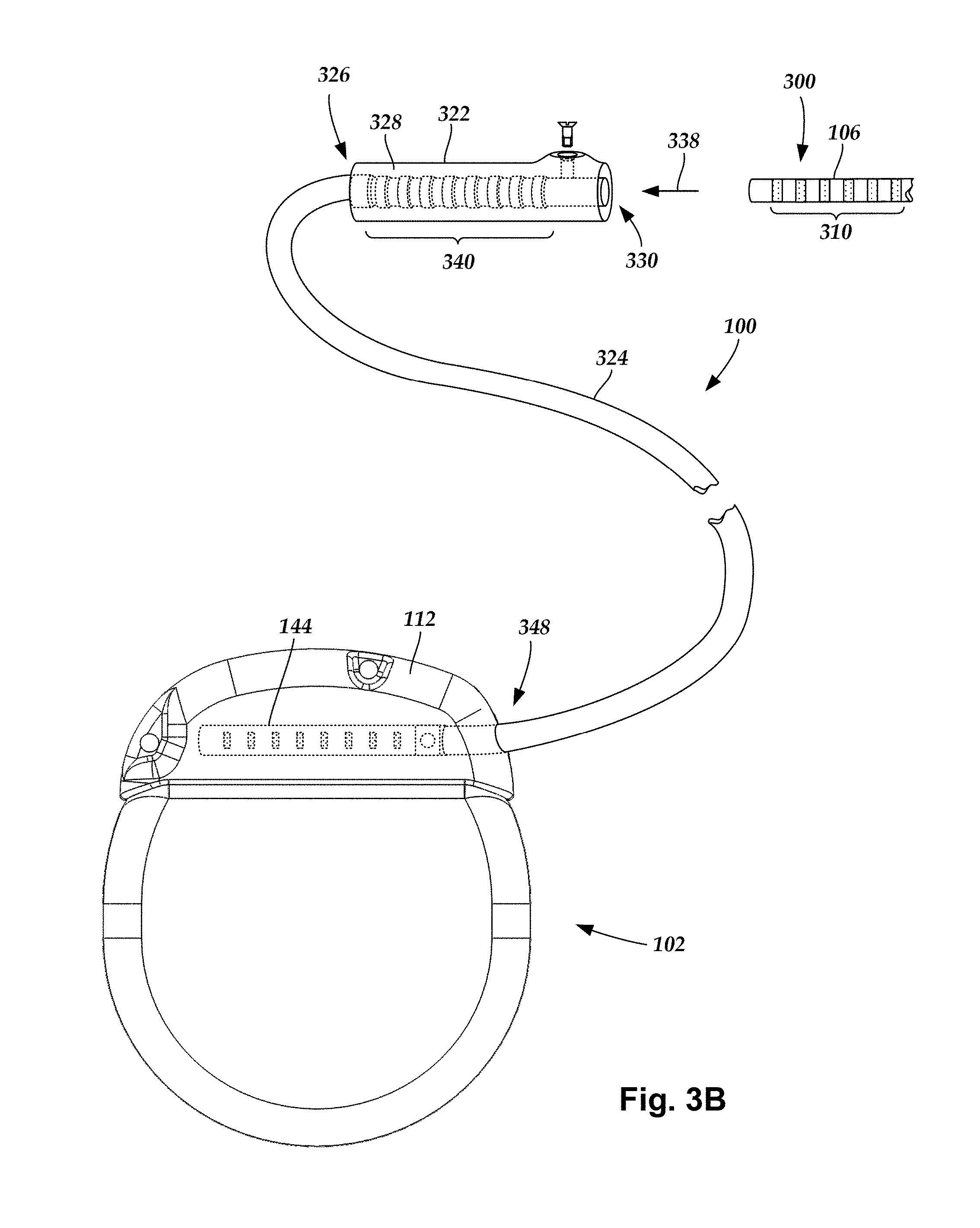
FIG. 3B is a schematic view of one embodiment of a lead extension configured and arranged to electrically couple the elongated device of FIG. 2 to the control module of FIG. 1, according to the invention;
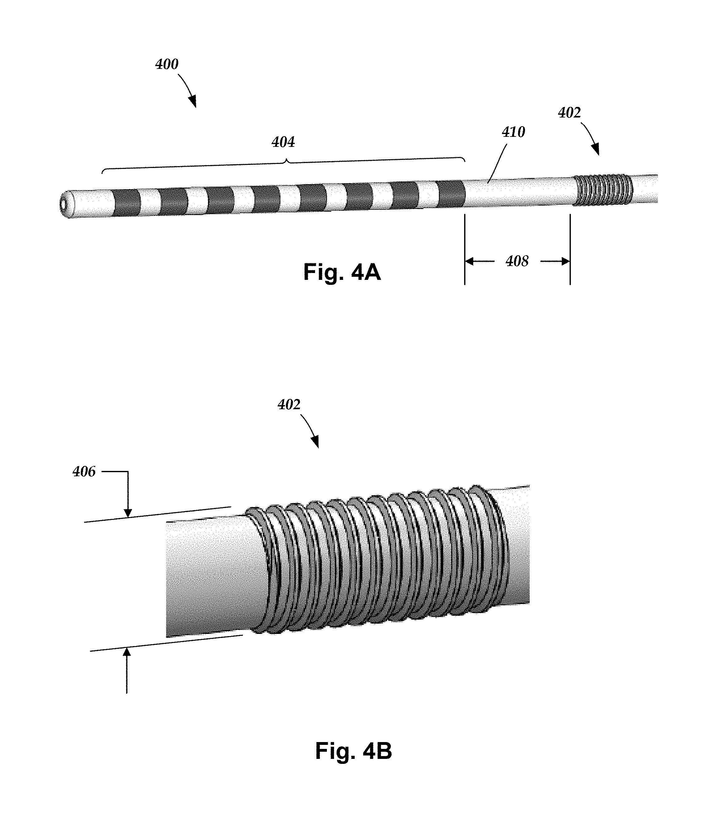
FIG. 4A is a schematic, perspective view of an insertable member of a lead according to at least some embodiments of the present invention;
FIG. 4B is a close-up view of a threaded sleeve for the insertable member of FIG. 4A;
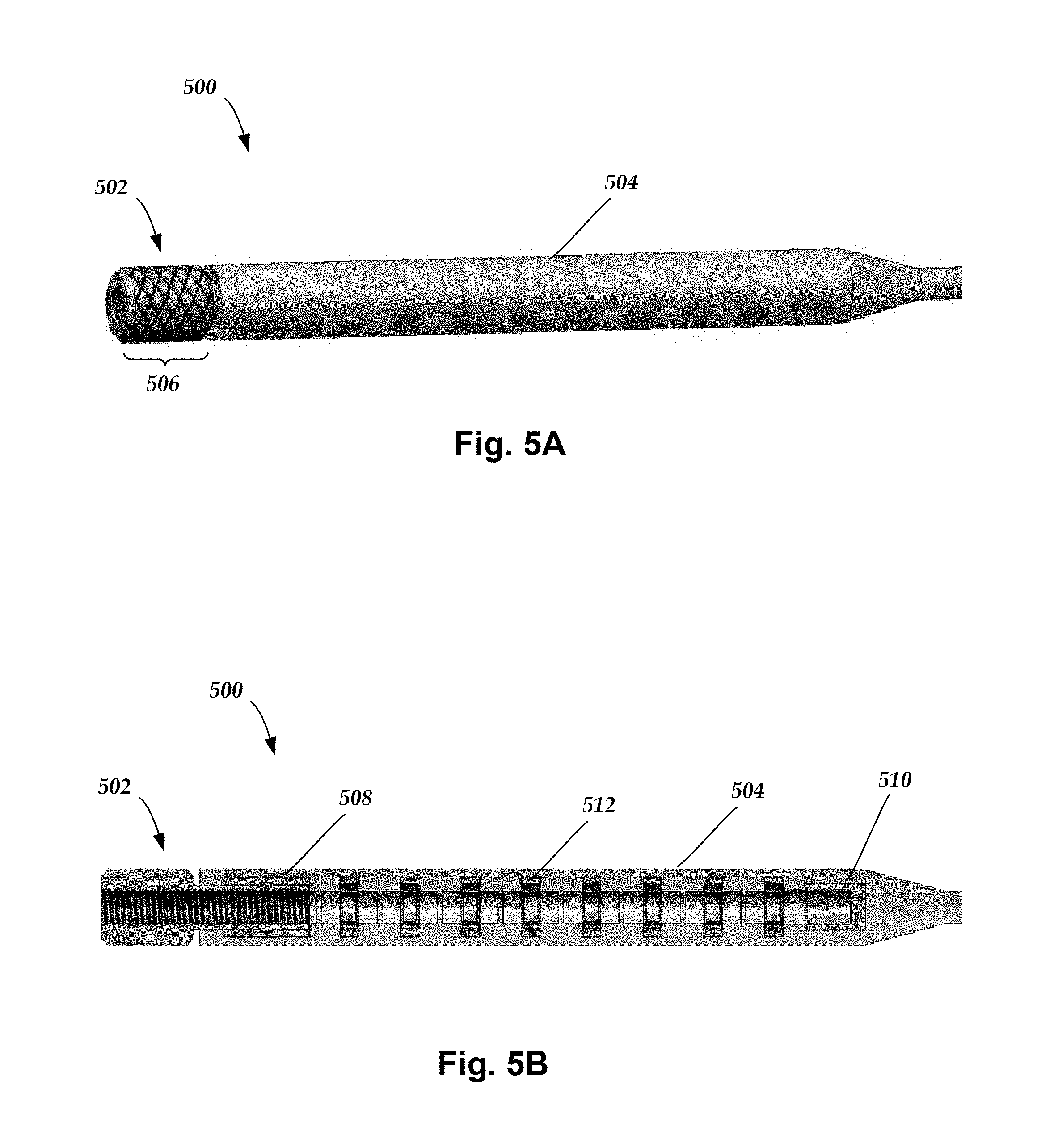
FIG. 5A is a schematic, perspective view of a receiving member of a lead according to at least some embodiments of the present invention;
FIG. 5B is a cross-section view of the receiving member of FIG. 5A;
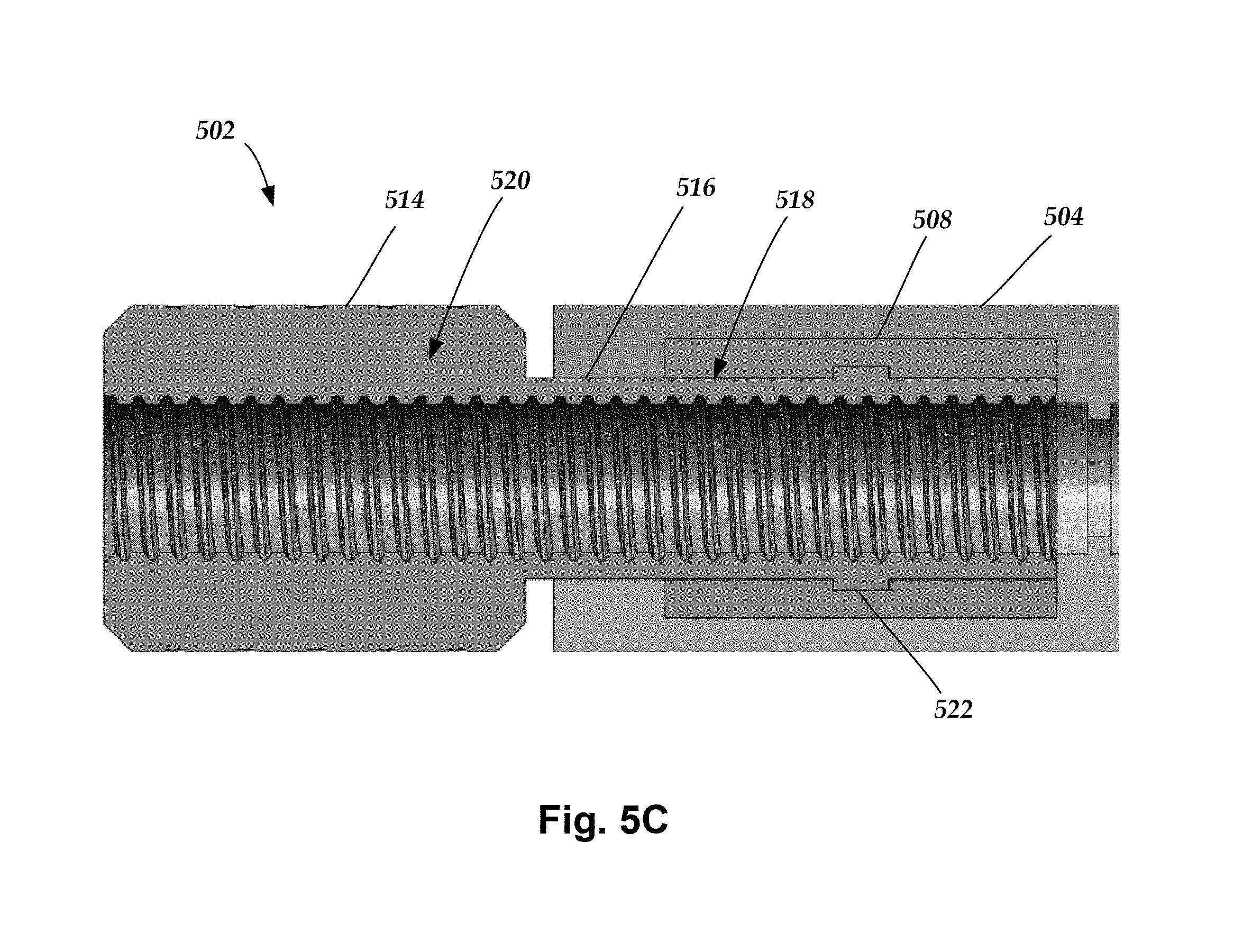
FIG. 5C is a close-up view of a threaded nut for the receiving member of FIG. 5B;
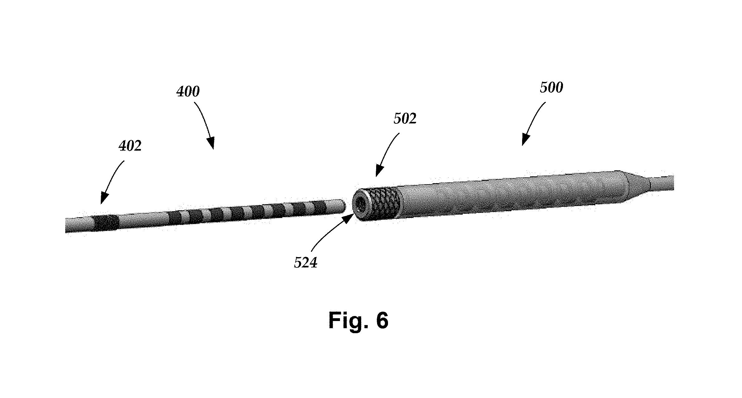
FIG. 6 is a schematic, perspective view of the insertable member of FIG. 4A just prior to insertion into the receiving member of FIG. 5A according to at least some embodiments of the present invention;
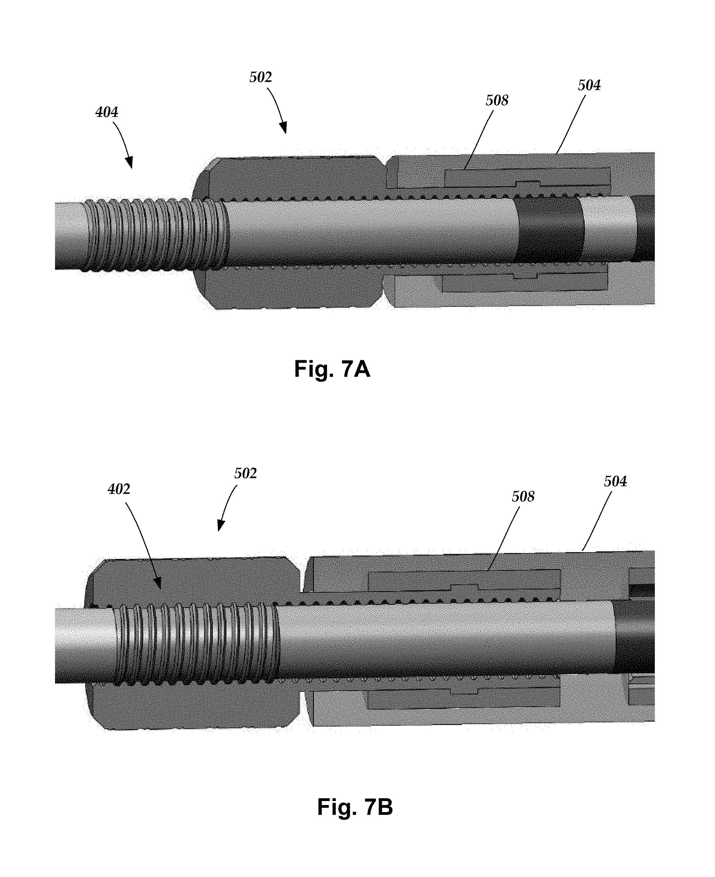
FIG. 7A is a close-up view of the insertable member of FIG. 6 partially inserted into the receiving member of FIG. 6 according to at least some embodiments of the present invention;
FIG. 7B is a close-up view of the insertable member of FIG. 6 fully inserted into the receiving member of FIG. 6 according to at least some embodiments of the present invention;
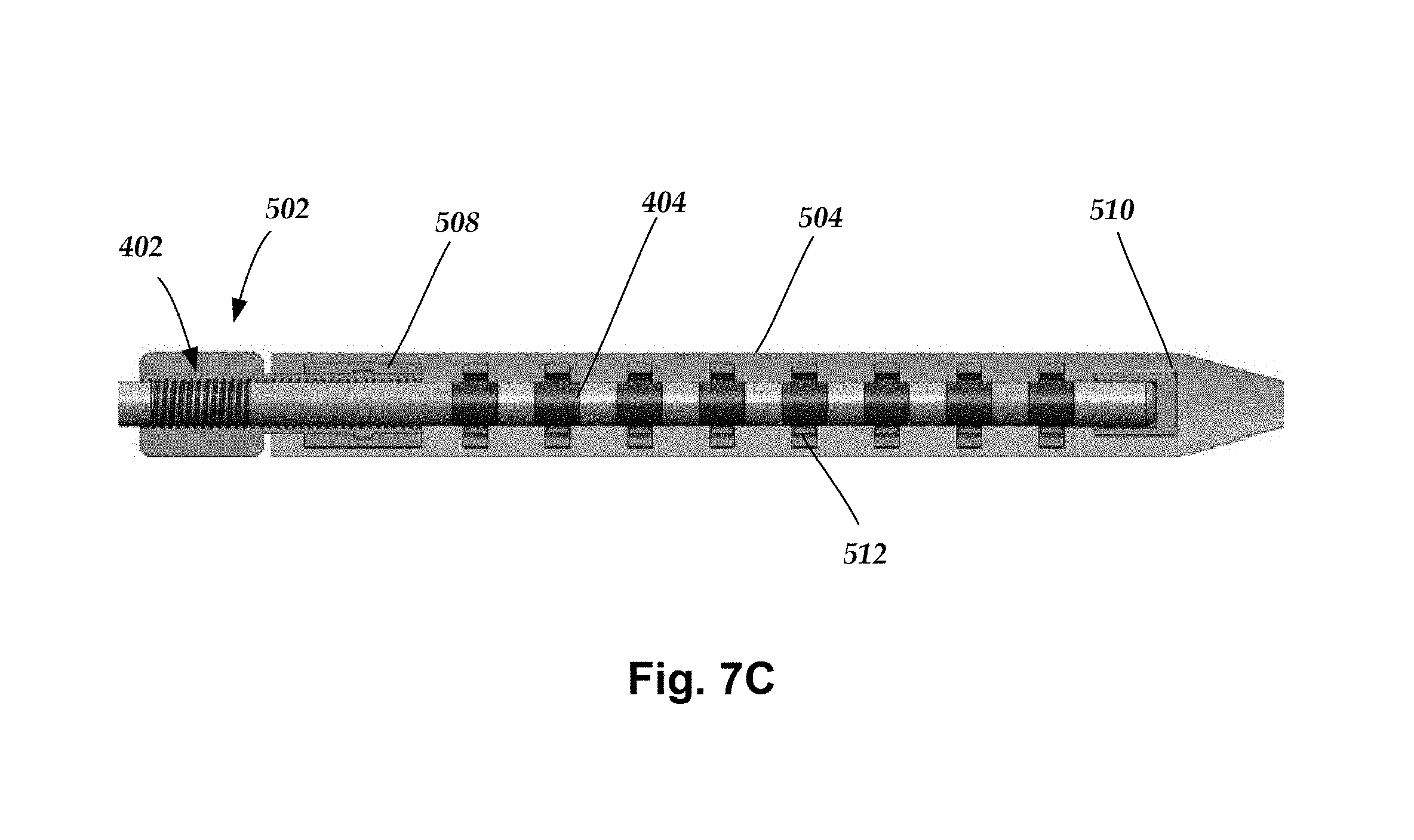
FIG. 7C is a cross-sectional view of the insertable member of FIG. 6 fully inserted into the receiving member of FIG. 6 according to at least some embodiments of the present invention;
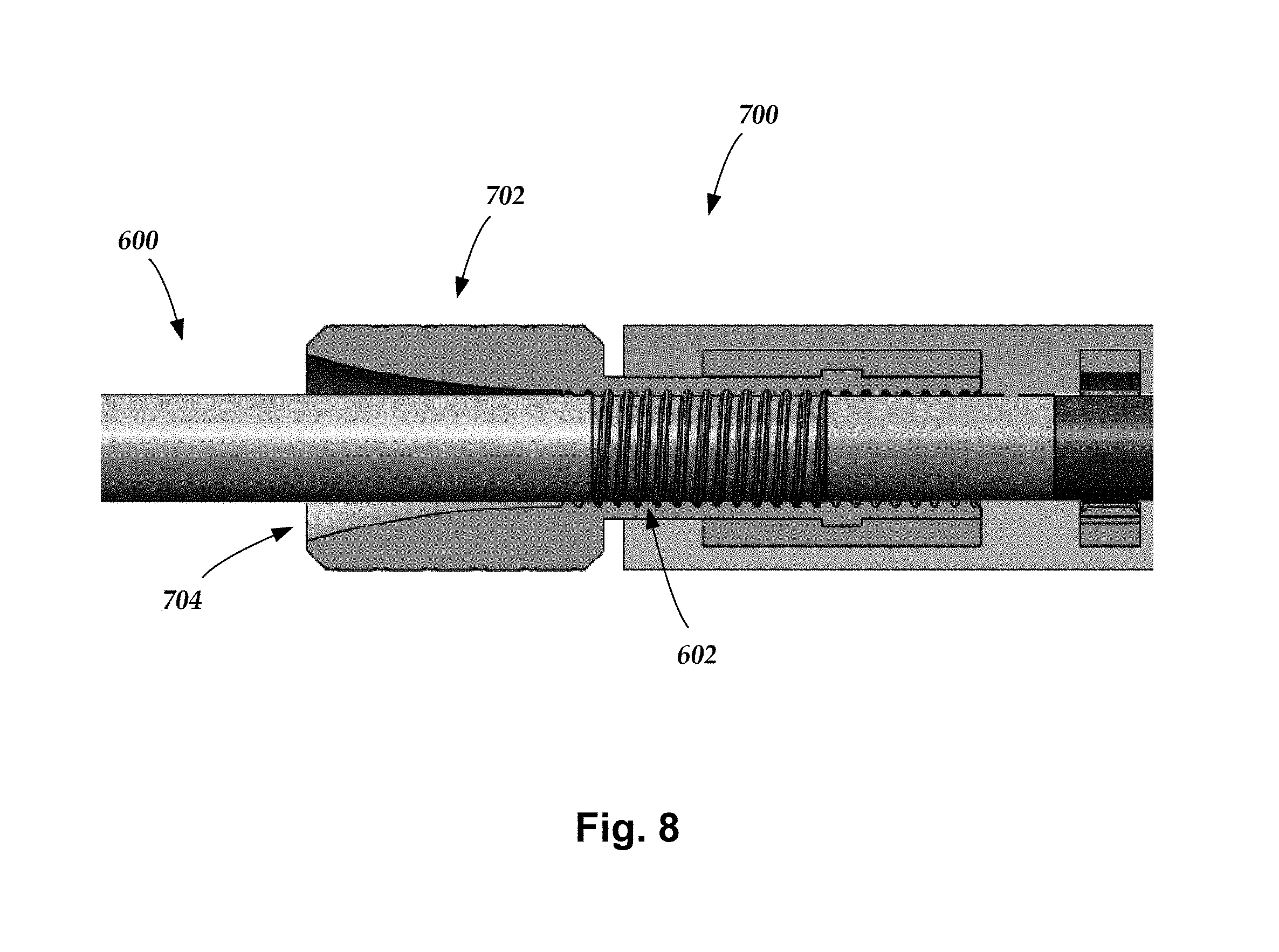
FIG. 8 is a close-up, cross-sectional view of an insertable member inserted into a receiving member having a bellmouth aperture according to at least some embodiments of the present invention;
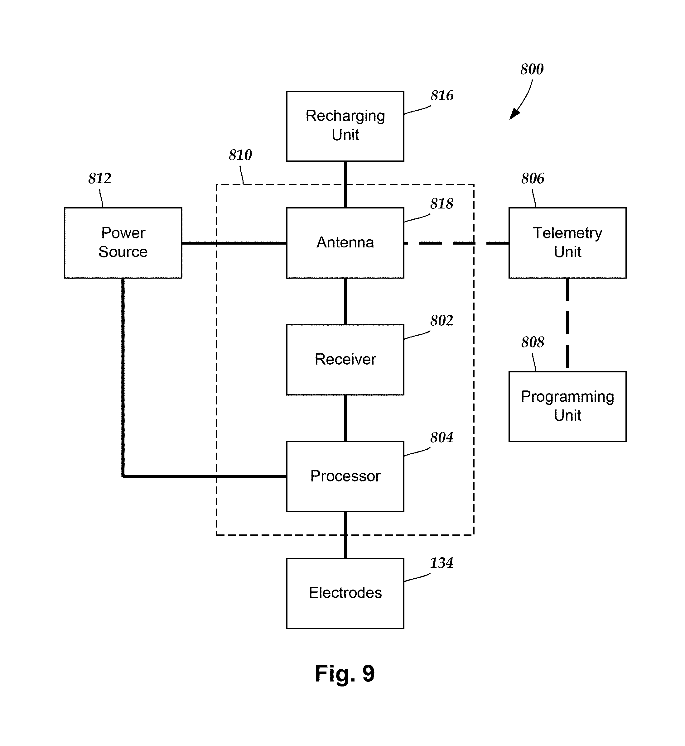
FIG. 9 is a schematic overview of one embodiment of components of a stimulation system, including an electronic subassembly disposed within a control module, according to the invention.
DETAILED DESCRIPTION
The present invention is directed to the area of implantable electrical stimulation systems and methods of making and using the systems. The present invention is also directed to implantable electrical stimulation leads having a threaded connector assembly, as well as methods of making and using the leads and electrical stimulation systems.
Suitable implantable electrical stimulation systems include, but are not limited to, a least one lead with one or more electrodes disposed along a distal end of the lead and one or more terminals disposed along the one or more proximal ends of the lead. Leads include, for example, percutaneous leads, paddle leads, and cuff leads. Examples of electrical stimulation systems with leads are found in, for example, U.S. Pat. Nos. 6,181,969; 6,295,944; 6,391,985; 6,516,227; 6,609,029; 6,609,032; 6,741,892; 7,244,150; 7,450,997; 7,672,734; 7,761,165; 7,783,359; 7,792,590; 7,809,446; 7,949,395; 7,974,706; 8,831,742; 8,688,235; 6,175,710; 6,224,450; 6,271,094; 6,295,944; 6,364,278; and 6,391,985; U.S. Patent Applications Publication Nos. 2007/0150036; 2009/0187222; 2009/0276021; 2010/0076535; 2010/0268298; 2011/0004267; 2011/0078900; 2011/0130817; 2011/0130818; 2011/0238129; 2011/0313500; 2012/0016378; 2012/0046710; 2012/0071949; 2012/0165911; 2012/0197375; 2012/0203316; 2012/0203320; 2012/0203321; 2012/0316615; 2013/0105071; 2011/0005069; 2010/0268298; 2011/0130817; 2011/0130818; 2011/0078900; 2011/0238129; 2011/0313500; 2012/0016378; 2012/0046710; 2012/0165911; 2012/0197375; 2012/0203316; 2012/0203320; and 2012/0203321, all of which are incorporated by reference in their entireties.
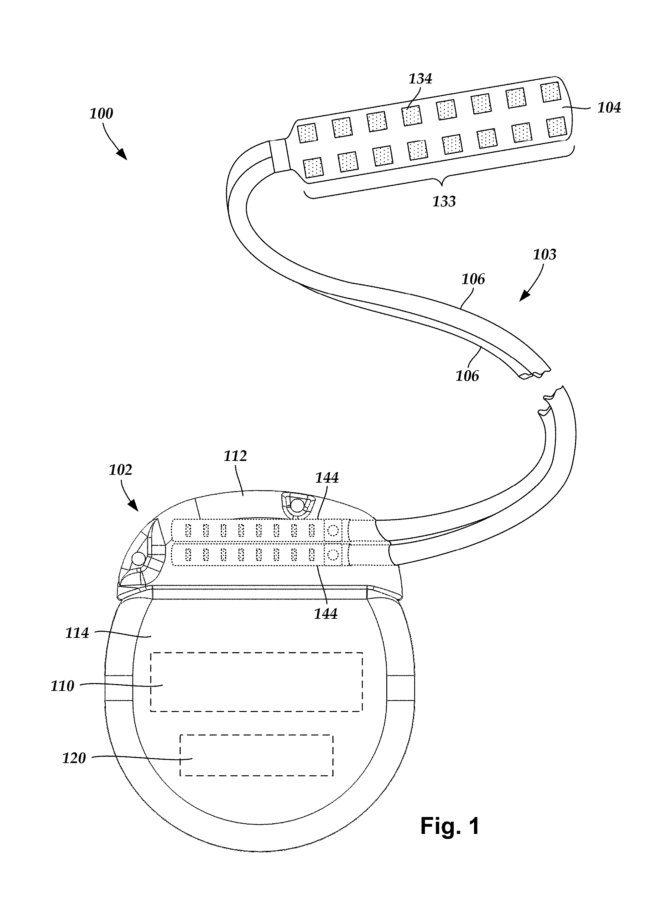
FIG. 1 illustrates schematically one embodiment of an electrical stimulation system 100. The electrical stimulation system includes a control module (e.g., a stimulator or pulse generator) 102 and a lead 103 coupleable to the control module 102. The lead 103 includes a paddle body 104 and one or more lead bodies 106. In FIG. 1, the lead 103 is shown having two lead bodies 106. It will be understood that the lead 103 can include any suitable number of lead bodies including, for example, one, two, three, four, five, six, seven, eight or more lead bodies 106. An array 133 of electrodes, such as electrode 134, is disposed on the paddle body 104, and an array of terminals (e.g., 310 in FIG. 3A-3B) is disposed along each of the one or more lead bodies 106.
It will be understood that the electrical stimulation system can include more, fewer, or different components and can have a variety of different configurations including those configurations disclosed in the electrical stimulation system references cited herein. For example, instead of a paddle body, the electrodes can be disposed in an array at or near the distal end of a lead body forming a percutaneous lead.
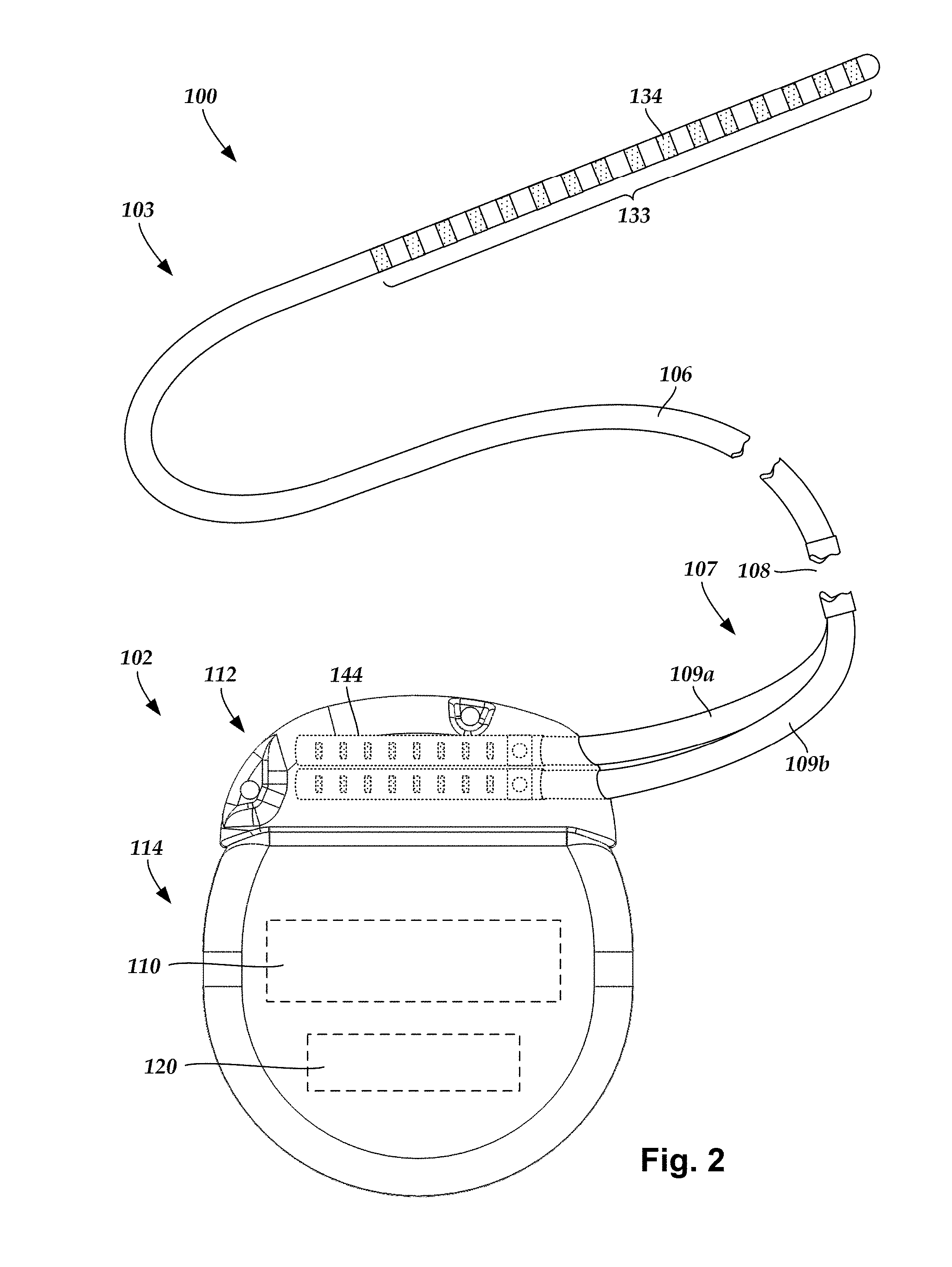
FIG. 2 illustrates schematically another embodiment of the electrical stimulation system 100, where the lead 103 is a percutaneous lead. In FIG. 2, the electrodes 134 are shown disposed along the one or more lead bodies 106. In at least some embodiments, the lead 103 is isodiametric along a longitudinal length of the lead body 106.
The lead 103 can be coupled to the control module 102 in any suitable manner. In FIG. 1, the lead 103 is shown coupling directly to the control module 102. In at least some other embodiments, the lead 103 couples to the control module 102 via one or more intermediate devices (324 in FIG. 3B). For example, in at least some embodiments one or more lead extensions 324 (see e.g., FIG. 3B) can be disposed between the lead 103 and the control module 102 to extend the distance between the lead 103 and the control module 102. Other intermediate devices may be used in addition to, or in lieu of, one or more lead extensions including, for example, a splitter, an adaptor, or the like or combinations thereof. It will be understood that, in the case where the electrical stimulation system 100 includes multiple elongated devices disposed between the lead 103 and the control module 102, the intermediate devices may be configured into any suitable arrangement.
In FIG. 2, the electrical stimulation system 100 is shown having a splitter 107 configured and arranged for facilitating coupling of the lead 103 to the control module 102. The splitter 107 includes a splitter connector 108 configured to couple to a proximal end of the lead 103, and one or more splitter tails 109a and 109b configured and arranged to couple to the control module 102 (or another splitter, a lead extension, an adaptor, or the like).
With reference to FIGS. 1 and 2, the control module 102 typically includes a connector housing 112 and a sealed electronics housing 114. An electronic subassembly 110 and an optional power source 120 are disposed in the electronics housing 114. A control module connector 144 is disposed in the connector housing 112. The control module connector 144 is configured and arranged to make an electrical connection between the lead 103 and the electronic subassembly 110 of the control module 102.
The electrical stimulation system or components of the electrical stimulation system, including the paddle body 104, the one or more of the lead bodies 106, and the control module 102, are typically implanted into the body of a patient. The electrical stimulation system can be used for a variety of applications including, but not limited to deep brain stimulation, neural stimulation, spinal cord stimulation, muscle stimulation, and the like.
The electrodes 134 can be formed using any conductive, biocompatible material. Examples of suitable materials include metals, alloys, conductive polymers, conductive carbon, and the like, as well as combinations thereof. In at least some embodiments, one or more of the electrodes 134 are formed from one or more of: platinum, platinum iridium, palladium, palladium rhodium, or titanium.
Any suitable number of electrodes 134 can be disposed on the lead including, for example, four, five, six, seven, eight, nine, ten, eleven, twelve, fourteen, sixteen, twenty-four, thirty-two, or more electrodes 134. In the case of paddle leads, the electrodes 134 can be disposed on the paddle body 104 in any suitable arrangement. In FIG. 1, the electrodes 134 are arranged into two columns, where each column has eight electrodes 134.
The electrodes of the paddle body 104 (or one or more lead bodies 106) are typically disposed in, or separated by, a non-conductive, biocompatible material such as, for example, silicone, polyurethane, polyetheretherketone ("PEEK"), epoxy, and the like or combinations thereof. The one or more lead bodies 106 and, if applicable, the paddle body 104 may be formed in the desired shape by any process including, for example, molding (including injection molding), casting, and the like. The non-conductive material typically extends from the distal ends of the one or more lead bodies 106 to the proximal end of each of the one or more lead bodies 106.
In the case of paddle leads, the non-conductive material typically extends from the paddle body 104 to the proximal end of each of the one or more lead bodies 106. Additionally, the non-conductive, biocompatible material of the paddle body 104 and the one or more lead bodies 106 may be the same or different. Moreover, the paddle body 104 and the one or more lead bodies 106 may be a unitary structure or can be formed as two separate structures that are permanently or detachably coupled together.
Terminals (e.g., 310 in FIGS. 3A-3B) are typically disposed along the proximal end of the one or more lead bodies 106 of the electrical stimulation system 100 (as well as any splitters, lead extensions, adaptors, or the like) for electrical connection to corresponding connector contacts (e.g., 314 in FIG. 3A). The connector contacts are disposed in connectors (e.g., 144 in FIGS. 1-3B; and 322 FIG. 3B) which, in turn, are disposed on, for example, the control module 102 (or a lead extension, a splitter, an adaptor, or the like). Electrically conductive wires, cables, or the like (not shown) extend from the terminals to the electrodes 134. Typically, one or more electrodes 134 are electrically coupled to each terminal. In at least some embodiments, each terminal is only connected to one electrode 134.
The electrically conductive wires ("conductors") may be embedded in the non-conductive material of the lead body 106 or can be disposed in one or more lumens (not shown) extending along the lead body 106. In some embodiments, there is an individual lumen for each conductor. In other embodiments, two or more conductors extend through a lumen. There may also be one or more lumens (not shown) that open at, or near, the proximal end of the one or more lead bodies 106, for example, for inserting a stylet to facilitate placement of the one or more lead bodies 106 within a body of a patient. Additionally, there may be one or more lumens (not shown) that open at, or near, the distal end of the one or more lead bodies 106, for example, for infusion of drugs or medication into the site of implantation of the one or more lead bodies 106. In at least one embodiment, the one or more lumens are flushed continually, or on a regular basis, with saline, epidural fluid, or the like. In at least some embodiments, the one or more lumens are permanently or removably sealable at the distal end.
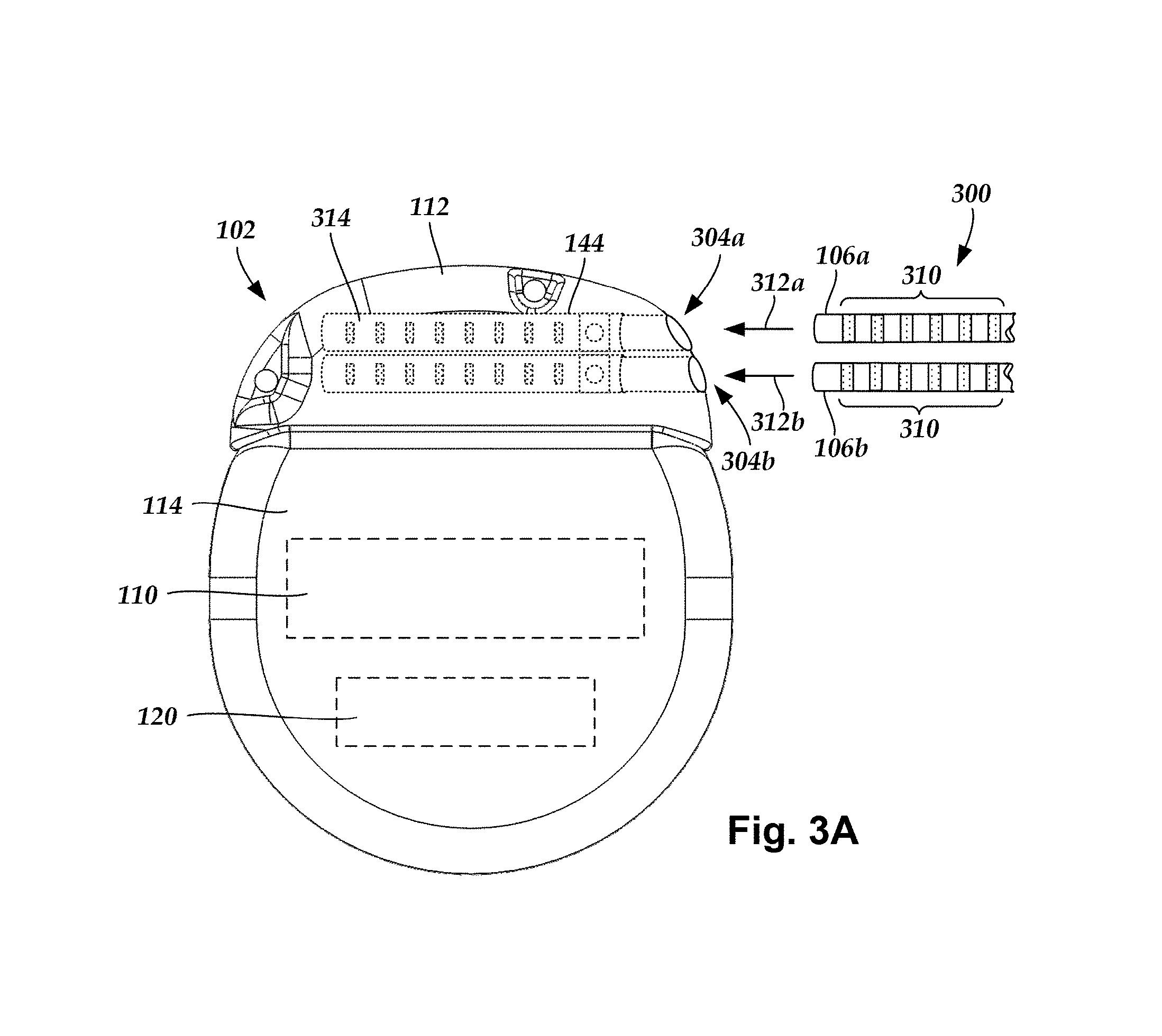
FIG. 3A is a schematic side view of one embodiment of a proximal end of one or more elongated devices 300 configured and arranged for coupling to one embodiment of the control module connector 144. The one or more elongated devices may include, for example, one or more of the lead bodies 106 of FIG. 1, one or more intermediate devices (e.g., a splitter, the lead extension 324 of FIG. 3B, an adaptor, or the like or combinations thereof), or a combination thereof.
The control module connector 144 defines at least one port into which a proximal end of the elongated device 300 can be inserted, as shown by directional arrows 312a and 312b. In FIG. 3A (and in other figures), the connector housing 112 is shown having two ports 304a and 304b. The connector housing 112 can define any suitable number of ports including, for example, one, two, three, four, five, six, seven, eight, or more ports.
The control module connector 144 also includes a plurality of connector contacts, such as connector contact 314, disposed within each port 304a and 304b. When the elongated device 300 is inserted into the ports 304a and 304b, the connector contacts 314 can be aligned with a plurality of terminals 310 disposed along the proximal end(s) of the elongated device(s) 300 to electrically couple the control module 102 to the electrodes (134 of FIG. 1) disposed on the paddle body 104 of the lead 103. Examples of connectors in control modules are found in, for example, U.S. Pat. Nos. 7,244,150 and 8,224,450, which are incorporated by reference.
FIG. 3B is a schematic side view of another embodiment of the electrical stimulation system 100. The electrical stimulation system 100 includes a lead extension 324 that is configured and arranged to couple one or more elongated devices 300 (e.g., one of the lead bodies 106 of FIGS. 1 and 2, the splitter 107 of FIG. 2, an adaptor, another lead extension, or the like or combinations thereof) to the control module 102. In FIG. 3B, the lead extension 324 is shown coupled to a single port 304 defined in the control module connector 144. Additionally, the lead extension 324 is shown configured and arranged to couple to a single elongated device 300. In alternate embodiments, the lead extension 324 is configured and arranged to couple to multiple ports 304 defined in the control module connector 144, or to receive multiple elongated devices 300, or both.
A lead extension connector 322 is disposed on the lead extension 324. In FIG. 3B, the lead extension connector 322 is shown disposed at a distal end 326 of the lead extension 324. The lead extension connector 322 includes a connector housing 328. The connector housing 328 defines at least one port 330 into which terminals 310 of the elongated device 300 can be inserted, as shown by directional arrow 338. The connector housing 328 also includes a plurality of connector contacts, such as connector contacts 340. When the elongated device 300 is inserted into the port 330, the connector contacts 340 disposed in the connector housing 328 can be aligned with the terminals 310 of the elongated device 300 to electrically couple the lead extension 324 to the electrodes (134 of FIGS. 1 and 2) disposed along the lead (103 in FIGS. 1 and 2).
In at least some embodiments, the proximal end of the lead extension 324 is similarly configured and arranged as a proximal end of the lead 103 (or other elongated device 300). The lead extension 324 may include a plurality of electrically conductive wires (not shown) that electrically couple the connector contacts 340 to a proximal end 348 of the lead extension 324 that is opposite to the distal end 326. In at least some embodiments, the conductive wires disposed in the lead extension 324 can be electrically coupled to a plurality of terminals (not shown) disposed along the proximal end 348 of the lead extension 324. In at least some embodiments, the proximal end 348 of the lead extension 324 is configured and arranged for insertion into a connector disposed in another lead extension (or another intermediate device). In other embodiments (and as shown in FIG. 3B), the proximal end 348 of the lead extension 324 is configured and arranged for insertion into the control module connector 144.
In conventional connectors, a neuromodulation lead or lead extension is fixed to a connector using a set block and set screw mechanism. The set block and set screw mechanism generally tends may have a relatively large profile (e.g., spatial envelope) as compared to the profile of the lead or lead extension. The mechanism's relatively large profile can be undesirable in various clinical applications in which a smaller or a reduced profile may be beneficial for patient comfort and clinical efficacy.
As an alternative, at least some embodiments comprise lead having a threaded sleeve coupled to or integrally formed with the lead. A connector assembly configured to receive the threaded sleeve includes a rotational member such as, but not limited to, a female-type fastener like a threaded nut. In at least some embodiments, the rotational member may take the form of a block or cylinder perforated with at least a partially, internally threaded bore so that it can be mated with an externally threaded element (e.g., such as a male-type fastener, a bolt, a threaded rod, a threaded lead, etc.) to connect the lead to the connector assembly. The connector assembly may further include a collar embedded in or integrally formed with a receptacle body of the connector assembly.
FIG. 4A shows a schematic, perspective view of an insertable member 400. For purposes of brevity and clarity, the insertable member 400 is referred to as the lead, but it is understood that at least some embodiments may also apply to a lead extension, a control module, a cable, some combination of thereof, or some other device in which one elongated member requires coupling to another elongated member while achieving an overall low profile for the combination.
The lead 400 includes a sleeve 402 and a terminal array 404. In at least some embodiments, the sleeve 402 includes external threading. FIG. 4B shows a close-up view of the external threading in which a major diameter 406 of the threading is sized to fit through a percutaneous introducer or lumen (not shown).
In at least some embodiment, the sleeve 402 is slid onto the lead 400 and affixed to the lead at a distance 408 from the terminal array 404. In at least some embodiments, the sleeve 402 is made from a rigid material and may mechanically bonded, interference fit, press fit, shrink fit using heat, crimped or otherwise coupled to the lead body 410 of the lead 400. The rigid material may take the form of a metallic material or a plastic material. Preferably, the sleeve 402 is made from a material capable of withstanding the stresses and strains associated with assembling the sleeve onto the lead body, connecting the sleeve to a threaded rotational member, implanting the lead into a patient, and mechanically functioning for at least an operational life of the lead.
Alternatively, the sleeve 402 is integrally disposed with (e.g., molded) or machined into the lead body 410. In such an embodiment, the sleeve 402 is made out of the same material as the lead body 410, which may be a non-conductive, biocompatible material, for example, silicone, polyurethane, polyetheretherketone ("PEEK"), epoxy, and combinations thereof.
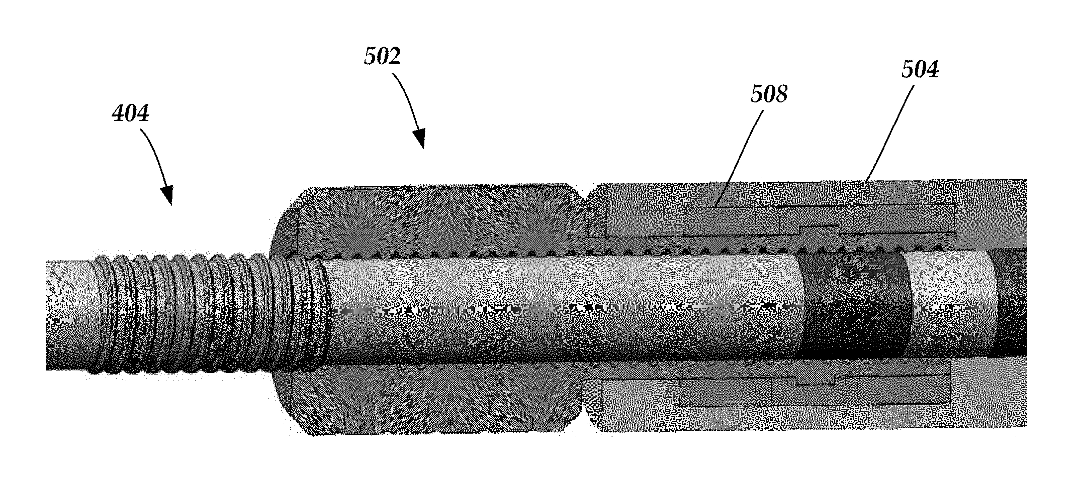
FIG. 5A shows a schematic, perspective view of a connector assembly 500. The connector assembly 500 may be located on either a proximal end portion or a distal end portion of the lead. The connector assembly 500 includes a rotational member 502 that is rotatable independent of a receptacle body 504 of the connector assembly. In at least some embodiments, the receptacle body 504 is made out of the same material as the lead body 410 (FIG. 4A) such as, but not limited to, a non-conductive, biocompatible material, for example, silicone, polyurethane, polyetheretherketone ("PEEK"), epoxy, and combinations thereof.
FIG. 5B shows a longitudinal, cross-sectional view of the connector assembly 500. In the illustrated embodiment, the receptacle body 504 includes an annular member or collar 508 embedded into and fixed to the receptacle body 504 and a plurality of connector contacts 512. In at least some embodiments and after connecting the lead 400 with the connector assembly 500, each connector contact 512 aligns with and electrically communicates with each respective terminal comprising the terminal array 404 (FIG. 4A). Examples of connector assemblies for electrical stimulation systems with leads are found in, for example, U.S. Pat. Nos. 8,849,396; 7,244,150; 8,600,507; 8,897,876; 8,682,439; U.S. Patent Applications Publication Nos. 2012/0053646; 2014/0148885; 2015/0209575; 2016/0059019; and U.S. Patent Provisional Patent Application Nos. 62/193,472; 62/216,594; 62/259,463; and 62/278,667, all of which are incorporated by reference in their entireties.
Optionally, the receptacle body 504 further includes an end stop feature 510 embedded in or integrally disposed (e.g., molded) in the receptacle body 504. It is appreciated that the collar 508, the end stop feature 510, or both may be integrally formed with the receptacle body 504, and thus of the same material as the receptacle body, it is preferable that the collar 508, the end stop feature 510 or both be made from a more rigid material as compared to the receptacle body 504. A more rigid material for the collar 508 would permit the collar 508 to have a durable contact and bearing surface that is more suitable for rotational contact during insertion of the lead into the connector assembly. Similarly, the more rigid material for the end stop feature 510 would provide for a more durable and robust contact and bearing surface when the lead is inserted into the connector assembly.
Referring briefly back to FIG. 5A and in at least some embodiments, the rotational member 502 may include a textured surface that may be integrally formed with or machined onto the rotational member 502. In the illustrated embodiment, the textured surface takes the form of a cross-hatched, grippable pattern to improve one's grip when turning the rotational member 502.
FIG. 5C shows a cross-sectional, close-up view of the rotational member 502 and the collar 508. The rotational member 502 includes a head portion 514 and an elongated portion 516. A bearing interface 518 separates the elongated portion 516 from the collar 508 and permits the rotational member 502 to rotate freely with respect to at least the receptacle body 504, the collar 508, end stop feature 510, and the connector contacts 512 (FIGS. 5A and 5B). The elongated portion 516 includes a stop member 522 that extends radially from at least a portion of the elongated portion 516. The stop member 522 engages with the collar 508 to reduce or prevent longitudinal movement or removal of the rotational member 502 relative to the receptacle body 504.
In the illustrated embodiment, both the head portion 514 and the elongated portion 516 of the rotational member 502 have internal threading 520 that extend the length of the rotational member 502, and therefore an insertion depth of the lead into the connector assembly is determined by the location of the end stop feature 510 (FIG. 5B). In at least some embodiments, the rotational member 502 takes the form of a threaded, locking nut.
FIG. 6 shows a schematic, perspective view of the lead 400 about to be inserted into the connector assembly 500. Because the rotational member 502 freely spins relative to the receptacle body 504, the collar 508, end stop feature 510, and the connector contacts 512 (FIGS. 5A and 5B), rotation of the rotational member 502 after engagement with the sleeve 402 pulls or urges the lead 400 into the connector assembly 500. The receptacle body and rotational member are configured and arranged to receive a portion of a lead or a lead extension through a connector assembly lumen 524.
FIG. 7A shows a schematic, perspective, close-up, cross-sectional view of the lead 400 partially inserted into the connector assembly 500 in that only a portion of the sleeve 402 is received into the rotational member 502. FIGS. 7B and 7C show the lead 400 fully inserted into the connector assembly 500 such that (1) the sleeve 402 is fully received into the rotational member 502; (2) the respective terminals of the terminal array 404 are respectively aligned and in electrical communication with the connector contacts 512; and (3) the longitudinal insertion depth of the lead 400 is determined and halted by the end stop feature 510.
FIG. 8 shows a schematic, perspective, close-up, cross-sectional view of a lead 600 fully inserted into a connector assembly 700. A head portion of a rotational member 702 includes a flared (e.g., bellmouth) opening or aperture 704 for receiving the lead 600. In at least some embodiments, the flared aperture 704 is configured to provide an amount of radial or lateral deflection for the lead 600 relative to the head portion of the rotational member 702. Allowing the lead to radially or laterally deflect may advantageously provide strain relief in that lead migration or connector assembly migration would not cause the lead to be pressed against an edge of the connector assembly, which could kink or otherwise damage the lead.
In at least some of the aforementioned embodiments, the threading of the sleeve extended along a full length of the rotational member. Alternatively, portions of the rotational member may be unthreaded. By way of example, the internal threading of the elongated portion of the rotational member may stop at a predetermined depth that is less than a length of the collar. In such an embodiment, it would only be possible to thread the lead into the connector assembly to where the threading ended. Accordingly, the partially threaded elongated portion could operate as a mechanical stop to determine the insertion depth and stop the advancement of the lead into the connector assembly without employing an end stop feature.
In at least some embodiments, the connector assembly can be water resistant or hermetically sealed.
FIG. 9 is a schematic overview of one embodiment of components of an electrical stimulation system 800 including an electronic subassembly 810 disposed within a control module. It will be understood that the electrical stimulation system can include more, fewer, or different components and can have a variety of different configurations including those configurations disclosed in the stimulator references cited herein.
Some of the components (for example, a power source 812, an antenna 818, a receiver 802, and a processor 804) of the electrical stimulation system can be positioned on one or more circuit boards or similar carriers within a sealed housing of an implantable pulse generator, if desired. Any power source 812 can be used including, for example, a battery such as a primary battery or a rechargeable battery. Examples of other power sources include super capacitors, nuclear or atomic batteries, mechanical resonators, infrared collectors, thermally-powered energy sources, flexural powered energy sources, bioenergy power sources, fuel cells, bioelectric cells, osmotic pressure pumps, and the like including the power sources described in U.S. Pat. No. 7,437,193, incorporated herein by reference.
As another alternative, power can be supplied by an external power source through inductive coupling via the optional antenna 818 or a secondary antenna. The external power source can be in a device that is mounted on the skin of the user or in a unit that is provided near the user on a permanent or periodic basis.
If the power source 812 is a rechargeable battery, the battery may be recharged using the optional antenna 818, if desired. Power can be provided to the battery for recharging by inductively coupling the battery through the antenna to a recharging unit 816 external to the user. Examples of such arrangements can be found in the references identified above.
In one embodiment, electrical current is emitted by the electrodes 134 on the paddle or lead body to stimulate nerve fibers, muscle fibers, or other body tissues near the electrical stimulation system. The processor 804 is generally included to control the timing and electrical characteristics of the electrical stimulation system. For example, the processor 804 can, if desired, control one or more of the timing, frequency, strength, duration, and waveform of the pulses. In addition, the processor 804 can select which electrodes can be used to provide stimulation, if desired. In some embodiments, the processor 804 selects which electrode(s) are cathodes and which electrode(s) are anodes. In some embodiments, the processor 804 is used to identify which electrodes provide the most useful stimulation of the desired tissue.
Any processor can be used and can be as simple as an electronic device that, for example, produces pulses at a regular interval or the processor can be capable of receiving and interpreting instructions from an external programming unit 808 that, for example, allows modification of pulse characteristics. In the illustrated embodiment, the processor 804 is coupled to a receiver 802 which, in turn, is coupled to the optional antenna 818. This allows the processor 804 to receive instructions from an external source to, for example, direct the pulse characteristics and the selection of electrodes, if desired.
In one embodiment, the antenna 818 is capable of receiving signals (e.g., RF signals) from an external telemetry unit 806 which is programmed by the programming unit 808. The programming unit 808 can be external to, or part of, the telemetry unit 806. The telemetry unit 806 can be a device that is worn on the skin of the user or can be carried by the user and can have a form similar to a pager, cellular phone, or remote control, if desired. As another alternative, the telemetry unit 806 may not be worn or carried by the user but may only be available at a home station or at a clinician's office. The programming unit 808 can be any unit that can provide information to the telemetry unit 806 for transmission to the electrical stimulation system 800. The programming unit 808 can be part of the telemetry unit 806 or can provide signals or information to the telemetry unit 806 via a wireless or wired connection. One example of a suitable programming unit is a computer operated by the user or clinician to send signals to the telemetry unit 806.
The signals sent to the processor 804 via the antenna 818 and the receiver 802 can be used to modify or otherwise direct the operation of the electrical stimulation system. For example, the signals may be used to modify the pulses of the electrical stimulation system such as modifying one or more of pulse duration, pulse frequency, pulse waveform, and pulse strength. The signals may also direct the electrical stimulation system 800 to cease operation, to start operation, to start charging the battery, or to stop charging the battery. In other embodiments, the stimulation system does not include the antenna 818 or receiver 802 and the processor 804 operates as programmed.
Optionally, the electrical stimulation system 800 may include a transmitter (not shown) coupled to the processor 804 and the antenna 818 for transmitting signals back to the telemetry unit 806 or another unit capable of receiving the signals. For example, the electrical stimulation system 800 may transmit signals indicating whether the electrical stimulation system 800 is operating properly or not or indicating when the battery needs to be charged or the level of charge remaining in the battery. The processor 804 may also be capable of transmitting information about the pulse characteristics so that a user or clinician can determine or verify the characteristics.
The above specification provides a description of the structure, manufacture, and use of the invention. Since many embodiments of the invention can be made without departing from the spirit and scope of the invention, the invention also resides in the claims hereinafter appended.
* * * * *
D00000
D00001
D00002
D00003
D00004
D00005
D00006
D00007
D00008
D00009
D00010
D00011
D00012
XML
uspto.report is an independent third-party trademark research tool that is not affiliated, endorsed, or sponsored by the United States Patent and Trademark Office (USPTO) or any other governmental organization. The information provided by uspto.report is based on publicly available data at the time of writing and is intended for informational purposes only.
While we strive to provide accurate and up-to-date information, we do not guarantee the accuracy, completeness, reliability, or suitability of the information displayed on this site. The use of this site is at your own risk. Any reliance you place on such information is therefore strictly at your own risk.
All official trademark data, including owner information, should be verified by visiting the official USPTO website at www.uspto.gov. This site is not intended to replace professional legal advice and should not be used as a substitute for consulting with a legal professional who is knowledgeable about trademark law.