Lateral mass fixation system
McCormack , et al. Feb
U.S. patent number 10,201,375 [Application Number 14/723,410] was granted by the patent office on 2019-02-12 for lateral mass fixation system. This patent grant is currently assigned to PROVIDENCE MEDICAL TECHNOLOGY, INC.. The grantee listed for this patent is Edward Liou, Bruce M. McCormack, Christopher U. Phan, Shigeru Tanaka. Invention is credited to Edward Liou, Bruce M. McCormack, Christopher U. Phan, Shigeru Tanaka.


View All Diagrams
| United States Patent | 10,201,375 |
| McCormack , et al. | February 12, 2019 |
Lateral mass fixation system
Abstract
A device for accessing and guiding at least one fixation device to a spine may include a distal portion configured to fit in a facet of the spine and a proximal portion extending from the distal portion. The proximal portion may be detachable from the distal portion and may be hollow or solid. A system for accessing and guiding at least one fixation device to a spine may include a distal portion configured to fit in a facet of the spine, a proximal portion extending from the distal portion, and a slidable guide device for sliding over the facet guide device to guide at least one instrument to the spine.
| Inventors: | McCormack; Bruce M. (San Francisco, CA), Liou; Edward (Pleasanton, CA), Tanaka; Shigeru (Half Moon Bay, CA), Phan; Christopher U. (Dublin, CA) | ||||||||||
|---|---|---|---|---|---|---|---|---|---|---|---|
| Applicant: |
|
||||||||||
| Assignee: | PROVIDENCE MEDICAL TECHNOLOGY,
INC. (Pleasanton, CA) |
||||||||||
| Family ID: | 54699745 | ||||||||||
| Appl. No.: | 14/723,410 | ||||||||||
| Filed: | May 27, 2015 |
Prior Publication Data
| Document Identifier | Publication Date | |
|---|---|---|
| US 20150342649 A1 | Dec 3, 2015 | |
Related U.S. Patent Documents
| Application Number | Filing Date | Patent Number | Issue Date | ||
|---|---|---|---|---|---|
| 62004143 | May 28, 2014 | ||||
| Current U.S. Class: | 1/1 |
| Current CPC Class: | A61B 17/7032 (20130101); A61B 17/1671 (20130101); A61B 17/7082 (20130101); A61B 17/7011 (20130101); A61B 17/1757 (20130101); A61B 17/1604 (20130101); A61B 17/7064 (20130101) |
| Current International Class: | A61B 17/70 (20060101); A61B 17/16 (20060101); A61B 17/17 (20060101) |
References Cited [Referenced By]
U.S. Patent Documents
| 1934962 | November 1933 | Barry |
| 2708376 | May 1955 | Booth |
| 2984241 | May 1961 | Carlson |
| 4479491 | October 1984 | Martin |
| 4530355 | July 1985 | Griggs |
| 4604995 | August 1986 | Stephens et al. |
| 4772287 | September 1988 | Ray et al. |
| 4877020 | October 1989 | Vich |
| 4878915 | November 1989 | Brantigan |
| 5015247 | May 1991 | Michelson |
| 5026373 | June 1991 | Ray et al. |
| 5100405 | March 1992 | McLaren |
| 5135528 | August 1992 | Winston |
| 5236460 | August 1993 | Barber |
| 5484437 | January 1996 | Michelson |
| 5489307 | February 1996 | Kuslich et al. |
| 5505732 | April 1996 | Michelson |
| 5527312 | June 1996 | Ray |
| 5549679 | August 1996 | Kuslich et al. |
| 5554191 | September 1996 | Lahille et al. |
| 5571191 | November 1996 | Fitz |
| 5584832 | December 1996 | Schlapfer et al. |
| 5593409 | January 1997 | Michelson |
| 5632747 | May 1997 | Scarborough et al. |
| 5649945 | July 1997 | Ray et al. |
| 5653763 | August 1997 | Errico et al. |
| 5665122 | September 1997 | Kambin |
| 5674295 | October 1997 | Ray et al. |
| 5720748 | February 1998 | Kuslich et al. |
| 5741253 | April 1998 | Michelson |
| 5772661 | June 1998 | Michelson |
| 5792044 | August 1998 | Foley et al. |
| 5797909 | August 1998 | Michelson |
| 5836948 | November 1998 | Zucherman et al. |
| 5879353 | March 1999 | Terry |
| 5885299 | March 1999 | Winslow et al. |
| 5891147 | April 1999 | Moskovitz |
| 5895426 | April 1999 | Scarborough et al. |
| 5899908 | May 1999 | Kuslich et al. |
| 5928238 | July 1999 | Scarborough et al. |
| 5953820 | September 1999 | Vasudeva |
| 5961522 | October 1999 | Mehdizadeh |
| 5976146 | November 1999 | Ogawa et al. |
| 6008433 | December 1999 | Stone |
| 6033405 | March 2000 | Winslow et al. |
| 6045580 | April 2000 | Scarborough et al. |
| 6063088 | May 2000 | Winslow |
| RE36758 | June 2000 | Fitz |
| 6080155 | June 2000 | Michelson |
| 6090143 | July 2000 | Meriwether et al. |
| 6096038 | August 2000 | Michelson |
| 6099531 | August 2000 | Bonutti |
| 6102950 | August 2000 | Vaccaro |
| 6113602 | September 2000 | Sand |
| 6149650 | November 2000 | Michelson |
| RE37005 | December 2000 | Michelson et al. |
| 6159245 | December 2000 | Meriwether et al. |
| 6176882 | January 2001 | Biedermann et al. |
| 6179873 | January 2001 | Zientek |
| 6190388 | February 2001 | Michelson et al. |
| 6190414 | February 2001 | Young et al. |
| 6193757 | February 2001 | Foley et al. |
| 6210412 | April 2001 | Michelson |
| RE37161 | May 2001 | Michelson et al. |
| 6224595 | May 2001 | Michelson |
| 6224607 | May 2001 | Michelson |
| 6224630 | May 2001 | Bao et al. |
| 6245108 | June 2001 | Biscup |
| 6248110 | June 2001 | Reiley et al. |
| D444878 | July 2001 | Walter |
| D445188 | July 2001 | Walter |
| 6264656 | July 2001 | Michelson |
| 6267763 | July 2001 | Castro |
| 6270498 | August 2001 | Michelson |
| 6283966 | September 2001 | Boufburg |
| 6315795 | November 2001 | Scarborough et al. |
| 6325827 | December 2001 | Lin |
| 6371984 | April 2002 | Van Dyke et al. |
| 6371988 | April 2002 | Pafford et al. |
| 6402784 | June 2002 | Wardlaw |
| 6423063 | July 2002 | Bonutti |
| 6423083 | July 2002 | Reiley et al. |
| 6425919 | July 2002 | Lambrecht |
| 6436098 | August 2002 | Michelson |
| 6436142 | August 2002 | Paes et al. |
| 6443988 | September 2002 | Felt et al. |
| 6451023 | September 2002 | Salazar et al. |
| 6454807 | September 2002 | Jackson |
| 6478796 | November 2002 | Zucherman et al. |
| 6500206 | December 2002 | Bryan |
| 6514256 | February 2003 | Zucherman et al. |
| 6530955 | March 2003 | Boyle et al. |
| 6558390 | May 2003 | Cragg |
| 6565574 | May 2003 | Michelson |
| 6565605 | May 2003 | Fallin et al. |
| 6569186 | May 2003 | Winters et al. |
| 6575919 | June 2003 | Reiley et al. |
| 6575979 | June 2003 | Cragg |
| 6579319 | June 2003 | Goble et al. |
| 6582432 | June 2003 | Michelson |
| 6607530 | August 2003 | Carl et al. |
| 6610091 | August 2003 | Reiley |
| 6626905 | September 2003 | Schmiel et al. |
| 6632235 | October 2003 | Weikel et al. |
| 6635060 | October 2003 | Hanson et al. |
| 6641582 | November 2003 | Hanson et al. |
| 6648893 | November 2003 | Dudasik |
| 6652584 | November 2003 | Michelson |
| 6663647 | December 2003 | Reiley et al. |
| 6666866 | December 2003 | Martz et al. |
| 6679886 | January 2004 | Weikel et al. |
| 6682535 | January 2004 | Hoogland |
| 6685742 | February 2004 | Jackson |
| 6709458 | March 2004 | Michelson |
| 6712853 | March 2004 | Kuslich |
| 6719773 | April 2004 | Boucher et al. |
| 6723095 | April 2004 | Hammerslag |
| 6733534 | May 2004 | Sherman |
| 6740093 | May 2004 | Hochschuler et al. |
| 6751875 | June 2004 | Jones |
| 6770074 | August 2004 | Michelson |
| 6793679 | September 2004 | Michelson |
| 6805715 | October 2004 | Reuter et al. |
| 6808537 | October 2004 | Michelson |
| 6823871 | November 2004 | Schmieding |
| 6840941 | January 2005 | Rogers et al. |
| 6851430 | February 2005 | Tsou |
| 6875213 | April 2005 | Michelson |
| 6899719 | May 2005 | Reiley et al. |
| 6921403 | July 2005 | Cragg et al. |
| 6923813 | August 2005 | Phillips et al. |
| 6958077 | October 2005 | Suddaby |
| 6962606 | November 2005 | Michelson |
| 6964686 | November 2005 | Gordon |
| 6966930 | November 2005 | Arnin et al. |
| 6972035 | December 2005 | Michelson |
| 6974478 | December 2005 | Reiley et al. |
| 6979333 | December 2005 | Hammerslag |
| 6986772 | January 2006 | Michelson |
| 7001385 | February 2006 | Bonutti |
| 7008453 | March 2006 | Michelson |
| 7033362 | April 2006 | McGahan et al. |
| 7033392 | April 2006 | Schmiel et al. |
| 7033394 | April 2006 | Michelson |
| 7066961 | June 2006 | Michelson |
| D524443 | July 2006 | Blain |
| 7083623 | August 2006 | Michelson |
| 7090698 | August 2006 | Fallin et al. |
| 7096972 | August 2006 | Orozco, Jr. |
| 7101398 | September 2006 | Dooris et al. |
| 7115128 | October 2006 | Michelson |
| 7118598 | October 2006 | Michelson |
| 7128760 | October 2006 | Michelson |
| 7156877 | January 2007 | Lotz et al. |
| 7166110 | January 2007 | Yundt |
| 7175023 | February 2007 | Martin |
| 7179263 | February 2007 | Zdeblick et al. |
| 7207991 | April 2007 | Michelson |
| D541940 | May 2007 | Blain |
| 7220280 | May 2007 | Kast et al. |
| 7264622 | September 2007 | Michelson |
| 7273498 | September 2007 | Bianchi et al. |
| 7288093 | October 2007 | Michelson |
| 7291149 | November 2007 | Michelson |
| 7300440 | November 2007 | Zdeblick et al. |
| 7326211 | February 2008 | Padget et al. |
| 7326214 | February 2008 | Michelson |
| 7371238 | May 2008 | Soboleski et al. |
| 7399303 | July 2008 | Michelson |
| 7410501 | August 2008 | Michelson |
| 7431722 | October 2008 | Michelson |
| 7445636 | November 2008 | Michelson |
| 7452359 | November 2008 | Michelson |
| 7452369 | November 2008 | Barry |
| 7465304 | December 2008 | Haufe et al. |
| 7476226 | January 2009 | Weikel et al. |
| 7476251 | January 2009 | Zucherman et al. |
| 7479160 | January 2009 | Branch et al. |
| 7491205 | February 2009 | Michelson |
| 7500992 | March 2009 | Li |
| 7517358 | April 2009 | Peterson |
| 7524333 | April 2009 | Lambrecht et al. |
| 7569054 | August 2009 | Michelson |
| 7569057 | August 2009 | Liu et al. |
| 7580743 | August 2009 | Bourlion et al. |
| 7591851 | September 2009 | Winslow et al. |
| 7601170 | October 2009 | Winslow et al. |
| 7608077 | October 2009 | Cragg et al. |
| 7608107 | October 2009 | Michelson |
| 7615079 | November 2009 | Flickinger et al. |
| 7618451 | November 2009 | Berez et al. |
| 7632291 | December 2009 | Stephens et al. |
| 7641664 | January 2010 | Pagano |
| 7648523 | January 2010 | Mirkovic et al. |
| 7655027 | February 2010 | Michelson |
| 7655043 | February 2010 | Peterman et al. |
| 7662173 | February 2010 | Cragg et al. |
| D611147 | March 2010 | Hanson et al. |
| 7682378 | March 2010 | Truckai et al. |
| 7686805 | March 2010 | Michelson |
| 7686807 | March 2010 | Padget et al. |
| 7699878 | April 2010 | Pavlov et al. |
| D615653 | May 2010 | Horton |
| 7708761 | May 2010 | Petersen |
| 7722619 | May 2010 | Michelson |
| D619719 | July 2010 | Pannu |
| 7763024 | July 2010 | Bertagnoli et al. |
| 7763050 | July 2010 | Winslow et al. |
| 7776090 | August 2010 | Winslow et al. |
| D623748 | September 2010 | Horton et al. |
| D623749 | September 2010 | Horton et al. |
| 7789898 | September 2010 | Peterman |
| D627468 | November 2010 | Richter et al. |
| 7824431 | November 2010 | McCormack |
| 7837713 | November 2010 | Peterson |
| 7846183 | December 2010 | Blain |
| 7846184 | December 2010 | Sasso et al. |
| 7850733 | December 2010 | Baynham et al. |
| 7862589 | January 2011 | Thramann |
| 7867277 | January 2011 | Tohmeh |
| D631967 | February 2011 | Horton |
| 7879098 | February 2011 | Simmons, Jr. |
| 7887565 | February 2011 | Michelson |
| 7892261 | February 2011 | Bonutti |
| 7892286 | February 2011 | Michelson |
| 7896803 | March 2011 | Schara et al. |
| 7896903 | March 2011 | Link |
| 7901439 | March 2011 | Horton |
| 7914530 | March 2011 | Michelson |
| 7918891 | April 2011 | Curran et al. |
| 7922729 | April 2011 | Michelson |
| 7922766 | April 2011 | Grob et al. |
| 7935136 | May 2011 | Alamin et al. |
| 7938857 | May 2011 | Krueger et al. |
| 7988712 | August 2011 | Hale et al. |
| 7988714 | August 2011 | Puekert et al. |
| 7998174 | August 2011 | Malandain et al. |
| 8007534 | August 2011 | Michelson |
| 8029540 | October 2011 | Winslow et al. |
| 8043334 | October 2011 | Fisher et al. |
| 8052728 | November 2011 | Hestad |
| 8062303 | November 2011 | Berry et al. |
| 8066705 | November 2011 | Michelson |
| D650481 | December 2011 | Gottlieb et al. |
| 8097034 | January 2012 | Michelson |
| 8100944 | January 2012 | Lauryssen et al. |
| D653757 | February 2012 | Binder |
| 8114158 | February 2012 | Carl et al. |
| 8118838 | February 2012 | Winslow et al. |
| 8128660 | March 2012 | Mitchel et al. |
| 8133261 | March 2012 | Fisher et al. |
| 8142503 | March 2012 | Malone |
| 8147553 | April 2012 | Vresilovic et al. |
| 8162981 | April 2012 | Vestgaarden |
| 8172877 | May 2012 | Winslow et al. |
| 8177872 | May 2012 | Nelson et al. |
| 8197513 | June 2012 | Fisher et al. |
| 8206418 | June 2012 | Triplett et al. |
| 8267966 | September 2012 | McCormack et al. |
| D674900 | January 2013 | Janice et al. |
| 8348979 | January 2013 | McCormack |
| 8361152 | January 2013 | McCormack et al. |
| 8366748 | February 2013 | Kleiner |
| D677791 | March 2013 | Danacioglu et al. |
| 8394107 | March 2013 | Fanger et al. |
| 8394129 | March 2013 | Morgenstern et al. |
| D681205 | April 2013 | Farris et al. |
| 8425558 | April 2013 | McCormack et al. |
| 8512347 | August 2013 | McCormack et al. |
| 8523908 | September 2013 | Malone |
| 8623054 | January 2014 | McCormack et al. |
| 8668722 | March 2014 | Pavlov et al. |
| 8753347 | June 2014 | McCormack et al. |
| 8764755 | July 2014 | Michelson |
| 8828062 | September 2014 | McCormack et al. |
| 8834530 | September 2014 | McCormack |
| 8845727 | September 2014 | Gottlieb et al. |
| 8870882 | October 2014 | Kleiner |
| D723690 | March 2015 | McCormack et al. |
| D723691 | March 2015 | McCormack et al. |
| 8998905 | April 2015 | Marik et al. |
| 9011492 | April 2015 | McCormack et al. |
| D732667 | June 2015 | McCormack et al. |
| D745156 | December 2015 | McCormack et al. |
| 9211198 | December 2015 | Michelson |
| 9220608 | December 2015 | McKay |
| D750249 | February 2016 | Grimberg, Jr. et al. |
| 9271765 | March 2016 | Blain |
| 9333086 | May 2016 | McCormack et al. |
| 9381049 | July 2016 | McCormack et al. |
| 9427264 | August 2016 | Kleiner et al. |
| 9504583 | November 2016 | Blain |
| 9717403 | August 2017 | Kleiner et al. |
| 2001/0004710 | June 2001 | Felt et al. |
| 2001/0047208 | November 2001 | Michelson |
| 2002/0026195 | February 2002 | Layne et al. |
| 2002/0107519 | August 2002 | Dixon et al. |
| 2002/0143343 | October 2002 | Castro |
| 2002/0147496 | October 2002 | Belef et al. |
| 2002/0147497 | October 2002 | Belef et al. |
| 2002/0165612 | November 2002 | Gerber et al. |
| 2002/0169471 | November 2002 | Ferdinand |
| 2003/0023312 | January 2003 | Thalgott |
| 2003/0028251 | February 2003 | Mathews |
| 2003/0032962 | February 2003 | McGahan et al. |
| 2003/0033017 | February 2003 | Lotz et al. |
| 2003/0105526 | June 2003 | Bryant et al. |
| 2003/0109928 | June 2003 | Pasquet et al. |
| 2003/0139816 | July 2003 | Michelson |
| 2003/0144737 | July 2003 | Sherman |
| 2003/0158553 | August 2003 | Michelson |
| 2003/0225416 | December 2003 | Bonvallet et al. |
| 2004/0059337 | March 2004 | Hanson et al. |
| 2004/0073217 | April 2004 | Michelson |
| 2004/0087948 | May 2004 | Suddaby |
| 2004/0087956 | May 2004 | Weikel et al. |
| 2004/0106999 | June 2004 | Mathews |
| 2004/0133277 | July 2004 | Michelson |
| 2004/0133280 | July 2004 | Trieu |
| 2004/0162562 | August 2004 | Martz |
| 2004/0215344 | October 2004 | Hochshculer et al. |
| 2005/0010294 | January 2005 | Michelson |
| 2005/0015149 | January 2005 | Michelson |
| 2005/0027358 | February 2005 | Suddaby |
| 2005/0033432 | February 2005 | Gordon et al. |
| 2005/0049705 | March 2005 | Hale et al. |
| 2005/0055096 | March 2005 | Serhan et al. |
| 2005/0065518 | March 2005 | Michelson |
| 2005/0065519 | March 2005 | Michelson |
| 2005/0065608 | March 2005 | Michelson |
| 2005/0065609 | March 2005 | Wardlaw |
| 2005/0080422 | April 2005 | Otte et al. |
| 2005/0090829 | April 2005 | Martz et al. |
| 2005/0090901 | April 2005 | Studer |
| 2005/0119680 | June 2005 | Dykes |
| 2005/0124993 | June 2005 | Chappuis |
| 2005/0159650 | July 2005 | Raymond et al. |
| 2005/0159746 | July 2005 | Grob et al. |
| 2005/0177240 | August 2005 | Blain |
| 2005/0182417 | August 2005 | Pagano |
| 2005/0216018 | September 2005 | Sennett |
| 2005/0240188 | October 2005 | Chow et al. |
| 2005/0251146 | November 2005 | Martz et al. |
| 2005/0251257 | November 2005 | Mitchell et al. |
| 2005/0267480 | December 2005 | Suddaby |
| 2006/0004367 | January 2006 | Alamin et al. |
| 2006/0015184 | January 2006 | Winterbottom et al. |
| 2006/0036243 | February 2006 | Sasso et al. |
| 2006/0036247 | February 2006 | Michelson |
| 2006/0036323 | February 2006 | Carl et al. |
| 2006/0041311 | February 2006 | McLeer |
| 2006/0058793 | March 2006 | Michelson |
| 2006/0058878 | March 2006 | Michelson |
| 2006/0069442 | March 2006 | Michelson |
| 2006/0079905 | April 2006 | Beyar et al. |
| 2006/0079962 | April 2006 | Michelson |
| 2006/0085068 | April 2006 | Barry |
| 2006/0085074 | April 2006 | Raiszadeh |
| 2006/0095028 | May 2006 | Bleich |
| 2006/0095036 | May 2006 | Hammerslag |
| 2006/0111779 | May 2006 | Petersen |
| 2006/0111780 | May 2006 | Petersen |
| 2006/0111781 | May 2006 | Petersen |
| 2006/0142762 | June 2006 | Michelson |
| 2006/0149289 | July 2006 | Winslow et al. |
| 2006/0184172 | August 2006 | Michelson |
| 2006/0190081 | August 2006 | Kraus et al. |
| 2006/0195109 | August 2006 | McGahan et al. |
| 2006/0200137 | September 2006 | Soboleski et al. |
| 2006/0200138 | September 2006 | Michelson |
| 2006/0200139 | September 2006 | Michelson |
| 2006/0206118 | September 2006 | Kim et al. |
| 2006/0217812 | September 2006 | Lambrecht et al. |
| 2006/0235391 | October 2006 | Sutterlin, III |
| 2006/0241597 | October 2006 | Mitchell et al. |
| 2006/0241626 | October 2006 | McGahan et al. |
| 2006/0241758 | October 2006 | Peterman et al. |
| 2006/0247632 | November 2006 | Winslow et al. |
| 2006/0247633 | November 2006 | Winslow et al. |
| 2006/0247650 | November 2006 | Yerby et al. |
| 2006/0259142 | November 2006 | Dooris et al. |
| 2006/0271195 | November 2006 | Thramann |
| 2006/0276790 | December 2006 | Dawson et al. |
| 2006/0276801 | December 2006 | Yerby et al. |
| 2006/0276897 | December 2006 | Winslow et al. |
| 2006/0293663 | December 2006 | Walkenhorst et al. |
| 2007/0016195 | January 2007 | Winslow et al. |
| 2007/0016196 | January 2007 | Winslow et al. |
| 2007/0016218 | January 2007 | Winslow et al. |
| 2007/0032871 | February 2007 | Michelson |
| 2007/0043362 | February 2007 | Malandain et al. |
| 2007/0050031 | March 2007 | Khosrowshahi |
| 2007/0055245 | March 2007 | Sasso et al. |
| 2007/0055263 | March 2007 | Way et al. |
| 2007/0073402 | March 2007 | Vresilovic et al. |
| 2007/0083265 | April 2007 | Malone |
| 2007/0123863 | May 2007 | Winslow et al. |
| 2007/0123888 | May 2007 | Bleich et al. |
| 2007/0135814 | June 2007 | Farris |
| 2007/0135921 | June 2007 | Park |
| 2007/0149976 | June 2007 | Hale et al. |
| 2007/0149983 | June 2007 | Link |
| 2007/0150061 | June 2007 | Trieu |
| 2007/0161991 | July 2007 | Altarac et al. |
| 2007/0179617 | August 2007 | Brown et al. |
| 2007/0179619 | August 2007 | Grob et al. |
| 2007/0225721 | September 2007 | Thelen et al. |
| 2007/0225812 | September 2007 | Gill |
| 2007/0244483 | October 2007 | Winslow et al. |
| 2007/0276491 | November 2007 | Ahrens |
| 2007/0282441 | December 2007 | Stream et al. |
| 2007/0288014 | December 2007 | Shadduck et al. |
| 2007/0299451 | December 2007 | Tulkis |
| 2008/0015581 | January 2008 | Eckman |
| 2008/0021457 | January 2008 | Anderson et al. |
| 2008/0021464 | January 2008 | Morin et al. |
| 2008/0045970 | February 2008 | Saidha et al. |
| 2008/0058954 | March 2008 | Trieu |
| 2008/0065219 | March 2008 | Dye |
| 2008/0097436 | April 2008 | Culbert et al. |
| 2008/0108996 | May 2008 | Padget et al. |
| 2008/0140207 | June 2008 | Olmos et al. |
| 2008/0161810 | July 2008 | Melkent |
| 2008/0161929 | July 2008 | McCormack et al. |
| 2008/0167657 | July 2008 | Greenhaigh |
| 2008/0177311 | July 2008 | Winslow et al. |
| 2008/0208341 | August 2008 | McCormack et al. |
| 2008/0216846 | September 2008 | Levin |
| 2008/0234677 | September 2008 | Dahners et al. |
| 2008/0234758 | September 2008 | Fisher et al. |
| 2008/0255564 | October 2008 | Michelson |
| 2008/0255618 | October 2008 | Fisher et al. |
| 2008/0255622 | October 2008 | Mickiewicz et al. |
| 2008/0255666 | October 2008 | Fisher et al. |
| 2008/0255667 | October 2008 | Horton |
| 2008/0287955 | November 2008 | Michelson |
| 2008/0306537 | December 2008 | Culbert |
| 2008/0312744 | December 2008 | Vresilovic et al. |
| 2009/0131986 | May 2009 | Lee et al. |
| 2009/0138053 | May 2009 | Assell et al. |
| 2009/0177205 | July 2009 | McCormack et al. |
| 2009/0177237 | July 2009 | Zucherman et al. |
| 2009/0234397 | September 2009 | Petersen |
| 2009/0248076 | October 2009 | Reynolds et al. |
| 2009/0263461 | October 2009 | McKay |
| 2009/0270929 | October 2009 | Suddaby et al. |
| 2009/0275994 | November 2009 | Phan et al. |
| 2009/0306671 | December 2009 | McCormack et al. |
| 2009/0312763 | December 2009 | McCormack et al. |
| 2010/0069912 | March 2010 | McCormack et al. |
| 2010/0086185 | April 2010 | Weiss |
| 2010/0093829 | April 2010 | Gorman |
| 2010/0111829 | May 2010 | Drapeau et al. |
| 2010/0114105 | May 2010 | Butters et al. |
| 2010/0114318 | May 2010 | Gittings |
| 2010/0145391 | June 2010 | Kleiner |
| 2010/0191241 | July 2010 | McCormack et al. |
| 2011/0004247 | January 2011 | Lechmann et al. |
| 2011/0022089 | January 2011 | Assell et al. |
| 2011/0054613 | March 2011 | Hansen |
| 2011/0077686 | March 2011 | Mishra et al. |
| 2011/0082548 | April 2011 | Assell et al. |
| 2011/0144755 | June 2011 | Baynham et al. |
| 2011/0190821 | August 2011 | Chin et al. |
| 2011/0245930 | October 2011 | Alley et al. |
| 2011/0295327 | December 2011 | Moskowitz et al. |
| 2011/0307061 | December 2011 | Assell et al. |
| 2012/0010659 | January 2012 | Angert |
| 2012/0010662 | January 2012 | O'Neil et al. |
| 2012/0010669 | January 2012 | O'Neil et al. |
| 2012/0065613 | March 2012 | Pepper et al. |
| 2012/0143334 | June 2012 | Boyce et al. |
| 2012/0215259 | August 2012 | Cannestra |
| 2012/0226358 | September 2012 | Kleiner |
| 2012/0265250 | October 2012 | Ali |
| 2012/0283776 | November 2012 | Mishra |
| 2012/0323242 | December 2012 | Tsuang et al. |
| 2013/0006364 | January 2013 | McCormack et al. |
| 2013/0012994 | January 2013 | McCormack et al. |
| 2013/0013070 | January 2013 | McCormack et al. |
| 2013/0018474 | January 2013 | McCormack et al. |
| 2013/0023995 | January 2013 | McCormack et al. |
| 2013/0023996 | January 2013 | McCormack et al. |
| 2013/0030440 | January 2013 | McCormack et al. |
| 2013/0030532 | January 2013 | McCormack et al. |
| 2013/0110168 | May 2013 | McCormack et al. |
| 2013/0110243 | May 2013 | Patterson et al. |
| 2013/0123922 | May 2013 | McCormack et al. |
| 2013/0144389 | June 2013 | Bonutti |
| 2013/0226239 | August 2013 | Altarac et al. |
| 2013/0253649 | September 2013 | Davis |
| 2013/0274763 | October 2013 | Drapeau et al. |
| 2013/0310839 | November 2013 | McCormack et al. |
| 2013/0310878 | November 2013 | McCormack et al. |
| 2013/0310943 | November 2013 | McCormack et al. |
| 2013/0317548 | November 2013 | Malone |
| 2013/0338720 | December 2013 | Kleiner |
| 2014/0025113 | January 2014 | McCormack et al. |
| 2014/0100657 | April 2014 | McCormack et al. |
| 2014/0379087 | December 2014 | McCormack |
| 2015/0297357 | October 2015 | McCormack et al. |
| 2017/0027713 | February 2017 | Kleiner |
| 2017/0189199 | July 2017 | Maier et al. |
| 2017/0216044 | August 2017 | McCormack |
| G9304368.6 | May 2003 | DE | |||
| 2722980 | Feb 1996 | FR | |||
| 9641582 | Dec 1996 | WO | |||
| 99/49818 | Oct 1999 | WO | |||
| 00/35388 | Jun 2000 | WO | |||
| 00/53126 | Sep 2000 | WO | |||
| 0053126 | Sep 2000 | WO | |||
| 01/01895 | Jan 2001 | WO | |||
| 02/34120 | May 2002 | WO | |||
| 02/38062 | May 2002 | WO | |||
| 0234120 | May 2002 | WO | |||
| 02/076335 | Oct 2002 | WO | |||
| 2006058221 | Jun 2006 | WO | |||
| 2006130791 | Dec 2006 | WO | |||
| 2007120903 | Oct 2007 | WO | |||
| 2008083349 | Jul 2008 | WO | |||
| 2008153732 | Dec 2008 | WO | |||
| 2009089367 | Jul 2009 | WO | |||
| 2009148619 | Dec 2009 | WO | |||
| 2010030994 | Mar 2010 | WO | |||
| 2010074714 | Jul 2010 | WO | |||
| 20160049784 | Apr 2016 | WO | |||
Other References
|
US 7,063,700, 06/2006, Michelson (withdrawn) cited by applicant . Goel, Atul, "Facetal distraction as treatment for single- and multilevel cervical spondylotic radiculopathy and myelopathy: a preliminary report," J Neurosurg Spine, Jun. 2011, pp. 689-696. cited by applicant . Press Release , Interventional Spine, Inc., Interventional Spine, Inc. Introduces the PERPOS Fusion Facet Prep Kit, Oct. 14, 2008, 1 Page. cited by applicant . Press Release, minSURG Corp., Orthopedic Development Corporation's TruFUSE Procedure Tops 1,750 Patients in First Year, Sep. 24, 2007, 1 Page. cited by applicant . Press Release , Interventional Spine, Inc., FDA Grants Conditional Approval to Interventional Spine's PercuDyn System IDE Application, Jul. 1, 2008, 1 Page. cited by applicant . Stein et al., "Percutaneous Facet Joint Fusion: Preliminary Experience," Journal of Vascular and Interventional Radiology, Jan.-Feb. 1993, pp. 69-74, vol. 4, No. 1. cited by applicant. |
Primary Examiner: Harvey; Julianna N
Attorney, Agent or Firm: Dorsey & Whitney LLP
Parent Case Text
CROSS-REFERENCE TO RELATED APPLICATIONS
This application claims priority to U.S. Provisional Patent Application No. 62/004,143, entitled "Lateral Mass Fixation System," filed on May 28, 2014. The full disclosure of the above-listed patent application is hereby incorporated by reference herein.
Claims
What is claimed is:
1. A facet guide device for accessing and guiding at least one fixation device to a cervical spine via a posterior approach, the device comprising an elongated body comprising: a distal portion comprising a chamfered or beveled end portion configured for insertion in a facet joint of the cervical spine; and a proximal shaft portion extending from the distal portion, and having a first set of opposing sides extending at least a portion of a length of the elongated body, and a shaped proximal end, wherein the shaped proximal end maximizes accessible lateral mass area, wherein at least one side of the first set of opposing sides has a complementary shape to at least one lumen of a slidable guide device comprising at least two lumens coupled together and having parallel and distinct central longitudinal axes, the slidable guide device configured to receive and guide a fixation device to the cervical spine, and wherein the elongated body of the facet guide device decreases in height from the shaped proximal end to the distal portion along the length of the elongated body.
2. A device as in claim 1, wherein the distal and proximal portions are solid.
3. A device as in claim 1, wherein the shaped proximal end of the proximal shaft portion includes opposing sides having a concave shape.
4. A device as in claim 3, wherein the shaped proximal end of the proximal shaft portion includes opposing sides having a convex shape.
5. A device as in claim 1, wherein the first set of opposing sides extending at least a portion of a length of the body has a convex shape.
6. A device as in claim 1, wherein the proximal shaft portion further comprises a second set of opposing sides extending at least a portion of a length of the body, the second set of opposing sides having a concave shape.
7. A device as in claim 1, wherein the first set of opposing sides each define a recess extending at least a portion of the length of the elongated body.
8. A system for accessing and guiding at least one fixation device to adjacent vertebrae of a cervical spine via a posterior approach, the system comprising: a facet guide device, comprising an elongated body comprising: a distal portion comprising a chamfered or beveled end portion configured for insertion in a facet joint of the cervical spine; and a proximal shaft portion extending from the distal portion, and having: a first set of opposing sides extending at least a portion of a length of the elongated body, and a shaped proximal end, wherein the shaped proximal end maximizes accessible lateral mass area; a slidable guide device defining at least two lumens coupled together and having parallel and distinct central longitudinal axes, the slidable guide device slidingly received by the facet guide device and configured to receive and guide at least one instrument to the spine; and a fixation device, wherein at least one side of the first set of opposing sides of the facet guide device is complementary in shape to at least one lumen of the at least two lumens of the slidable guide device, and wherein the elongated body of the facet guide device decreases in height from the shaped proximal end to the distal portion along the length of the elongated body.
9. A system as in claim 8, wherein the at least two lumens of the slidable guide device comprise a double-barreled or dual-lumen guide tube.
10. A system as in claim 8, further comprising a drill guide having at least one drill path defined therein, the drill guide configured to be received by both the slidable guide device and the facet guide device.
11. A system as in claim 8, wherein the proximal shaft portion further comprises a second set of the opposing sides extending at least a portion of a length of the elongated body, the second set of opposing sides having a concave shape.
12. A system as in claim 8, wherein the first set of opposing sides extending at least a portion of a length of the elongated body has a convex shape.
13. A system as in claim 8, wherein the at least two lumens of the slidable guide device comprise: a first lumen for sliding over the proximal portion of the facet guide device; and a second lumen positioned proximate the first lumen for guiding and receiving the at least one instrument.
14. A system as in claim 8, wherein the fixation device comprises at least one bone screw, and the at least one bone screw is advanced through the slideable guide device.
15. A system as in claim 8, wherein the fixation device comprises a lateral mass screw or a pedicle screw.
16. A method for accessing and guiding at least one fixation device to adjacent vertebrae of a cervical spine via a posterior approach, the method comprising: advancing a guide device into a facet between two adjacent vertebrae, the guide device comprising an elongated body comprising a distal portion comprising a chamfered or beveled end portion configured for insertion in a facet joint of the cervical spine; and a proximal shaft portion extending from the distal portion, and having a first set of opposing sides extending at least a portion of a length of the elongated body, and a shaped proximal end, wherein the shaped proximal end maximizes accessible lateral mass area and at least one side of the first set of opposing sides is complementary in shape to at least one of at least two lumens of a slidable guide device, the at least two lumens coupled together and having parallel and distinct central longitudinal axes, the slidable guide device configured to receive and guide a fixation device to the cervical spine and wherein the elongated body of the facet guide device decreases in height from the shaped proximal end to the distal portion along the length of the elongated body; advancing a fixation device along the guide device; and attaching the fixation device to at least one of the two adjacent vertebrae.
17. A method as in claim 16, wherein attaching the fixation device comprises one of attaching a plate to a facet implant located in the facet or attaching a plate to the two adjacent vertebrae.
Description
BACKGROUND
Posterior cervical fusion with lateral mass fixation is the most rigid cervical instrumentation. It requires extensive dissection of muscles and ligaments off the posterior spine, so that the surgeon can have direct visualization to safely perform the procedure. This dissection causes acute and chronic soft tissue pain syndrome. Acutely, patients are typically hospitalized for three to four days for pain control that requires IV narcotics. This is compared to one-day hospitalization for anterior approaches that do not require any muscle or soft tissue dissection. Long-term patients with posterior approaches frequently have persistent pain due to the extensive nature of the dissection. Sometimes, after posterior-access cervical fusion surgery, soft tissues may not return to anatomic position and may be permanently deformed. Persistent pain after posterior surgical approaches is referred to as post-laminectomy syndrome. (FIG. 1 is a lateral view of the C5 and C6 cervical vertebrae, illustrating the anatomy.)
Therefore, since it is considered less traumatic to the patient compared to posterior approaches, anterior cervical spinal fusion surgery has generally been preferred over posterior fusion surgery. At the same time, posterior approaches to the cervical spine do have some advantages over anterior approaches.
Lateral mass or pedicle screw fixation provides more rigid fixation of the cervical spine than anterior plates, interbody devices and interspinous wiring. It is best for traumatic instability, but it has also been used for degenerative conditions. Despite being the best fixation, lateral mass fixation is often avoided, because of the morbidity of the soft tissue dissection, as noted above. (FIGS. 2A and 2B are posterior and lateral views, respectively, of a cervical spine with posterior fixation devices applied thereto.)
Starting a drill hole or inserting a screw into a lateral mass of a vertebra cannot currently be accomplished using a percutaneous approach. This is because soft tissue gets caught up in the drill, and the drill can skid off the bone and go out of control. Awls and firm pressure placed on bone with screws without direct visualization is dangerous in the posterior cervical spine, unless the surgeon has removed soft tissue and has direct visualization.
Therefore, it would be advantageous to have improved devices, systems and methods for performing cervical spinal fusion procedures via posterior access approaches. Ideally, these devices, systems and methods would allow for minimally invasive or less invasive access and fixation, as well as helping ensure proper placement of the fixation devices. At least some of these objectives will be met by the embodiments described herein.
BRIEF SUMMARY
The various embodiments described herein provide devices, systems and methods for accessing the cervical spine via a posterior approach and implanting a spinal fixation device in the cervical spine. The embodiments described below generally include a guide device, through which or along which one or more spinal fixation devices may be advanced. The guide devices described herein generally include a distal end that can be inserted into a cervical facet. Once inserted into a facet, the guide device is relatively stabilized (or "docked") on the spine and thus can be used as a point of stabilization.
A device for accessing and guiding at least one fixation device to a spine is disclosed. In some aspects, the device includes a distal portion configured to fit in a facet of the spine and a proximal portion extending from the distal portion. In various embodiments, the distal and proximal portions are hollow. In some embodiments, the distal and proximal portions are solid. The distal portion may be removable from the proximal portion. In some embodiments, the distal portion includes a chamfered or beveled end portion configured to facilitate insertion of the distal portion in the facet of the spine. The proximal portion may include a slot formed therethrough for receiving and advancing a fixation device to the spine. The end of the proximal portion may include opposing sides having a concave shape and/or opposing sides having a convex shape.
A system for accessing and guiding at least one fixation device to a spine is disclosed. In one aspect, the system includes a facet guide device, the facet guide device including a distal portion configured to fit in a facet of the spine and a proximal portion extending from the distal portion. The system further includes a slidable guide device for sliding over the facet guide device to guide at least one instrument to the spine. The slidable guide device may be rotatable about a longitudinal axis of the facet guide device. The instrument may be a decortication device. The slidable guide device may be a double-barreled or dual-lumen guide tube. The slidable guide device may further include a drill guide having at least one drill path defined therein. The proximal portion of the facet guide device may have one of a circular cross-sectional shape or a square cross-sectional shape. The proximal portion of the facet guide device may have opposing sides having a concave shape. The proximal portion of the facet guide device may have opposing sides having a convex shape. The slidable guide device may include a first tube for sliding over the proximal portion of the facet guide device and a second tube mounted on a side of the first tube for guiding the at least one instrument. The system may further include at least one bone screw for advancing through the slideable guide device.
A method for implanting a spinal fixation implant is disclosed. The method includes advancing a guide device into a facet between two adjacent vertebrae, advancing a fixation device along the guide device, and attaching the fixation device to at least one of the two adjacent vertebrae. The method may further include attaching the fixation device by one of attaching a plate to a facet implant located in the facet or attaching a plate to the two adjacent vertebrae.
These and other aspects and embodiments will be described in further detail below, in reference to the attached drawing figures.
BRIEF DESCRIPTION OF DRAWINGS
FIG. 1 is a lateral view of the C5 and C6 cervical vertebrae, illustrating the anatomy.
FIGS. 2A and 2B are posterior and lateral views, respectively, of a cervical spine with prior art posterior fixation devices applied thereto.
FIGS. 3A and 3B are posterior views of a portion of a cervical spine, illustrating insertion of a distal portion of a guide device into a facet between two cervical vertebrae, according to one embodiment.
FIGS. 4A and 4B are posterior views of a portion of a cervical spine, illustrating insertion of a distal portion of a guide device into a facet between two cervical vertebrae, according to an embodiment.
FIGS. 5A and 5B are lateral views of a portion of a cervical spine, illustrating insertion of a distal portion of a guide device into a facet between two cervical vertebrae and removal of a proximal portion of the guide device from the distal portion, according to one embodiment.
FIGS. 6A-6D are perspective views of a portion of a cervical spine, illustrating a system and method for inserting a lateral mass implant, according to one embodiment.
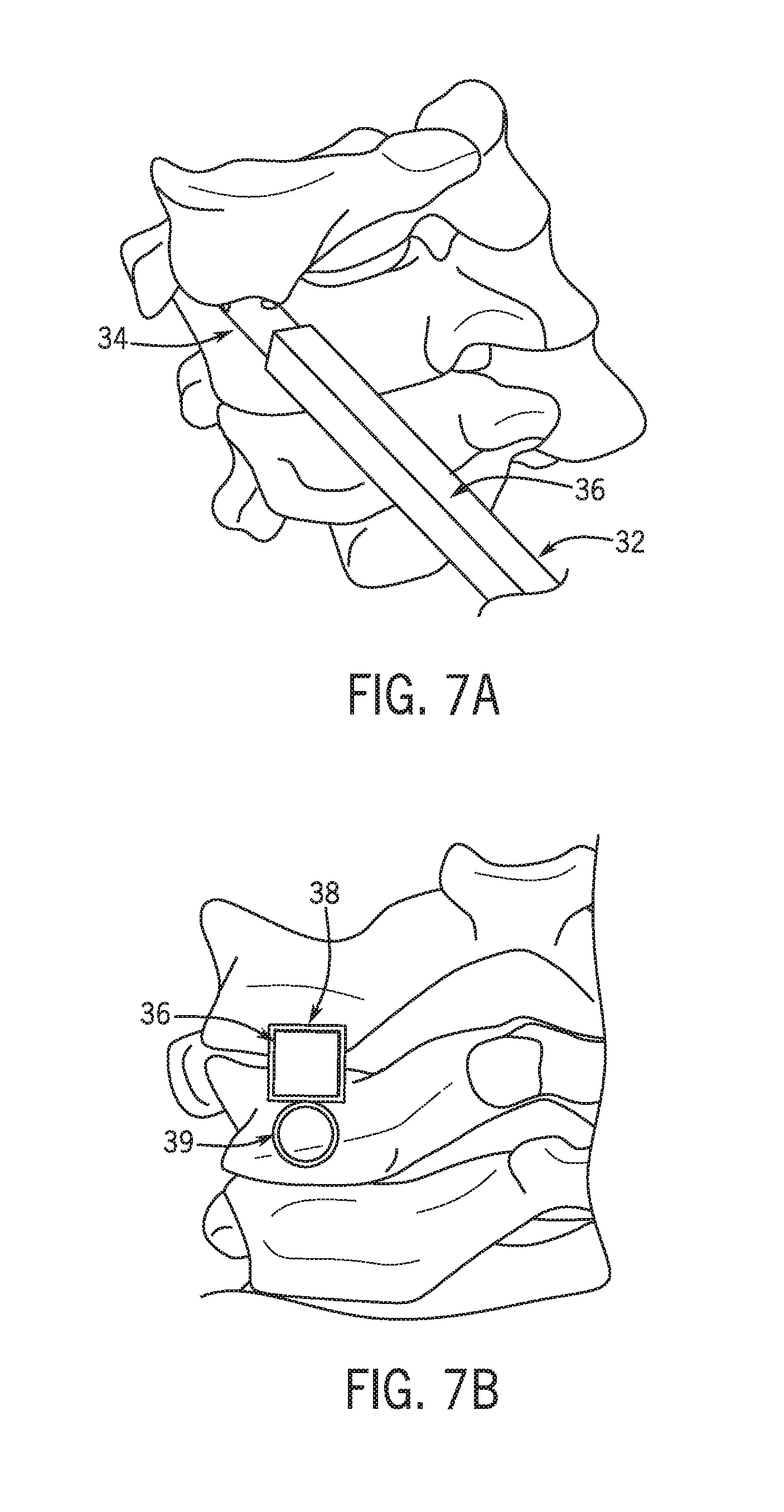
FIGS. 7A and 7B are perspective views of a portion of a cervical spine, illustrating a system and method for inserting a lateral mass implant, according to an embodiment.
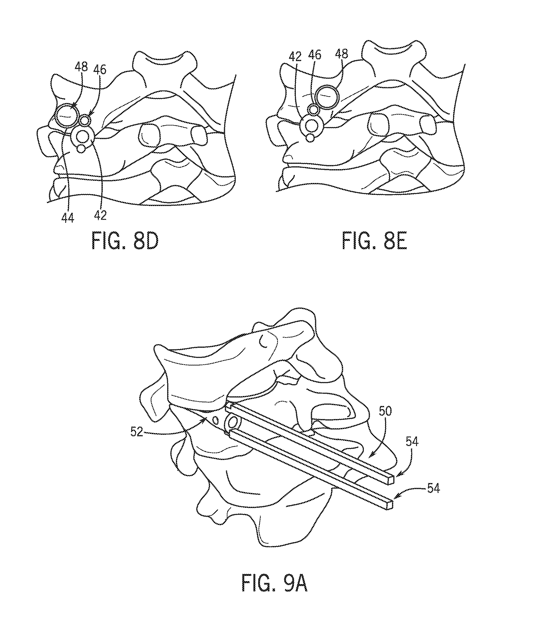
FIGS. 8A-8E are various views of a portion of a cervical spine, illustrating a system and method for inserting a lateral mass implant, according to an embodiment.
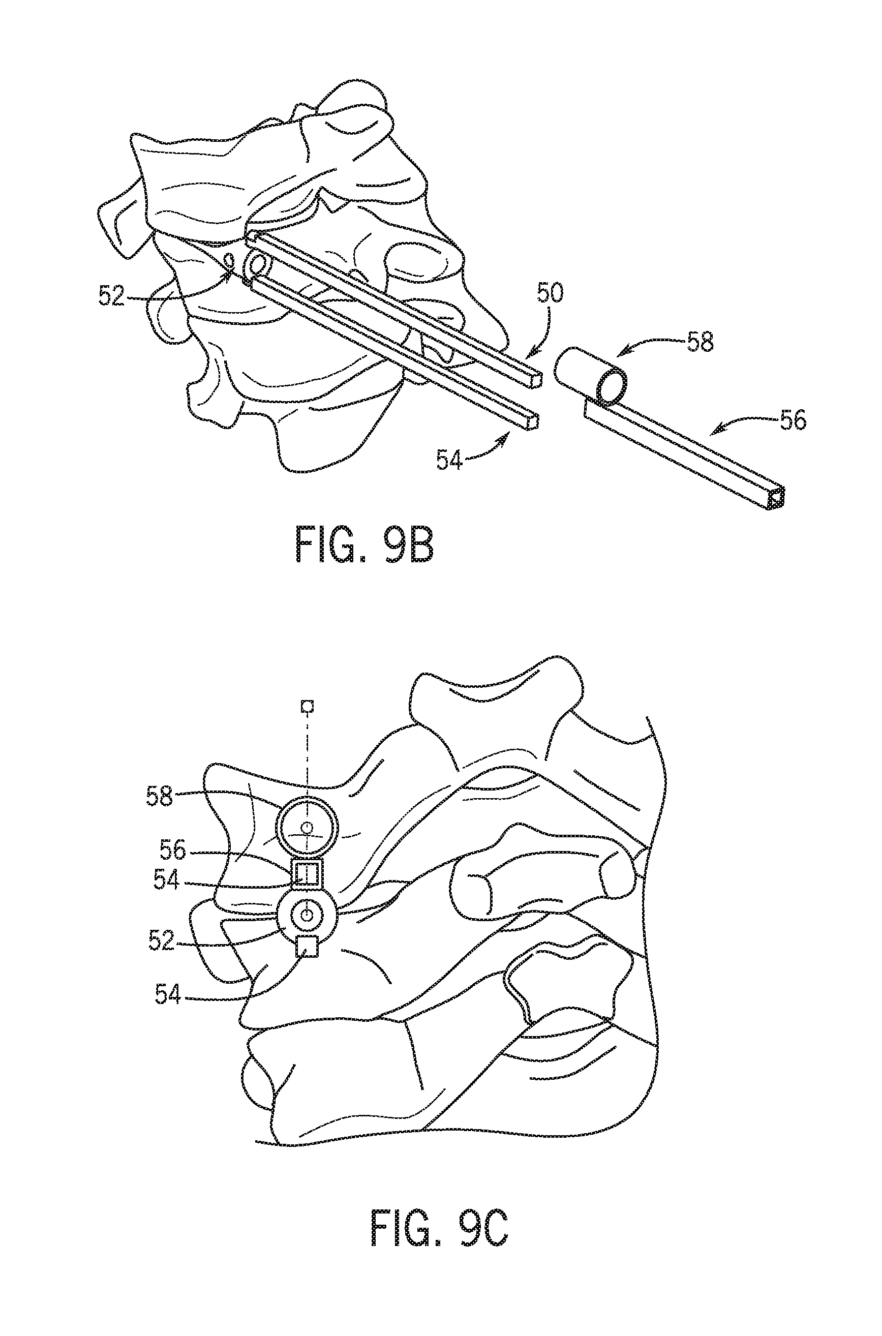
FIGS. 9A-9C are various views of a portion of a cervical spine, illustrating a system and method for inserting a lateral mass implant, according to an embodiment.
FIGS. 10A and 10B are perspective views of a portion of a cervical spine, illustrating a system and method for advancing a decorticator device over a guide device, according to one embodiment.
FIGS. 11A-11D are perspective views of a portion of a cervical spine, illustrating a system and method for advancing a drill through a guide device, according to one embodiment.
FIG. 12 is a perspective view of a portion of a cervical spine, illustrating a system and method for inserting a lateral mass implant, according to an embodiment.
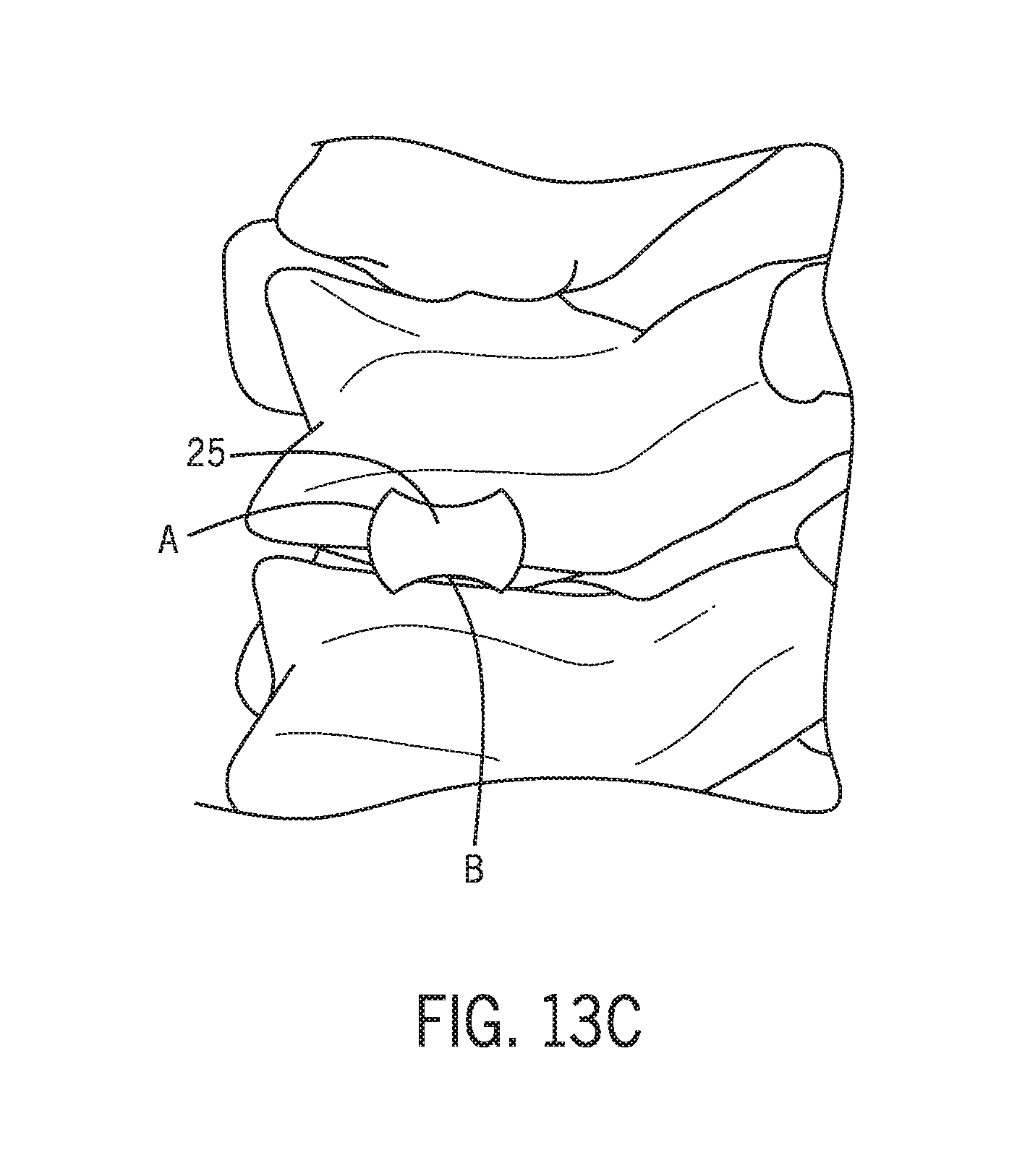
FIGS. 13A-13N illustrate various views of a portion of a cervical spine, illustrating a system and method for inserting a lateral mass implant, according to an embodiment.
DETAILED DESCRIPTION
The various embodiments described herein provide devices, systems and methods for accessing the cervical spine via a posterior approach and implanting a spinal fixation device in the cervical spine. The embodiments allow for a posterior approach using minimally invasive or less invasive techniques. The embodiments described below generally include a guide tool, through which or along which one or more spinal fixation devices may be advanced.
The surgeon may advance the guide tool into the facet from outside the patient though a minimally invasive or less invasive incision, and then may hold the guide tool via a handle or proximal end residing outside the patient. This fixed point deep in the spine can be used to advance drills, awls, plates, rods and screws, to instrument the posterior cervical spine other than the facet, from a percutaneous approach without direct visualization. This avoids stripping all the soft tissue off the spine. A fixed point deep in the patient's spine prevents instruments from slipping off the spine or drills catching soft tissue and skidding out of control. Also, the cervical facet has a fixed anatomic relationship to lateral mass bone consistent in all patients. Instruments can be advanced over the facet tool to reliable landmarks on the lateral mass without direct visualization.
Some of the devices, systems and methods described herein may include, be performed using, or be similar to one or more components of the DTRAX.RTM. Spinal System, from Providence Medical Technology, Inc. (www.providencemt.com). Various components of the DTRAX.RTM. Spinal System may be modified or adjusted, according to various embodiments, for uses described herein.
Referring now to FIGS. 3A and 3B, in one embodiment, a facet guide tool or device 10 may include a distal portion 12 configured for insertion into a facet space between two cervical vertebrae and a proximal portion 14 (or "shaft") that extends proximally from the distal portion 12. The proximal shaft portion 14 is generally long enough to extend from the distal portion 12 to a location outside the patient, where it can be held and manipulated by the surgeon. In one embodiment, the distal portion 12 may include two tines 13. In various embodiments, the distal portion 12 and the proximal portion 14 may either be two attached pieces or may be one piece (e.g. monolithically formed or integrally formed). In some embodiments, the two attached pieces may be detachable, as will be described further below. In some embodiments, the distal portion 12 may be temporary and may be removed once lateral mass fixation is achieved. The distal portion 12 is generally sized and shaped to fit snugly into the facet and abut the pedicle. The tight fit of distal portion 12 in the facet, due to forces applied by ligaments surrounding the area, helps provide stability to the facet guide tool 10 while fixation devices are advanced to the site.
In the embodiment of FIGS. 3A and 3B, the distal portion 12 and proximal portion 14 are hollow, thus forming a central lumen or bore (not visible in the figures), through which one or more facet fixation devices may be advanced. Alternatively or additionally, one or more fixation devices may be advanced over the guide tool 10 to the cervical spine. For example, a fixation device may have a hole formed therethrough of complementary size and shape to the guide tool 10. The hole may be aligned with the guide tool 10 and the fixation device may be advanced along the guide tool.
With reference to FIGS. 4A and 4B, in another embodiment, a facet guide tool or device 20 may include a distal portion 22 and a proximal portion 24. The distal portion 22 may include a beveled edge 23 to aid insertion of the distal portion into a facet. The distal portion 22 and the proximal portion 24 may both be solid, rather than hollow. In this embodiment, the guide tool 20 acts as a rail, over which one or more fixation devices or other devices may be advanced. In use, the guide tool 20 may be inserted in one facet or in multiple facets during a procedure. If used in multiple facets, multiple guide tools 20 may be inserted simultaneously, or the same guide tool may be inserted sequentially into multiple facets, to implant lateral mass or pedicle screw spinal instrumentation from a percutaneous approach. According to various alternative embodiments, the proximal shaft portion 24 may be flexible or rigid. Its purpose is to extend to the skin surface and serve as a guide for drills, plates, rods, screws and/or other tools of spinal instrumentation.
Referring now to FIGS. 5A and 5B, in some embodiments, the distal portion 22 of the guide tool or device 20 may be removable from the proximal portion 24, so that the distal portion 22 may be left in the facet as an implant. In some embodiments, one or more lateral mass fixation devices may then be attached to the distal portion 22 for contacting and attaching to lateral masses of adjacent vertebrae.
With reference to FIGS. 6A-6D, in one embodiment, a system for accessing and attaching fixation devices to a cervical spine facet may include the guide tool or device 20 with distal portion 22 and proximal portion 24, as described above. The system may also include an outer, sliding guide tube 26 and a side-mounted guide member 28 attached to the guide tube 26. A screw 30 may be advanced through the side-mounted guide member 28 for attachment to bone. As illustrated in FIGS. 6C and 6D, sliding guide tube 26 may be rotated about the proximal portion 24 of the guide device 20, to change the position of the side-mounted guide member 28. This change of position may be used, for example, to attach two screws to two adjacent vertebrae. The proximal portion 24 may have different cross-sectional shapes in different embodiments, with the circular cross-sectional shape providing 360-degree rotation of instruments advanced over it.
Referring to FIGS. 7A and 7B, in an alternative embodiment, a facet guide tool or device 32 may include a distal portion 34 and a proximal shaft portion 36 having a square cross-sectional shape. As illustrated in FIG. 7B, an additional guide device 38 may be advanced over the proximal portion 36 and may include a side-mounted guide tube 39. In this embodiment, the square cross-sectional shape of the proximal portion 36 allows instruments to be advanced at a fixed 90 degree angle to the facet surface. This may be useful for lateral mass fixation, because the typical screw fixation is at the midpoint of the lateral mass, which is immediately above the midpoint of the facet.
In yet another embodiment, and with reference now to FIGS. 8A-8E, a facet guide tool 40 may include a distal portion 42 and two or more proximal shafts 44. A guide system may further include a slidable guide instrument 46, with a side-mounted guide 48, which may be used to advance a screw 49 into bone. The proximal shafts 44 may be advantageous, for example, in advancing multiple guide instruments 46 to the cervical spine, either simultaneously or sequentially, for attaching screws to adjacent vertebrae. As illustrated in FIGS. 8D and 8E, the guide instrument 46 may also be rotated over one of the proximal shafts 44 to change the position of the side-mounted guide 48 relative to bone.
FIGS. 9A-9C illustrate yet another embodiment of a facet guide tool or device 50. Similar to the previously described embodiment, in this embodiment, the guide tool 50 includes a distal portion 52 and two or more proximal shafts 54. A guide system may further include a slidable guide instrument 56, with a side-mounted guide 58, which may be used to advance a screw (not shown) into bone. In this embodiment, the proximal shafts 54 have a square cross-sectional shape. As described above, the square cross-sectional shape may be used to orient the guide instrument 56 at 90-degree increments.
FIGS. 10A and 10B illustrate another instrument that may be advanced over a facet guide tool or device 20. In this embodiment, a slidable guide tube 60 with a side-mounted decortication device 62 is shown advancing over the guide tool 20. The decortication tool 62 may be used to cut or decorticate vertebral bone, as part of a fixation procedure. Various embodiments may include this and/or any other similar instrumentation, such as but not limited to screws, staples, posts in the lateral masses, and/or the like. Additional instrumentation, such as a rod or plate, may also be advanced over the facet guide tool 20. Plates generally act as tension bands to connect the rostral and caudal facet and serves to limit flexion and extension as well as lateral bending.
Referring now to FIGS. 11A-11D, in another embodiment, the facet guide tool or device 20 may be used to advance a double-barreled or dual-lumen guide tube device 70, having a side-mounted tube 72, to the cervical spine. As illustrated in FIGS. 11C and 11D, in one embodiment, a drill 74 may be advanced through the side-mounted tube. This guide tube device 70 thus allows for drilling of the lateral mass at the same angle as the facet.
In yet another embodiment, and with reference to FIG. 12, a facet guide tool 80 may have a distal portion 82 and a proximal shaft portion 84, including a slot 86. The slot 86 may be used for advancing a fixation device, such as rod 88 (or plate) and screws 89 for attachment to the rostral and caudal lateral mass.
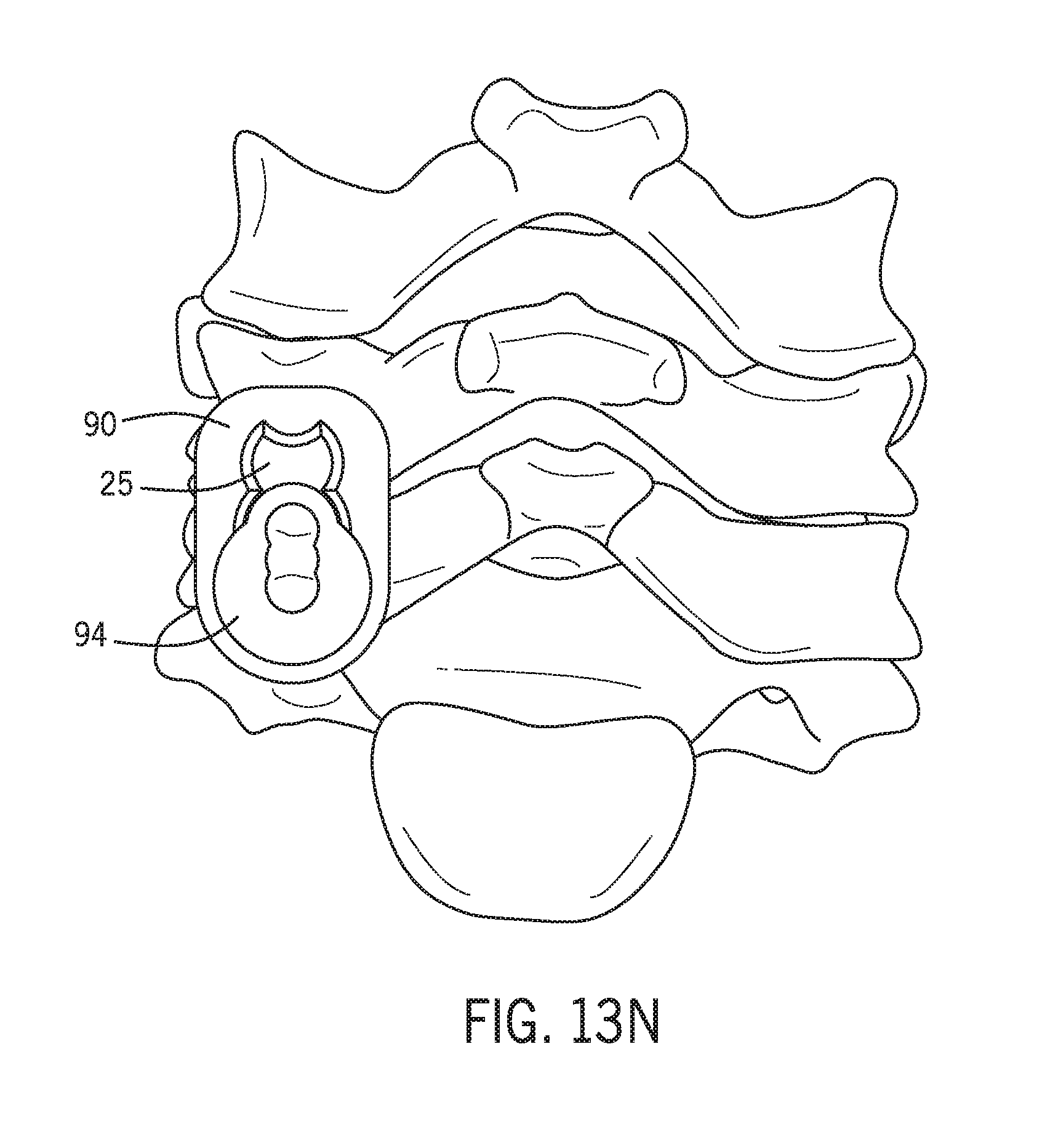
With reference to FIGS. 13A-13N, in one embodiment, a system for accessing and attaching fixation devices to a cervical spine facet 15 may include the guide tool 20 with distal portion 22 and proximal portion 24, as described above (see FIGS. 13A-13B). FIG. 13C illustrates a proximal end 25 of the tool 20 having opposing sides with a concave shape (A) and a convex shape (B). This shaped proximal end helps to maximize accessible lateral mass area and to lock the rotational position of a sliding guide tube 90 shown in later figures. As indicated in FIG. 13D and others, the system may also include an outer, sliding guide tube 90 defining a dual-lumen 92 for receiving both a drill guide 94 and stylet 96 and the guide tool 20.
In use, and as shown in FIGS. 13D-13F, the sliding guide tube 90 may be positioned over and slid onto the proximal portion 24 of the guide device 20, and docked or otherwise stabilized on or at the superior lateral mass 100. The stylet 96 may be removed from the drill guide 94 (FIG. 13G). FIG. 13H depicts an end view of the guide tool 20 and the drill guide 94 within the dual lumen 92 of the sliding guide tube 90. As discussed above, the shape of the tool 20 limits rotational movement of the guide tube 90. As illustrated in FIG. 13I, the drill guide 94 provides one or more guide paths 102 through which a drill, such as drill 74 in FIG. 11C, may be advanced through the guide 94. This guide tube device 90 thus allows for drilling of the lateral mass at or about the same angle as the facet. After drilling the pilot hole for a lateral mass screw, the drill guide 94 is removed from the guide tube 90 (FIG. 13J). As shown in FIG. 13K, a first lumen 104 of the dual lumen tube 90 now provides an opening through which a lateral mass screw (not shown) may be guided for insertion in the pre-drilled location. In some embodiments, a secondary guide tube could be used in the lumen 104 to more precisely guiding the screw to the pre-drilled location.
FIGS. 13L-13N illustrate the guide tool 20, sliding guide tube 90 and the drill guide 94 inserted in an opposite or rotated orientation (e.g. rotated 180.degree. about the longitudinal axis of the guide tool 20) for use and screw insertion in the inferior lateral mass 106.
The C7 and T1 and T2 facets have a fixed relationship to the pedicle. All of the above devices, systems and methods may be used to cannulate the pedicle percutaneously, similar to that described for the lateral mass.
All relative and directional references (including: upper, lower, upward, downward, left, right, leftward, rightward, top, bottom, side, above, below, front, middle, back, vertical, horizontal, and so forth) are given by way of example to aid the reader's understanding of the particular embodiments described herein. They should not be read to be requirements or limitations, particularly as to the position, orientation, or use unless specifically set forth in the claims. Connection references (e.g., attached, coupled, connected, joined, and the like) are to be construed broadly and may include intermediate members between a connection of elements and relative movement between elements. As such, connection references do not necessarily infer that two elements are directly connected and in fixed relation to each other, unless specifically set forth in the claims.
Although the invention has been disclosed in the context of certain embodiments and examples, the present invention extends beyond the specifically disclosed embodiments to other alternative embodiments and/or uses of the invention and obvious modifications and equivalents thereof. Thus, it is intended that the scope of the present invention herein disclosed should not be limited by the particular disclosed embodiments described above.
* * * * *
D00000
D00001
D00002
D00003
D00004
D00005
D00006
D00007
D00008
D00009
D00010
D00011
D00012

D00013
D00014

D00015

D00016

D00017

D00018

D00019

D00020

D00021

D00022
XML
uspto.report is an independent third-party trademark research tool that is not affiliated, endorsed, or sponsored by the United States Patent and Trademark Office (USPTO) or any other governmental organization. The information provided by uspto.report is based on publicly available data at the time of writing and is intended for informational purposes only.
While we strive to provide accurate and up-to-date information, we do not guarantee the accuracy, completeness, reliability, or suitability of the information displayed on this site. The use of this site is at your own risk. Any reliance you place on such information is therefore strictly at your own risk.
All official trademark data, including owner information, should be verified by visiting the official USPTO website at www.uspto.gov. This site is not intended to replace professional legal advice and should not be used as a substitute for consulting with a legal professional who is knowledgeable about trademark law.