Hand strap
Chang , et al. Feb
U.S. patent number 10,201,221 [Application Number 15/790,396] was granted by the patent office on 2019-02-12 for hand strap. This patent grant is currently assigned to GETAC TECHNOLOGY CORPORATION. The grantee listed for this patent is Getac Technology Corporation. Invention is credited to Chia-Wei Chang, Shi-Liang Zhong.


| United States Patent | 10,201,221 |
| Chang , et al. | February 12, 2019 |
Hand strap
Abstract
A hand strap for a portable electronic device is disclosed, wherein the hand strap comprises a fastened portion, a supporting portion and a holding portion. The fastened portion is fixed on a rear surface of the portable electronic device. The supporting portion has a first support body and a second support body. The second support body is rotatable to pivot on the fastened portion in accordance with an axis which is perpendicular to the rear surface of the portable electronic device. In a folded state, the first support body and the second support body are attached to each other. In an extended state, the first support body is inclined an angle corresponding to the second support body so as to support the portable electronic device.
| Inventors: | Chang; Chia-Wei (Taipei, TW), Zhong; Shi-Liang (Taipei, TW) | ||||||||||
|---|---|---|---|---|---|---|---|---|---|---|---|
| Applicant: |
|
||||||||||
| Assignee: | GETAC TECHNOLOGY CORPORATION
(Hsinchu County, TW) |
||||||||||
| Family ID: | 65242340 | ||||||||||
| Appl. No.: | 15/790,396 | ||||||||||
| Filed: | October 23, 2017 |
| Current U.S. Class: | 1/1 |
| Current CPC Class: | A45F 5/10 (20130101); A45F 2200/0516 (20130101); A45F 2005/1006 (20130101); A45F 2200/0525 (20130101); A45C 2200/15 (20130101) |
| Current International Class: | A45F 4/02 (20060101); A45F 5/10 (20060101) |
| Field of Search: | ;224/577,578 |
References Cited [Referenced By]
U.S. Patent Documents
| 5412545 | May 1995 | Rising |
| 6360928 | March 2002 | Russo |
| 7296752 | November 2007 | Carnevali |
| 8604931 | December 2013 | Veloso |
| 8616423 | December 2013 | Wizikowski |
| 8690210 | April 2014 | May |
| 8960634 | February 2015 | Le Gette |
| 9074725 | July 2015 | Trotsky |
| 2004/0233631 | November 2004 | Lord |
| 2008/0156836 | July 2008 | Wadsworth |
| 2009/0219677 | September 2009 | Mori |
| 2009/0321483 | December 2009 | Froloff |
| 2011/0267748 | November 2011 | Lane |
| 2011/0278885 | November 2011 | Procter |
| 2011/0279959 | November 2011 | Lopez |
| 2011/0299231 | December 2011 | Gaddis, II |
| 2012/0104185 | May 2012 | Carroll |
| 2012/0113572 | May 2012 | Gaddis, II |
| 2013/0134267 | May 2013 | Liu |
| 2013/0293072 | November 2013 | Sturniolo |
| 2013/0295549 | November 2013 | Hills |
| 2014/0187297 | July 2014 | Chang |
| 2014/0361057 | December 2014 | Gardner |
| 2015/0041244 | February 2015 | Kam |
| 2015/0173497 | June 2015 | Yu |
| 2015/0175309 | June 2015 | McGowan |
| 2015/0318885 | November 2015 | Earle |
| 2016/0028428 | January 2016 | Sturniolo |
| 102202478 | Sep 2011 | CN | |||
| 201228522 | Jul 2012 | TW | |||
| 201721336 | Jun 2017 | TW | |||
Other References
|
Taiwan Intellectual Property Office, Office Action, dated Aug. 23, 2018, Taiwan. cited by applicant. |
Primary Examiner: Nash; Brian D
Attorney, Agent or Firm: Locke Lord LLP Xia, Esq.; Tim Tingkang
Claims
What is claimed is:
1. A hand strap for use with a portable electronic device, the hand strap comprising: a fastening portion fastened to a rear surface of the portable electronic device; a supporting portion having a first supporting element and a second supporting element, wherein the second supporting element is rotatably pivotally connected to the fastening portion about an axis perpendicular to the rear surface, and an end of the first supporting element is connected to an end of the second supporting element; and a gripping portion disposed on the first supporting element, wherein the first supporting element and the second supporting element overlap and contact each other in a folded state such that the first supporting element covers the second supporting element, and the first supporting element tilts relative to the second supporting element by an angle in an unfolded state, thereby allowing the supporting portion to support the portable electronic device.
2. The hand strap of claim 1, wherein the supporting portion further has a positioning element connected between the first supporting element and the second supporting element, retractable between the first supporting element and the second supporting element in the folded state, and extended between the first supporting element and the second supporting element in the unfolded state, thereby allowing the first supporting element to tilt relative to the second supporting element by the angle.
3. The hand strap of claim 2, wherein the first supporting element has a first engaging structure, and the second supporting element has a second engaging structure, coupling the first engaging structure and the second engaging structure together in the folded state, and separating the second engaging structure and the first engaging structure in the unfolded state.
4. The hand strap of claim 3, wherein the fastening portion has a central connecting element and connecting cords, with the connecting cords each extended from the central connecting element and fastened to the rear surface of the portable electronic device, and the second supporting element being pivotally connected to the central connecting element.
5. The hand strap of claim 4, wherein the gripping portion has an elastic adjustable band and a ring so that, after penetrating the ring, the elastic adjustable band is divided into a first portion and a second portion adjoining the first portion, with the ring being capable of adjusting lengths of the first portion and the second portion, respectively, thereby allowing the first portion and the first supporting element to jointly define a hand receiving space.
6. The hand strap of claim 5, wherein the central connecting element, the first supporting element, and the second supporting element are each a plate, and thus in the folded state the central connecting element, the first supporting element, the second supporting element, and the rear surface are parallel.
7. The hand strap of claim 6, further comprising a pen case disposed beside the first supporting element.
8. The hand strap of claim 3, wherein the first engaging structure and the second engaging structure are each a fastener whereby in the folded state the first engaging structure and the second engaging structure are fastened to each other.
9. The hand strap of claim 3, wherein the first engaging structure is formed at another end of the first supporting element, whereas the second engaging structure extends from another end of the second supporting element to cover the another end of the first supporting element and thereby engage with the first engaging structure in the folded state and is positioned below the positioning element in the unfolded state.
10. The hand strap of claim 4, wherein the connecting cords are extended from two ends of the central connecting element and fastened to the portable electronic device.
11. The hand strap of claim 4, wherein the connecting cords are extended from four corners of the central connecting element and fastened to the portable electronic device.
12. A hand strap for use with a portable electronic device, the hand strap comprising: a fastening portion fastened to a rear surface of the portable electronic device; a supporting portion having a first supporting element and a second supporting element, wherein the second supporting element is rotatably pivotally connected to the fastening portion about an axis perpendicular to the rear surface, and an end of the first supporting element is connected to an end of the second supporting element, wherein the first supporting element and the second supporting element are integrally formed; and a gripping portion disposed on the first supporting element, wherein the first supporting element and the second supporting element overlap in a folded state, and the first supporting element tilts relative to the second supporting element by an angle in an unfolded state, thereby allowing the supporting portion to support the portable electronic device.
Description
BACKGROUND OF THE INVENTION
Field of the Invention
The present invention relates to hand straps and, more particularly, to a hand strap which serves a supporting purpose and is applicable to a portable electronic device.
Description of the Prior Art
With proliferation of portable electronic devices, such as cellular phones and tablets, it is necessary for various conventional hand straps and conventional supports to be developed in order to meet user needs. For instance, a conventional hand strap is disposed on the rear surface of a portable electronic device, and thus a user can hold the portable electronic device easily by gripping the hand strap. In another scenario, a portable electronic device is erected when supported by a conventional support, and thus a user can put the portable electronic device on a desk or any working surface in order to operate the portable electronic device conveniently.
As the functionality of the aforesaid conventional hand strap and conventional support is restricted to gripping and supporting a portable electronic device, respectively, users must not only own both of them but also alternate between them as needed. As a result, the laborious swaps never stop but require space for keeping the one not in use.
In view of the aforesaid drawbacks of the prior art, it is necessary to provide a hand strap with an additional supportive function.
SUMMARY OF THE INVENTION
The present invention provides a hand strap for use with a portable electronic device. The hand strap is disposed on a rear surface of the portable electronic device. In a folded state, a user directly grips the hand strap and rotates the portable electronic device relative to the hand strap by an angle at which the portable electronic device can be operated most conveniently. After the hand strap has been unfolded, the hand strap, now in an unfolded state, supports the portable electronic device so that the portable electronic device is upright and stands on any desktop or working surface.
The hand strap of the present invention is for use with a portable electronic device. The hand strap comprises a fastening portion, a supporting portion and a gripping portion. The fastening portion is fastened to a rear surface of the portable electronic device. The supporting portion has a first supporting element and a second supporting element. The second supporting element is rotatably pivotally connected to the fastening portion about an axis perpendicular to the rear surface. An end of the first supporting element is connected to an end of the second supporting element. The gripping portion is disposed on the first supporting element. The first supporting element and the second supporting element overlap in a folded state, and the first supporting element tilts relative to the second supporting element by an angle in an unfolded state, thereby allowing the supporting portion to support the portable electronic device.
The supporting portion further has a positioning element connected between the first supporting element and the second supporting element. The positioning element is retractedly positioned between the first supporting element and the second supporting element in the folded state and extendedly connected between the first supporting element and the second supporting element in the unfolded state, thereby allowing the first supporting element to tilt relative to the second supporting element by the angle.
The first supporting element has a first engaging structure, and the second supporting element has a second engaging structure. In the folded state, the first engaging structure and the second engaging structure are coupled together. In the unfolded state, the second engaging structure and the first engaging structure separate.
The fastening portion has a central connecting element and connecting cords. The connecting cords are each extended from the central connecting element and fastened to the rear surface of the portable electronic device. The second supporting element is pivotally connected to the central connecting element.
The gripping portion has an elastic adjustable band and a ring. After penetrating the ring, the elastic adjustable band is divided into a first portion and a second portion. The first portion and the second portion adjoin each other. The ring adjusts the lengths of the first portion and the second portion. The first portion and the first supporting element jointly define a hand receiving space.
The central connecting element, the first supporting element, and the second supporting element are each a plate. In the folded state, the central connecting element, the first supporting element, the second supporting element, and the rear surface are parallel.
In an embodiment of the present invention, the hand strap further comprises a pen case disposed beside the first supporting element.
In an embodiment of the present invention, the first engaging structure and the second engaging structure are each a fastener whereby in the folded state the first engaging structure and the second engaging structure are fastened to each other. The connecting cords are extended from two ends of the central connecting element and fastened to the portable electronic device.
In another embodiment of the present invention, the first engaging structure is disposed at another end of the first supporting element, whereas the second engaging structure extends from another end of the second supporting element. In the folded state, the second engaging structure covers the another end of the first supporting element to engage with the first engaging structure. In the unfolded state, the second engaging structure is disposed below the positioning element. The connecting cords are extended from four corners of the central connecting element and fastened to the portable electronic device.
The aforesaid objectives, technical features, and advantages of the present invention are hereunder illustrated with preferred embodiments in conjunction with the accompanying drawings.
BRIEF DESCRIPTION OF THE DRAWINGS
FIG. 1 is a perspective view of a hand strap according to the first embodiment of the present invention;
FIG. 2 is a perspective view of the hand strap mounted on a portable electronic device according to the first embodiment of the present invention;
FIG. 3 is another perspective view of the hand strap mounted on the portable electronic device according to the first embodiment of the present invention;
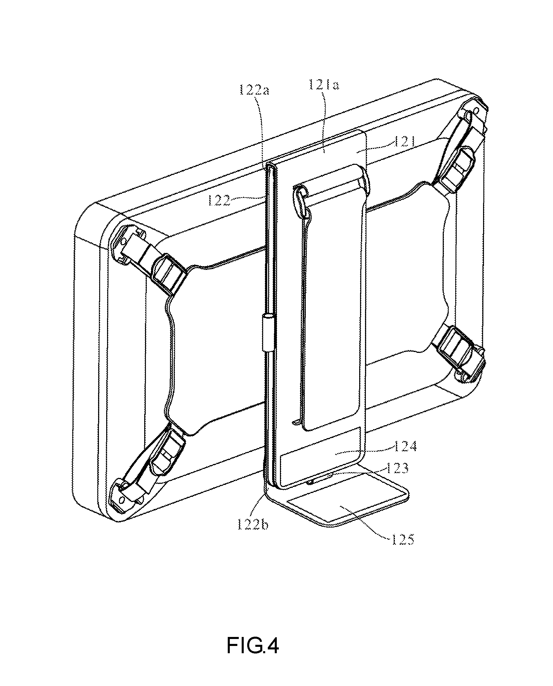
FIG. 4 is a perspective view of the hand strap before an unfolded state thereof according to the first embodiment of the present invention;
FIG. 5 is a perspective view of the hand strap in the unfolded state thereof according to the first embodiment of the present invention;
FIG. 6 is a perspective view of the hand strap coupled to the portable electronic device according to the second embodiment of the present invention; and
FIG. 7 is a perspective view of the hand strap in the unfolded state thereof according to the second embodiment of the present invention.
DETAILED DESCRIPTION OF THE EMBODIMENTS
Referring to FIG. 1 and FIG. 2, there are shown a perspective view of a hand strap 1 according to the first embodiment of the present invention and a perspective view of the hand strap 1 mounted on a portable electronic device E according to the first embodiment of the present invention, respectively. In this embodiment, the hand strap 1 is for use with the portable electronic device E, such as a tablet or a cellular phone, and comprises a fastening portion 11, a supporting portion 12, and a gripping portion 13. The fastening portion 11 is disposed on a rear surface E1 of the portable electronic device E, whereas the supporting portion 12 is disposed on the fastening portion 11, thereby allowing the hand strap 1 to be selectively unfolded and thus adapted to support the portable electronic device E. With the gripping portion 13 being disposed on the supporting portion 12, the user can manually grip the gripping portion 13 and hold the portable electronic device E in operation. Components of the hand strap 1 are hereunder described in terms of their structural features and relationship.
The fastening portion 11 has a central connecting element 111 and connecting cords 112. The connecting cords 112 are each extended from the central connecting element 111 (as shown in FIG. 2) and fastened to the rear surface E1 of the portable electronic device E; hence, the hand strap 1 can be disposed on the portable electronic device E.
The supporting portion 12 has a first supporting element 121, a second supporting element 122, a positioning element 123, a first engaging structure 124 and a second engaging structure 125. In this embodiment, for the sake of illustration of how the supporting portion 12 rotates, an axis A is defined as being perpendicular to the rear surface E1 of the portable electronic device E. The second supporting element 122 is rotatably pivotally connected to the central connecting element 111 about the axis A. An end 121a of the first supporting element 121 is connected to one end 122a of the second supporting element 122, whereas the positioning element 123 is connected between the first supporting element 121 and the second supporting element 122, as shown in FIG. 5. In this embodiment, the first engaging structure 124 is formed on the first supporting element 121, and the second engaging structure 125 extends from the other end 122b of the second supporting element 122.
Referring to FIG. 1, in a folded state, the second engaging structure 125 covers the first engaging structure 124 to not only allow the first supporting element 121 and the second supporting element 122 to overlap exactly, but also allow the positioning element 123 to be retractedly positioned between the first supporting element 121 and the second supporting element 122, as shown in FIG. 4. In this embodiment, the central connecting element 111, the first supporting element 121, and the second supporting element 122 are each a plate, and thus in the folded state the central connecting element 111, the first supporting element 121, the second supporting element 122, and the rear surface E1 are substantially parallel.
Referring to FIG. 2 and FIG. 3, there is shown in FIG. 3 another perspective view of the hand strap according to the first embodiment of the present invention. The gripping portion 13 is disposed on the first supporting element 121 and has an elastic adjustable band 131 and a ring 132. After penetrating the ring 132, the elastic adjustable band 131 is divided into a first portion 131a and a second portion 131b. The first portion 131a and the second portion 131b adjoin each other. The first portion 131a and the first supporting element 121 jointly define a hand receiving space S. The user's hand inserted into the hand receiving space S is covered by the first portion 131a up to an appropriate length thereof in accordance with the width and thickness of the user's hand, as the lengths of the first portion 131a and second portion 131b are adjusted by the ring 132. Therefore, the user can hold the portable electronic device E in operation by hand with the gripping portion 13.
Referring to FIG. 3, after gripping the hand strap 1, the user rotates the portable electronic device E relative to the second supporting element 122 about the axis A while keeping the second supporting element 122, the central connecting element 111 and the rear surface E1 parallel, thereby allowing the first supporting element to attain a tilt angle conducive to operation.
Referring to FIG. 4, prior to an unfolded state, the hand strap 1 will be ready for use, only if the second engaging structure 125 and the first engaging structure 124 separate. Referring to FIG. 5, there is shown a perspective view of the hand strap 1 in the unfolded state thereof according to the first embodiment of the present invention. The first supporting element 121 rotates, with the end 122a serving as a fulcrum, by an angle .theta. to move away from the second supporting element 122. The positioning element 123 is extendedly connected between the first supporting element 121 and the second supporting element 122, and the second engaging structure 125 is disposed below the positioning element 123, thereby allowing the first supporting element 121 to tilt relative to the second supporting element 122 by the angle .theta.. Furthermore, the first supporting element 121 is restrained by the positioning element 123 and thus positioned in place. Hence, the first supporting element 121, the second supporting element 122 and the positioning element 123 jointly form a triangular support whereby the portable electronic device E stands on any desktop or working surface when supported by the supporting portion 12.
In a variant embodiment of the present invention, the length of the positioning element 123 is adjusted according to the size, weight and the like of the portable electronic device E so that the first supporting element 121 tilts relative to the second supporting element 122 by the maximum angle .theta.. In this embodiment, the hand strap 1 further comprises a pen case 14 disposed beside the first supporting element 121 and positioned proximate to the gripping portion 13. If the portable electronic device E comprises a stylus, the user can choose to place the stylus in the pen case 14, allowing the user to take the stylus directly by hand while gripping the gripping portion 13. The first engaging structure 124 and the second engaging structure 125 together form a hook-and-loop fastener in this embodiment, but are coupled together in the other ways in variant embodiments of the present invention.
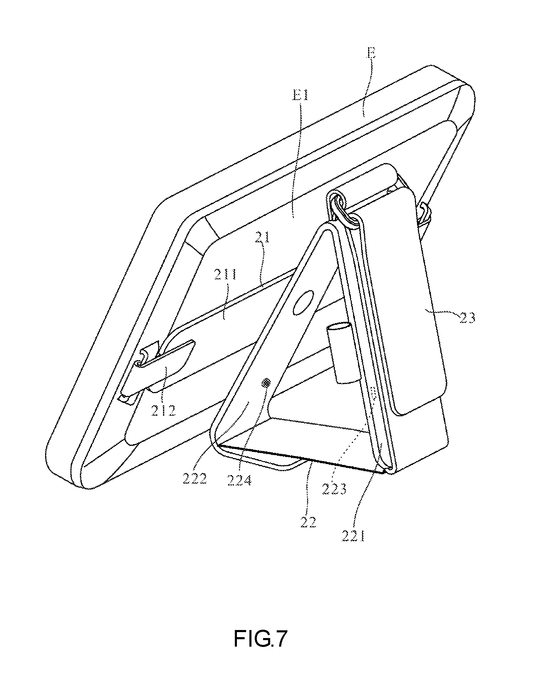
Referring to FIG. 6 and FIG. 7, there are shown a perspective view of a hand strap 2 in the folded state thereof according to the second embodiment of the present invention and a perspective view of the hand strap 2 in the unfolded state thereof according to the second embodiment of the present invention, respectively. In this embodiment, the hand strap 2 comprises a fastening portion 21, a supporting portion 22 and a gripping portion 23. The fastening portion 21 is disposed on the rear surface E1 of the portable electronic device E. In the folded state, the gripping portion 23 is conducive to the user's grip on the portable electronic device E. In the unfolded state, the supporting portion 22 supports the portable electronic device E and thus enables the portable electronic device E to stand. The second embodiment differs from the first embodiment in that in the second embodiment the connecting cords 212 of the fastening portion 21 are extended from two ends of a central connecting element 211 and fastened to the rear surface E1 of the portable electronic device E. In this embodiment, a first engaging structure 223 (indicated by the dashed line of FIG. 7) and a second engaging structure 224 of the supporting portion 22 are two fasteners and form a first supporting element 221 and a second supporting element 222 opposing the first supporting element 221, respectively. In the folded state, the first engaging structure 223 and the second engaging structure 224 are engaged with each other so that the first supporting element 221 and the second supporting element 222 overlap.
In conclusion, after a hand strap of the present invention has been placed on a rear surface of a portable electronic device, the hand strap in a folded state assists a user in holding the portable electronic device by hand firmly and in an unfolded state gives sufficient support to the portable electronic device, thereby allowing the portable electronic device to be placed on any working surface and stand thereon. With the hand strap being capable of serving a gripping purpose and a supporting function simultaneously, not only does the user fold and unfold the hand strap as needed quickly and conveniently, but the quantity of accessories of the portable electronic device is also reduced.
The aforesaid embodiments illustrate the implemented aspects of the present invention and explain the technical features of the present invention rather than restrict the claims of the present invention. All changes and equivalent arrangements readily made to the embodiments of the present invention by persons skilled in the art shall be deemed falling into the scope of the appended claims. Accordingly, the legal protection for the present invention should be defined by the appended claims.
* * * * *
D00000
D00001
D00002
D00003
D00004
D00005
D00006
D00007
XML
uspto.report is an independent third-party trademark research tool that is not affiliated, endorsed, or sponsored by the United States Patent and Trademark Office (USPTO) or any other governmental organization. The information provided by uspto.report is based on publicly available data at the time of writing and is intended for informational purposes only.
While we strive to provide accurate and up-to-date information, we do not guarantee the accuracy, completeness, reliability, or suitability of the information displayed on this site. The use of this site is at your own risk. Any reliance you place on such information is therefore strictly at your own risk.
All official trademark data, including owner information, should be verified by visiting the official USPTO website at www.uspto.gov. This site is not intended to replace professional legal advice and should not be used as a substitute for consulting with a legal professional who is knowledgeable about trademark law.