Continuously variable transmission
Lohr , et al. Fe
U.S. patent number 10,197,147 [Application Number 15/074,267] was granted by the patent office on 2019-02-05 for continuously variable transmission. This patent grant is currently assigned to Fallbrook Intellectual Property Company LLC. The grantee listed for this patent is Fallbrook Intellectual Property Company LLC. Invention is credited to Charles B. Lohr, Brad P. Pohl.


| United States Patent | 10,197,147 |
| Lohr , et al. | February 5, 2019 |
Continuously variable transmission
Abstract
Components, subassemblies, systems, and/or methods for continuously variable transmissions (CVT) are provided. In one embodiment, a CVT has a number of spherical planets in contact with an idler assembly. Various idler assemblies can be used to facilitate to improve durability, fatigue life, and efficiency of a CVT. In one embodiment, the idler assembly has two rolling elements having contact surfaces that are angled with respect to a longitudinal axis of the CVT. In some embodiments, a bearing is operably coupled between the first and second rolling elements. The bearing is configured to balance axial force between the first and second rolling elements. In one embodiment, the bearing is a ball bearing. In another embodiment, the bearing is an angular contact bearing. In yet other embodiments, needle roller bearings are employed.
| Inventors: | Lohr; Charles B. (Austin, TX), Pohl; Brad P. (Leander, TX) | ||||||||||
|---|---|---|---|---|---|---|---|---|---|---|---|
| Applicant: |
|
||||||||||
| Assignee: | Fallbrook Intellectual Property
Company LLC (Cedar Park, TX) |
||||||||||
| Family ID: | 46020177 | ||||||||||
| Appl. No.: | 15/074,267 | ||||||||||
| Filed: | March 18, 2016 |
Prior Publication Data
| Document Identifier | Publication Date | |
|---|---|---|
| US 20160201772 A1 | Jul 14, 2016 | |
Related U.S. Patent Documents
| Application Number | Filing Date | Patent Number | Issue Date | ||
|---|---|---|---|---|---|
| 14541875 | Nov 14, 2014 | 9291251 | |||
| 13288711 | Nov 18, 2014 | 8888643 | |||
| 61412290 | Nov 10, 2010 | ||||
| Current U.S. Class: | 1/1 |
| Current CPC Class: | F16H 57/0484 (20130101); F16C 19/545 (20130101); F16H 57/0487 (20130101); F16H 55/32 (20130101); F16H 15/50 (20130101); F16H 2057/085 (20130101); F16H 15/52 (20130101); F16H 15/503 (20130101); B62M 11/16 (20130101) |
| Current International Class: | F16H 15/50 (20060101); F16C 19/54 (20060101); F16H 15/52 (20060101); F16H 55/32 (20060101); F16H 57/04 (20100101); B62M 11/16 (20060101); F16H 57/08 (20060101) |
References Cited [Referenced By]
U.S. Patent Documents
| 719595 | February 1903 | Huss |
| 1121210 | December 1914 | Techel |
| 1175677 | March 1916 | Barnes |
| 1207985 | December 1916 | Null et al. |
| 1380006 | May 1921 | Nielsen |
| 1390971 | September 1921 | Samain |
| 1558222 | October 1925 | Beetow |
| 1629092 | May 1927 | Arter et al. |
| 1629902 | May 1927 | Arter et al. |
| 1686446 | October 1928 | Gilman |
| 1774254 | August 1930 | Daukus |
| 1793571 | February 1931 | Vaughn |
| 1847027 | February 1932 | Thomsen et al. |
| 1850189 | March 1932 | Weiss |
| 1858696 | May 1932 | Weiss |
| 1865102 | June 1932 | Hayes |
| 1903228 | March 1933 | Thomson |
| 1978439 | October 1934 | Sharpe |
| 2030203 | February 1936 | Gove et al. |
| 2060884 | November 1936 | Madle |
| 2086491 | July 1937 | Dodge |
| 2100629 | November 1937 | Chilton |
| 2109845 | March 1938 | Madle |
| 2112763 | March 1938 | Cloudsley |
| 2131158 | September 1938 | Almen et al. |
| 2134225 | October 1938 | Christiansen |
| 2152796 | April 1939 | Erban |
| 2196064 | April 1940 | Erban |
| 2209254 | July 1940 | Ahnger |
| 2259933 | October 1941 | Holloway |
| 2269434 | January 1942 | Brooks |
| 2325502 | July 1943 | Auguste |
| RE22761 | May 1946 | Wemp |
| 2461258 | February 1949 | Brooks |
| 2469653 | May 1949 | Kopp |
| 2480968 | September 1949 | Ronai |
| 2553465 | May 1951 | Monge |
| 2586725 | February 1952 | Henry |
| 2595367 | May 1952 | Picanol |
| 2596538 | May 1952 | Dicke |
| 2597849 | May 1952 | Alfredeen |
| 2675713 | April 1954 | Acker |
| 2696888 | December 1954 | Chillson et al. |
| 2868038 | May 1955 | Billeter |
| 2716357 | August 1955 | Rennerfelt |
| 2730904 | January 1956 | Rennerfelt |
| 2748614 | June 1956 | Weisel |
| 2959070 | January 1959 | Flinn |
| 2873911 | February 1959 | Perrine |
| 2874592 | February 1959 | Oehrli |
| 2883883 | April 1959 | Chillson |
| 2891213 | June 1959 | Kern |
| 2901924 | September 1959 | Banker |
| 2913932 | November 1959 | Oehrli |
| 2931234 | April 1960 | Hayward |
| 2931235 | April 1960 | Hayward |
| 2949800 | August 1960 | Neuschotz |
| 2959063 | November 1960 | Perry |
| 2959972 | November 1960 | Madson |
| 2964959 | December 1960 | Beck |
| 3008061 | November 1961 | Mims et al. |
| 3035460 | May 1962 | Guichard |
| 3048056 | August 1962 | Wolfram |
| 3051020 | August 1962 | Hartupee |
| 3086704 | April 1963 | Hurtt |
| 3087348 | April 1963 | Kraus |
| 3154957 | November 1964 | Kashihara |
| 3163050 | December 1964 | Kraus |
| 3176542 | April 1965 | Monch |
| 3184983 | May 1965 | Kraus |
| 3204476 | September 1965 | Rouverol |
| 3209606 | October 1965 | Yamamoto |
| 3211364 | October 1965 | Wentling et al. |
| 3216283 | November 1965 | General |
| 3229538 | January 1966 | Schlottler |
| 3237468 | March 1966 | Schlottler |
| 3246531 | April 1966 | Kashihara |
| 3248960 | May 1966 | Schottler |
| 3273468 | September 1966 | Allen |
| 3280646 | October 1966 | Lemieux |
| 3283614 | November 1966 | Hewko |
| 3292443 | December 1966 | Felix |
| 3340895 | September 1967 | Osgood, Jr. et al. |
| 3407687 | October 1968 | Hayashi |
| 3430504 | March 1969 | Dickenbrock |
| 3439563 | April 1969 | Petty |
| 3440895 | April 1969 | Fellows |
| 3464281 | September 1969 | Hiroshi et al. |
| 3477315 | November 1969 | Macks |
| 3487726 | January 1970 | Burnett |
| 3487727 | January 1970 | Gustafsson |
| 3574289 | April 1971 | Scheiter et al. |
| 3581587 | June 1971 | Dickenbrock |
| 3661404 | May 1972 | Bossaer |
| 3695120 | October 1972 | Titt |
| 3707888 | January 1973 | Schottler |
| 3727473 | April 1973 | Bayer |
| 3727474 | April 1973 | Fullerton |
| 3736803 | June 1973 | Horowitz et al. |
| 3768715 | October 1973 | Tout |
| 3800607 | April 1974 | Zurcher |
| 3802284 | April 1974 | Sharpe et al. |
| 3810398 | May 1974 | Kraus |
| 3820416 | June 1974 | Kraus |
| 3866985 | February 1975 | Whitehurst |
| 3891235 | June 1975 | Shelly |
| 3934493 | January 1976 | Hillyer |
| 3954282 | May 1976 | Hege |
| 3987681 | October 1976 | Keithley et al. |
| 3996807 | December 1976 | Adams |
| 4023442 | May 1977 | Woods et al. |
| 4098146 | July 1978 | McLarty |
| 4103514 | August 1978 | Grosse-Entrup |
| 4159653 | July 1979 | Koivunen |
| 4169609 | October 1979 | Zampedro |
| 4177683 | December 1979 | Moses |
| 4227712 | October 1980 | Dick |
| 4314485 | February 1982 | Adams |
| 4345486 | August 1982 | Olesen |
| 4369667 | January 1983 | Kemper |
| 4382186 | May 1983 | Cronin |
| 4391156 | July 1983 | Tibbals |
| 4459873 | July 1984 | Black |
| 4464952 | August 1984 | Stubbs |
| 4468984 | September 1984 | Castelli et al. |
| 4494524 | January 1985 | Wagner |
| 4496051 | January 1985 | Ortner |
| 4501172 | February 1985 | Kraus |
| 4515040 | May 1985 | Takeuchi et al. |
| 4526255 | July 1985 | Hennessey et al. |
| 4546673 | October 1985 | Shigematsu et al. |
| 4560369 | December 1985 | Hattori |
| 4567781 | February 1986 | Russ |
| 4569670 | February 1986 | McIntosh |
| 4574649 | March 1986 | Seol |
| 4585429 | April 1986 | Marier |
| 4617838 | October 1986 | Anderson |
| 4630839 | December 1986 | Seol |
| 4631469 | December 1986 | Tsuboi et al. |
| 4651082 | March 1987 | Kaneyuki |
| 4663990 | May 1987 | Itoh et al. |
| 4700581 | October 1987 | Tibbals, Jr. |
| 4713976 | December 1987 | Wilkes |
| 4717368 | January 1988 | Yamaguchi et al. |
| 4735430 | April 1988 | Tomkinson |
| 4738164 | April 1988 | Kaneyuki |
| 4744261 | May 1988 | Jacobson |
| 4756211 | July 1988 | Fellows |
| 4781663 | November 1988 | Reswick |
| 4838122 | June 1989 | Takamiya et al. |
| 4856374 | August 1989 | Kreuzer |
| 4869130 | September 1989 | Wiecko |
| 4881925 | November 1989 | Hattori |
| 4900046 | February 1990 | Aranceta-Angoitia |
| 4909101 | March 1990 | Terry |
| 4918344 | April 1990 | Chikamori et al. |
| 4964312 | October 1990 | Kraus |
| 5006093 | April 1991 | Itoh et al. |
| 5020384 | June 1991 | Kraus |
| 5025685 | June 1991 | Kobayashi et al. |
| 5033322 | July 1991 | Nakano |
| 5033571 | July 1991 | Morimoto |
| 5037361 | August 1991 | Takahashi |
| 5044214 | September 1991 | Barber |
| 5059158 | October 1991 | Bellio et al. |
| 5069655 | December 1991 | Schivelbusch |
| 5083982 | January 1992 | Sato |
| 5099710 | March 1992 | Nakano |
| 5121654 | June 1992 | Fasce |
| 5125677 | June 1992 | Ogilvie et al. |
| 5138894 | August 1992 | Kraus |
| 5156412 | October 1992 | Meguerditchian |
| 5230258 | July 1993 | Nakano |
| 5236211 | August 1993 | Meguerditchian |
| 5236403 | August 1993 | Schievelbusch |
| 5267920 | December 1993 | Hibi |
| 5273501 | December 1993 | Schievelbusch |
| 5318486 | June 1994 | Lutz |
| 5319486 | June 1994 | Vogel et al. |
| 5330396 | July 1994 | Lohr et al. |
| 5355749 | October 1994 | Obara et al. |
| 5375865 | December 1994 | Terry, Sr. |
| 5379661 | January 1995 | Nakano |
| 5383677 | January 1995 | Thomas |
| 5387000 | February 1995 | Sato |
| 5401221 | March 1995 | Fellows et al. |
| 5451070 | September 1995 | Lindsay et al. |
| 5489003 | February 1996 | Ohyama et al. |
| 5508574 | April 1996 | Vlock |
| 5562564 | October 1996 | Folino |
| 5564998 | October 1996 | Fellows |
| 5601301 | February 1997 | Liu |
| 5607373 | March 1997 | Ochiai et al. |
| 5645507 | July 1997 | Hathaway |
| 5651750 | July 1997 | Imanishi et al. |
| 5664636 | September 1997 | Ikuma et al. |
| 5669845 | September 1997 | Muramoto et al. |
| 5690346 | November 1997 | Keskitalo |
| 5722502 | March 1998 | Kubo |
| 5746676 | May 1998 | Kawase et al. |
| 5755303 | May 1998 | Yamamoto et al. |
| 5799541 | September 1998 | Arbeiter |
| 5823052 | October 1998 | Nobumoto |
| 5846155 | December 1998 | Taniguchi et al. |
| 5888160 | March 1999 | Miyata et al. |
| 5895337 | April 1999 | Fellows et al. |
| 5899827 | May 1999 | Nakano et al. |
| 5902207 | May 1999 | Sugihara |
| 5967933 | October 1999 | Valdenaire |
| 5976054 | November 1999 | Yasuoka |
| 5984826 | November 1999 | Nakano |
| 5995895 | November 1999 | Watt et al. |
| 6000707 | December 1999 | Miller |
| 6003649 | December 1999 | Fischer |
| 6004239 | December 1999 | Makino |
| 6006151 | December 1999 | Graf |
| 6012538 | January 2000 | Sonobe et al. |
| 6015359 | January 2000 | Kunii |
| 6019701 | February 2000 | Mori et al. |
| 6029990 | February 2000 | Busby |
| 6042132 | March 2000 | Suenaga et al. |
| 6045477 | April 2000 | Schmidt |
| 6045481 | April 2000 | Kumagai |
| 6053833 | April 2000 | Masaki |
| 6053841 | April 2000 | Kolde et al. |
| 6054844 | April 2000 | Frank |
| 6066067 | May 2000 | Greenwood |
| 6071210 | June 2000 | Kato |
| 6074320 | June 2000 | Miyata et al. |
| 6076846 | June 2000 | Clardy |
| 6079726 | June 2000 | Busby |
| 6083139 | July 2000 | Deguchi |
| 6086506 | July 2000 | Petersmann et al. |
| 6095940 | August 2000 | Ai et al. |
| 6099431 | August 2000 | Hoge et al. |
| 6101895 | August 2000 | Yamane |
| 6113513 | September 2000 | Itoh et al. |
| 6119539 | September 2000 | Papanicolaou |
| 6119800 | September 2000 | McComber |
| 6159126 | December 2000 | Oshidari |
| 6171210 | January 2001 | Miyata et al. |
| 6174260 | January 2001 | Tsukada et al. |
| 6186922 | February 2001 | Bursal et al. |
| 6210297 | April 2001 | Knight |
| 6217473 | April 2001 | Ueda et al. |
| 6217478 | April 2001 | Vohmann et al. |
| 6241636 | June 2001 | Miller |
| 6243638 | June 2001 | Abo et al. |
| 6251038 | June 2001 | Ishikawa et al. |
| 6258003 | July 2001 | Hirano et al. |
| 6261200 | July 2001 | Miyata et al. |
| 6296593 | October 2001 | Gotou |
| 6311113 | October 2001 | Danz et al. |
| 6312358 | November 2001 | Goi et al. |
| 6322475 | November 2001 | Miller |
| 6325386 | December 2001 | Shoge |
| 6358174 | March 2002 | Folsom et al. |
| 6358178 | March 2002 | Wittkopp |
| 6367833 | April 2002 | Horiuchi |
| 6371878 | April 2002 | Bowen |
| 6375412 | April 2002 | Dial |
| 6390945 | May 2002 | Young |
| 6390946 | May 2002 | Hibi et al. |
| 6406399 | June 2002 | Ai |
| 6414401 | July 2002 | Kuroda et al. |
| 6419608 | July 2002 | Miller |
| 6425838 | July 2002 | Matsubara et al. |
| 6434960 | August 2002 | Rousseau |
| 6440037 | August 2002 | Takagi et al. |
| 6459978 | October 2002 | Tamiguchi et al. |
| 6461268 | October 2002 | Milner |
| 6482094 | November 2002 | Kefes |
| 6492785 | December 2002 | Kasten et al. |
| 6494805 | December 2002 | Ooyama et al. |
| 6499373 | December 2002 | Van Cor |
| 6514175 | February 2003 | Taniguchi et al. |
| 6532890 | March 2003 | Chen |
| 6551210 | April 2003 | Miller |
| 6558285 | May 2003 | Sieber |
| 6575047 | June 2003 | Reik et al. |
| 6659901 | December 2003 | Sakai et al. |
| 6672418 | January 2004 | Makino |
| 6676559 | January 2004 | Miller |
| 6679109 | January 2004 | Gierling et al. |
| 6682432 | January 2004 | Shinozuka |
| 6689012 | February 2004 | Miller |
| 6721637 | April 2004 | Abe et al. |
| 6723014 | April 2004 | Shinso et al. |
| 6723016 | April 2004 | Sumi |
| 6805654 | October 2004 | Nishii |
| 6808053 | October 2004 | Kirkwood et al. |
| 6839617 | January 2005 | Mensler et al. |
| 6849020 | February 2005 | Sumi |
| 6859709 | February 2005 | Joe et al. |
| 6868949 | March 2005 | Braford |
| 6931316 | August 2005 | Joe et al. |
| 6932739 | August 2005 | Miyata et al. |
| 6942593 | September 2005 | Nishii et al. |
| 6945903 | September 2005 | Miller |
| 6949049 | September 2005 | Miller |
| 6958029 | October 2005 | Inoue |
| 6991575 | January 2006 | Inoue |
| 6991579 | January 2006 | Kobayashi et al. |
| 7011600 | March 2006 | Miller et al. |
| 7011601 | March 2006 | Miller |
| 7014591 | March 2006 | Miller |
| 7029418 | April 2006 | Taketsuna et al. |
| 7032914 | April 2006 | Miller |
| 7036620 | May 2006 | Miller et al. |
| 7044884 | May 2006 | Miller |
| 7063195 | June 2006 | Berhan |
| 7063640 | June 2006 | Miller |
| 7074007 | July 2006 | Miller |
| 7074154 | July 2006 | Miller |
| 7074155 | July 2006 | Miller |
| 7077777 | July 2006 | Miyata et al. |
| 7086979 | August 2006 | Frenken |
| 7086981 | August 2006 | Ali et al. |
| 7094171 | August 2006 | Inoue |
| 7111860 | September 2006 | Grimaldos |
| 7112158 | September 2006 | Miller |
| 7112159 | September 2006 | Miller et al. |
| 7125297 | October 2006 | Miller et al. |
| 7131930 | November 2006 | Miller et al. |
| 7140999 | November 2006 | Miller |
| 7147586 | December 2006 | Miller et al. |
| 7153233 | December 2006 | Miller et al. |
| 7156770 | January 2007 | Miller |
| 7160220 | January 2007 | Shinojima et al. |
| 7160222 | January 2007 | Miller |
| 7163485 | January 2007 | Miller |
| 7163486 | January 2007 | Miller et al. |
| 7166052 | January 2007 | Miller et al. |
| 7166056 | January 2007 | Miller et al. |
| 7166057 | January 2007 | Miller et al. |
| 7166058 | January 2007 | Miller et al. |
| 7169076 | January 2007 | Miller et al. |
| 7172529 | February 2007 | Miller et al. |
| 7175564 | February 2007 | Miller |
| 7175565 | February 2007 | Miller et al. |
| 7175566 | February 2007 | Miller et al. |
| 7192381 | March 2007 | Miller et al. |
| 7197915 | April 2007 | Luh et al. |
| 7198582 | April 2007 | Miller et al. |
| 7198583 | April 2007 | Miller et al. |
| 7198584 | April 2007 | Miller et al. |
| 7198585 | April 2007 | Miller et al. |
| 7201693 | April 2007 | Miller et al. |
| 7201694 | April 2007 | Miller et al. |
| 7201695 | April 2007 | Miller et al. |
| 7204777 | April 2007 | Miller et al. |
| 7214159 | May 2007 | Miller et al. |
| 7217215 | May 2007 | Miller et al. |
| 7217216 | May 2007 | Inoue |
| 7217219 | May 2007 | Miller |
| 7217220 | May 2007 | Careau et al. |
| 7226379 | June 2007 | Ibamoto et al. |
| 7232395 | June 2007 | Miller et al. |
| 7234873 | June 2007 | Kato et al. |
| 7235031 | June 2007 | Miller et al. |
| 7238136 | July 2007 | Miller et al. |
| 7238137 | July 2007 | Miller et al. |
| 7238138 | July 2007 | Miller et al. |
| 7238139 | July 2007 | Roethler et al. |
| 7246672 | July 2007 | Shirai et al. |
| 7250018 | July 2007 | Miller et al. |
| 7261663 | August 2007 | Miller et al. |
| 7275610 | October 2007 | Kuang et al. |
| 7285068 | October 2007 | Hosoi |
| 7288042 | October 2007 | Miller et al. |
| 7288043 | October 2007 | Shioiri et al. |
| 7320660 | January 2008 | Miller |
| 7322901 | January 2008 | Miller et al. |
| 7343236 | March 2008 | Wilson |
| 7347801 | March 2008 | Guenter et al. |
| 7383748 | June 2008 | Rankin |
| 7383749 | June 2008 | Rankin |
| 7384370 | June 2008 | Miller |
| 7393300 | July 2008 | Miller et al. |
| 7393302 | July 2008 | Miller |
| 7393303 | July 2008 | Miller |
| 7395731 | July 2008 | Miller et al. |
| 7396209 | July 2008 | Miller et al. |
| 7402122 | July 2008 | Miller |
| 7410443 | August 2008 | Miller |
| 7419451 | September 2008 | Miller |
| 7422541 | September 2008 | Miller |
| 7422546 | September 2008 | Miller et al. |
| 7427253 | September 2008 | Miller |
| 7431677 | October 2008 | Miller et al. |
| 7452297 | November 2008 | Miller et al. |
| 7455611 | November 2008 | Miller et al. |
| 7455617 | November 2008 | Miller et al. |
| 7462123 | December 2008 | Miller et al. |
| 7462127 | December 2008 | Miller et al. |
| 7470210 | December 2008 | Miller et al. |
| 7478885 | January 2009 | Urabe |
| 7481736 | January 2009 | Miller et al. |
| 7510499 | March 2009 | Miller et al. |
| 7540818 | June 2009 | Miller et al. |
| 7547264 | June 2009 | Usoro |
| 7574935 | August 2009 | Rohs et al. |
| 7591755 | September 2009 | Petrzik et al. |
| 7632203 | December 2009 | Miller |
| 7651437 | January 2010 | Miller et al. |
| 7654928 | February 2010 | Miller et al. |
| 7670243 | March 2010 | Miller |
| 7686729 | March 2010 | Miller et al. |
| 7727101 | June 2010 | Miller |
| 7727106 | June 2010 | Maheu et al. |
| 7727107 | June 2010 | Miller |
| 7727108 | June 2010 | Miller et al. |
| 7727110 | June 2010 | Miller et al. |
| 7727115 | June 2010 | Serkh |
| 7731615 | June 2010 | Miller et al. |
| 7762919 | July 2010 | Smithson et al. |
| 7762920 | July 2010 | Smithson et al. |
| 7770674 | August 2010 | Miles et al. |
| 7785228 | August 2010 | Smithson et al. |
| 7828685 | November 2010 | Miller |
| 7837592 | November 2010 | Miller |
| 7871353 | January 2011 | Nichols et al. |
| 7882762 | February 2011 | Armstrong et al. |
| 7883442 | February 2011 | Miller et al. |
| 7885747 | February 2011 | Miller et al. |
| 7887032 | February 2011 | Malone |
| 7909723 | March 2011 | Triller et al. |
| 7909727 | March 2011 | Smithson et al. |
| 7914029 | March 2011 | Miller et al. |
| 7959533 | June 2011 | Nichols et al. |
| 7963880 | June 2011 | Smithson et al. |
| 7967719 | June 2011 | Smithson et al. |
| 7976426 | July 2011 | Smithson et al. |
| 8066613 | November 2011 | Smithson et al. |
| 8066614 | November 2011 | Miller et al. |
| 8070635 | December 2011 | Miller |
| 8087482 | January 2012 | Miles et al. |
| 8123653 | February 2012 | Smithson et al. |
| 8133149 | March 2012 | Smithson et al. |
| 8142323 | March 2012 | Tsuchiya et al. |
| 8167759 | May 2012 | Pohl et al. |
| 8171636 | May 2012 | Smithson et al. |
| 8230961 | July 2012 | Schneidewind |
| 8262536 | September 2012 | Nichols et al. |
| 8267829 | September 2012 | Miller et al. |
| 8313404 | November 2012 | Carter et al. |
| 8313405 | November 2012 | Bazyn et al. |
| 8317650 | November 2012 | Nichols et al. |
| 8317651 | November 2012 | Lohr |
| 8321097 | November 2012 | Vasiliotis et al. |
| 8342999 | January 2013 | Miller |
| 8360917 | January 2013 | Nichols et al. |
| 8376889 | February 2013 | Hoffman et al. |
| 8376903 | February 2013 | Pohl et al. |
| 8382631 | February 2013 | Hoffman et al. |
| 8382637 | February 2013 | Tange |
| 8393989 | March 2013 | Pohl |
| 8398518 | March 2013 | Nichols et al. |
| 8469853 | June 2013 | Miller et al. |
| 8469856 | June 2013 | Thomassy |
| 8480529 | July 2013 | Pohl et al. |
| 8496554 | July 2013 | Pohl et al. |
| 8506452 | August 2013 | Pohl et al. |
| 8512195 | August 2013 | Lohr et al. |
| 8517888 | August 2013 | Brookins |
| 8535199 | September 2013 | Lohr et al. |
| 8550949 | October 2013 | Miller |
| 8585528 | November 2013 | Carter et al. |
| 8608609 | December 2013 | Sherrill |
| 8622866 | January 2014 | Bazyn et al. |
| 8626409 | January 2014 | Vasiliotis et al. |
| 8628443 | January 2014 | Miller et al. |
| 8641572 | February 2014 | Nichols et al. |
| 8641577 | February 2014 | Nichols et al. |
| 8663050 | March 2014 | Nichols et al. |
| 8678974 | March 2014 | Lohr |
| 8708360 | April 2014 | Miller et al. |
| 8721485 | May 2014 | Lohr et al. |
| 8738255 | May 2014 | Carter et al. |
| 8776633 | July 2014 | Armstrong et al. |
| 8784248 | July 2014 | Murakami et al. |
| 8790214 | July 2014 | Lohr et al. |
| 8818661 | August 2014 | Keilers et al. |
| 8827856 | September 2014 | Younggren et al. |
| 8827864 | September 2014 | Durack |
| 8845485 | September 2014 | Smithson et al. |
| 8852050 | October 2014 | Thomassy |
| 8870711 | October 2014 | Pohl et al. |
| 8888643 | November 2014 | Lohr et al. |
| 8900085 | December 2014 | Pohl et al. |
| 8920285 | December 2014 | Smithson et al. |
| 8924111 | December 2014 | Fuller |
| 8961363 | February 2015 | Shiina et al. |
| 8992376 | March 2015 | Ogawa et al. |
| 8996263 | March 2015 | Quinn et al. |
| 9017207 | April 2015 | Pohl et al. |
| 9022889 | May 2015 | Miller |
| 9046158 | June 2015 | Miller et al. |
| 9074674 | July 2015 | Nichols et al. |
| 9086145 | July 2015 | Pohl et al. |
| 9121464 | September 2015 | Nichols et al. |
| 9182018 | November 2015 | Bazyn et al. |
| 9239099 | January 2016 | Carter et al. |
| 9249880 | February 2016 | Vasiliotis et al. |
| 9273760 | March 2016 | Pohl et al. |
| 9279482 | March 2016 | Nichols et al. |
| 9291251 | March 2016 | Lohr |
| 9528561 | December 2016 | Nichols et al. |
| 9574643 | February 2017 | Pohl |
| 9656672 | May 2017 | Schieffelin |
| 2001/0008192 | July 2001 | Morisawa |
| 2001/0023217 | September 2001 | Miyagawa et al. |
| 2001/0041644 | November 2001 | Yasuoka et al. |
| 2001/0044358 | November 2001 | Taniguchi |
| 2001/0044361 | November 2001 | Taniguchi et al. |
| 2002/0019285 | February 2002 | Henzler |
| 2002/0028722 | March 2002 | Sakai et al. |
| 2002/0037786 | March 2002 | Hirano et al. |
| 2002/0045511 | April 2002 | Geiberger et al. |
| 2002/0049113 | April 2002 | Watanabe et al. |
| 2002/0117860 | August 2002 | Man et al. |
| 2002/0128107 | September 2002 | Wakayama |
| 2002/0161503 | October 2002 | Joe et al. |
| 2002/0169051 | November 2002 | Oshidari |
| 2002/0179348 | December 2002 | Tamai et al. |
| 2003/0015358 | January 2003 | Abe et al. |
| 2003/0015874 | January 2003 | Abe et al. |
| 2003/0022753 | January 2003 | Mizuno et al. |
| 2003/0036456 | February 2003 | Skrabs |
| 2003/0132051 | July 2003 | Nishii et al. |
| 2003/0135316 | July 2003 | Kawamura et al. |
| 2003/0144105 | July 2003 | O'Hora |
| 2003/0160420 | August 2003 | Fukuda |
| 2003/0216216 | November 2003 | Inoue et al. |
| 2003/0221892 | December 2003 | Matsumoto et al. |
| 2004/0038772 | February 2004 | McIndoe et al. |
| 2004/0058772 | March 2004 | Inoue et al. |
| 2004/0067816 | April 2004 | Taketsuna et al. |
| 2004/0082421 | April 2004 | Wafzig |
| 2004/0092359 | May 2004 | Imanishi et al. |
| 2004/0119345 | June 2004 | Takano |
| 2004/0171457 | September 2004 | Fuller |
| 2004/0204283 | October 2004 | Inoue |
| 2004/0231331 | November 2004 | Iwanami et al. |
| 2004/0254047 | December 2004 | Frank et al. |
| 2005/0037876 | February 2005 | Unno et al. |
| 2005/0064986 | March 2005 | Ginglas |
| 2005/0085979 | April 2005 | Carlson et al. |
| 2005/0181905 | August 2005 | Ali et al. |
| 2005/0184580 | August 2005 | Kuan et al. |
| 2005/0227809 | October 2005 | Bitzer et al. |
| 2005/0229731 | October 2005 | Parks et al. |
| 2005/0233846 | October 2005 | Green et al. |
| 2006/0000684 | January 2006 | Agner |
| 2006/0006008 | January 2006 | Brunemann et al. |
| 2006/0052204 | March 2006 | Eckert et al. |
| 2006/0054422 | March 2006 | Dimsey et al. |
| 2006/0108956 | May 2006 | Clark |
| 2006/0111212 | May 2006 | Ai et al. |
| 2006/0154775 | July 2006 | Ali et al. |
| 2006/0172829 | August 2006 | Ishio |
| 2006/0180363 | August 2006 | Uchisasai |
| 2006/0223667 | October 2006 | Nakazeki |
| 2006/0234822 | October 2006 | Morscheck et al. |
| 2006/0234826 | October 2006 | Moehlmann et al. |
| 2006/0276299 | December 2006 | Imanishi |
| 2007/0004552 | January 2007 | Matsudaira et al. |
| 2007/0004556 | January 2007 | Rohs et al. |
| 2007/0099753 | May 2007 | Matsui et al. |
| 2007/0149342 | June 2007 | Guenter et al. |
| 2007/0155552 | July 2007 | De Cloe |
| 2007/0155567 | July 2007 | Miller et al. |
| 2007/0193391 | August 2007 | Armstrong et al. |
| 2007/0228687 | October 2007 | Parker |
| 2008/0009389 | January 2008 | Jacobs |
| 2008/0032852 | February 2008 | Smithson et al. |
| 2008/0032854 | February 2008 | Smithson et al. |
| 2008/0039269 | February 2008 | Smithson et al. |
| 2008/0039273 | February 2008 | Smithson et al. |
| 2008/0039276 | February 2008 | Smithson et al. |
| 2008/0081728 | April 2008 | Faulring et al. |
| 2008/0139363 | June 2008 | Williams |
| 2008/0149407 | June 2008 | Shibata et al. |
| 2008/0183358 | July 2008 | Thomson et al. |
| 2008/0200300 | August 2008 | Smithson et al. |
| 2008/0228362 | September 2008 | Muller et al. |
| 2008/0284170 | November 2008 | Cory |
| 2008/0305920 | December 2008 | Nishii et al. |
| 2009/0023545 | January 2009 | Beaudoin |
| 2009/0082169 | March 2009 | Kolstrup |
| 2009/0107454 | April 2009 | Hiyoshi et al. |
| 2009/0221391 | September 2009 | Bazyn |
| 2009/0251013 | October 2009 | Vollmer et al. |
| 2010/0093479 | April 2010 | Carter et al. |
| 2010/0145573 | June 2010 | Vasilescu |
| 2010/0181130 | July 2010 | Chou |
| 2010/0267510 | October 2010 | Nichols |
| 2011/0127096 | June 2011 | Schneidewind |
| 2011/0230297 | September 2011 | Shiina et al. |
| 2011/0237385 | September 2011 | Andre Parise |
| 2011/0291507 | December 2011 | Post |
| 2011/0319222 | December 2011 | Ogawa et al. |
| 2012/0035011 | February 2012 | Menachem et al. |
| 2012/0035015 | February 2012 | Ogawa et al. |
| 2012/0258839 | October 2012 | Smithson et al. |
| 2013/0035200 | February 2013 | Noji et al. |
| 2013/0053211 | February 2013 | Fukuda et al. |
| 2013/0190123 | July 2013 | Pohl et al. |
| 2013/0288848 | October 2013 | Carter et al. |
| 2013/0337971 | December 2013 | Kostrup |
| 2014/0148303 | May 2014 | Nichols et al. |
| 2014/0206499 | July 2014 | Lohr |
| 2014/0248988 | September 2014 | Lohr et al. |
| 2014/0257650 | September 2014 | Carter et al. |
| 2014/0274536 | September 2014 | Versteyhe |
| 2014/0323260 | October 2014 | Miller et al. |
| 2014/0329637 | November 2014 | Thomassy et al. |
| 2014/0335991 | November 2014 | Lohr et al. |
| 2014/0365059 | December 2014 | Keilers et al. |
| 2015/0018154 | January 2015 | Thomassy |
| 2015/0039195 | February 2015 | Pohl et al. |
| 2015/0051801 | February 2015 | Quinn et al. |
| 2015/0080165 | March 2015 | Pohl et al. |
| 2015/0226323 | August 2015 | Pohl et al. |
| 2015/0233473 | August 2015 | Miller et al. |
| 2015/0260284 | September 2015 | Miller et al. |
| 2015/0337928 | November 2015 | Smithson |
| 2015/0345599 | December 2015 | Ogawa |
| 2015/0369348 | December 2015 | Nichols et al. |
| 2016/0003349 | January 2016 | Kimura et al. |
| 2016/0031526 | February 2016 | Watarai |
| 2016/0040763 | February 2016 | Nichols et al. |
| 2016/0061301 | March 2016 | Bazyn et al. |
| 2016/0131231 | May 2016 | Carter et al. |
| 2016/0146342 | May 2016 | Vasiliotis et al. |
| 2016/0186847 | June 2016 | Nichols et al. |
| 2016/0244063 | August 2016 | Carter et al. |
| 2016/0273627 | September 2016 | Miller et al. |
| 2016/0281825 | September 2016 | Lohr et al. |
| 2016/0290451 | October 2016 | Lohr |
| 2016/0298740 | October 2016 | Carter et al. |
| 2016/0347411 | December 2016 | Yamamoto et al. |
| 2016/0362108 | December 2016 | Keilers et al. |
| 2017/0072782 | March 2017 | Miller et al. |
| 2017/0082049 | March 2017 | David et al. |
| 2017/0103053 | April 2017 | Nichols et al. |
| 2017/0159812 | June 2017 | Pohl et al. |
| 2017/0163138 | June 2017 | Pohl |
| 2017/0204948 | July 2017 | Thomassy et al. |
| 2017/0204969 | July 2017 | Thomassy et al. |
| 2017/0211698 | July 2017 | Lohr |
| 2017/0268638 | September 2017 | Nichols et al. |
| 2017/0274903 | September 2017 | Carter et al. |
| 2017/0276217 | September 2017 | Nichols et al. |
| 2017/0284519 | October 2017 | Kolstrup |
| 2017/0284520 | October 2017 | Lohr et al. |
| 2017/0314655 | November 2017 | Miller et al. |
| 118064 | Dec 1926 | CH | |||
| 1054340 | Sep 1991 | CN | |||
| 2245830 | Jan 1997 | CN | |||
| 1157379 | Aug 1997 | CN | |||
| 1167221 | Dec 1997 | CN | |||
| 1178573 | Apr 1998 | CN | |||
| 1178751 | Apr 1998 | CN | |||
| 1204991 | Jan 1999 | CN | |||
| 1283258 | Feb 2001 | CN | |||
| 1300355 | Jun 2001 | CN | |||
| 1412033 | Apr 2003 | CN | |||
| 1434229 | Aug 2003 | CN | |||
| 1474917 | Feb 2004 | CN | |||
| 1483235 | Mar 2004 | CN | |||
| 1568407 | Jan 2005 | CN | |||
| 1654858 | Aug 2005 | CN | |||
| 2714896 | Aug 2005 | CN | |||
| 1736791 | Feb 2006 | CN | |||
| 1847702 | Oct 2006 | CN | |||
| 1860315 | Nov 2006 | CN | |||
| 1940348 | Apr 2007 | CN | |||
| 101016076 | Aug 2007 | CN | |||
| 498 701 | May 1930 | DE | |||
| 1171692 | Jun 1964 | DE | |||
| 2021027 | Dec 1970 | DE | |||
| 2 310880 | Sep 1974 | DE | |||
| 2 136 243 | Jan 1975 | DE | |||
| 2436496 | Feb 1975 | DE | |||
| 39 40 919 | Jun 1991 | DE | |||
| 19851738 | May 2000 | DE | |||
| 10155372 | May 2003 | DE | |||
| 102011016672 | Oct 2012 | DE | |||
| 102012023551 | Jun 2014 | DE | |||
| 102014007271 | Dec 2014 | DE | |||
| 0 432 742 | Dec 1990 | EP | |||
| 0 528 381 | Feb 1993 | EP | |||
| 0 528 382 | Feb 1993 | EP | |||
| 0 635 639 | Jan 1995 | EP | |||
| 0 638 741 | Feb 1995 | EP | |||
| 0 831 249 | Mar 1998 | EP | |||
| 0 832 816 | Apr 1998 | EP | |||
| 0 976 956 | Feb 2000 | EP | |||
| 1 136 724 | Sep 2001 | EP | |||
| 1 251 294 | Oct 2002 | EP | |||
| 1 366 978 | Mar 2003 | EP | |||
| 1 433 641 | Jun 2004 | EP | |||
| 1 624 230 | Feb 2006 | EP | |||
| 2 893 219 | Jul 2015 | EP | |||
| 620375 | Apr 1927 | FR | |||
| 2460427 | Jan 1981 | FR | |||
| 2590638 | May 1987 | FR | |||
| 391448 | Apr 1933 | GB | |||
| 592320 | Sep 1947 | GB | |||
| 906002 | Sep 1962 | GB | |||
| 919430 | Feb 1963 | GB | |||
| 1132473 | Nov 1968 | GB | |||
| 1165545 | Oct 1969 | GB | |||
| 1376057 | Dec 1974 | GB | |||
| 2031822 | Apr 1980 | GB | |||
| 2035481 | Jun 1980 | GB | |||
| 2035482 | Jun 1980 | GB | |||
| 2080452 | Aug 1982 | GB | |||
| 38-025315 | Nov 1963 | JP | |||
| 41-3126 | Feb 1966 | JP | |||
| 42-2843 | Feb 1967 | JP | |||
| 42-2844 | Feb 1967 | JP | |||
| 44-1098 | Jan 1969 | JP | |||
| 47-000448 | Jan 1972 | JP | |||
| 47-207 | Jun 1972 | JP | |||
| 47-20535 | Jun 1972 | JP | |||
| 47-00962 | Nov 1972 | JP | |||
| 47-29762 | Nov 1972 | JP | |||
| 48-54371 | Jul 1973 | JP | |||
| 49-12742 | Mar 1974 | JP | |||
| 49-012742 | Mar 1974 | JP | |||
| 49-013823 | Apr 1974 | JP | |||
| 49-041536 | Nov 1974 | JP | |||
| 50-114581 | Sep 1975 | JP | |||
| 51-25903 | Aug 1976 | JP | |||
| 51-150380 | Dec 1976 | JP | |||
| 52-35481 | Mar 1977 | JP | |||
| 53-048166 | Jan 1978 | JP | |||
| 55-135259 | Oct 1980 | JP | |||
| 56-24251 | Mar 1981 | JP | |||
| 56-047231 | Apr 1981 | JP | |||
| 56-101448 | Aug 1981 | JP | |||
| 56-127852 | Oct 1981 | JP | |||
| 58-065361 | Apr 1983 | JP | |||
| 59-069565 | Apr 1984 | JP | |||
| 59-144826 | Aug 1984 | JP | |||
| 59-190557 | Oct 1984 | JP | |||
| 60-247011 | Dec 1985 | JP | |||
| 61-031754 | Feb 1986 | JP | |||
| 61-053423 | Mar 1986 | JP | |||
| 61-144466 | Jul 1986 | JP | |||
| 61-173722 | Oct 1986 | JP | |||
| 61-270552 | Nov 1986 | JP | |||
| 62-075170 | Apr 1987 | JP | |||
| 63-125854 | May 1988 | JP | |||
| 63-219953 | Sep 1988 | JP | |||
| 63-160465 | Oct 1988 | JP | |||
| 01-039865 | Nov 1989 | JP | |||
| 01-286750 | Nov 1989 | JP | |||
| 01-308142 | Dec 1989 | JP | |||
| 02-130224 | May 1990 | JP | |||
| 02-157483 | Jun 1990 | JP | |||
| 02-271142 | Jun 1990 | JP | |||
| 02-182593 | Jul 1990 | JP | |||
| 03-149442 | Jun 1991 | JP | |||
| 03-223555 | Oct 1991 | JP | |||
| 04-166619 | Jun 1992 | JP | |||
| 04-272553 | Sep 1992 | JP | |||
| 04-327055 | Nov 1992 | JP | |||
| 04-351361 | Dec 1992 | JP | |||
| 05-087154 | Apr 1993 | JP | |||
| 06-050169 | Feb 1994 | JP | |||
| 06-050358 | Feb 1994 | JP | |||
| 07-42799 | Feb 1995 | JP | |||
| 07-133857 | May 1995 | JP | |||
| 07-139600 | May 1995 | JP | |||
| 07-259950 | Oct 1995 | JP | |||
| 08-135748 | May 1996 | JP | |||
| 08-170706 | Jul 1996 | JP | |||
| 08-247245 | Sep 1996 | JP | |||
| 08-270772 | Oct 1996 | JP | |||
| 09-024743 | Jan 1997 | JP | |||
| 09-089064 | Mar 1997 | JP | |||
| 10-061739 | Mar 1998 | JP | |||
| 10-078094 | Mar 1998 | JP | |||
| 10-089435 | Apr 1998 | JP | |||
| 10-115355 | May 1998 | JP | |||
| 10-115356 | May 1998 | JP | |||
| 10-194186 | Jul 1998 | JP | |||
| 10-225053 | Aug 1998 | JP | |||
| 10-511621 | Nov 1998 | JP | |||
| 11-063130 | Mar 1999 | JP | |||
| 11-091411 | Apr 1999 | JP | |||
| 11-210850 | Aug 1999 | JP | |||
| 11-240481 | Sep 1999 | JP | |||
| 11-257479 | Sep 1999 | JP | |||
| 2000-6877 | Jan 2000 | JP | |||
| 2000-46135 | Feb 2000 | JP | |||
| 2000-177673 | Jun 2000 | JP | |||
| 2001-027298 | Jan 2001 | JP | |||
| 2001-071986 | Mar 2001 | JP | |||
| 2001-107827 | Apr 2001 | JP | |||
| 2001-165296 | Jun 2001 | JP | |||
| 2001-234999 | Aug 2001 | JP | |||
| 2001-328466 | Nov 2001 | JP | |||
| 2002-147558 | May 2002 | JP | |||
| 2002-250421 | Jun 2002 | JP | |||
| 2002-307956 | Oct 2002 | JP | |||
| 2002-533626 | Oct 2002 | JP | |||
| 2002-372114 | Dec 2002 | JP | |||
| 2003-028257 | Jan 2003 | JP | |||
| 2003-56662 | Feb 2003 | JP | |||
| 2003-161357 | Jun 2003 | JP | |||
| 2003-194206 | Jul 2003 | JP | |||
| 2003-194207 | Jul 2003 | JP | |||
| 2003-320987 | Nov 2003 | JP | |||
| 2003-336732 | Nov 2003 | JP | |||
| 2004-011834 | Jan 2004 | JP | |||
| 2004-38722 | Feb 2004 | JP | |||
| 2004-162652 | Jun 2004 | JP | |||
| 2004-189222 | Jul 2004 | JP | |||
| 2004-526917 | Sep 2004 | JP | |||
| 2004-301251 | Oct 2004 | JP | |||
| 2005-003063 | Jan 2005 | JP | |||
| 2005-096537 | Apr 2005 | JP | |||
| 2005-188694 | Jul 2005 | JP | |||
| 2005-240928 | Sep 2005 | JP | |||
| 2005-312121 | Nov 2005 | JP | |||
| 2006-015025 | Jan 2006 | JP | |||
| 2006-283900 | Oct 2006 | JP | |||
| 2006-300241 | Nov 2006 | JP | |||
| 2007-085404 | Apr 2007 | JP | |||
| 2007-321931 | Dec 2007 | JP | |||
| 2008-002687 | Jan 2008 | JP | |||
| 2008-133896 | Jun 2008 | JP | |||
| 2010-069005 | Apr 2010 | JP | |||
| 2012-225390 | Nov 2012 | JP | |||
| 2015-227690 | Dec 2015 | JP | |||
| 2015-227691 | Dec 2015 | JP | |||
| 2002 0054126 | Jul 2002 | KR | |||
| 10-2002-0071699 | Sep 2002 | KR | |||
| 98467 | Jul 1961 | NE | |||
| 74007 | Jan 1984 | TW | |||
| 175100 | Dec 1991 | TW | |||
| 218909 | Jan 1994 | TW | |||
| 227206 | Jul 1994 | TW | |||
| 275872 | May 1996 | TW | |||
| 360184 | Jun 1999 | TW | |||
| 366396 | Aug 1999 | TW | |||
| 401496 | Aug 2000 | TW | |||
| 510867 | Nov 2002 | TW | |||
| 512211 | Dec 2002 | TW | |||
| 582363 | Apr 2004 | TW | |||
| 590955 | Jun 2004 | TW | |||
| I225129 | Dec 2004 | TW | |||
| I225912 | Jan 2005 | TW | |||
| I235214 | Jan 2005 | TW | |||
| M294598 | Jul 2006 | TW | |||
| 200637745 | Nov 2006 | TW | |||
| 200821218 | May 2008 | TW | |||
| WO 99/08024 | Feb 1999 | WO | |||
| WO 99/20918 | Apr 1999 | WO | |||
| WO 01/73319 | Oct 2001 | WO | |||
| WO 03/100294 | Dec 2003 | WO | |||
| WO 05/083305 | Sep 2005 | WO | |||
| WO 05/108825 | Nov 2005 | WO | |||
| WO 05/111472 | Nov 2005 | WO | |||
| WO 06/091503 | Aug 2006 | WO | |||
| WO 07/077502 | Jul 2007 | WO | |||
| WO 08/078047 | Jul 2008 | WO | |||
| WO 08/100792 | Aug 2008 | WO | |||
| WO 10/135407 | Nov 2010 | WO | |||
| WO 11/064572 | Jun 2011 | WO | |||
| WO 11/101991 | Aug 2011 | WO | |||
| WO 11/121743 | Oct 2011 | WO | |||
| WO 12/030213 | Mar 2012 | WO | |||
| WO 13/042226 | Mar 2013 | WO | |||
| WO 14/186732 | Nov 2014 | WO | |||
| WO 16/062461 | Apr 2016 | WO | |||
Other References
|
Office Action dated Aug. 29, 2013 in U.S. Appl. No. 13/288,711. cited by applicant . Office Action dated Apr. 2, 2014 in U.S. Appl. No. 13/288,711. cited by applicant . Thomassy: An Engineering Approach to Simulating Traction EHL. CVT-Hybrid International Conference Mecc/Maastricht/The Netherlands, Nov. 17-19, 2010, p. 97. cited by applicant . Office Action dated Mar. 5, 2015 in U.S. Appl. No. 14/541,875. cited by applicant . Office Action dated Aug. 3, 2015 in U.S. Appl. No. 14/541,875. cited by applicant. |
Primary Examiner: Lewis; Tisha D
Attorney, Agent or Firm: Knobbe Martens Olson & Bear LLP
Parent Case Text
RELATED APPLICATIONS
This application is a continuation of U.S. patent application Ser. No. 14/541,875, filed Nov. 14, 2014 and scheduled to issue on Mar. 22, 2016 as U.S. Pat. No. 9,291,251, which is a continuation of U.S. patent application Ser. No. 13/288,711, filed Nov. 3, 2011 and issued as U.S. Pat. No. 8,888,643 on Nov. 18, 2014, which claims the benefit of U.S. Provisional Application No. 61/412,290, filed on Nov. 10, 2010. The disclosures of all of the above-referenced prior applications, publications, and patents are considered part of the disclosure of this application, and are incorporated by reference herein in their entirety.
Claims
What we claim is:
1. A continuously variable accessory drive (CVAD) for coupling to a power source, the CVAD comprising: a variator disposed within a housing, the variator comprising a plurality of tiltable traction planet assemblies arranged about a longitudinal axis, each tiltable traction planet assembly rotatable around an axle, a pair of carriers, each carrier having a plurality of guide slots, wherein each axle of the plurality of tiltable traction planet assemblies is coupled to the pair of carriers, wherein rotation of at least one of the pair of carriers causes angular displacement in a first plane to achieve an angular displacement in a second plane for each of the plurality of tiltable traction planet assemblies, a first traction ring coaxial about the longitudinal axis; a second traction ring coaxial about the longitudinal axis, the first traction ring and the second traction ring being in contact with the plurality of traction planets, and an idler assembly located radially inward of the plurality of traction planets, wherein the idler assembly comprises: a first rolling element rotatable about an axis at a first speed corresponding to a tilt angle of a planet axle relative to the longitudinal axis, a second rolling element rotatable about the axis at a second speed corresponding to the tilt angle of a planet axle relative to the longitudinal axis, each of the first rolling element and the second rolling element comprising first and second surfaces angled for contact with the plurality of traction planet assemblies, the first surface angled at a first angle and the second surface angled less than the first angle, and a first bearing interposed between the first rolling element and the second rolling element, the first bearing positioned radially inward of the second rolling element.
2. The continuously variable accessory drive (CVAD) of claim 1, wherein the first angle is in the range between 0 and 45 degrees.
3. The continuously variable accessory drive (CVAD) of claim 2, wherein the first angle is in the range between 0 and 10 degrees.
4. The continuously variable accessory drive (CVAD) of claim 1, further comprising a second bearing, the second bearing positioned axially between at least a portion of the first rolling element and at least a portion of the second rolling element.
5. The continuously variable accessory drive (CVAD) of claim 1, wherein the power source is an internal combustion engine capable of idling at a low speed and running at a high speed, wherein as the speed of the power source changes, the CVAD changes the speed of power delivered to an accessory for achieving optimal system performance.
6. The continuously variable accessory drive (CVAD) of claim 5, wherein the optimal system performance comprises operating the accessory within a narrow speed range.
7. The continuously variable accessory drive (CVAD) of claim 5, wherein the optimal system performance comprises operating the accessory at a constant speed.
8. The continuously variable accessory drive (CVAD) of claim 5, wherein the accessory comprises one of a compressor, a turbocharger, and a supercharger.
9. The continuously variable accessory drive (CVAD) of claim 5, wherein the accessory comprises one of an alternator and a generator.
10. The continuously variable accessory drive (CVAD) of claim 5, wherein achieving optimal system performance comprises reducing a stress load on the accessory.
11. The continuously variable accessory drive (CVAD) of claim 5, further comprising: a pump coupled to a shaft arranged along the longitudinal axis; a lubricant manifold; and a lubricant reservoir.
12. The continuously variable accessory drive (CVAD) of claim 11, wherein the lubricant reservoir is remotely located from the housing.
13. The continuously variable accessory drive (CVAD) of claim 1, wherein the first traction ring is coupled to an accessory via a pulley.
14. The continuously variable accessory drive (CVAD) of claim 1, wherein the CVAD is coupled to an accessory via a shaft.
Description
BACKGROUND
Field of the Invention
This disclosure relates generally to mechanical and/or electro-mechanical power modulation devices and methods. More particularly, this disclosure relates to continuously and/or infinitely variable, planetary power modulating devices, and methods for modulating power flow in a power train or drive, such as power flow from a prime mover to one or more auxiliary or driven devices.
Description of the Related Art
Continuously variable transmissions (CVT) having spherical planets such as those generally described in U.S. Pat. No. 7,011,600 to Miller et al, U.S. Pat. No. 5,236,403 to Schievelbusch, or U.S. Pat. No. 2,469,653 to Kopp, typically have a rotatable support member or an idler component in contact with each spherical planet. In some systems, the idler is a generally cylindrical member located radially inward of each spherical planet. During operation of these types of CVTs, the spherical planets exert forces on the idler that generate high stress at the location contacting the spherical planets. The type of stress is commonly known as a hertzian contact stress. Fatigue life and/or durability of a rolling element, such as an idler, is a function of the hertzian stress exerted on the rolling element over time. High stress exerted on the idler component leads to lower fatigue life and lower efficiency performance of the CVT.
Thus, there exists a continuing need for devices and methods to improve the fatigue life of idler components. Embodiments of power modulating devices and/or drivetrains described below address one or more of these needs.
SUMMARY OF THE INVENTION
The systems and methods herein described have several features, no single one of which is solely responsible for its desirable attributes. Without limiting the scope as expressed by the claims that follow, its more prominent features will now be discussed briefly. After considering this discussion, and particularly after reading the section entitled "Detailed Description of Certain Embodiments" one will understand how the features of the system and methods provide several advantages over traditional systems and methods.
One aspect of the disclosure relates to a continuously variable transmission (CVT) having a longitudinal axis. In one embodiment, the CVT includes a group of spherical traction planets. Each traction planet has an axle about which it rotates. The axle is configured to tilt with respect to the longitudinal axis. The CVT includes an idler assembly in contact with each of the traction planets. In one embodiment, the idler assembly is located radially inward of each of the traction planets. The idler assembly has first and second rolling elements. The first and second rolling elements are configured to rotate at different speeds corresponding to the tilt of the traction planets.
Another aspect of the disclosure relates to a continuously variable transmission (CVT) having a group of traction planet assemblies arranged angularly about a longitudinal axis of the CVT. In one embodiment, the CVT includes a first carrier coupled to the each of the traction planet assemblies. The first carrier is provided with a number of radially offset slots. The first carrier is configured to guide the traction planet assemblies. The CVT also includes an idler assembly in contact with each of the traction planets. The idler assembly is located radially inward of each traction planet. The idler assembly has first and second rolling elements.
Yet another aspect of the disclosure relates to a continuously variable accessory drive system (CVAD). In one embodiment, the CVAD has a shaft arranged along a longitudinal axis of the CVAD. The CVAD includes a first traction ring coaxial about the longitudinal axis. The CVAD also includes a group of traction planets in contact with the first traction ring. The traction planets are arranged angularly about the longitudinal axis. In one embodiment, the CVAD includes a carrier operably coupled to the each of the traction planets. The carrier is provided with a number of radially offset guide slots. The CVAD also includes an idler assembly in contact with each of the traction planets. The idler assembly is located radially inward of each traction planet. The idler assembly has first and second rolling elements. The CVAD includes an alternator coupled to the shaft.
One aspect of the invention relates to an idler assembly for a continuously variable transmission (CVT) having a group of traction planet assemblies arranged about a longitudinal axis. Each traction planet assembly is operably coupled to a carrier having a number of radially offset guide slots. In one embodiment, the idler assembly includes first and second rolling elements in contact with each traction planet assembly. The first and second rolling elements are located radially inward of each traction planet assembly. The idler assembly also includes a bearing operably coupling the first rolling element to the second rolling element. The bearing is configured to balance axial force between the first and second rolling elements.
BRIEF DESCRIPTION OF THE FIGURES
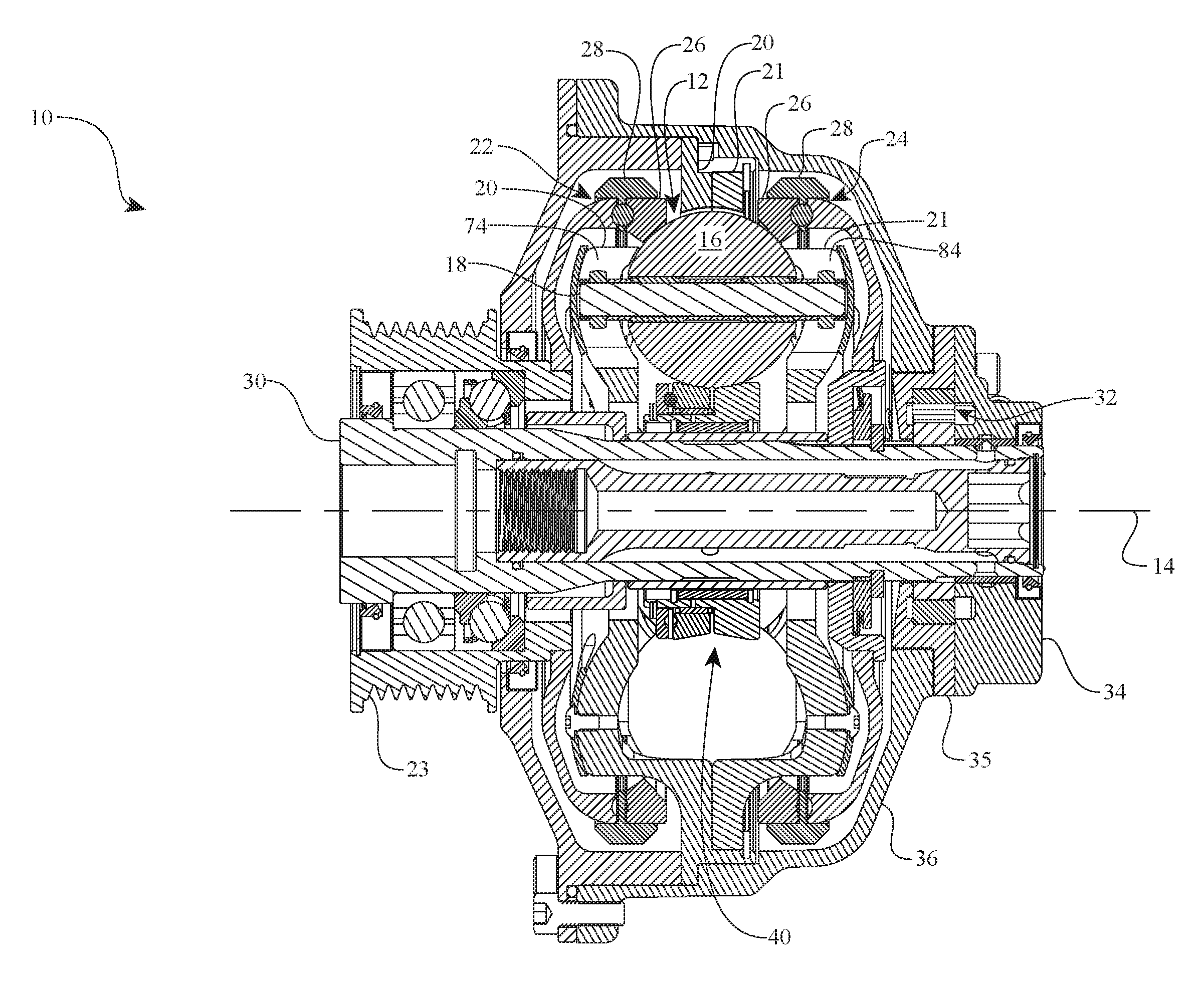
FIG. 1 is a cross-sectional view of an embodiment of a continuously variable accessory drive (CVAD) having a skew control system.
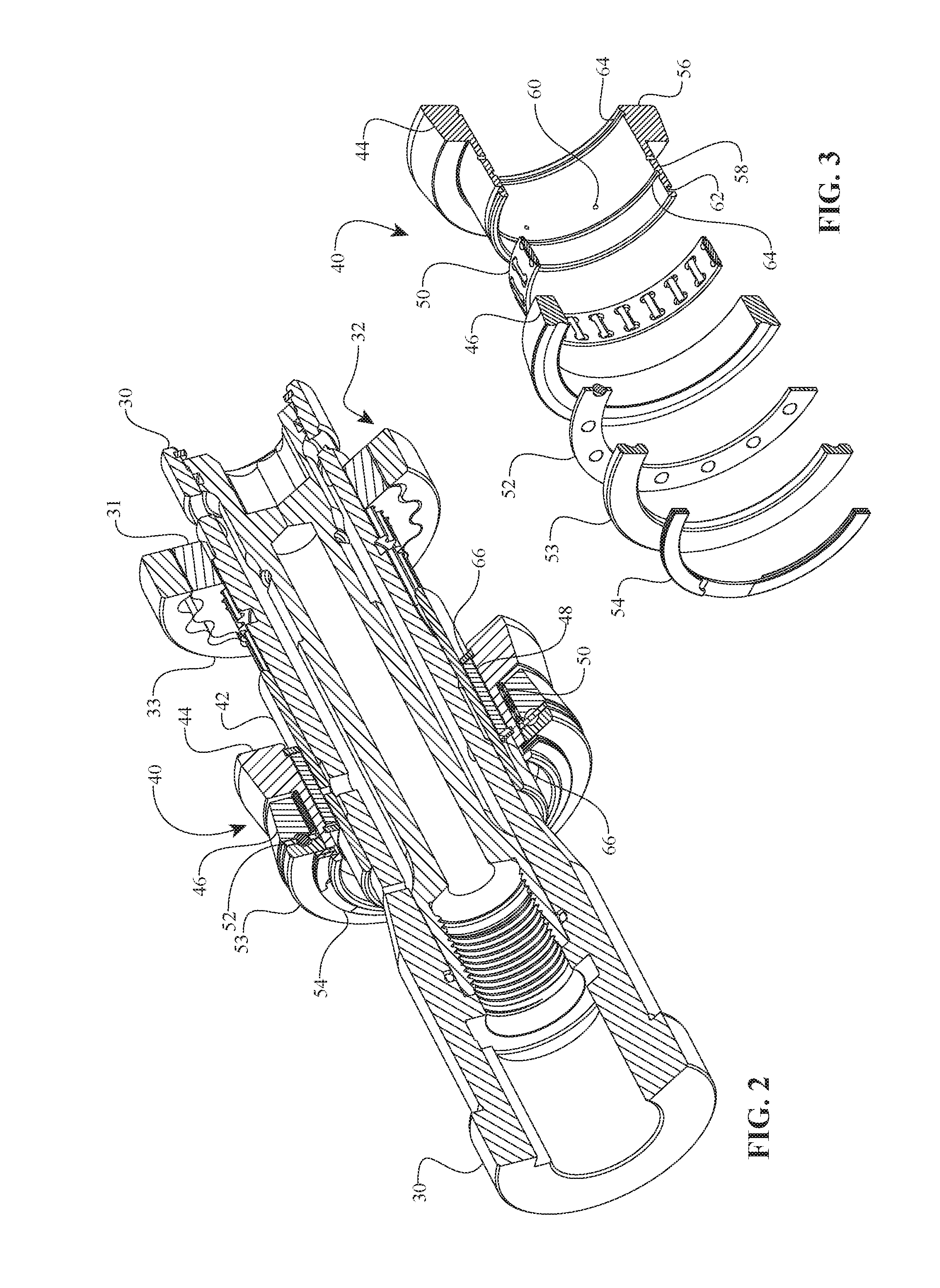
FIG. 2 is a partially cross-sectional perspective view of certain components of the CVAD of FIG. 1.
FIG. 3 is a cross-sectional exploded view of an idler assembly that can be used with the CVAD of FIG. 1.
FIG. 4 is a plan view of a carrier that can be used with the CVAD of FIG. 1.
FIG. 5 is a plan view of a carrier that can be used with the CVAD of FIG. 1.
FIG. 6 is a diagram of one embodiment of an idler assembly that can be used with the CVAD of FIG. 1.
FIG. 7 is a diagram of one embodiment of an idler assembly that can be used with the CVAD of FIG. 1.
FIG. 8 is a diagram of one embodiment of an idler assembly that can be used with the CVAD of FIG. 1.
DETAILED DESCRIPTION OF CERTAIN EMBODIMENTS
The preferred embodiments will be described now with reference to the accompanying figures, wherein like numerals refer to like elements throughout. The terminology used in the descriptions below is not to be interpreted in any limited or restrictive manner simply because it is used in conjunction with detailed descriptions of certain specific embodiments. Furthermore, embodiments of the disclosure can include several novel features, no single one of which is solely responsible for its desirable attributes or which is essential to practicing the embodiments described. Certain CVT embodiments described here are generally related to the type disclosed in U.S. Pat. Nos. 6,241,636; 6,419,608; 6,689,012; 7,011,600; 7,166,052; U.S. patent application Ser. No. 11/243,484; Ser. No. 11/543,311; Ser. No. 12/198,402, Ser. No. 12/251,325; and Patent Cooperation Treaty patent applications PCT/US2007/023315, PCT/IB2006/054911, PCT/US2008/068929, and PCT/US2007/023315, PCT/US2008/074496. The entire disclosures of each of these patents and patent applications are hereby incorporated herein by reference.
As used here, the terms "operationally connected," "operationally coupled," "operationally linked," "operably connected," "operably coupled," "operably linked," and like terms, refer to a relationship (mechanical, linkage, coupling, etc.) between elements whereby operation of one element results in a corresponding, following, or simultaneous operation or actuation of a second element. It is noted that in using said terms to describe certain embodiments, specific structures or mechanisms that link or couple the elements are typically described. However, unless otherwise specifically stated, when one of said terms is used, the term indicates that the actual linkage or coupling may take a variety of forms, which in certain instances will be readily apparent to a person of ordinary skill in the relevant technology. For description purposes, the term "axial" as used here refers to a direction or position along an axis that is parallel to a main or longitudinal axis of a transmission or variator. The term "radial" is used here to indicate a direction or position that is perpendicular relative to a longitudinal axis of a transmission or variator.
It should be noted that reference herein to "traction" does not exclude applications where the dominant or exclusive mode of power transfer is through "friction." Without attempting to establish a categorical difference between traction and friction drives here, generally these may be understood as different regimes of power transfer. Traction drives usually involve the transfer of power between two elements by shear forces in a thin fluid layer trapped between the elements. The fluids used in these applications usually exhibit traction coefficients greater than conventional mineral oils. The traction coefficient (.mu.) represents the maximum available traction forces which would be available at the interfaces of the contacting components and is a measure of the maximum available drive torque. Typically, friction drives generally relate to transferring power between two elements by frictional forces between the elements. For the purposes of this disclosure, it should be understood that the CVTs described here may operate in both tractive and frictional applications. For example, in the embodiment where a CVT is used for a bicycle application, the CVT can operate at times as a friction drive and at other times as a traction drive, depending on the torque and speed conditions present during operation.
Embodiments disclosed here are related to the control of a variator and/or a CVT using generally spherical planets each having a tiltable axis of rotation that can be adjusted to achieve a desired ratio of input speed to output speed during operation. In some embodiments, adjustment of said axis of rotation involves angular displacement of the planet axis in a first plane in order to achieve an angular adjustment of the planet axis in a second plane, wherein the second plane is substantially perpendicular to the first plane. The angular displacement in the first plane is referred to here as "skew," "skew angle," and/or "skew condition". For discussion purposes, the first plane is generally parallel to a longitudinal axis of the variator and/or the CVT. The second plane can be generally perpendicular to the longitudinal axis. In one embodiment, a control system coordinates the use of a skew angle to generate forces between certain contacting components in the variator that will tilt the planet axis of rotation substantially in the second plane. The tilting of the planet axis of rotation adjusts the speed ratio of the variator. The aforementioned skew angle, or skew condition, can be applied in a plane substantially perpendicular to the plane of the page of FIG. 1, for example. Embodiments of transmissions employing certain skew control systems for attaining a desired speed ratio of a variator will be discussed.
One aspect of the torque/speed regulating devices disclosed here relates to drive systems wherein a prime mover drives various driven devices. In this sense, regulating is used to mean varying the transmission ratio to vary the torque or speed of the power being provided to the accessory to correspond with the operating requirements of the accessory being driven from the CVT. The prime mover can be, for example, an electrical motor and/or an internal combustion engine. For purposes of description here, an accessory includes any machine or device that can be powered by a prime mover. For purposes of illustration and not limitation, said machine or device can be a power takeoff device (PTO), pump, compressor, generator, auxiliary electric motor, etc. Accessory devices configured to be driven by a prime mover may also include alternators, water pumps, power steering pumps, fuel pumps, oil pumps, air conditioning compressors, cooling fans, superchargers, turbochargers and any other device that is typically powered by an automobile engine. As previously stated, usually, the speed of a prime mover varies as the speed or power requirements change; however, in many cases the accessories operate optimally at a given, substantially constant speed. Embodiments of the torque/speed regulating devices disclosed here can be used to control the speed of the power delivered to the accessories powered by a prime mover.
For example, in some embodiments, the speed regulators disclosed here can be used to control the speed of automotive accessories driven by a pulley attached to the crankshaft of an automotive engine. Usually, accessories must perform suitably both when the engine idles at low speed and when the engine runs at high speed. Often accessories operate optimally at one speed and suffer from reduced efficiency at other speeds. Additionally, the accessory design is compromised by the need to perform over a large speed range rather than an optimized narrow speed range. In many cases when the engine runs at a speed other than low speed, accessories consume excess power and, thereby, reduce vehicle fuel economy. The power drain caused by the accessories also reduces the engine's ability to power the vehicle, necessitating a larger engine in some cases.
In other situations, inventive embodiments of the torque/speed regulating devices disclosed here can be used to decrease or increase speed and/or torque delivered to the accessories for achieving optimal system performance. In certain situations, embodiments of the torque/speed regulating devices disclosed here can be used to increase speed to the accessories when the prime mover runs at low speed and to decrease speed to the accessories when the prime mover runs at high speed. Thus, the design and operation of accessories can be optimized by allowing the accessories to operate at one, substantially favorable speed, and the accessories need not be made larger than necessary to provide sufficient performance at low speeds. For example, the embodiments of the torque/speed regulating devices disclosed here can enable more power to be extracted from an accessory such as an alternator when the prime mover or engine is running at low idle speed. The accessories can also be made smaller because the torque/speed regulating devices can reduce speed to the accessories when the prime mover runs at high speed, reducing the stress load the accessories must withstand at high rpm. Because the accessories are not subjected to high speeds, their expected service life can increase substantially. In some cases, smoother vehicle operation results because the accessories do not have to run at low or high speed. Further, a vehicle can operate more quietly at high speed because the accessories run at a lower speed.
Embodiments of a continuously variable transmission (CVT), and components and subassemblies thereof, will be described now with reference to FIGS. 1-8. FIG. 1 shows a CVT 10 that can be used in many applications including, but not limited to, continuously variable accessory drives, human powered vehicles (for example, bicycles), light electrical vehicles, hybrid human-, electric-, or internal combustion powered vehicles, industrial equipment, wind turbines, etc. Any technical application that requires modulation of mechanical power transfer between a power input and a power sink (for example, a load) can implement embodiments of the CVT 10 in its power train.
Referring now to FIGS. 1-3, in one embodiment the CVT 10 is provided with a number of traction planet assemblies 12 arranged radially about a longitudinal axis 14. Each traction planet assembly 12 includes a spherical traction planet 16 configured to rotate about a planet axle 18. The planet axle 18 can tilt with respect to the longitudinal axis 14. Ends of the planet axle 18 can be coupled to first and second carriers 20, 21. In one embodiment, the first and second carriers 20, 21 are adapted to rotate with respect to each other. The CVT 10 can be provided with a first traction ring assembly 22 in contact with each of the traction planets 16. In one embodiment, the first traction ring assembly 22 is adapted to receive a power input from a drive pulley 23. The CVT 10 can be provided with a second traction ring assembly 24 in contact with each of the traction planets 16. In one embodiment, the first and second traction ring assemblies 22, 24 are each provided with a traction ring 26 and an axial force generator assembly 28. In some embodiments, the axial force generator assembly 28 can include a tone wheel configured to cooperate with, for example, a speed sensor (not shown). The CVT 10 is provided with a shaft 30 arranged along the longitudinal axis 14. The shaft 30 can be configured to transfer power to an accessory (not shown), such as an alternator. The shaft 30 is configured to drive, among other things, a pump 32. In one embodiment, the pump 32 is a gerotor type pump having an inner driven gear 31 coupled to an outer gear 33. The inner driven gear 31 is coupled to the shaft 30. The pump 32 is in fluid communication with a lubricant manifold 34. The lubricant manifold 34 is attached to a pump cavity 35. The pump cavity 35 and the lubricant manifold 34 substantially enclose the pump 32. The pump cavity 35 is coupled to a housing 36. The housing 36 substantially encloses and supports components of the CVT 10. The lubricant manifold 34, the pump cavity 35, and the shaft 30 are provided with a number of passages that are appropriately arranged to introduce a lubricant from a reservoir (not shown) into the pump 32 and deliver the lubricant to internal components of the CVT 10. In one embodiment, the reservoir is integral with the housing 36. In some embodiments, the reservoir can be remotely located.
In one embodiment, the CVT 10 is provided with an idler assembly 40 arranged radially inward of, and in contact with, each of the traction planets 16. The idler assembly 40 couples to a sleeve 42. The sleeve 42 is coaxial with, and surrounds, the shaft 30. In some embodiments, the sleeve 42 can be integral to the shaft 30. The sleeve 42 can be made of a different material than the shaft 30. For example, the sleeve 42 can be made of a material that has properties appropriate for a bearing race or a journal. In one embodiment, the idler assembly 40 includes a first rolling element 44 operably coupled to a second rolling element 46. The first rolling element 44 is radially supported on the sleeve 42 by a bearing 48. The bearing 48 can be a needle roller bearing, for example. The second rolling element 46 is radially supported by a bearing 50. The bearing 50 can be a needle roller bearing, for example. The second rolling element 46 is supported in the axial direction by a bearing 52. The bearing 52 can be a ball bearing, for example. The bearing 52 is coupled to a race 53. The race 53 is attached to the first rolling element 44 with, for example, a clip 54. The bearing 52 is positioned in a manner to balance the axial force applied to the first rolling element 44 with the axial force applied to the second rolling element 46.
During operation of the CVT 10, the first and second rolling elements 44, 46 rotate about the longitudinal axis 14. The first and second rolling elements 44, 46 each rotate at a speed corresponding to the tilt angle of the planet axle 18 with respect to the longitudinal axle 14. Under some operating conditions, for example when the planet axle 18 is substantially parallel to the longitudinal axis 14, the speed of the first rolling element 44 is substantially equal to the speed of the second rolling element 46. Under other operating conditions, the speed of the first rolling element 44 can be higher than the speed of the second rolling element 46. Under yet other operating conditions, the speed of the first rolling element 44 can be lower than the speed of the second rolling element 46. During operation of the CVT 10, the difference in speed between the first and second rolling elements 44, 46 is transmitted to the bearing 52. This is advantageous since the speed difference between the first and second rolling elements 44, 46 is typically small. It is well known that parasitic losses from bearings are related to the speed and load at which a bearing operates. Since the bearing 52 typically operates under relatively high axial loads, reducing the speed at which the bearing 52 operates serves to reduce the parasitic loss of the bearing 52.
Referring now specifically to FIG. 3, in one embodiment the first rolling element 44 is a generally cylindrical body having a ring 56 formed on one end. The first rolling element 44 is provided with a shoulder 58 extending from the ring 56. The shoulder 58 has a number of holes 60 arranged radially about the circumference of the cylindrical body. The holes 60 can facilitate the flow of lubricant to, for example, the bearing 50. In some embodiments, the holes 60 facilitate the flow of lubricant to the contacting surfaces between the traction planets 16 and the first and second rolling elements 44, 46. The shoulder 58 is provided with a groove 62 formed on the outer periphery of the cylindrical body. The groove 62 is adapted to receive the clip 54. The first rolling element 44 is provided with grooves 64 on the inner circumference of the cylindrical body. The grooves 64 are adapted to receive, for example, clips 66 (FIG. 2). The clips 66 facilitate the retention of the bearing 48 (FIG. 2) with respect to the first rolling element 44.
Turning now to FIG. 4, in one embodiment the first carrier 20 is a substantially bowl-shaped body having a central bore 72. The bowl-shaped body can be provided with a number of guide slots 74 arranged angularly about the central bore 72. The guide slots 74 are aligned with a radial construction line 76 when viewed in the plane of the page of FIG. 4. The guide slots 74 are adapted to receive one end of the planet axle 18. The bowl-shaped body is provided with a flange 77 formed about the outer periphery. The flange 77 can be adapted to attach to the housing 36.
Referring now to FIG. 5, in one embodiment the second carrier 21 is a substantially bowl-shaped body having a central bore 82. The bowl-shaped body can be provided with a number of guide slots 84 arranged angularly about the central bore 82. Each guide slot 84 is sized to accommodate the coupling of the second carrier 21 to the planet axle 18. The guide slots 84 are angularly offset from the radial construction line 76 when viewed in the plane of the page of FIG. 5. The angular offset can be approximated by an angle 88. The angle 88 is formed between the radial construction line 76 and a construction line 90. The construction line 90 substantially bisects the guide slot 84 when viewed in the plane of the page of FIG. 5. In some embodiments, the angle 88 is between 3 degrees and 45 degrees. A low angle 88 would provide faster shift rates in a given application but rotation of the carrier 21 must be controlled over a very small range. A high angle 88 would provide slower shift rates in a given application but rotation of carrier 21 would be controlled over a larger range. In effect, a low angle 88 produces a highly responsive transmission ratio change but potentially more difficult to control or stabilize, while a high angle can be less responsive in transmission ratio change but easy to control by comparison. In some embodiments, where it is desirable to have high speed, fast shift rates, the angle 88 can be, for example, 10 degrees. In other embodiments, where it is desirable to have slower speed, precise control of transmission ratio, the angle 88 can be about 30 degrees. However, the said values of the angle 88 are provided as an illustrative example, and the angle 88 can be varied in any manner a designer desires. In some embodiments, the angle 88 can be any angle in the range of 10 to 25 degrees including any angle in between or fractions thereof. For example, the angle can be 10, 11, 12, 13, 14, 15, 16, 17, 18, 19, 20, 21, 22, 23, 24, 25, or any portion thereof. In other embodiments, the angle 88 can be 20 degrees. In one embodiment, the guide slots 84 can be arranged so that the construction line 90 is radially offset from a construction line 91 by a distance 92. The construction line 91 is parallel to the construction line 90 and intersects the center of the bowl-shaped body.
In one embodiment, the second carrier 21 is coupled to a clevis 94. The clevis 94 can be accessed through an opening (not shown) in the housing 36 to facilitate the coupling of the clevis 94 to an actuator (not shown). During operation of the CVT 10, a change in transmission ratio can be accomplished by rotating the second carrier 21 with respect to the first carrier 20. A rotation of the second carrier 21 can be accomplished by moving the clevis 94 with the actuator.
Referring now to FIG. 6, in one embodiment an idler assembly 100 includes a spherical traction planet 101. The spherical traction planet 101 can be provided with a tiltable axis of rotation (not shown). The idler assembly 100 includes first and second rolling elements 102, 103, respectively. In some embodiments, the first rolling element 102 can be coupled to at least one bearing 104 at a radially inward location. In other embodiments, the bearing 104 is not used. The second rolling element 103 can be coupled to at least one bearing 105 at a radially inward location. The bearing 105 is supported by the first rolling element 102. The second rolling element 103 can be axially coupled to the first rolling element 102 with a bearing 106. In some embodiments, the bearing 106 can be an angular contact bearing, in such cases the bearing 105 can be removed. The bearing 106 is coupled to a shoulder 107 attached to the first rolling element 102. In one embodiment, the shoulder 107 is integral to the first rolling element 102. In other embodiments, the shoulder 107 is a separate component that is fixedly attached to the first rolling element 102. Each of the first and second rolling elements 102, 103 are provided with contact surfaces 109, 110, respectively. The contact surfaces 109, 110 are in contact with the traction planet 101. The contact surfaces 109, 110 are angled with respect to a longitudinal axis 111 at an angle 112 when viewed in the plane of the page of FIG. 6. In some embodiments, the angle 112 can be any angle in the range of 0 to 45 degrees including any angle in between or fractions thereof. For example, the angle can be 0, 1, 2, 3, 4, 5, 6, 7, 8, 9, 10, 11, 12, 13, 14, 15, 16, 17, 18, 19, 20, 21, 22, 23, 24, 25, 26, 27, 28, 29, 30, 31, 32, 33, 34, 35, 36, 37, 38, 39, 40, 41, 42, 43, 44, 45 or any portion thereof. In other embodiments, the angle 112 can be 10 degrees. In some embodiments, the first rolling element 102 is configured to receive an input power.
Passing now to FIG. 7, in one embodiment an idler assembly 120 can include first and second rolling elements 121, 122, respectively. The first and second rolling elements 121, 122 are each coupled to a bearing 123. The bearings 123 can be attached to a sleeve 124 with, for example, clips 125. The first and second rolling elements 121, 122 are each provided with a contact surface 126. The contact surfaces 126 are in contact with the traction planet 101. The contact surfaces 126 are formed at the angle 112 relative to the longitudinal axis 111 when viewed in the plane of the page of FIG. 7.
Referring now to FIG. 8, in one embodiment an idler assembly 130 can include first and second rolling elements 132, 133, respectively. The first and second rolling elements 132, 133 are each coupling to a bearing 136. The bearing 136 can be provided with a cage 137. The first rolling element 132 has an extension 134. The extension 134 coupled to the bearing 136. In one embodiment, the bearing 136 is an angular contact bearing. The first rolling element 132 is provided with a contact surface 139. The contact surface 139 is in contact with the traction planet 101. The second rolling element 133 is provided with a contact surface 140. The contact surfaces 139, 140 are formed at the angle 112 relative to the longitudinal axis 111 when viewed in the plane of the page of FIG. 8.
It should be noted that the description above has provided dimensions for certain components or subassemblies. The mentioned dimensions, or ranges of dimensions, are provided in order to comply as best as possible with certain legal requirements, such as best mode. However, the scope of the embodiments described herein are to be determined solely by the language of the claims, and consequently, none of the mentioned dimensions is to be considered limiting on the embodiments, except in so far as any one claim makes a specified dimension, or range of thereof, a feature of the claim.
The foregoing description details certain embodiments of the disclosure. It will be appreciated, however, that no matter how detailed the foregoing appears in text, the disclosure can be practiced in many ways. As is also stated above, it should be noted that the use of particular terminology when describing certain features or aspects of the disclosure should not be taken to imply that the terminology is being re-defined herein to be restricted to including any specific characteristics of the features or aspects of the disclosure with which that terminology is associated.
* * * * *
D00000
D00001
D00002
D00003
D00004
XML
uspto.report is an independent third-party trademark research tool that is not affiliated, endorsed, or sponsored by the United States Patent and Trademark Office (USPTO) or any other governmental organization. The information provided by uspto.report is based on publicly available data at the time of writing and is intended for informational purposes only.
While we strive to provide accurate and up-to-date information, we do not guarantee the accuracy, completeness, reliability, or suitability of the information displayed on this site. The use of this site is at your own risk. Any reliance you place on such information is therefore strictly at your own risk.
All official trademark data, including owner information, should be verified by visiting the official USPTO website at www.uspto.gov. This site is not intended to replace professional legal advice and should not be used as a substitute for consulting with a legal professional who is knowledgeable about trademark law.