Elevated flooring system
Rosan Fe
U.S. patent number 10,196,826 [Application Number 15/954,391] was granted by the patent office on 2019-02-05 for elevated flooring system. This patent grant is currently assigned to EverBlock Systems, LLC. The grantee listed for this patent is EverBlock Systems, LLC. Invention is credited to Arnon Rosan.


| United States Patent | 10,196,826 |
| Rosan | February 5, 2019 |
Elevated flooring system
Abstract
An elevated flooring system includes floor modules each having first and second module surfaces and module ribs. First module surfaces may be solid or include holes for drainage. Module ribs provide structural support and define at least one module receiving space accessible from the second module surface. Block(s) include extensions protruding from a first block surface and are dimensioned to fit within a corresponding module receiving space. Each block includes block ribs providing support and defining at least one block receiving space accessible from a second block surface. Interfacing member(s) include a body correspondingly dimensioned to fit within a block receiving space and leg(s) extending from the body and dimensioned to fit within a hole on a first module surface. Floor modules may be joined adjacently and interfacing members, blocks and floor modules are stackable to provide a modular and customizable flooring system of different and varying heights.
| Inventors: | Rosan; Arnon (New York, NY) | ||||||||||
|---|---|---|---|---|---|---|---|---|---|---|---|
| Applicant: |
|
||||||||||
| Assignee: | EverBlock Systems, LLC (New
York City, NY) |
||||||||||
| Family ID: | 65200072 | ||||||||||
| Appl. No.: | 15/954,391 | ||||||||||
| Filed: | April 16, 2018 |
| Current U.S. Class: | 1/1 |
| Current CPC Class: | E04F 15/02452 (20130101); E04F 15/02133 (20130101); E04F 15/02417 (20130101); E04H 3/28 (20130101); E04F 2290/02 (20130101); E04F 15/105 (20130101); E04F 2201/0517 (20130101); E04F 2290/00 (20130101); E04F 2201/0138 (20130101); E04F 2201/021 (20130101); E04F 15/102 (20130101) |
| Current International Class: | E04F 15/024 (20060101); E04H 3/28 (20060101); E04F 15/10 (20060101) |
References Cited [Referenced By]
U.S. Patent Documents
| D879455 | February 1908 | Frost |
| 968512 | August 1910 | Praray |
| 1689107 | October 1928 | Bradley |
| 1977496 | October 1934 | Snyder et al. |
| D148930 | March 1948 | Hickman |
| 3005282 | October 1961 | Christiansen |
| D194083 | November 1962 | Brach |
| 3162973 | December 1964 | Godtfred |
| 3310919 | March 1967 | Bue et al. |
| 3349533 | October 1967 | Gregoire |
| 3382632 | May 1968 | Grofcsik |
| 3397496 | June 1968 | Sohns |
| D215582 | October 1969 | Bogan |
| 3487756 | January 1970 | Glaza et al. |
| 3859000 | January 1975 | Zeif |
| 3964221 | June 1976 | Berquist |
| D243855 | March 1977 | Hynes |
| 4026086 | May 1977 | Langley |
| 4067155 | January 1978 | Ruff et al. |
| 4198795 | April 1980 | Barnidge |
| 4238181 | December 1980 | Dannels |
| 4254574 | March 1981 | Stock |
| 4436779 | March 1984 | Menconi et al. |
| 4468910 | September 1984 | Morrison |
| 4629358 | December 1986 | Springston et al. |
| 4630417 | December 1986 | Collier |
| 4840825 | June 1989 | Aristodimou |
| D304042 | October 1989 | Poulson |
| 4883503 | November 1989 | Fish |
| 4901485 | February 1990 | Menchetti et al. |
| 4988131 | January 1991 | Wilson et al. |
| D317482 | June 1991 | Michaelsen |
| 5022200 | June 1991 | Wilson et al. |
| 5061218 | October 1991 | Garage |
| 5070662 | December 1991 | Niese |
| D326874 | June 1992 | Dideriksen |
| D331696 | December 1992 | Graham |
| 5263289 | November 1993 | Boyd |
| 5295341 | March 1994 | Kajiwara |
| 5364204 | November 1994 | MacLeod |
| 5400554 | March 1995 | Lo |
| 5402609 | April 1995 | Kelley |
| 5403063 | April 1995 | Sjostedt et al. |
| 5407342 | April 1995 | Boucher et al. |
| 5427558 | June 1995 | Knudsen et al. |
| 5434355 | July 1995 | Sho |
| 5469999 | November 1995 | Phirippidis |
| D368939 | April 1996 | Fredericksen |
| 5509244 | April 1996 | Bentzon |
| D376281 | December 1996 | Robertson |
| D378837 | April 1997 | Olsen |
| 5630300 | May 1997 | Chen |
| 5630304 | May 1997 | Austin |
| 5653551 | August 1997 | Seaux |
| 5657598 | August 1997 | Wilbs et al. |
| 5666772 | September 1997 | Betty |
| D387431 | December 1997 | Tremblay |
| D391110 | February 1998 | Graebe |
| 5777266 | July 1998 | Herman et al. |
| 5787654 | August 1998 | Drost |
| 5833386 | November 1998 | Rosan et al. |
| 5865007 | February 1999 | Bowman |
| D409676 | May 1999 | Toft |
| 5904015 | May 1999 | Chen |
| 5950378 | September 1999 | Council |
| D415471 | October 1999 | Henry |
| 5966889 | October 1999 | Zinner |
| D416143 | November 1999 | Ragan |
| 5987840 | November 1999 | Leppert |
| 5992106 | November 1999 | Carling et al. |
| 6032428 | March 2000 | Rosan |
| D426933 | June 2000 | Redfern |
| 6093469 | July 2000 | Callas |
| 6094882 | August 2000 | Pervan |
| 6098354 | August 2000 | Skandis |
| 6128881 | October 2000 | Bue et al. |
| D437832 | February 2001 | Henry |
| 6187394 | February 2001 | Johnson et al. |
| 6189283 | February 2001 | Bentley et al. |
| 6200187 | March 2001 | Olsen et al. |
| 6202565 | March 2001 | Henry |
| 6220785 | April 2001 | Kennedy et al. |
| 6245415 | June 2001 | Keller et al. |
| D445148 | July 2001 | McIntosh |
| 6282858 | September 2001 | Swick |
| 6293062 | September 2001 | Chen |
| D449170 | October 2001 | Kim |
| 6330770 | December 2001 | Fukunaga |
| D456533 | April 2002 | Moller |
| D457971 | May 2002 | Schrader |
| 6434897 | August 2002 | Sievers et al. |
| 6455127 | September 2002 | Valtanen |
| D463866 | October 2002 | Jang |
| 6481036 | November 2002 | Duvall |
| 6499410 | December 2002 | Berardi |
| D468839 | January 2003 | Bland |
| 6511257 | January 2003 | Seaux et al. |
| 6550192 | April 2003 | Nelson et al. |
| 6554604 | April 2003 | Schmidt |
| 6564522 | May 2003 | Chiu-Ying |
| 6584739 | July 2003 | Zeif |
| 6649110 | November 2003 | Seaux et al. |
| 6662508 | December 2003 | Else |
| 6684582 | February 2004 | Peart et al. |
| 6685388 | February 2004 | Webster et al. |
| 6695527 | February 2004 | Seaux et al. |
| 6719551 | April 2004 | Polk, Jr. |
| 6747212 | June 2004 | Henry |
| 6751912 | June 2004 | Stegner et al. |
| D498307 | November 2004 | Zimmerle |
| 6869558 | March 2005 | Polk, Jr. |
| 6878881 | April 2005 | Henry |
| 6900547 | May 2005 | Polk, Jr. |
| 6909373 | June 2005 | Power et al. |
| D515223 | February 2006 | Geffe |
| 7080491 | July 2006 | Shreiner et al. |
| 7145079 | December 2006 | Henry |
| 7208219 | April 2007 | Polk, Jr. |
| D552190 | October 2007 | Glickman |
| 7299592 | November 2007 | Moller |
| 7303800 | December 2007 | Rogers |
| 7309836 | December 2007 | Lubanski |
| 7332672 | February 2008 | Henry |
| D563323 | March 2008 | Henry |
| 7340865 | March 2008 | Vanderhoef |
| 7360343 | April 2008 | Spransy |
| 7385139 | June 2008 | Lubanski |
| 7401441 | July 2008 | Zimmerle |
| 7413374 | August 2008 | Rogers et al. |
| D581553 | November 2008 | Cooper |
| D583771 | December 2008 | Lubanski |
| 7487622 | February 2009 | Wang |
| 7516587 | April 2009 | Barlow |
| 7531746 | May 2009 | Henry |
| 7546707 | June 2009 | Digennaro |
| 7571573 | August 2009 | Moller |
| 7592547 | September 2009 | Lubanski |
| 7607265 | October 2009 | Curry et al. |
| 7621092 | November 2009 | Groeke et al. |
| 7674980 | March 2010 | Lubanski |
| 7779595 | August 2010 | Polk, Jr. |
| 7795535 | September 2010 | Lubanski |
| 7827750 | November 2010 | Sondermann |
| 7837917 | November 2010 | Polk, Jr. |
| 7838772 | November 2010 | Lubanski |
| 7842226 | November 2010 | Polk, Jr. |
| 7914228 | March 2011 | Rapaz |
| 7923095 | April 2011 | Polk, Jr. |
| 7931845 | April 2011 | Polk, Jr. |
| 7939759 | May 2011 | Henry |
| 7943851 | May 2011 | Lubanski |
| 7955550 | June 2011 | Polk, Jr. |
| 7959450 | June 2011 | Wang et al. |
| 8070471 | December 2011 | Polk, Jr. |
| D652952 | January 2012 | Angel |
| 8119914 | February 2012 | Lubanski |
| 8141314 | March 2012 | Rosan |
| D667144 | September 2012 | Else |
| 8288652 | October 2012 | Lubanski |
| 8309850 | November 2012 | Henry |
| D677800 | March 2013 | Cetindag |
| 8397466 | March 2013 | Jenkins |
| 8413399 | April 2013 | Kelley, Jr. |
| 8414217 | April 2013 | Rosan |
| D686676 | July 2013 | Telford |
| D689954 | September 2013 | Rya |
| D695534 | December 2013 | Matasovi |
| D701973 | April 2014 | Holcomb |
| 8756882 | June 2014 | Vachon |
| 8791363 | July 2014 | Lubanski |
| D717248 | November 2014 | Coffman |
| D717379 | November 2014 | Deutsch |
| D717971 | November 2014 | Saunders |
| 8936374 | January 2015 | Royse |
| D724760 | March 2015 | Saunders |
| D727884 | April 2015 | Fathollahi |
| 9010060 | April 2015 | Rapaz |
| 9051739 | June 2015 | Rosan |
| 9059574 | June 2015 | Coffman |
| D738063 | September 2015 | Angel |
| 9187895 | November 2015 | Rodriguez |
| 9206597 | December 2015 | Marsh |
| 9212746 | December 2015 | McDowell |
| D746605 | January 2016 | Matasovic |
| D748415 | February 2016 | DeRoeck |
| D749680 | February 2016 | Lin |
| 9249570 | February 2016 | Jean |
| D751153 | March 2016 | Lacroix |
| D753774 | April 2016 | Proulx |
| 9337586 | May 2016 | McDowell |
| 9506255 | November 2016 | Jones |
| D776205 | January 2017 | Facey et al. |
| D783731 | April 2017 | Rosan |
| D786586 | May 2017 | Rosan |
| 9673601 | June 2017 | Coffman |
| D791885 | July 2017 | Rosan |
| D800846 | October 2017 | Rosan |
| D809162 | January 2018 | Rosan |
| 2001/0002523 | June 2001 | Chen |
| 2002/0059764 | May 2002 | Schluter |
| 2002/0084543 | July 2002 | Buja |
| 2002/0192024 | December 2002 | Webster |
| 2003/0089049 | May 2003 | Scissom |
| 2003/0093964 | May 2003 | Bushey et al. |
| 2003/0113162 | June 2003 | Seaux et al. |
| 2003/0197296 | October 2003 | Krassilnikov |
| 2004/0005430 | January 2004 | Rogers |
| 2004/0093811 | May 2004 | Oakey et al. |
| 2004/0139671 | July 2004 | Owen |
| 2004/0216250 | November 2004 | Dumiao et al. |
| 2004/0258869 | December 2004 | Walker |
| 2006/0070314 | April 2006 | Jenkins et al. |
| 2006/0130378 | June 2006 | Rybalov |
| 2006/0159793 | July 2006 | Hahn et al. |
| 2006/0265975 | November 2006 | Geffe |
| 2007/0079569 | April 2007 | Curry et al. |
| 2007/0102243 | May 2007 | Ruminski |
| 2007/0108668 | May 2007 | Hutchinson et al. |
| 2007/0113492 | May 2007 | Dickey et al. |
| 2007/0137129 | June 2007 | Sondermann |
| 2007/0261317 | November 2007 | Moller, Jr. |
| 2007/0280782 | December 2007 | Rogers |
| 2008/0127593 | June 2008 | Janesky |
| 2008/0141601 | June 2008 | Mead |
| 2009/0071083 | March 2009 | Huang |
| 2009/0133349 | May 2009 | Sondermann |
| 2009/0165414 | July 2009 | Burk |
| 2009/0217611 | September 2009 | Schrader |
| 2009/0308002 | December 2009 | Curry et al. |
| 2010/0252788 | October 2010 | Wickwire |
| 2010/0300023 | December 2010 | Rosan |
| 2011/0023389 | February 2011 | Myers |
| 2011/0097489 | April 2011 | Kerr et al. |
| 2011/0193253 | August 2011 | Polk et al. |
| 2011/0277926 | November 2011 | Polk, Jr. |
| 2012/0266549 | October 2012 | Rosan |
| 2013/0037322 | February 2013 | Lubanski |
| 2013/0319796 | December 2013 | Davis |
| 2014/0020927 | January 2014 | Coffman |
| 2014/0137505 | May 2014 | Jean |
| 2015/0007508 | January 2015 | Valtanen |
| 2015/0096250 | April 2015 | Lam |
| 2015/0361675 | December 2015 | Cerny |
| 2016/0017547 | January 2016 | Bordelon |
| 2016/0076204 | March 2016 | McDowell |
| 2016/0301161 | October 2016 | McDowell |
| 2017/0030086 | February 2017 | Rodriguez Lopez |
| 3445071 | Nov 1987 | DE | |||
| 20209502 | Oct 2002 | DE | |||
| 1913213 | Apr 2008 | EP | |||
| 2699729 | Dec 2016 | EP | |||
| 2256023 | Nov 1992 | GB | |||
| 2483412 | Oct 2015 | GB | |||
| WO9220885 | Nov 1992 | WO | |||
| WO2017042734 | Mar 2017 | WO | |||
Other References
|
MegaDeck Photos--Protective Maiting and Temporary Roadway Gallery (online). dated Sep. 26, 2011. Retrieved from Internet Apr. 4, 2017. URL: https://web.archive.org/web/20110926113010/http:www.megadeckrigmats.com/m- egadeck-gallery.php (3 pages). cited by applicant . MegaDeck HD--Rig Mat systems (on-line), dated Jun. 25, 2016. Retrieved from Internet Apr. 4, 2017, URL:https://web.archive.org/web/20160625003824//http://www.megadeckrigmat- s.com/what-is-megabeck.php (3 pages) cited by applicant . SignaRoad--The Most Versatile Mat on the Market (on-line), dated May 13, 2016. Retrieved from Internet Apr. 4, 2017, URL: https:/web.archive.org/web2016051320056/http:/www.megadeckrigmats.com/Sig- naRoadphp (3 pages). cited by applicant . Matting/Portable Roadways (on-line), dated Mar. 22, 2013. Retrieved from Internet Apr. 4, 2017, URL: https:/web.archive.org/web/20130322122659/http://coleservicesnj.com/matti- ng_rentals.html (1 page). cited by applicant . Rain for Rent SolidGround Traction Mats (on-line), dated Jan. 30, 2013, Retrieved from Internet Apr. 4, 2017, URL: https:/web.archive.org/web/20130130023451/http:/www.rainforrent.com/Solid- GroundTM-Traction-Mats.aspx (1 page). cited by applicant . Lego Classic website, May 31, 2016, (1 page). cited by applicant . Mega Bloks website, May 31, 2016. cited by applicant . I Want That EverBlock: Announced Mar. 9, 2015 [online], site visited May 20, 2016. Available from Internet URL: https://www.youtube.com/watch?v=ac8s71mO8Q0. cited by applicant . Modular Plastic Blocks: Announced Jun. 18, 2015 [online], site visited May 20, 2017. Available from Internet URL:http//www.everblocksystems.com. cited by applicant. |
Primary Examiner: Ford; Gisele D
Attorney, Agent or Firm: Metz Lewis Brodman Must O'Keefe LLC
Claims
What is claimed is:
1. A flooring system, comprising: at least one block having a first block surface, an opposite second block surface, and at least one extension protruding from said first block surface by a predetermined height; a plurality of floor modules each having a smooth first module surface, an opposite second module surface, at least one perimetric side extending between said first and second module surfaces, and at least one connector extending outwardly from said at least one perimetric side, each of said at least one connector shaped to engage a corresponding connector of a different one of said plurality of floor modules; at least one of said plurality of floor modules further including a plurality of holes formed in said first module surface and dimensioned to receive an interfacing member; said second module surface of each of said plurality of floor modules including a plurality of module ribs configured to collectively define at least one module receiving space dimensioned to receive said at least one extension of said at least one block; and said at least one block and said plurality of floor modules being stackable in a vertical direction to create an elevated flooring system.
2. The flooring system as recited in claim 1, further comprising at least one interfacing member having a body and at least one leg extending from said body, said at least one leg dimensioned to be inserted and received in a corresponding one of said plurality of holes of said first module surface.
3. The flooring system as recited in claim 2, wherein said at least one interfacing member is selectively attachable to said first module surface of said flooring module.
4. The flooring system as recited in claim 2, wherein said plurality of holes are collectively configured to accommodate various placements of said at least one interfacing member on said first module surface.
5. The flooring system as recited in claim 2, wherein said at least one block having a plurality of block ribs formed in said second block surface and configured to collectively define at least one block receiving space dimensioned to receive at least a portion of said body of said at least one interfacing member.
6. The flooring system as recited in claim 1, wherein at least one of said plurality of floor modules are positionable on a supporting surface.
7. The flooring system as recited in claim 1, wherein said at least one block is positionable on a supporting surface.
8. The flooring system as recited in claim 1, further comprising at least one layer, each layer formed of different ones of said plurality of floor modules laterally connected to adjacent ones of said plurality of floor modules, said at least one connector of each of said plurality of floor modules configured to engage said at least one connector of an adjacent one of said plurality of floor modules.
9. The flooring system as recited in claim 8, wherein said flooring system includes multiple layers spaced apart in the vertical direction by said at least one block.
10. The flooring system as recited in claim 1, further comprising a plurality of blocks each having a plurality of block ribs integrally formed in said second block surface and configured to collectively define at least one block receiving space dimensioned to receive at least a portion of said at least one extension of a different one of said plurality of blocks.
11. The flooring system as recited in claim 1, wherein said connector is one of a first connector and a second connector, wherein said first connector having a loop structure and defining an opening between a distal portion of said loop structure and said at least one side of said floor module, said second connector having an extension of a predetermined length and a terminal portion protruding from said extension, wherein said opening of said first connector is dimensioned to receive and retain said terminal portion of said second connector.
12. The flooring system as recited in claim 11, wherein at least a part of said distal portion of said first connector includes a planar configuration.
13. The flooring system as recited in claim 11, wherein each of said plurality of floor modules includes at least one first connector and at least one second connector.
14. The flooring system as recited in claim 13, wherein each of said plurality of floor modules includes a plurality of perimetric sides, each of said sides having at least one of said first and second connectors.
15. The flooring system as recited in claim 14, wherein opposing sides of one of said floor modules have different ones of said first and second connectors.
16. The flooring system as recited in claim 1, wherein said first module surface of at least one of said plurality of floor modules is continuous.
17. The flooring system as recited in claim 1, wherein said first module surface includes at least one indicia.
18. The flooring system as recited in claim 17, wherein said at least one indicia is formed in said first module surface by in-mold labeling.
19. The flooring system as recited in claim 1, wherein each of said plurality of floor modules includes at least one channel extending through said second module surface and dimensioned to receive at least one cord.
20. The flooring system as recited in claim 1, wherein said at least one block further comprising at least one bore extending through said block and said first and second block surfaces.
Description
FIELD OF THE INVENTION
This invention relates to flooring systems and more particularly, to modular flooring systems having at least one elevated layer and providing variation in both the lateral and vertical dimensions.
BACKGROUND
Events such as concerts, weddings, dances, graduations and parties often require or benefit from temporary flooring. They are often held in places with uneven flooring or flooring that is unsuitable for pedestrian traffic, dancing or other purposes of the event. For instance, many events require a stage, dais, or other type of raised platform where attention may be focused during the event. Such raised platforms are placed on the ground or other floor covering, and are often unstable even when the supporting surface is relatively flat since they are not secured to the ground or floor. Further, these raised platforms are only available in certain predetermined sizes and heights, thereby limiting the amount of elevation that can be achieved with the platform. This likewise limits the creativity and utility of the event space and accommodations. In addition, events may be held on surfaces that are uneven or unstable such as grass, dirt or uneven pavement outdoors that can be hazardous or dirty when walking or dancing, such as from tripping or slipping in mud, loose dirt, uncovered roots, rocks, clots of dirt, etc. Tents may be erected to protect guests from the sun and inclement weather, but they provide only the barest of protections to the ground or floor, and those are at a spaced apart distance. Indoor locations may also have unsuitable flooring, which may be tilted, uneven or unfinished, such as in basements, making navigation problematic unless one is careful.
Modular flooring systems are therefore commonly employed for events to create a temporary, artificial floor that is safer to walk on than the underlying ground or floor. Such modular flooring systems provide stability and can also be used to create a desired aesthetic effect, such as of tiles or borders. They often require the placement and interlocking of individual floor modules to create the overall floor covering, which can then be disassembled and removed when the event is over without damage to the underlying ground or floor. However, these modular flooring systems only cover the floor, and do not address platforms or other raised areas.
Known modular flooring systems also fail to address furniture such as stages, tables, chairs, podiums and other equipment that are supplied separately and placed on the flooring system during the event. Usually the flooring system is smooth to allow for unimpeded locomotion, but this can also mean the furniture may shift on the flooring system during use, which can be dangerous if it occurs during use. Further, any incline in the installed flooring system may lead to sliding of the furniture once placed. This danger is augmented when additional equipment or furniture is layered, such as a podium placed on top of a stage.
Accordingly, there remains room for improvement in the field of modular floor coverings. Specifically, it would be beneficial to have a modular flooring system that is both temporary and customizable to achieve any desired dimension and elevation, while also affording stability.
SUMMARY
An elevated flooring system is disclosed which can be used to cover ground, provide stable floor covering and create elevated portions for further flooring levels of differing heights. The present invention may be used to provide flooring for indoor and outdoor events, within tents, in basements and other areas where the ground or floor may benefit from a more stable surface. The present invention also allows for the creation of a stage, dais, platform(s), walls, stairs, and other elements that may be desired to be located at a distance above the underlying floor or ground. The elevated flooring system is entirely modular so it is fully customizable. The elevated flooring system may be expanded in any direction, including vertically, to create any number of elevated features at any desired height(s). It also permits the formation of multiple layers of flooring, adding versatility and flexibility in design.
The elevated flooring system includes at least one floor module that forms a substantially planar surface of the flooring system. Floor modules may be joined to one another laterally by connecting adjacent floor modules with complimentary connectors projecting from facing sides of the floor modules. Each floor module has a first module surface forming an upper surface upon which people may walk or other components of the system may be stacked, and an opposite second module surface forming an underside of the floor module. The first module surface may be solid or have holes throughout, and may include designs, logos, or other indicia for decoration. The second module surface may be open, revealing a plurality of module ribs that provide structural support and rigidity to the floor module. Module ribs also collectively define module receiving spaces that receive protrusions from other components of the elevated flooring system to enable stacking.
The elevated flooring system also includes at least one block that may be stacked above or below the floor modules to create differences in elevation of the floor modules. Any number of blocks may be stacked on one another, and between floor modules, to create any desired amount of elevation. The blocks include extensions that project from a first block surface. These extensions fit within the module receiving spaces to join the underside or second module surface of a floor module. Each block may include any number of extensions, and the extensions may be any shape. Each block further includes block ribs viewable from an open second block surface opposite the first block surface. Like the module ribs, the block ribs provide structural support to the block and form various block receiving spaces in which to receive protrusions from other components of the elevated flooring system to enable stacking.
The elevated flooring system may also include at least one interfacing member having a body and at least one leg extending therefrom. The body of the interfacing member is shaped and dimensioned to fit within at least one of a block receiving space and a module receiving space. The leg(s) are dimensioned to fit within a hole of the first module surface of a floor module.
Accordingly, the elevated flooring system may be assembled by selectively attaching or joining multiple floor modules to one another along one plane and stacking blocks and/or interfacing members above and/or below. Additional floor modules may be stacked to the blocks and/or interfacing members, forming an elevated layer at a vertical distance from the first layer. The system may be extended in any direction by adding further floor modules, blocks and/or interfacing members. The stacking of various blocks and floor modules locks the matrix together for a stable system.
The elevated flooring system, together with its particular features and advantages, will become more apparent from the following detailed description and with reference to the appended drawings.
DESCRIPTION OF THE DRAWINGS
FIG. 1 is a top isometric view of an exemplary embodiment of the elevated flooring system.
FIG. 2 is a top isometric view of one embodiment of a flooring module used in the elevated flooring system.
FIG. 3 is a bottom plan view of the flooring module of FIG. 2.
FIG. 4 is an exploded detail view showing a first connector of a first floor module connecting to a second connector of an adjacent floor module.
FIG. 5 is a top isometric view of one embodiment of a block used in the elevated flooring system.
FIG. 6 is a bottom plan view of the block of FIG. 5.
FIG. 7 is an exploded view showing the alignment exemplary block with the second module surface of a floor module.
FIG. 8 is an exploded view showing the alignment of interfacing members with a second block surface of a block.
FIG. 9 is a top exploded view of an exemplary floor module, block, and interconnecting interfacing members comprising the elevated flooring system.
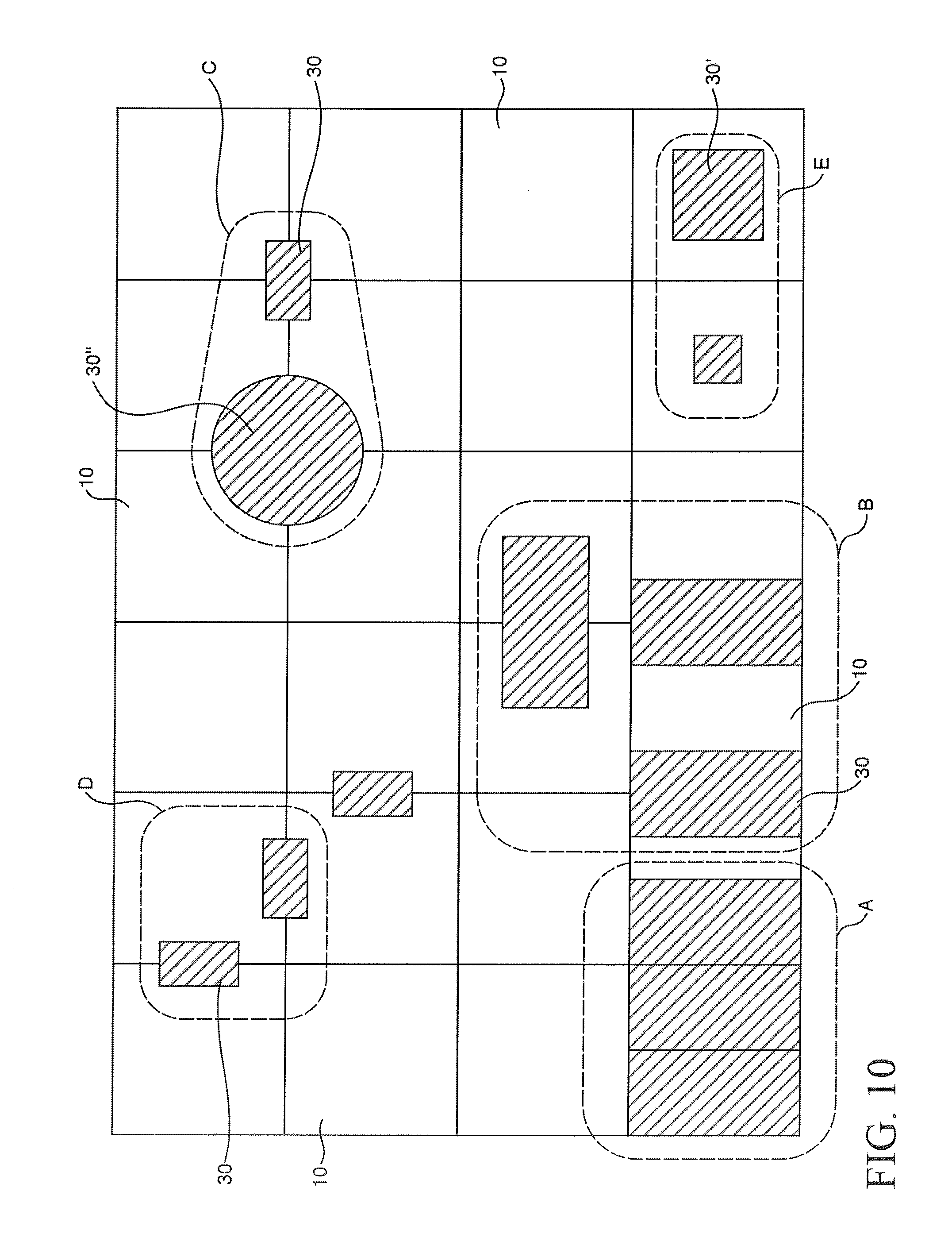
FIG. 10 is a schematic diagram of the elevated flooring system, showing various illustrative ways in which the blocks may connect to the flooring modules.
Like reference numerals refer to like parts throughout the several views of the drawings.
DETAILED DESCRIPTION
As shown in the accompanying drawings, the present invention is directed to an elevated flooring system 100 that can be used to create a modular flooring system along a surface such as the ground, and can also create various raised areas and elevated sections for increased height, such as for a dais, stage, podium, stairs or other structure. To accomplish this, the elevated flooring system 100 includes a plurality of floor modules 10, at least a portion of which collectively form at least one layer 11, and the layers 11 are separated by at least one block 30 supporting and interconnecting various floor modules 10 and layers 11 to create differences in height of various portions of the elevated flooring system 100.
As seen in FIGS. 1-3, the elevated flooring system 100 includes a plurality of floor modules 10. Each floor module 10 may be made of any suitable material for modular flooring, such as but not limited to natural and synthetic plastics, natural and synthetic resins, polymer-based materials such as polypropylene and polyethylene, and other similar materials and combinations thereof, which may also include stabilizers, fillers, plasticizers, colorants, or other additives to enhance physical, chemical and aesthetic characteristics. The floor modules 10 within an elevated flooring system 100 may all be made of the same material or different material from one another, and combinations thereof. Each floor module 10 may be formed by any suitable method according to the material used, such as but not limited to injection molding, compression molding, extrusion, die casting, carving or cutting such as by laser or other tool, and 3D printing. Each floor module 10 includes a first module surface 12, such as shown in FIG. 2. The first module surface 12 is a top surface configured to support pedestrian traffic, equipment, and additional components of the elevated flooring system 100. The first module surface 12 is smooth in that it contains no protrusions or obstructions to movement. In some embodiments, as shown in FIG. 1, some floor modules 10' may have a solid first module surface 12' that is a continuous surface without breaks or obstructions. In some embodiments, the first module surface 12' of certain floor modules 10 may include frictional members such as tread to provide traction and reduce slipping, but may not be so large as to obstruct movement. In other embodiments, as in FIGS. 1 and 2, some floor modules 10'' may have a first module surface 12'' including a plurality of holes 24 formed therein. Such holes 24 may pass through the first module surface 12'' to allow for drainage of fluids and materials therethrough, to prevent pooling of fluids that may cause unsafe conditions on the first module surface 12. The holes 24 may be any size and shape, not necessarily limited to a circular shape, and may be arranged in any pattern or configuration. In at least one embodiment, each hole 24 is configured to receive and retain an interfacing member 40, discussed in greater detail below. The holes 24 may be the same size, shape and configuration as one another, or may be different from one another. Similarly, different floor modules 10'' having holes 24 in their respective first module surfaces 12'' may have different numbers, patterns, arrangements, sizes, shapes and configurations of holes 24 from one to another.
Regardless of whether it is continuous or includes holes 24, the smooth first module surface 12 may also include a pattern, label, design or other indicia. The indicia may be unique and proprietary, or it may be generic. For instance, in some embodiments, the indicia may resemble wood grain patterns. In other embodiments, the indicia may be a pattern imitating tile, mosaics, laminate, glass, stone, marble or other building or flooring materials. In some embodiments, the indicia may be applied to the exterior of the first module surface 12 after the floor module 10 is formed, such as by heat application or pressing into the material before, during or after curing. In other embodiments, the indicia may be formed in the first module surface 12, such as through a process of in-mold labeling.
Each floor module 10 also includes second module surface 14 opposite the first module surface 12, shown in FIG. 3. The second module surface 14 therefore forms the underside of the floor module 10. The second module surface 14 is open to the surrounding environment, exposing a plurality of module ribs 26 formed in the floor module 10. The module ribs 26 support the first module surface 12 from underneath, providing structural support and rigidity to the floor module 10. The module ribs 26 may be made of the same material as the floor module 10 and may be formed during the formation of the floor module 10, however, in certain embodiments the module ribs 26 may be made of a different material from that of the flooring module 10. In a preferred embodiment, the module ribs 26 are of the same height as the floor module 10, spanning from the underside of the first module surface 12 to the bottom of the floor module 10 which may be placed on the ground, floor, or block(s) 30 as described in greater detail below. For instance, the floor modules 10 and module ribs 26 may have a height in the range of 5/8 inch to 6 inches. However, in other embodiments, at least some of the module ribs 26 have a height that is less than that of the floor module 10. The module ribs 26 may have any thickness suitable for the load capacity and material composition of the floor module 10 in order to support the same. For instance, in at least one embodiment the module ribs 26 have a thickness in the range of 1/16 inch to 1/2 inch. The various module ribs 26 within the same floor module 10 may have the same height and thickness, or may have different heights and thicknesses from one another. Similarly, the module ribs 26 of one floor module 10 may have the same or different heights and thicknesses from those of another floor module 10 within the elevated flooring system 100.
The module ribs 26 may extend along the perimeter of the floor module 10 and/or may also extend away from the perimeter toward the interior of the floor module 10, such as in the direction of the center of the floor module 10. The module ribs 26 may be linear, curved, curvilinear, or any shape or configuration, and may be positioned parallel to, intersecting, or at an angle to any of the other module ribs 26. Accordingly, various module ribs 26 may collectively define space(s) therebetween, such as module receiving spaces 28. Each module receiving space 28 is dimensioned, shaped and configured to receive a corresponding one of an extension 36 from a block 30 or the body 42 of an interfacing member 40, as described in greater detail below. In at least one embodiment, as shown in FIG. 3, the module ribs 26 may be linear and may collectively form and at least partially define square or rectangular receiving spaces 28 in the second module surface 14.
The second module surface 14 of the floor module 10 may also include at least one channel 22 formed therein. The channel(s) 22 spans at least a portion of the floor module 10, and in at least one embodiment spans the entire length or width of the floor module 10 along the second module surface 14. Multiple channels 22 may be included in the floor module 10, and may run parallel, perpendicular, or at an angle to other channels 22 in a common floor module 10. For instance, as shown in FIG. 3, channels 22 may run coaxially and perpendicular to one another. The channels 22 may extend through, be formed in and at least partially defined by the module ribs 26 on the second module surface 14 of the floor module 10. As depicted in FIG. 9, the module ribs 26' through which the channel(s) 22 extend may have a smaller height dimension than the remaining module ribs 26 of the floor module 10. The channel(s) 22 are dimensioned to receive cables, cords, wires, and other similar materials as may be beneficial to run through the floor module 10 rather than over it for safety reasons. Examples include, but are not limited to power cords, data cords and auxiliary cables and wires for equipment, gear, electronics, lights, audio-visual equipment such as speakers and microphones, and other devices that may be used in the vicinity of the elevated flooring system 100.
As shown in FIGS. 1-3, each floor module 10 is bounded by at least one perimetric side 16 that extends at least between the first module surface 12 and the second module surface 14. The sides 16 define the height of the floor module 10 in the vertical direction 52. There may be any number of sides 16, but in at least one embodiment the modules 10 include a first side 16a, second side 16b, third side 16c and fourth side 16d, such as shown in FIG. 3. The sides 16a, 16b, 16c and 16d may be arranged at right angles to the next adjacent side, such that the first and third sides 16a and 16c are opposite one another, and the second and fourth sides 16b and 16d are opposite one another. Accordingly, the floor module 10 may have a square or rectangular shape, although other shapes are also contemplated. For instance, in one embodiment the floor module 10 may be round and include a single side 16. In other embodiments the floor module 10 may be irregularly shaped and have any number of sides 16, which may be linear, curved, or curvilinear. The floor modules 10 may also have any dimension. For instance, the floor modules 10 may measure in the range of 6 inches to 14 feet in a first lateral direction 50 (width), 6 inches to 14 feet in a second lateral direction 54 (length), and 5/8 inch to 6 inches in the vertical direction 52 (height). In at least one embodiment the floor modules 10 may measure 12 inches.times.12 inches.times.1 inch. In other embodiments, the floor modules 10 may measure 18 inches.times.24 inches.times.1 inch. These are a few illustrative examples are not intended to be limiting.
Each side 16 may include an aperture 23 aligning with and providing access to a channel 22 of the second module surface 14. The aperture 23 may therefore be similarly sized and shaped as the channel 22, or may be larger or smaller than the corresponding channel 22 so long as access is still provided. In at least one embodiment, the aperture 23 is the same size, shape and configuration as a cross-section of the channel 22, such that the top of the aperture 23 has the same position and shape as the module ribs 26' forming the channel 22 on the second module surface 14, as depicted in FIG. 7. However, in other embodiments aperture 23 may have a different shape or size than the module ribs 26' corresponding to the channel 22.
Each side 16 may also include at least one connector 17, 18 dimensioned to engage a corresponding connector on a side 16 of an adjacent floor module 10 when joining floor modules 10 together. For instance, as depicted in FIGS. 2-4, at least one side 16 includes at least one first connector 17, and at least one different side 16 includes at least one second connector 18. Each first connector 17 extends from the edge of the side 16 away from the floor module 10, and may form a loop structure defining an opening 62 between the distal portion 63 of the first connector 17 and the side 16 of the floor module 10. This opening 62 may be dimensioned to receive and/or retain a portion of a second connector 18 therein, as described below. The first connector 17 may be configured in any suitable shape, such as curved, circular, semi-circular, oblong, linear, angular, triangular, square, rectangular, trapezoidal, and any combination thereof. In at least one embodiment, as depicted in FIG. 4, the first connector 17 may be shaped as a trapezoidal loop extending away from the side 16 of the floor module 10 and having a flat terminal edge. The first connector 17 may be at least a portion of the height of the floor module 10, such as less than half the height of the floor module 10. In other embodiments, the first connector 17 may span the entire height of the side 16, and therefore of the floor module 10.
At least one side 16 also includes at least one second connector 18. The second connector 18 also extends from the side 16 and away from the flooring module 10. Rather than forming a loop, the second connector 18 includes an extension 64 and a terminal portion 65 having a tab, lip or other similar feature. The extension 64 supports the terminal portion 65 at a predetermined distance from the side 16 of the floor module 10, and may itself be rounded or planar. The terminal portion 65 is correspondingly dimensioned to the opening 62 of the first connector 17 of another floor module 10, and may be planar, curved or have another type of shape. When joining adjacent floor modules 10 together, as depicted in FIG. 4, the terminal portion 65 of a second connector 18 is inserted into the opening 62 formed by a corresponding first connector 17 of an adjacent floor module 10. The opening 62 formed by the first connector 17 is dimensioned to receive the terminal portion 65 of the second connector 18. The first connector 17 may further be dimensioned to retain the terminal portion 65 of the second connector 18, such as by a frictional fit, snap fit, or other suitable connection. The terminal portion 65 of the second connector 18 may enter the opening 62 of the first connector 17 from either above or below the first connector 17 depending on the orientation of the terminal portion 65. The extension 64 of the second connector 18 may be dimensioned to receive the distal portion 63 of the first connector 17 when the two connectors 17, 18 are joined together. Accordingly, the first and second connectors 17, 18 are correspondingly dimensioned, and in some embodiments, may be matingly connected.
In at least one preferred embodiment, each side 16 may include multiple connectors of the same type. In other embodiments each side 16 may include multiple connectors of different types. For instance, one side 16 may include a plurality of first connectors 17, and a different side 16 may include a plurality of second connectors 18. In some embodiments, adjacent sides 16 may have the same type of connector 17, 18. For instance, in at least one embodiment as shown in FIG. 3, the first and second sides 16a, 16b each have at least one first connector 17, and the third and fourth sides 16c, 16d each have at least one second connector 18. In other embodiments, opposite sides 16 may have the same type of connector 18, such as the first and third sides 16a, 16c having first connector 17, and the second and fourth sides 16b, 16d having second connectors 18. In still other embodiments, each side 16 may include at least one first connector 17 and at least one second connector 18. Any number and combination of connectors 17, 18 may be present on any side 16 to achieve connection of adjacent floor modules 10.
Multiple floor modules 10 may be arranged adjacent to one another and connected to one another in a first lateral direction 50 through the first and second connectors 17, 18, as described above, to form a layer 11. A layer 11 may form a floor surface of the system 100 which can support people, animals, equipment, furniture, and other components of the floor system 100. A single layer 11 may include any number of floor modules 10 in the first lateral direction 50 or the second lateral direction 54, as shown in FIG. 1. Accordingly, each layer 11 is expandable in the lateral directions 50, 54. The boundaries of each layer 11 may be irregular, such that the layer 11 overall does not have to follow a uniform structure or shape. Further, a single layer 11 may include any combination of types of floor modules 10, 10', 10'', such that different areas of a layer 11 may have a solid surface while other areas may have holes for drainage purposes. The system 100 may include multiple layers 11 of floor modules 10, where each layer 11 is spaced apart in the vertical direction 52, as seen in FIG. 1. As used herein, the lateral directions 50, 54 are parallel to an underlying support surface, such as the ground or floor of a building or space, and may be substantially planar. The vertical direction 52 is perpendicular to the underlying support surface.
Referring to FIGS. 1, 5 and 6, the elevated flooring system 100 further includes at least one block 30 dimensioned to connect with at least one floor module 10, and may connect layers 11 of the system 100. Block(s) 30 may be made of the same material as the floor modules 10, such as but not limited to natural and synthetic plastics, natural and synthetic resins, polymer-based materials such as polypropylene and polyethylene, and other similar materials and combinations thereof, which may also include stabilizers, fillers, plasticizers, colorants, or other additives. Various blocks 30 used within the same elevated flooring system 100 may be made of the same material as each other, or of different materials from one another. Similarly, the blocks 30 may be the same color or different colors from one another, and may be the same or different colors from the floor modules 10. The block(s) 30 may be made by any suitable method according to the material used, such as but not limited to injection molding, compression molding, extrusion, die casting, carving or cutting such as by laser or other tool, and 3D printing.
Each block 30 includes a first block surface 31, which may be considered a top surface, and an opposite second block surface 34 which may be considered a bottom surface. The height of the block 30 defines the distance between the first and second block surfaces 32, 34. The first block surface 32 may preferably be solid, though in some embodiments it may include a bore(s) 33 extending through the block 30 from the first block surface 32 to the second block surface 34. The bore(s) 33 are sized, shaped and dimensioned to permit the passage of cables, wires, or other materials therethrough, which may be useful when running between layers 11 of the elevated flooring system 100. They may also be dimensioned to permit the passage of pins, rods or other similar rigid elongate material as may provide additional structural support to the elevated flooring system 100. The bore 33 may be of any shape, size and dimension, such as but not limited to circular, oval, square, rectangular, triangular, oblong, and irregular.
Each block 30 also includes at least one extension 36 protruding from the first block surface 32. Each extension 36 may be sized, shaped and configured to correspond with, and fit at least partially within, a module receiving space 28 of a floor module 10 as discussed above and shown in FIG. 7. Accordingly, the extensions 36 may be square, rectangular, circular, ovoid, spherical, irregular or other shaped, corresponding to the module receiving space 28 defined by the module ribs 26. In at least one embodiment, the extensions 36 are square in shape and correspond to square-shaped module receiving spaces 28 in a floor module 10. The extensions 36 may be the same or different shapes from one another on the same block 30, and may be the same or different shapes from extensions 36 of another block 30. The height of the extensions 36 may preferably correspond to the height of the module ribs 26 forming the boundaries of the corresponding module receiving space 28. In some embodiments, this may be the same height of the floor module 10. In other embodiments, the extensions 36 may be at least the same height or greater than that of the module ribs 26 forming the boundaries of the corresponding module receiving space 28. This may be useful in embodiments where the module ribs 26 forming the module receiving space 28 are less than the full height of the floor module 10. The extensions 36 may preferably be a fraction of the height of the remainder of the block 30, as in FIG. 5. In other embodiments, however, the extensions 36 may be the same height as, or greater than, the remainder of the block 30.
Further, each block 30 may include any number of extensions 36. For instance, a block 30 may include from one to twelve extensions 36, or more. In at least the embodiment shown in FIG. 5, the block 30 may include six extensions 36. In other embodiments, such as shown in FIG. 7, the block 30' may include two extensions 36. The various extensions 36 may be arranged or configured spaced apart from one another on the first block surface 32 by a predetermined distance, which may be uniform between the extensions 36. The extensions 36 may be arranged in a grid, as shown in FIG. 5, or may be arranged linearly as in FIG. 7. In still other embodiments, the extensions 36 may be arranged in any configuration with respect to one another. Accordingly, the size and dimensions of the block 30 may vary depending on the number and arrangement of extensions 36 included. In at least one embodiment as in FIGS. 5 and 7, the blocks 30, 30' may be rectangular or square in shape. In other embodiments, the block 30'' may be circular as in FIG. 10. In still other embodiments, the blocks 30 may be oblong or irregularly shaped. Further, the blocks 30 may be the same length and/or width as the floor modules 10. In other embodiments, the blocks 30 may have dimensions greater than or less than the length and/or width of the floor modules 10. In at least one embodiment, the blocks 30 have a greater height dimension than the floor modules 10, though in other embodiments the blocks 30 may be the same height as the floor modules 10 or smaller.
Each block 30 includes a second block surface 34 opposite the first block surface 32, such as shown in FIGS. 6 and 8. The second block surface 34 therefore forms the underside or bottom side of the block 30. In a preferred embodiment, the second block surface 34 is open, exposing a plurality of block ribs 38 formed in the block. The block ribs 38 support the first block surface 32 from underneath, providing structural support and rigidity to the block 30. The block ribs 38 may be made of the same material as the block 30 and may be formed during the formation of the block 30, however, in certain embodiments the block ribs 38 may be made of a different material from that of the block 30. In a preferred embodiment, the block ribs 38 have the same height as the block 30, spanning from the underside of the first block surface 32 to the bottom of the block 30 which may be placed on the ground, floor, or floor module(s) 10 as described in greater detail below. For instance, the blocks 30 and block ribs 38 may have a height in the range of 1/2 inch to 36 inches. However, in other embodiments, at least some of the block ribs 38 have a height that is less than that of the block 30. The block ribs 38 may have any thickness suitable for the load capacity and material composition of the block 30 in order to support the same. For instance, in at least one embodiment the block ribs 38 have a thickness in the range of 1/16 inch to 1/2 inch. The various block ribs 38 within the same block 30 may have a uniform height and thickness, or may have different heights and thicknesses from one another. Similarly, the block ribs 38 of one block 30 may have the same or different heights and thicknesses from those of another block 30 within the elevated flooring system 100.
The block ribs 38 may extend along the perimeter of the block 30 and may also extend away from the perimeter toward the interior of the block 30, such as in the direction of the center of the block 30. The block ribs 38 may be linear, curved, curvilinear, or any shape or configuration, and may be positioned parallel to, intersecting, or at an angle to any of the other block ribs 38. Accordingly, various block ribs 38 may collectively define space(s) therebetween, such as block receiving spaces 39. Each block receiving space 39 is dimensioned, shaped and configured to receive a corresponding body 42 of an interfacing member 40 or one of an extension 36 from another block 30, as described in greater detail below. The block receiving space 39 may further be dimensioned to retain the body 42 of an interfacing member 40 or one of an extension 36 from another block 30, such as by a frictional fit, snap fit, or other suitable connection. In at least one embodiment, as shown in FIG. 8, the block ribs 38 may be linear and may collectively form and at least partially define square or rectangular block receiving spaces 39 in the second block surface 34.
With reference now to FIGS. 8 and 9, the elevated flooring system 100 further includes at least one interfacing member 40 to facilitate the connection of a block(s) 30 with the first module surface 12 of a floor module 10. Each interfacing member 40 includes a body 42 and at least one leg 44 extending from the body 42. The interfacing members 40 may be made of the same material as the floor modules 10 or blocks 30, such as but not limited to natural and synthetic plastics, natural and synthetic resins, polymer-based materials such as polypropylene and polyethylene, and other similar materials and combinations thereof, which may also include stabilizers, fillers, plasticizers, colorants, or other additives. Various interfacing members 40 used within the same elevated flooring system 100 may be made of the same material as each other, or of different materials from one another. Similarly, the interfacing members 40 may be the same color or different colors from one another, and may be the same or different colors from the floor modules 10 and/or blocks 30. The interfacing members 40 may be made by any suitable method according to the material used, such as but not limited to injection molding, compression molding, extrusion, die casting, carving or cutting such as by laser or other tool, and 3D printing. Preferably, the body 42 and leg(s) 44 of a single interfacing member 40 may be made of the same material, and may be of a unitary construction. In other embodiments, however, the legs 44 may be added to the body 42, such as by adhesive, molding, co-extrusion, frictional connection such as screw action, or the like.
The body 42 is sized, shaped and dimensioned to correspond to, and fit at least partially within, a block receiving space 39 accessed through the second block surface 34, as shown in FIG. 8. In at least one embodiment, the body 42 may be square or rectangular in shape, although in other embodiments the body 42 may be circular, spherical, ovoid, oblong, angular, or irregularly shaped, as but a few non-limiting examples. Accordingly, a block 30 may be stacked on top of at least one interfacing member 40. The height of the body 42 may therefore be at least the height of the block receiving space 39, and may be the height of the block 30. In certain embodiments, the body 42 of an interfacing member 40 may also be dimensioned to correspond to, and fit at least partially within, a module receiving space 28 of a floor module 10. The body 42 may be solid, or in some embodiments may define a cavity therein.
The legs 44 of the interfacing member 40 may have any shape and dimension, and the legs 44 of a common interfacing member 40 may have a uniform shape and dimension as one another. For instance, in at least one embodiment the legs 44 may be pegs, pins, or other type projections that extend from the body 42 of the interfacing member 40, and may be cylindrical or rectangular. In at least one embodiment as shown in FIG. 9, the legs 44 may be cylindrical and dimensioned to fit within corresponding ones of holes 24 on the first module surface 12 of a floor module 10''. Indeed, the pattern of holes 24 on the first module surface 12 of a floor module 10'' may be designed to allow for any number of configurations of interfacing members 40 to be selectively attached thereto as a result of a frictional fit between legs 44 within the holes 24. In other embodiments, the legs 44 of interfacing members 40 and the holes 24 of a floor module 10'' may be matingly fit, such as with tongue and groove features.
The elevated flooring system 100 is fully modular and so can be assembled in any number of ways, with the various components being selectively attachable to other components. For instance, as shown in FIG. 9, a floor module 10 may act as the base to which a plurality of interfacing members 40 may be attached, such as by insertion of the legs 44 into the holes 24 of the floor module 10''. The bodies 42 of the interfacing members 40 then extend above the first module surface 12 and can be inserted to the block receiving spaces 39 of a block 30. Accordingly, interfacing members 40 may be placed on top of floor modules 10, and blocks 30 may be placed on top of (and surrounding) the interfacing members 40. Blocks 30 may also be stacked on other blocks 30 to achieve greater elevation. Similarly, floor modules 10 may be further placed on top of blocks 30, such as by the extensions 36 of the block 30 being received within module receiving spaces 28 of the floor module 10, as in FIG. 7. In such a manner, the elevated flooring system 100 may be assembled with any number of floor modules 10 and any number of blocks 30 to cover any amount of space along first and second lateral directions 50, 54 and reach any height in the vertical direction 50, as shown in FIG. 1. Further, any number of blocks 30 may be stacked on the interfacing members 40 or other blocks 30 to create any amount of distance between layers 11 of the elevated flooring system 100. It should also be appreciated that either blocks 30 or floor modules 10 may be placed on the ground, floor, or other underlying structure on which the elevated flooring system 100 is to be assembled to form the base of the elevated flooring system 100.
Further, although layers 11 are formed by joining adjacent floor modules 10 through the first and second connectors 17, 18, the floor modules 10 may further be locked in place by the placement of blocks 30 above or below. A block 30 may be placed aligning at least a portion of the joining floor module 10, or it may be placed to overlap the joining floor module(s) 10. FIG. 10 demonstrates various exemplary placement positions of blocks 30 relative to floor modules 10. For instance, a block 30 may fully align with a corresponding floor module 10 as in group A. A block 30 may also be positioned to overlap two adjacent floor modules 10, as in group B. Blocks 30 may also be placed at the vertices where multiple floor modules 10 come together, as in group C. Blocks 30 may overlap adjacent floor modules 10 along at least a portion of a shared side 16, as in group D. Finally, a floor module 10 may be only partially supported by a block 30, as in group E. These are but a few illustrative examples and are not intended to be limiting.
Since many modifications, variations and changes in detail can be made to the described preferred embodiments, it is intended that all matters in the foregoing description and shown in the accompanying drawings be interpreted as illustrative and not in a limiting sense. Thus, the scope of the invention should be determined by the appended claims and their legal equivalents. Now that the invention has been described.
* * * * *
References
D00000
D00001
D00002
D00003
D00004
D00005
D00006
D00007
D00008
XML
uspto.report is an independent third-party trademark research tool that is not affiliated, endorsed, or sponsored by the United States Patent and Trademark Office (USPTO) or any other governmental organization. The information provided by uspto.report is based on publicly available data at the time of writing and is intended for informational purposes only.
While we strive to provide accurate and up-to-date information, we do not guarantee the accuracy, completeness, reliability, or suitability of the information displayed on this site. The use of this site is at your own risk. Any reliance you place on such information is therefore strictly at your own risk.
All official trademark data, including owner information, should be verified by visiting the official USPTO website at www.uspto.gov. This site is not intended to replace professional legal advice and should not be used as a substitute for consulting with a legal professional who is knowledgeable about trademark law.