Reinforcement structure
Richardson , et al. Fe
U.S. patent number 10,196,097 [Application Number 15/656,804] was granted by the patent office on 2019-02-05 for reinforcement structure. This patent grant is currently assigned to Zephyros, Inc.. The grantee listed for this patent is Zephyros, Inc.. Invention is credited to Alexander G. Mangiapane, Henry E. Richardson.


| United States Patent | 10,196,097 |
| Richardson , et al. | February 5, 2019 |
Reinforcement structure
Abstract
A structural reinforcement comprising a base reinforcing structure including a plurality of ribs and having a first surface and a second surface, an expandable adhesive material located onto a first portion of the first surface, and a sealant material located around an edge of the second surface, the second surface being substantially free of any of the plurality of ribs.
| Inventors: | Richardson; Henry E. (Washington, MI), Mangiapane; Alexander G. (Macomb Township, MI) | ||||||||||
|---|---|---|---|---|---|---|---|---|---|---|---|
| Applicant: |
|
||||||||||
| Assignee: | Zephyros, Inc. (Romeo,
MI) |
||||||||||
| Family ID: | 59593157 | ||||||||||
| Appl. No.: | 15/656,804 | ||||||||||
| Filed: | July 21, 2017 |
Prior Publication Data
| Document Identifier | Publication Date | |
|---|---|---|
| US 20180022397 A1 | Jan 25, 2018 | |
Related U.S. Patent Documents
| Application Number | Filing Date | Patent Number | Issue Date | ||
|---|---|---|---|---|---|
| 62365140 | Jul 21, 2016 | ||||
| Current U.S. Class: | 1/1 |
| Current CPC Class: | B62D 21/15 (20130101); C09J 201/00 (20130101); B62D 29/041 (20130101); B62D 29/002 (20130101); B62D 25/00 (20130101); B29C 69/02 (20130101); B29K 2105/04 (20130101); B29K 2063/00 (20130101); B29L 2031/30 (20130101); B29K 2105/0097 (20130101) |
| Current International Class: | B60J 7/00 (20060101); B29C 69/02 (20060101); B62D 29/04 (20060101); B62D 21/15 (20060101); B62D 29/00 (20060101); B62D 25/00 (20060101); C09J 201/00 (20060101) |
| Field of Search: | ;296/187.03 |
References Cited [Referenced By]
U.S. Patent Documents
| 3984497 | October 1976 | Owens et al. |
| 3985703 | October 1976 | Ferry et al. |
| 4034013 | July 1977 | Lane |
| 4096202 | June 1978 | Farnham et al. |
| 4304709 | December 1981 | Salee |
| 4306040 | December 1981 | Baer |
| 4495324 | January 1985 | Chacko et al. |
| 4536436 | August 1985 | Maeoka et al. |
| 5102188 | April 1992 | Yamane |
| 5275853 | January 1994 | Silvis et al. |
| 5464924 | November 1995 | Silvis et al. |
| 5575526 | November 1996 | Wycech |
| 5755486 | May 1998 | Wycech |
| 5766719 | June 1998 | Rimkus |
| 5884960 | March 1999 | Wycech |
| 5932680 | August 1999 | Heider |
| 5962093 | October 1999 | White et al. |
| 6058673 | May 2000 | Wycech |
| 6103784 | August 2000 | Hilborn et al. |
| 6131897 | October 2000 | Barz et al. |
| 6272809 | August 2001 | Wycech |
| 6348513 | February 2002 | Hilborn et al. |
| 6368438 | April 2002 | Chang et al. |
| 6378933 | April 2002 | Schoen |
| 6467834 | October 2002 | Barz |
| 6478367 | November 2002 | Ishikawa |
| 6607238 | August 2003 | Barz |
| 6620501 | September 2003 | Kassa et al. |
| 6793274 | September 2004 | Riley |
| 6811864 | November 2004 | Czaplicki et al. |
| 6846559 | January 2005 | Czaplicki et al. |
| 6883858 | April 2005 | Barz |
| 6890021 | May 2005 | Bock |
| 6896320 | May 2005 | Kropfeld |
| 6920693 | July 2005 | Hankins et al. |
| 6921130 | July 2005 | Barz |
| 6932421 | August 2005 | Barz |
| 6935681 | August 2005 | Hasler et al. |
| 6941719 | September 2005 | Busseuil et al. |
| 6953219 | October 2005 | Lutz et al. |
| 7004536 | February 2006 | Wieber |
| 7043815 | May 2006 | Lande et al. |
| 7077460 | July 2006 | Czaplicki |
| 7111899 | September 2006 | Gray |
| 7125461 | October 2006 | Czaplicki |
| 7199165 | April 2007 | Kassa et al. |
| 7249415 | July 2007 | Larsen et al. |
| 7313865 | January 2008 | Czaplicki et al. |
| 7374219 | May 2008 | Brennecke |
| 7478478 | January 2009 | Lutz et al. |
| 7503620 | March 2009 | Brennecke et al. |
| 7641264 | January 2010 | Niezur |
| 7673930 | March 2010 | Stratman |
| 7748773 | July 2010 | Niezur |
| 7926867 | April 2011 | Kochert |
| 8002332 | August 2011 | Coon et al. |
| 8020924 | September 2011 | Niezur et al. |
| 8047603 | November 2011 | Goral |
| 8361589 | January 2013 | Kraushaar |
| 8366181 | February 2013 | Belpaire |
| 8388037 | March 2013 | LaNore et al. |
| 9034135 | May 2015 | Schulenburg et al. |
| 9096005 | August 2015 | Kanie |
| 9592858 | March 2017 | Kraushaar |
| 9782950 | October 2017 | Richardson |
| 9895712 | February 2018 | Buck |
| 2001/0042353 | November 2001 | Honda |
| 2002/0125739 | September 2002 | Czaplicki |
| 2003/0137162 | July 2003 | Kropfeld |
| 2004/0076831 | April 2004 | Hable et al. |
| 2004/0130185 | July 2004 | Hasler |
| 2004/0204551 | October 2004 | Czaplicki et al. |
| 2004/0256888 | December 2004 | Le Gall |
| 2004/0262853 | December 2004 | Larsen et al. |
| 2005/0035628 | February 2005 | Behr |
| 2005/0159531 | July 2005 | Ferng et al. |
| 2005/0212332 | September 2005 | Sheldon et al. |
| 2005/0230027 | October 2005 | Kassa |
| 2005/0268454 | December 2005 | White |
| 2005/0269840 | December 2005 | Finerman et al. |
| 2006/0008615 | January 2006 | Muteau |
| 2006/0181089 | August 2006 | Andre |
| 2007/0018483 | January 2007 | Kerscher |
| 2007/0080559 | April 2007 | Stolarski |
| 2007/0090666 | April 2007 | Brennecke |
| 2007/0095475 | May 2007 | Hable et al. |
| 2007/0096508 | May 2007 | Rocheblave |
| 2008/0029200 | February 2008 | Sheasley |
| 2009/0085379 | April 2009 | Takahashi |
| 2010/0015427 | January 2010 | Belpaire et al. |
| 2010/0092733 | April 2010 | Blank et al. |
| 2010/0117397 | May 2010 | Richardson |
| 2010/0253004 | October 2010 | Lehmann et al. |
| 2011/0049323 | March 2011 | Belpaire et al. |
| 2011/0104413 | May 2011 | Mendibourne |
| 2011/0189428 | August 2011 | Belpaire et al. |
| 2011/0206890 | August 2011 | Belpaire |
| 2011/0236610 | September 2011 | Belpaire |
| 2011/0236616 | September 2011 | Belpaire |
| 2012/0141724 | June 2012 | Belpaire et al. |
| 2012/0207986 | August 2012 | Belpaire et al. |
| 2013/0133771 | May 2013 | Richardson |
| 2013/0181470 | July 2013 | LaNore et al. |
| 2013/0220418 | August 2013 | Heidtman et al. |
| 2014/0091584 | April 2014 | McConnell |
| 2015/0016737 | January 2015 | Yie et al. |
| 2015/0165737 | June 2015 | Richardson |
| 2016/0273160 | September 2016 | Braymand |
| 2017/0072887 | March 2017 | Richardson |
| 2018/0029328 | February 2018 | Richardson |
| 2018/0029644 | February 2018 | Li et al. |
| 2018/0037264 | February 2018 | Li et al. |
| 2018/0037703 | February 2018 | Richardson |
| 19812288 | May 1999 | DE | |||
| 19856255 | Jan 2000 | DE | |||
| 19838955 | Mar 2000 | DE | |||
| 19858903 | Jun 2000 | DE | |||
| 1122153 | Oct 2003 | EP | |||
| 1391250 | Feb 2004 | EP | |||
| 1759959 | Mar 2007 | EP | |||
| 1759964 | Mar 2007 | EP | |||
| 1932648 | Jun 2008 | EP | |||
| 1373053 | Dec 2008 | EP | |||
| 2019027 | Jan 2009 | EP | |||
| 2117909 | Nov 2009 | EP | |||
| 2121270 | Nov 2009 | EP | |||
| 2147848 | Jan 2010 | EP | |||
| 2154052 | Feb 2010 | EP | |||
| 2159109 | Mar 2010 | EP | |||
| 2159136 | Mar 2010 | EP | |||
| 2165919 | Mar 2010 | EP | |||
| 2183150 | May 2010 | EP | |||
| 2238012 | Oct 2010 | EP | |||
| 2323891 | May 2011 | EP | |||
| 2331368 | Jun 2011 | EP | |||
| 2334540 | Jun 2011 | EP | |||
| 2337728 | Jun 2011 | EP | |||
| 2463180 | Jun 2012 | EP | |||
| 2234803 | Oct 2012 | EP | |||
| 2289769 | Nov 2012 | EP | |||
| 2289771 | Jan 2013 | EP | |||
| 2553036 | Feb 2013 | EP | |||
| 2401191 | Apr 2013 | EP | |||
| 2749263 | May 1996 | FR | |||
| 2421478 | Jun 2006 | GB | |||
| 07-031569 | Feb 1995 | JP | |||
| 07-117728 | May 1995 | JP | |||
| 2002-362412 | Dec 2002 | JP | |||
| 2003-063443 | Mar 2003 | JP | |||
| 2000/037302 | Jun 2000 | WO | |||
| 2002/074609 | Sep 2002 | WO | |||
| 2005/105405 | Nov 2005 | WO | |||
| 2009/080814 | Jul 2009 | WO | |||
| 2010/018190 | Feb 2010 | WO | |||
Other References
|
Potentially Related U.S. Appl. No. 15/656,501, filed Jul. 21, 2017, published as US 2018/0029644 on Feb. 1, 2018. cited by applicant . Potentially Related U.S. Appl. No. 15/785,878, filed Oct. 17, 2017, published as US 2018/0037264 on Feb. 8, 2018. cited by applicant . International Search Report and Written Opinion for Application No. PCT/US2017/043332 dated Nov. 2, 2017. cited by applicant . International Search Report and Written Opinion for Application No. PCT/US2017/043252 dated Nov. 10, 2017. cited by applicant. |
Primary Examiner: Patel; Kiran B
Attorney, Agent or Firm: The Dobrusin Law Firm, PC
Claims
What is claimed is:
1. A structural reinforcement comprising: i) a base reinforcing structure including a plurality of ribs and having a first portion and a second portion, the first and second portions substantially perpendicular relative to each other; ii) the first portion including a first side and a second side opposing the first side, each of the first side and second side including the plurality of ribs; iii) an expandable adhesive material located onto at least a portion of the first side and second side of the first portion and not located on the second portion; iv) a sealant material located around an edge of the second portion and not in direct contact with the expandable adhesive material, and the second portion not including any of the plurality of ribs.
2. The structural reinforcement of claim 1, wherein the second portion includes a substantially flat portion.
3. The structural reinforcement of claim 1, wherein the first portion is free of any sealant material.
4. The structural reinforcement of claim 2, wherein the sealant material is located adjacent an edge of the second portion and adjacent to the first portion.
5. The structural reinforcement of claim 1, wherein the structural adhesive material has a higher expansion rate than the sealant material.
6. The structural reinforcement of claim 1, wherein the sealant material has a higher expansion rate than the structural adhesive material.
7. The structural reinforcement of claim 4, wherein the base reinforcing structure includes a polymeric material.
8. The structural reinforcement of claim 4, wherein the base reinforcing structure includes a nylon material.
9. The structural reinforcement of claim 8, wherein the nylon material is glass fiber reinforced.
10. The structural reinforcement of claim 1, wherein the base reinforcing structure includes a fiber reinforced thermoplastic epoxy material.
Description
FIELD OF THE INVENTION
The present invention relates generally to reinforcement of structures, and more particularly to reinforcement of vehicle structures using structural reinforcements with associated adhesives and sealants.
BACKGROUND OF THE INVENTION
In various locations throughout transportation vehicles, recent years have seen the increased use of structural reinforcements in which vehicle cavities are commonly fitted with structural reinforcements that aid in controlling deformation from an impact. For some applications, it has become popular in recent years to employ a carrier structure in combination with a secondary material, such as an expandable adhesive material as part of the reinforcement. See e.g., U.S. Pat. Nos. 6,932,421; 6,921,130; 6,920,693; 6,890,021; and 6,467,834 all incorporated by reference. Often, these structures are manufactured using injection molding and/or co-extrusion processes.
However, the remains a need for structural reinforcements that include multiple differing secondary materials and/or attachments while still maintaining minimal cycle time during manufacturing.
SUMMARY OF THE INVENTION
The present teachings meet one or more of the above needs by the improved devices and methods described herein.
In one aspect, the present teachings pertain to a structural reinforcement comprising a base reinforcing structure including a plurality of ribs and having a first portion and a second portion, an expandable adhesive material located onto at least a portion of a first side and a second side of the first portion, and a sealant material located around an edge of the second portion, the second portion being substantially free of any of the plurality of ribs.
The expandable adhesive material and sealant material may be free of any direct contact with one another in the green state. The expandable adhesive material and sealant material may be free of any direct contact with one another post-activation. The expandable adhesive material and sealant material may make direct contact with one another during activation. The second portion may include a substantially flat portion. The first portion may be substantially free of any sealant material. The second portion may be substantially free of any structural adhesive material. The first portion may be arranged such that it is in a plane that lies substantially perpendicular to the plane of the second portion. The sealant material may be located along an edge of the second portion that is arranged adjacent to the first portion. The structural adhesive material have a higher expansion rate during activation than the sealant material. The sealant material have a higher expansion rate during activation than the structural adhesive material.
The teachings herein further provide for a method comprising locating a polymeric material in a mold to form a base reinforcing structure including a first portion and a second portion, molding an expandable adhesive material onto the base reinforcing structure, removing the base reinforcing structure and adhesive material from the mold, and extruding a sealant material onto an edge of the base reinforcing structure, wherein the sealant material is located onto the second portion of the base reinforcing structure that is substantially free of any adhesive material.
The sealant material may be extruded via a mini-applicator. The expandable adhesive material and sealant material may be applied so that they are substantially free of any direct contact with one another in the green state. The expandable adhesive material and sealant material may be applied so that they are free of any direct contact with one another post-activation. The expandable adhesive material and sealant material may be applied so that they make direct contact with one another during activation. The second portion may be molded to include a substantially flat portion. No sealant material may be applied to the first portion. No structural adhesive material may be molded onto the second portion. The first portion may be molded such that it is in a plane that lies substantially perpendicular to the plane of the second portion. The sealant material may be extruded along an edge of the second portion that is arranged adjacent to the first portion.
DESCRIPTION OF THE DRAWINGS
FIG. 1 is a perspective view of an illustrative reinforcement in accordance with the present teachings.
FIG. 2 is a perspective view of the reinforcement of FIG. 1.
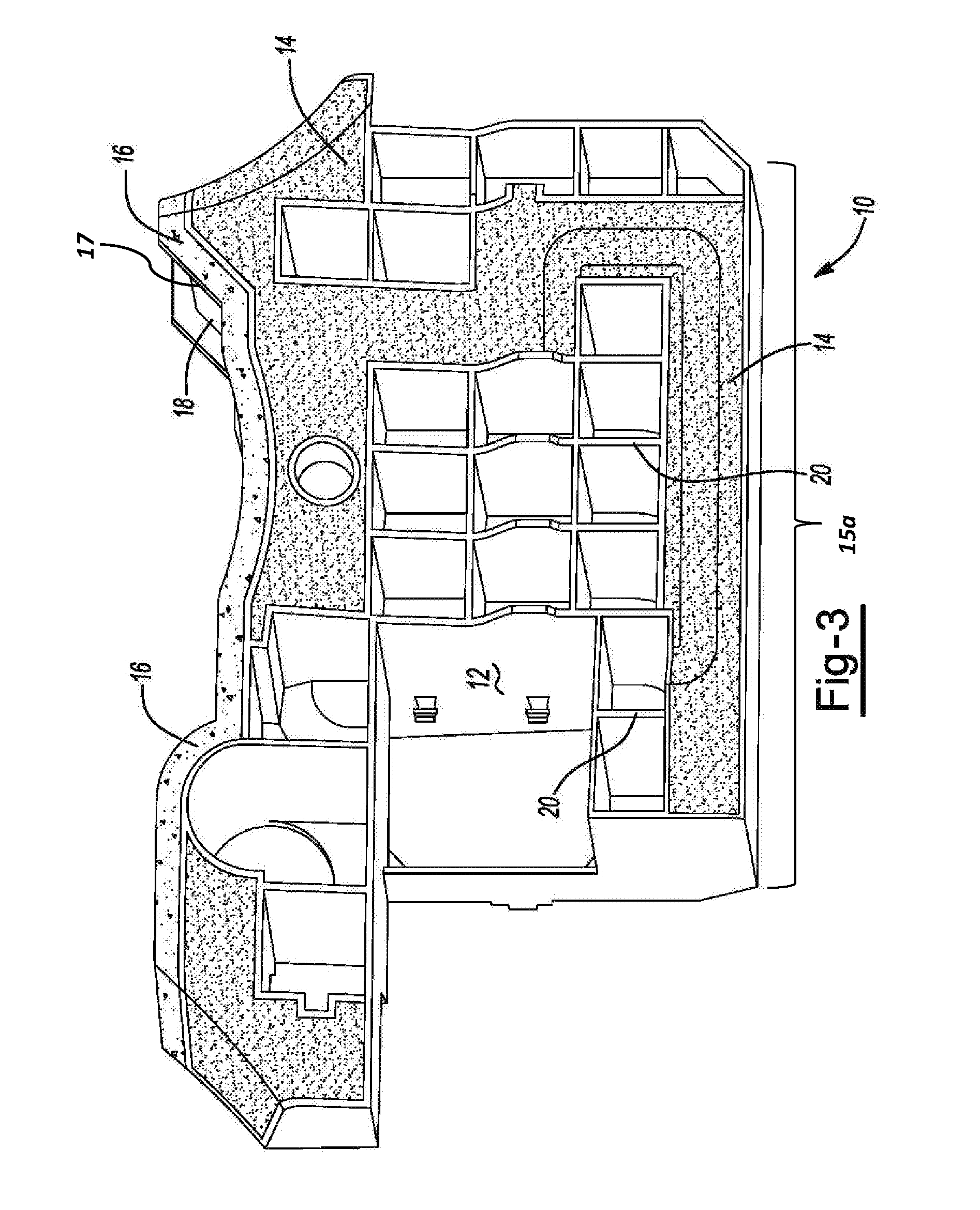
FIG. 3 is a perspective view of the reinforcement of FIG. 1.
DETAILED DESCRIPTION
The explanations and illustrations presented herein are intended to acquaint others skilled in the art with the invention, its principles, and its practical application. The specific embodiments of the present invention as set forth are not intended as being exhaustive or limiting of the invention. The scope of the invention should be determined with reference to the appended claims, along with the full scope of equivalents to which such claims are entitled. The disclosures of all articles and references, including patent applications and publications, are incorporated by reference for all purposes. Other combinations are also possible as will be gleaned from the following claims, which are also hereby incorporated by reference into this written description.
This application claims the benefit of the priority date U.S. Provisional Application Ser. No. 62/365,140, filed Jul. 21, 2016, the contents of that application being hereby incorporated by reference herein for all purposes.
The invention herein contemplates a unique approach for providing a structural reinforcement that carries at least two different secondary materials.
The base reinforcing structure may be formed of a moldable material, which may be a polymeric material, which may be a nylon material. The base reinforcing material may be formed by pultrusion. The polymeric material may be a reinforced polymeric material. For example, the polymeric material may be a glass fiber reinforced nylon. The polymeric material may be a polyurethane. The polymeric material may be a thermoset material. The polymeric material may be a thermoplastic material. The polymeric material may be a thermoplastic epoxy material. The polymeric material may be a fiber reinforced thermoplastic epoxy material.
The adhesive material and/or sealant material may be a material that experiences expansion and/or cure upon exposures to temperatures of between about 148.89.degree. C. to about 204.44.degree. C. (about 300.degree. F. to about 400.degree. F.) (i.e., temperatures typically experienced in automotive painting or coating operations). The adhesive material and/or material may be foamed to a volume of at least 5% greater, at least 50% greater, at least 200% greater, at least 1000% greater, at least 2000% greater, at least 5000% greater or higher relative to the original unexpanded volume.
The adhesive and/or sealant material may be an epoxy based material such as those disclosed in U.S. Pat. Nos. 5,884,960; 6,348,513; 6,368,438; 6,811,864; 7,125,461; 7,249,415; and U.S. Patent Publication No. 2004/0076831, hereby incorporated by reference.
The adhesive materials and sealant materials may include an epoxy resin component. Epoxy resin is used herein to mean any of the conventional epoxy materials containing at least one epoxy functional group. The epoxy resins can be difunctional, trifunctional, multifunctional, combinations thereof or otherwise. Moreover, the term epoxy resin can be used to denote one epoxy resin or a combination of epoxy resins. The polymer-based materials may be epoxy-containing materials having one or more oxirane rings polymerizable by a ring opening reaction. In preferred embodiments, the adhesive and/or sealant material of this invention includes between about 2% and 70% by weight epoxy resin, more preferably between about 7% and 50% by weight epoxy resin and even more preferably between about 15% and 40% by weight epoxy resin and even possibly between about 15% and about 25% by weight epoxy resin.
The epoxy may be aliphatic, cycloaliphatic, or aromatic. The epoxy may be supplied as a solid (e.g., as pellets, chunks, pieces or the like) or a liquid (e.g., an epoxy resin) or both. As used herein, a resin is considered to be a solid resin if it is solid at a temperature of 23.degree. C. and is considered to be a liquid resin if it a liquid at 23.degree. C. The presence of the epoxy resin increases the adhesion, flow properties, or both of the adhesive and/or sealant. One exemplary epoxy resin may be a phenolic resin, which may be a novalac type or other type resin. For example, bisphenol A resin, bisphenol F resin, a combination thereof or the like may be employed. Moreover, various mixtures of several different epoxy resins may be employed. Examples of suitable epoxy resins are sold under the tradename DER.RTM. (e.g., DER 331, DER 661, DER 662), commercially available from the Dow Chemical Company, Midland, Mich.
Liquid epoxy resins may be utilized. Such resins may be utilized to reduce the overall viscosity of the adhesive or sealant. Liquid epoxy resins that may be used typically have a viscosity at a temperature of 23.degree. C. of at least 5000, more typically at least 8000 and even possibly at least 11,000 cps, but typically less than 30,000, more typically less than 22,000 and even possibly less than 15,000 cps, although higher and lower values may also be possible unless otherwise stated. The liquid epoxy resin typically has an epoxy equivalent weight of at least 80, more typically at least 150 and even possibly at least 185 g/eq, but typically less than 300, more typically less than 220 and even possibly less than 195 g/eq, although higher and lower values may also be possible unless otherwise stated. Preferred liquid resins include diglycidyl ethers that may be aromatic phenol based (bisphenol A or F) and are sold under the tradename DER 331, commercially available from the Dow Chemical Company and EPON 828 and EPON 863, commercially available from Hexion Specialty Chemicals.
In the preferred embodiment the epoxy resins used are such that the formulated adhesive and sealant are dry to the touch at ambient temperature.
Additional polymeric materials may be utilized. As one example, one or more thermoplastic modifiers such as polyethers which include pendant hydroxyl moieties. Particularly desirable thermoplastic polyethers are phenoxy resins. As used herein, phenoxy resin is a polyhydroxyether, with ether linkages along the polymer backbone and pendant hydroxyl groups. One useful phenoxy resin is the reaction product of a phenol based difunctional epoxy resin and a difunctional phenol (for example the reaction product of bisphenol A epoxy with bisphenol A). A similar material may also be synthesized directly from a bisphenol (for example bisphenol A) and epichlorohydrin. The terminal epoxy group may be ring opened to generate a terminal alpha glycol group. The phenoxy resins have weight-average molecular weights of at least about 5,000, more typically at least about 25,000 and still more typically at least about 50,000 but less than about 100,000, more typically less than about 75,000 and still more typically less than about 60,000. Other thermoplastic polyethers include aromatic ether/amine repeating units in their backbones such as polyetheramines, poly(amino ethers), copolymers of monoethanolamine and diglycidyl ether, combinations thereof or the like. Examples of thermoplastic polyethers are disclosed in U.S. Pat. Nos. 5,275,853; 5,464,924 and 5,962,093. The thermoplastic modifiers such as the polyethers preferably comprise between 3% and about 40% by weight of the adhesive or sealant material and even more preferably between about 10% and 30% more preferably between 10% and about 15%.
Several additional polymers may be incorporated into the adhesive and/or sealant material, e.g., by copolymerization, by blending, or otherwise. For example, without limitation, other polymers that might be appropriately incorporated into the sealant material include halogenated polymers, polycarbonates, polyketones, urethanes, polyesters, silanes, sulfones, allyls, olefins, styrenes, acetates, ethylene vinyl acetates, acrylates, methacrylates, epoxies, silicones, phenolics, rubbers, polyphenylene oxides, terphthalates, or mixtures thereof. Other potential polymeric materials may be or may include, without limitation, polyethylene, polypropylene, polystyrene, polyolefin, polyacrylate, poly(ethylene oxide), poly(ethyleneimine), polyester, polyurethane, polysiloxane, polyether, polyphosphazine, polyamide, polyimide, polyisobutylene, polyacrylonitrile, poly(vinyl chloride), poly(methylmethacrylate), poly(vinyl acetate), poly(vinylidene chloride), polytetrafluoroethylene, polyisoprene, polyacrylamide, polyacrylic acid, polymethacrylate, and polyacetals.
It is possible that the adhesive and/or sealant material includes an acrylate copolymer, acetate copolymer or both. The adhesive and/or sealant material may include ethylene methyl acrylate (EMA), ethylene vinyl acetate (EVA) or a combination thereof. When included, EMA is typically between about 1% and about 70%, more typically between about 30% and about 60% and even more typically between about 44% and about 55% by weight of the adhesive and/or sealant material. A desirable EMA can have a melt index between about 110 and about 150 grams/10 min. (e.g., about 135 grams/10 min.). One preferred EMA is sold under the tradename TC140 and is commercially available from Exxon. When included, EVA is typically between about 1% and about 70%, more typically between about 2% and about 10% and even more typically between about 3% and about 5% by weight of the melt flow material.
It is also contemplated that the adhesive and/or sealant material can include one or more isocyanate reactive ingredients (e.g., polyols), which can be reactive with blocked isocyanates. Example of such ingredients and isocyanates are disclosed in U.S. Patent Application, Publication No. 2005/0320027, which is incorporated herein by reference for all purposes.
The adhesive and/or sealant material may include one or more additional polymers (e.g., copolymers), which are typically, but not necessarily copolymers or terpolymers, which can include a variety of different polymers, such as thermoplastics, elastomers, thermosets, thermosettables combinations thereof or the like. For example, and without limitation, polymers that might be appropriately incorporated into the adhesive and/or sealant material include halogenated polymers, polycarbonates, polyketones, and polymers of urethanes, polyesters, silanes, sulfones, allyls, olefins, styrenes, acrylates, methacrylates, epoxies, silicones, phenolics, rubbers, polyphenylene oxides, terphthalates, acetates (e.g., EVA), acrylates, methacrylates (e.g., ethylene methyl acrylate polymer) or mixtures thereof. Other potential polymeric materials may be or may include, without limitation, polyolefin (e.g., polyethylene, polypropylene) polystyrene, polyacrylate, polyethylene oxide), poly(ethyleneimine), polyester, polyurethane, polysiloxane, polyether, polyphosphazine, polyimide, polyimide, polyisobutylene, polyacrylonitrile, polyvinyl chloride), poly(methyl methacrylate), polyvinyl acetate), poly(vinylidene chloride), polytetrafluoroethylene, polyisoprene, polyacrylamide, polyacrylic acid, polymethacrylate. Although not required, it may be desired for the adhesive and/or sealant material to include one or more ethylene polymers or copolymers such as ethylene acrylates, ethylene acetates, or the like. Ethylene methacrylate and ethylene vinyl acetate are two preferred ethylene copolymers. When used, the one or more additional polymers comprises about 0.1% to about 50%, more preferably about 1% to about 20% and even more preferably about 5% to about 15% by weight of the adhesive and/or sealant material.
The adhesive and/or sealant material can also include one or more materials for controlling the rheological characteristics of the sealant material over a range of temperatures (e.g., up to about 250.degree. C. or greater). Any suitable art-disclosed rheology modifier may be used, and thus the rheology modifier may be organic or inorganic, liquid or solid, or otherwise. The rheology modifier may be a polymer, and more preferably one based upon an olefinic (e.g., an ethylene, a butylenes, a propylene or the like), a styrenic (e.g., a styrene-butadiene-containing rubber), an acrylic or an unsaturated carboxylic acid or its ester (such as acrylates, methacrylates or mixtures thereof; e.g., ethylene methyl acrylate (EMA) polymer) or acetates (e.g., EVA). The rheology modifier may be provided in a generally homogeneous state or suitable compounded with other ingredients. It is also contemplated that the various clays, minerals or other materials discussed in relation to fillers below can be employed to modify rheology of the adhesive and/or sealant material.
The adhesive and/or sealant material may each include one or more curing agents that assist the adhesive and/or sealant material in curing by crosslinking of the polymers, epoxy resins and other ingredients in the material. The amount of curing agents or curing agent accelerators present in the adhesive and/or sealant material range from about 0.001% by weight to about 9% by weight and more typically from about 0.2 to about 6 wt %, and even more typically from about 2 wt % to about 6% by weight. The curing agent materials can be selected from aliphatic or aromatic amines or their respective adducts, amidoamines, polyamides, cycloaliphatic amines, anhydrides, polycarboxylic polyesters, isocyanates, phenol-based resins (e.g., phenol or cresol novolak resins, copolymers such as those of phenol terpene, polyvinyl phenol, or bisphenol-A formaldehyde copolymers, bishydroxyphenyl alkanes or the like), dihydrazides, sulfonamides, diamino diphenyl solfone, anhydrides, mercaptans, imidazoles, ureas, tertiary amines, BF3 complexes or mixtures thereof. Particular preferred curing agents include modified and unmodified polyamines or polyamides such as triethylenetetramine, diethylenetriamine tetraethylenepentamine, cyanoguanidine, dicyandiamides and the like.
An accelerator for the curing agents (e.g., a modified or unmodified urea such as methylene diphenyl bis urea, an imidazole, blocked amine or a combination thereof) may also be provided for preparing the adhesive and/or sealant material.
The adhesive and/or sealant materials may contain other additives such as flexibilizers, impact modifiers, polymers or copolymers fillers and other elongation promoting additives.
If included, such impact modifiers (e.g., toughening agents) contribute to the desired mechanical properties of the adhesive and/or sealant material such as Lap Shear and T Peel strength by the distribution of energy within the adhesive and/or sealant system. It is generally preferable for the impact modifier to be at least 4%, more typically at 10%, and even more typically at least 20% by weight of the adhesive and/or sealant material and also preferable for the impact modifier to be less than 70%, more typically less than 40% an even more typically less than 30% by weight of the adhesive and/or sealant material. The term "impact modifier" can include one impact modifier or several impact modifiers. The impact modifier can include thermoplastics, thermosets or thermosettables, elastomers, combinations thereof or the like. In a preferred embodiment the impact modifier includes elastomer (including elastomer containing materials), a core/shell polymer (which may include elastomer), or a combination thereof.
The impact modifier may include a substantial portion of core/shell impact modifier. When it includes a core/shell polymer it is preferred that the impact modifier is comprised of at least 60%, more typically at least 80% and even possibly at least 97% core/shell polymer. As used herein, the term core/shell impact modifier denotes an impact modifier wherein a substantial portion (e.g., greater than 30%, 50%, 70% or more by weight) thereof is comprised of a first polymeric material (i.e., the first or core material) that is substantially entirely encapsulated by a second polymeric material (i.e., the second or shell material). The first and second polymeric materials, as used herein, can be comprised of one, two, three or more polymers that are combined and/or reacted together (e.g., sequentially polymerized) or may be part of separate or the same core/shell systems.
The first and second polymeric materials of the core/shell impact modifier can include elastomers, polymers, thermoplastics, copolymers, other components, combinations thereof or the like. In preferred embodiments, the first polymeric material, the second polymeric material or both of the core/shell impact modifier include or are substantially entirely composed of (e.g., at least 70%, 80%, 90% or more by weight) one or more thermoplastics. Exemplary thermoplastics include, without limitation, poly-styrenics, poly-acrylonitriles, poly-acrylates, poly-acetates, polyamides, and poly-olefins.
Preferred core/shell impact modifiers are formed by emulsion polymerization followed by coagulation or spray drying. In certain applications, coagulated grades of core/shell impact modifiers have been found particularly desirable for promoting adhesion to surfaces having impurities thereon such as dirt, oil (e.g., metal stamping oil) or the like. Such impact modifiers can reduce the likelihood of adhesive failure (as opposed to cohesive failure).
Examples of useful core-shell graft copolymers that may be used as impact-modifiers are those where hard containing compounds, such as styrene, acrylonitrile or methyl methacrylate, are grafted onto a core made from polymers of soft or elastomeric containing compounds such as butadiene or butyl acrylate. U.S. Pat. No. 3,985,703, describes useful core-shell polymers, the core polymers of which are made from butyl acrylate but can be based on ethyl isobutyl, 2-ethylhexyl or other alkyl acrylates or mixtures thereof. The core polymer may also include other copolymerizable containing compounds, such as styrene, vinyl acetate, methyl methacrylate, butadiene, isoprene, or the like. The core polymer material may also include a cross linking monomer having two or more nonconjugated double bonds of approximately equal reactivity such as ethylene glycol diacrylate, butylene glycol dimethacrylate, and the like. The core polymer material may also include a graft linking monomer having two or more nonconjugated double bonds of unequal reactivity such as, for example, diallyl maleate and allyl methacrylate.
The shell portion may be polymerized from methyl methacrylate and optionally other alkyl methacrylates, such as ethyl and butyl methacrylates or mixtures thereof. Up to 40 percent by weight or more of the shell monomers may be styrene, vinyl acetate, vinyl chloride, and the like. Additional core-shell graft copolymers useful in embodiments of the present invention are described in U.S. Pat. Nos. 3,984,497; 4,096,202; 4,034,013; 3,944,631; 4,306,040; 4,495,324; 4,304,709; and 4,536,436. Examples of core-shell graft copolymers include, but are not limited to, "MBS" (methacrylate-butadiene-styrene) polymers, which are made by polymerizing methyl methacrylate in the presence of polybutadiene or a polybutadiene copolymer rubber.
The MBS graft copolymer resin generally has a styrene butadiene rubber core and a shell of acrylic polymer or copolymer. Examples of other useful core-shell graft copolymer resins include, ABS (acrylonitrile-butadiene-styrene), MABS (methacrylate-acrylonitrile-butadiene-styrene), ASA (acrylate-styrene-acrylonitrile), all acrylics, SA EPDM (styrene-acrylonitrile grafted onto elastomeric backbones of ethylene-propylene diene monomer), MAS (methacrylic-acrylic rubber styrene), and the like and mixtures thereof.
The adhesive and/or sealant composition may be activatable (e.g., foamable) and as such it may contain one or more foaming agents that typically produce inert gasses that transform the adhesive/sealant into an open and/or closed cellular structure. The expansion can help to improve adhesion, sealing capability, acoustic damping, reduce density, or a combination of factors. Amounts of blowing agents and blowing agent accelerators that can be used can vary widely depending upon the type of cellular structure desired, the desired amount of expansion of the adhesive and/or sealant material, the melt viscosity of the materials, and the desired rate of expansion. Exemplary ranges for the amounts of blowing agents and blowing agent accelerators in the activatable material range from about 0.001% by weight to 2%.
Chemical blowing agents that may be used include one or more nitrogen containing groups such as amides, amines, and the like. Examples of suitable blowing agents include dinitrosopentamethylenetetramine, azodicarbonamide, dinitrosopentamethylenetetramine, 4,4'oxy-bis-(benzene-sulphonylhydrazide), trihydra-zinotriazine and N, N'-dimethyl-N, N'-dinitroso-terephthalamide.
Physical blowing agents may additionally or alternatively be employed. As one example, solvent filled polymeric shells that soften and expand upon exposure to heat may be used. A typical example is sold under the trade name Expancel by Akzo Nobel.
An accelerator for the chemical blowing agents may also be provided in the adhesive and/or sealant material to increase the rate at which the blowing agents form inert gasses. One preferred blowing agent accelerator is a metal salt, such as an oxide, for example zinc oxide. Other preferred accelerators include organic bases such as urea and organic acids such as adipic or benzoic acid. Zinc benzene sulfonate may also be a desirable accelerator.
The adhesive and/or sealant material of the present invention may also include one or more fillers, including but not limited to particulate materials (e.g., powder), beads, microspheres, or the like. Use of fillers can impart properties such as strength, dimensional stability, and impact resistance to the adhesive and/or sealant they can however reduce elongation properties. Filler addition can also reduce formulation cost and produce products that have less tack prior to cure.
Examples of fillers that may be used include silica, diatomaceous earth, glass, clay (e.g., including nanoclay), talc, pigments, colorants, glass beads or bubbles, carbon or ceramic fibres and nylon or polyamide fibres (e.g., Kevlar). Examples of suitable fillers include, without limitation, wollastonite, talc, vermiculite, pyrophyllite, sauconite, saponite, nontronite, montmorillonite or mixtures thereof. Clays usable for the adhesive and/or sealant material may be calcined or uncalcined. Clays that may be used as fillers may include clays from the kaolinite, illite, chloritem, smecitite or sepiolite groups, which may be calcined. The clays may also include minor amounts of other ingredients such as carbonates, feldspars, micas and quartz. One or more mineral or stone type fillers such as calcium carbonate, sodium carbonate or the like may be used as fillers. Silicate minerals such as mica may be used as fillers.
When employed, the amount of fillers in the adhesive and/or sealant material can range from 2% to more than 30% or greater by weight, but more typical from about 8 to 25% by weight, however amounts (below 20%) are preferable in order to retain the desired elongation of the adhesive and/or sealant. According to some embodiments, the adhesive and/or sealant material may include from about 0% to about 3% by weight, and more preferably slightly less than 1% by weight clays or similar fillers. Powdered (e.g. about 0.01 to about 50, and more preferably about 1 to 25 micron mean particle diameter) mineral type filler can comprise between about 5% and 40% by weight, more preferably about 10% to about 25% by weight.
The adhesives and sealants described herein may be a liquid, a paste or a solid. It is possible that the adhesive and/or sealant material is formed as a material that is solid at ambient temperature, is non tacky to the touch and has a substantially homogeneous composition. Various mixing techniques may be used to obtain such a material.
According to one embodiment, the adhesive material may be formed by heating one or more of the components that are generally easier to soften or liquidize such as the polymer based materials to induce those components into a mixable state. Thereafter, the remaining components may then be intermixed with the softened components.
It is also possible that the materials are provided individually, as admixtures or combinations thereof to an extruder. The extruder then mixes the materials to form the adhesive and/or sealant material. Alternatively the adhesive and/or sealant material may be fully mixed and formed and then fed to an extruder for dispensing.
As shown for example in FIGS. 1-3, the reinforcement structure 10 is shown having a base reinforcing structure 12 having a first portion 13a including a first side 15a and second side 15b and a second portion 13b, an adhesive material 14 located on the first portion 13a and a sealant material 16 located onto an edge 17, which may be about the periphery, of the second portion 13b. The first portion 13a may include a plurality of rib structures 20. The second portion 13b may include a substantially flat portion 18. The substantially flat portion 18 is shown in the figures as being substantially free of any adhesive material 14. The rib structures 20 are shown in the figures as being substantially free of any sealant material 16.
The reinforcement structure may be formed by a combination of molding steps and extrusion steps. The base reinforcing structure may be formed by an injection molding step. The adhesive material may be applied to the base reinforcing structure by a second molding process (e.g., a two-shot molding process) whereby the adhesive material is injection molded onto the base reinforcing structure. The sealant material may then be extruded onto the base reinforcing structure. The extrusion process may be completed by a traditional twin screw extruder, or may be extruded by a robotic extrusion system, including a mini applicator (e.g., mini extruder) attached to a robotic arm. The base reinforcing structure may thus be removed from a molding device (such removal may be automated) and moved in-line to a location where the sealant material is extruded onto a portion of the base reinforcing structure.
Unless stated otherwise, dimensions and geometries of the various structures depicted herein are not intended to be restrictive of the invention, and other dimensions or geometries are possible. Plural structural components can be provided by a single integrated structure. Alternatively, a single integrated structure might be divided into separate plural components. In addition, while a feature of the present invention may have been described in the context of only one of the illustrated embodiments, such feature may be combined with one or more other features of other embodiments, for any given application. It will also be appreciated from the above that the fabrication of the unique structures herein and the operation thereof also constitute methods in accordance with the present invention.
The preferred embodiment of the present invention has been disclosed. A person of ordinary skill in the art would realize however, that certain modifications would come within the teachings of this invention. Therefore, the following claims should be studied to determine the true scope and content of the invention.
The explanations and illustrations presented herein are intended to acquaint others skilled in the art with the invention, its principles, and its practical application. Those skilled in the art may adapt and apply the invention in its numerous forms, as may be best suited to the requirements of a particular use. Accordingly, the specific embodiments of the present invention as set forth are not intended as being exhaustive or limiting of the invention. The scope of the invention should, therefore, be determined not with reference to the above description, but should instead be determined with reference to the appended claims, along with the full scope of equivalents to which such claims are entitled. The disclosures of all articles and references, including patent applications and publications, are incorporated by reference for all purposes. Other combinations are also possible as will be gleaned from the following claims, which are also hereby incorporated by reference into this written description.
* * * * *
D00000
D00001
D00002
D00003
XML
uspto.report is an independent third-party trademark research tool that is not affiliated, endorsed, or sponsored by the United States Patent and Trademark Office (USPTO) or any other governmental organization. The information provided by uspto.report is based on publicly available data at the time of writing and is intended for informational purposes only.
While we strive to provide accurate and up-to-date information, we do not guarantee the accuracy, completeness, reliability, or suitability of the information displayed on this site. The use of this site is at your own risk. Any reliance you place on such information is therefore strictly at your own risk.
All official trademark data, including owner information, should be verified by visiting the official USPTO website at www.uspto.gov. This site is not intended to replace professional legal advice and should not be used as a substitute for consulting with a legal professional who is knowledgeable about trademark law.