Generating X-ray pulses during X-ray imaging
Bernhardt , et al. Fe
U.S. patent number 10,194,877 [Application Number 15/807,700] was granted by the patent office on 2019-02-05 for generating x-ray pulses during x-ray imaging. This patent grant is currently assigned to Siemens Healthcare GmbH. The grantee listed for this patent is Philipp Bernhardt, Thomas Ferger, Mathias Kraus, Markus Schild, Kai-Uwe Taubenreuther. Invention is credited to Philipp Bernhardt, Thomas Ferger, Mathias Kraus, Markus Schild, Kai-Uwe Taubenreuther.
| United States Patent | 10,194,877 |
| Bernhardt , et al. | February 5, 2019 |
Generating X-ray pulses during X-ray imaging
Abstract
Systems and methods are provided for generating X-ray pulses during X-ray imaging. A high voltage of an X-ray tube is automatically switched off. The tube voltage decays and upon reaching a predefined threshold value of the tube voltage or a predefined waiting time after switching off the high voltage, a grating voltage of a grating arranged between an emitter and an anode of the X-ray tube is automatically switched on. No electrons reach the anode from the emitter, and the tube current drops to the value zero.
| Inventors: | Bernhardt; Philipp (Forchheim, DE), Ferger; Thomas (Furth, DE), Schild; Markus (Herzogenaurach, DE), Taubenreuther; Kai-Uwe (Schellenberg, DE), Kraus; Mathias (Go weinstein, DE) | ||||||||||
|---|---|---|---|---|---|---|---|---|---|---|---|
| Applicant: |
|
||||||||||
| Assignee: | Siemens Healthcare GmbH
(Erlangen, DE) |
||||||||||
| Family ID: | 61623434 | ||||||||||
| Appl. No.: | 15/807,700 | ||||||||||
| Filed: | November 9, 2017 |
Prior Publication Data
| Document Identifier | Publication Date | |
|---|---|---|
| US 20180139829 A1 | May 17, 2018 | |
Foreign Application Priority Data
| Nov 15, 2016 [DE] | 10 2016 222 365 | |||
| Current U.S. Class: | 1/1 |
| Current CPC Class: | H05G 1/38 (20130101); H05G 1/085 (20130101); A61B 6/54 (20130101); H01J 35/045 (20130101); H05G 1/56 (20130101); H05G 1/26 (20130101); A61B 6/487 (20130101); A61B 6/504 (20130101); H01J 35/10 (20130101); A61B 6/486 (20130101); H05G 1/32 (20130101); A61B 6/405 (20130101); H05G 1/28 (20130101); H01J 35/04 (20130101); H05G 1/265 (20130101); A61B 6/40 (20130101); H05G 1/30 (20130101); H05G 1/34 (20130101); A61B 6/542 (20130101); H01J 35/06 (20130101); G21K 1/067 (20130101); H01J 35/08 (20130101) |
| Current International Class: | A61B 6/00 (20060101); H05G 1/28 (20060101); H05G 1/26 (20060101); H05G 1/08 (20060101); H01J 35/10 (20060101); H01J 35/06 (20060101); H01J 35/04 (20060101); H05G 1/30 (20060101); H05G 1/56 (20060101); H05G 1/38 (20060101); H05G 1/34 (20060101); H05G 1/32 (20060101); H01J 35/08 (20060101); G21K 1/06 (20060101) |
| Field of Search: | ;378/91,106,113,138,42 |
References Cited [Referenced By]
U.S. Patent Documents
| 4104526 | August 1978 | Albert |
| 4361901 | November 1982 | Daniels |
| 5563923 | October 1996 | Okada |
| 5617464 | April 1997 | Mika |
| 6178226 | January 2001 | Hell |
| 6215850 | April 2001 | Blake |
| 6333968 | December 2001 | Whitlock |
| 6385294 | May 2002 | Suzuki |
| 6553096 | April 2003 | Zhou |
| 6570958 | May 2003 | Brendler |
| 6807248 | October 2004 | Mihara |
| 6816573 | November 2004 | Hirano |
| 6876724 | April 2005 | Zhou |
| 6882703 | April 2005 | Price |
| 6944268 | September 2005 | Shimono |
| 7133495 | November 2006 | Nakamura |
| 7151818 | December 2006 | Hanington |
| 7215739 | May 2007 | Cunningham |
| 7227924 | June 2007 | Zhou |
| 7286642 | October 2007 | Ishikawa |
| 7406154 | July 2008 | Resnick |
| 7440547 | October 2008 | Ishiyama |
| 7460635 | December 2008 | Fujimoto |
| 7529344 | May 2009 | Oreper |
| 7649974 | January 2010 | Arenson |
| 7792241 | September 2010 | Wu |
| 7826594 | November 2010 | Zou |
| 8295442 | October 2012 | Caiafa |
| 8300768 | October 2012 | Hashimoto |
| 8311186 | November 2012 | Perkins |
| 8320521 | November 2012 | Zou |
| 8340250 | December 2012 | Lemaitre |
| 8358741 | January 2013 | Grasruck |
| 8396185 | March 2013 | Zou |
| 8401151 | March 2013 | Frontera |
| 8422627 | April 2013 | Kappler |
| 8447013 | May 2013 | Sprenger |
| 8472585 | June 2013 | Ogura |
| 8498380 | July 2013 | Behling |
| 8537965 | September 2013 | Dafni |
| 8625743 | January 2014 | Caiafa |
| 8675817 | March 2014 | Ogata |
| 8693638 | April 2014 | Dafni |
| 8712015 | April 2014 | Caiafa |
| 8774364 | July 2014 | Aoki |
| 8774366 | July 2014 | Walk |
| 9014336 | April 2015 | Luerkens |
| 9058958 | June 2015 | Aoki |
| 9064670 | June 2015 | Kim |
| 9072154 | June 2015 | Wang |
| 9142381 | September 2015 | Onken |
| 9155185 | October 2015 | Reijonen |
| 9160325 | October 2015 | Caiafa |
| 9224572 | December 2015 | Frontera |
| 9253864 | February 2016 | Caiafa |
| 9412552 | August 2016 | Aoki |
| 9448327 | September 2016 | Perkins |
| 9484179 | November 2016 | Frontera |
| 9517043 | December 2016 | Tamura |
| 9577766 | February 2017 | Zhao |
| 9589759 | March 2017 | Miyaoka |
| 9673592 | June 2017 | Dittrich |
| 9728367 | August 2017 | Park |
| 9779907 | October 2017 | Canfield |
| 9793084 | October 2017 | Reijonen |
| 9842720 | December 2017 | Berk |
| 9856722 | January 2018 | Dong |
| 2011/0038460 | February 2011 | Grasruck et al. |
| 104411080 | Mar 2015 | CN | |||
| 102009004186 | Jan 2010 | DE | |||
| 102009037688 | Mar 2011 | DE | |||
| 102009037688 | Jun 2011 | DE | |||
| 10 2016 222 365 | Apr 2018 | DE | |||
Other References
|
Chinese First Office Action (translated) for Chinese Application No. 201711129479.9 dated Aug. 30, 2018. cited by examiner . German Office Action for related German Application No. 10 2016 222 365.8 dated Aug. 18, 2017, with English Translation. cited by applicant . Chinese Office Action for Chinese Application No. 201711129479.9, dated Aug. 30, 2018. cited by applicant. |
Primary Examiner: Ho; Allen C
Attorney, Agent or Firm: Lempia Summerfield Katz LLC
Claims
The invention claimed is:
1. A method for generating X-ray pulses during X-ray imaging, the method comprising: automatically switching off a high voltage of an X-ray tube, wherein a tube voltage of the X-ray tube decays; and automatically switching on a grating voltage of a grating arranged between an emitter and an anode of the X-ray tube when a predefined threshold value of the tube voltage or a predefined waiting time after switching off the high voltage is reached, wherein no electrons reach the anode from the emitter, and a tube current of the X-ray tube drops to the value zero.
2. The method of claim 1, further comprising selecting the predefined threshold value and the predefined waiting time so that the emitter is completely separable from the high voltage in terms of time by the grating.
3. The method of claim 2, further comprising: determining the predefined threshold value or the predefined waiting time experimentally or computationally.
4. The method of claim 1, further comprising: determining the predefined threshold value or the predefined waiting time experimentally or computationally.
5. In a non-transitory computer readable storage medium that stores instructions executable by one or more processors to generate X-ray pulses during X-ray imaging, the instructions comprising: automatically switching off a high voltage of an X-ray tube, wherein a tube voltage of the X-ray tube decays; and automatically switching on a grating voltage of a grating arranged between an emitter and an anode of the X-ray tube when a predefined threshold value of the tube voltage or a predefined waiting time after switching off the high voltage is reached, wherein no electrons reach the anode from the emitter, and a tube current of the X-ray tube drops to the value zero.
6. The non-transitory computer readable storage medium of claim 5, wherein the instructions further comprise selecting the predefined threshold value and the predefined waiting time so that the emitter is completely separable from the high voltage in terms of time by the grating.
7. The non-transitory computer readable storage medium of claim 6, wherein the instructions further comprise determining the predefined threshold value or the predefined waiting time experimentally or computationally.
8. The non-transitory computer readable storage medium of claim 5, wherein the instructions further comprise determining the predefined threshold value or the predefined waiting time experimentally or computationally.
9. An apparatus for generating X-ray pulses during X-ray imaging, the apparatus comprising: an X-ray tube comprising an emitter and an anode; a high voltage generation unit configured to build a high voltage between the emitter and the anode; a grating located between the emitter and the anode, the grating configured to block electrons of the emitter from the anode when a grating voltage is applied; a grating voltage generation unit configured to build the grating voltage; and a controller configured to automatically switch off the high voltage of the high voltage generator and automatically switch on the grating voltage of the grating voltage generator when a predefined threshold value of a tube voltage or a predefined waiting time after switching off the high voltage is reached.
10. The apparatus of claim 9, further comprising: a tube voltage measuring unit electrically connected to the controller and configured to calculate the tube voltage of the X-ray tube and transfer the tube voltage to the controller.
Description
CROSS REFERENCE TO RELATED APPLICATION
This application claims the benefit of DE 102016222365.8, filed on Nov. 15, 2016, which is hereby incorporated by reference in its entirety.
FIELD
Embodiments relate to a method, a computer program product, a computer-readable medium and an apparatus for generating X-ray pulses during X-ray imaging.
BACKGROUND
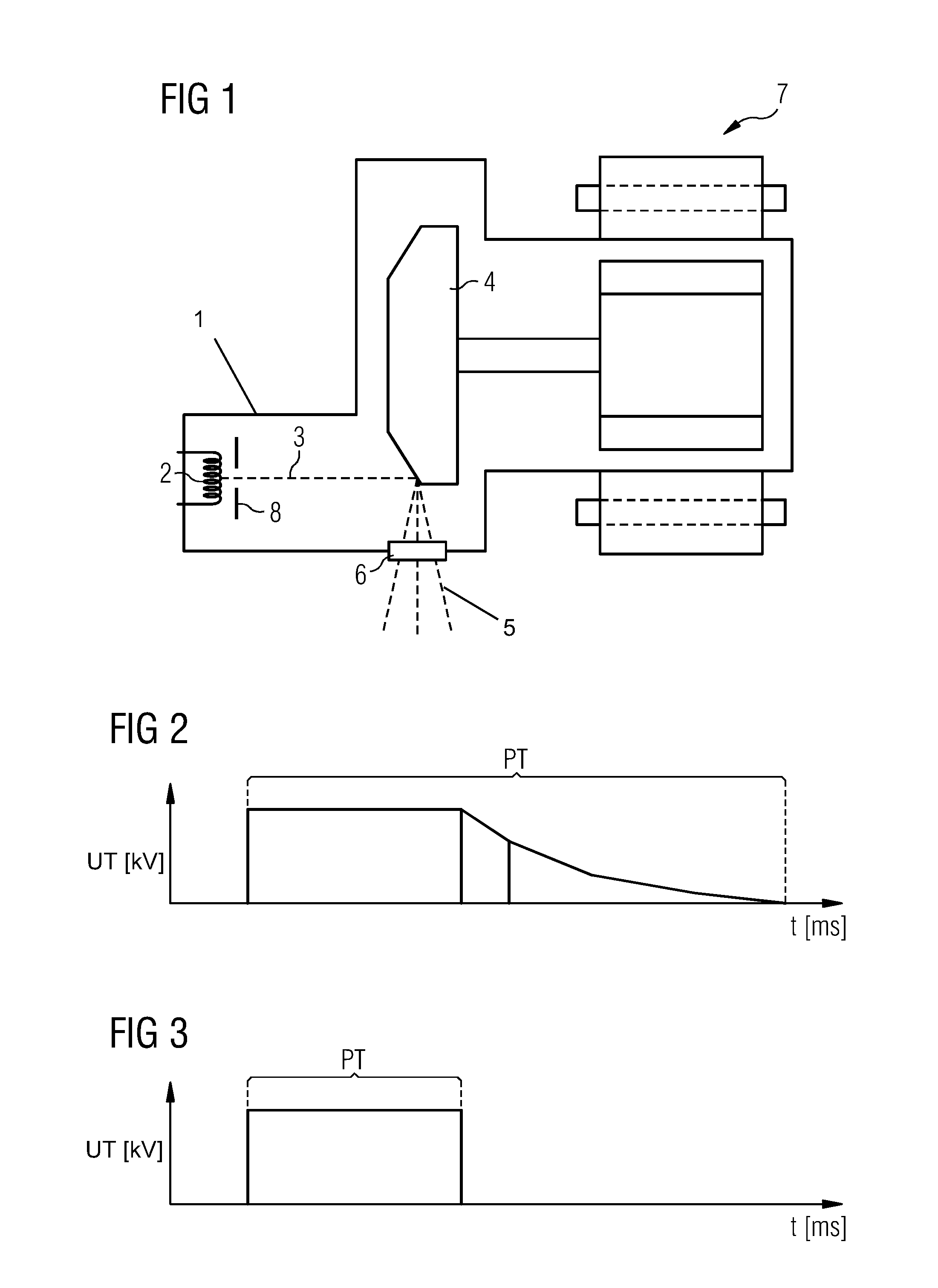
In X-ray-based imaging, X-ray emitters may be used as a particle source. Often, the X-ray emitters are pulsed in order, for example, to keep the patient dose low during medical imaging. The configuration of a known X-ray emitter or X-ray tube is depicted in FIG. 1.
FIG. 1 depicts a cross-section of an X-ray emitter. In a vacuum tube 1, electrons 3 are released into the vacuum by heating an emitter 2 (e.g. cathode). The electrons 3 are accelerated towards the anode 4 by a high voltage, that is applied between the emitter 2 and an anode 4. Upon striking the anode 4, approximately 1% of the energy of the electrons 3 is converted into X-ray radiation 5, the remaining energy transitioning into heat. The generated heat must be continuously extracted from the anode 4, otherwise there is a risk of the focal path melting on the anode 4. Therefore, in heavy-duty tubes, rotating anodes may be used in combination with directly cooled bearings. The X-ray radiation 5 exits the vacuum tube 1 through the outlet window 6. Using the motorized drive 7, the anode 4 is set in rotation.
For angiography, for example, a pulsed X-ray radiation is used to reduce the X-ray radiation exposure of the patient. The pulse generation for X-ray tubes may be realized by two methods.
A simple method is to switch the high voltage applied between the emitter 2 and the anode 4 on and off (primary pulsed X-ray radiation 5). Alternatively, a grating 8 may be arranged between the emitter 2 and the anode 4, or a metal element may be arranged around the emitter 2, that is exposed to a pulsed blocking voltage, and the electrons 3 are shielded toward the high voltage field. The grating 8 is switched on and off. The grating 8 alternately blocks and guides secondary pulsed X-ray radiation.
The first method is simple to realize. However, high capacities through cables etc. include disadvantage when actuating that the high capacities must be discharged via the X-ray tube causing electrons 3 to briefly strike the anode 4 with a lower energy, having experienced a lower acceleration voltage. The lower-energy electrons 3, however, generate a lower-energy X-ray radiation 5 that, in medical imaging for example, causes unnecessarily high patient doses without contributing to the imaging.
The second method creates clean X-ray pulses limited in terms of time, since the tube current are shielded in a very short switching time. A grating arrangement is disclosed by way of example in patent application DE 10 2009 004 186 A1. In heavy-duty X-ray tubes, however, the tube currents are very high. In order to generate such high tube currents, large emission surfaces of the emitter 2 are helpful. Large emission surfaces, however, are difficult to block. To this extent, a secondary pulsing is difficult in X-ray tubes with large currents.
SUMMARY AND DESCRIPTION
The scope of the present invention is defined solely by the appended claims and is not affected to any degree by the statements within this summary. The present embodiments may obviate one or more of the drawbacks or limitations in the related art.
Embodiments provide a method, a computer program product, a computer-readable medium and an apparatus for generating X-ray pulses during X-ray imaging. Embodiments provide that cleanly dispersed X-ray pulses may be generated even with high tube currents.
The high voltage of the X-ray tube is switched off. The high voltage decays rapidly with the strong currents in the X-ray tube.
As soon as the tube voltage has reached a threshold value, at which the emitter may be completely separated from the high voltage in terms of time by a grating, the grating is activated. The applied high voltage then remains at that value.
High currents may be used, while the lower-energy radiation that is undesirable in medical imaging is prevented.
In an embodiment, a method is provided for generating X-ray pulses during X-ray imaging. The high voltage of an X-ray tube is automatically switched off. The tube voltage decays. Upon reaching a predefined threshold value of the tube voltage or a predefined waiting time after switching off the high voltage, the grating voltage of a grating arranged between the emitter and the anode of the X-ray tube is automatically switched on. No electrons reach the anode from the emitter and the tube current drops to the value zero.
Embodiments allow for both high tube currents to be switched and lower-energy X-ray radiation to be prevented.
In an embodiment, the threshold value or the waiting time may be selected such that the emitter may be completely separated from the high voltage by the grating.
In a further embodiment, the threshold value or the waiting time may be determined experimentally or computationally.
Embodiments further provide a computer program product, including a computer program. The computer program may be loaded into a memory device of a control unit. The computer program may be used to carry out acts the method when the computer program is executed on the control unit.
Embodiments also provide a computer-readable medium, on which a computer program is stored. The computer program may be loaded into a memory device of a control unit. The computer program may be used to carry out the acts of the method when the computer program is executed on the control unit.
Embodiments further provide an apparatus for generating X-ray pulses during X-ray imaging. The apparatus includes an X-ray tube, a high voltage generation unit, a grating, a grating voltage generation unit, and a control unit. The X-ray tube includes an emitter and an anode. The high voltage generation unit is configured to build a high voltage between the emitter and the anode. The grating is located between the emitter and the anode and is configured to deflect the electrons of the emitter when a grating voltage is applied. The grating voltage generation unit is configured to build the grating voltage. The control unit is configured to automatically switch off the high voltage of the high voltage supply unit and, upon reaching a predefined threshold value of the tube voltage or a predefined waiting time after switching off the high voltage, to automatically switch on the grating voltage of the grating voltage generation unit.
In an embodiment, the apparatus includes a tube voltage measuring unit electrically connected to the control unit that is configured to calculate the tube voltage of the X-ray tube and transfer the tube voltage to the control unit.
BRIEF DESCRIPTION OF THE FIGURES
FIG. 1 depicts a cross-section of an X-ray tube.
FIG. 2 depicts a tube voltage UT in kV as a function of time in ms for a primary pulsed X-ray radiation according to an embodiment.
FIG. 3 depicts a tube voltage UT in kV as a function of time in ms for a secondary pulsed X-ray radiation according to an embodiment.
FIG. 4 depicts a flow diagram of an embodiment.
FIG. 5 depicts a tube current IT in A as a function of time in ms according to an embodiment.
FIG. 6 depicts a block diagram of an apparatus for generating X-ray pulses according to an embodiment.
DETAILED DESCRIPTION
FIG. 2 depicts exemplary tube voltage U.sub.T in kV as a function of time tin ms for a primary pulsed X-ray radiation in a graph. After the pulse duration PT, the high voltage is switched off, and the tube voltage drops to the value zero after some time.
FIG. 3 depicts exemplary tube voltage UT in kV as a function of the time tin ms for a secondary pulsed X-ray radiation in a graph. After the pulse duration PT, a grating voltage is switched on, and tube current IT immediately drops to the value zero, since no further electrons 3 may now reach the anode 4 from the emitter 2. The drop only happens, however, if the tube current or the tube voltage UT is not too great, as only then is the grating 8 fully effective and all electrons may be blocked. The X-ray pulse is cut off cleanly, as depicted in FIG. 3.
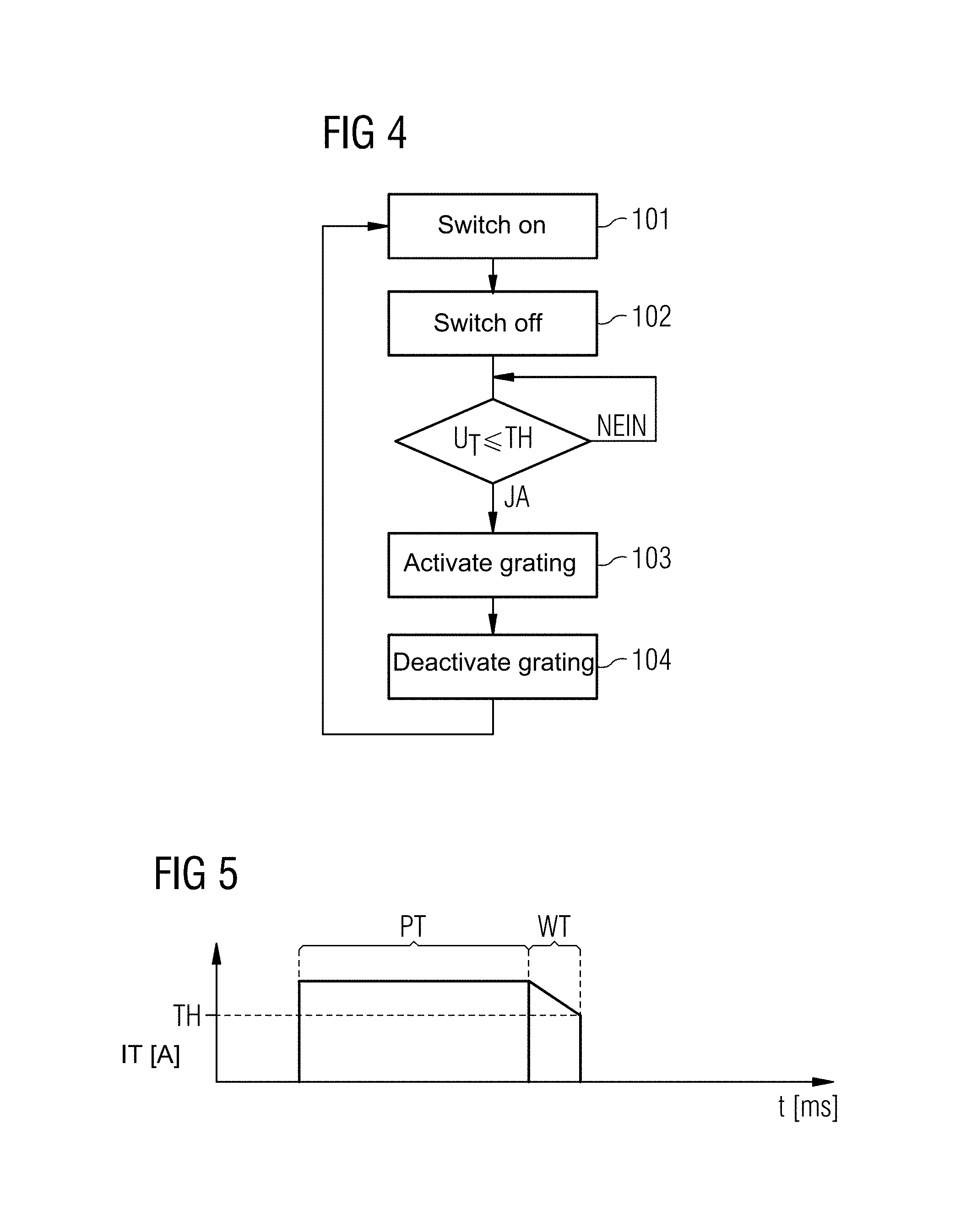
FIG. 4 depicts a flow diagram of one embodiment of a method for generating an X-ray pulse during X-ray imaging. In act 101, the high voltage of the X-ray tube is switched on. In act 102, the high voltage is switched off after the pulse duration PT has expired. Once the tube voltage UT has reached the threshold value TH, the grating 8 is activated in act 103. The tube current IT drops to the value zero. After a pause, in act 104 the grating 8 is deactivated, and the method jumps again to act 101.
The method results in a graph according to FIG. 5. The tube current IT in A is depicted as a function of the time t in ms. The high voltage is switched off after the pulse duration PT and, when the tube voltage UT has reached the threshold value TH, the grating 8 is activated by switching on the grating voltage and the tube current IT drops to the value zero. The resulting pulse duration is therefore composed of the pulse duration PT and the waiting time WT. Only high-energy quanta are generated, although the quanta also travel with large tube currents.
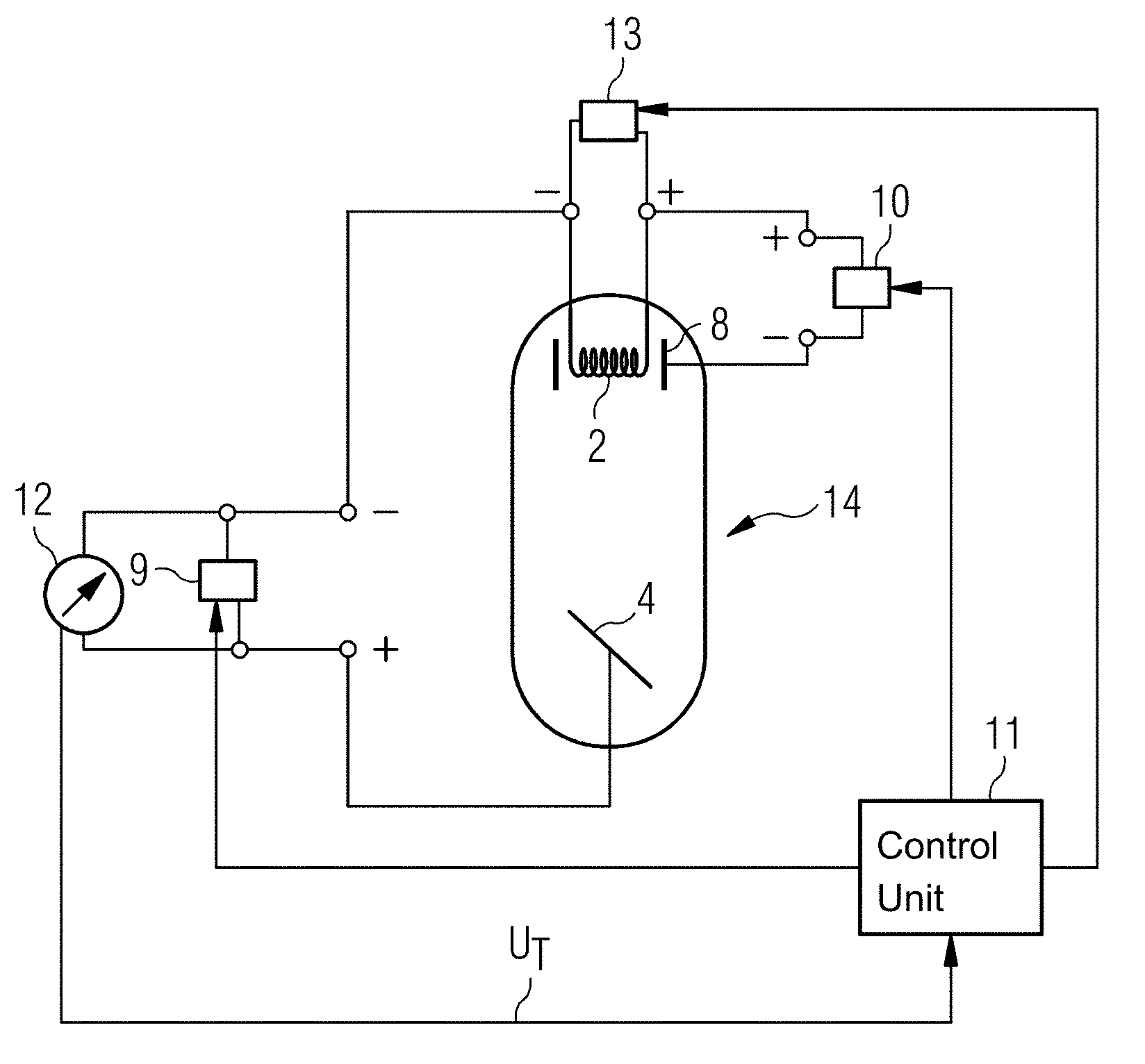
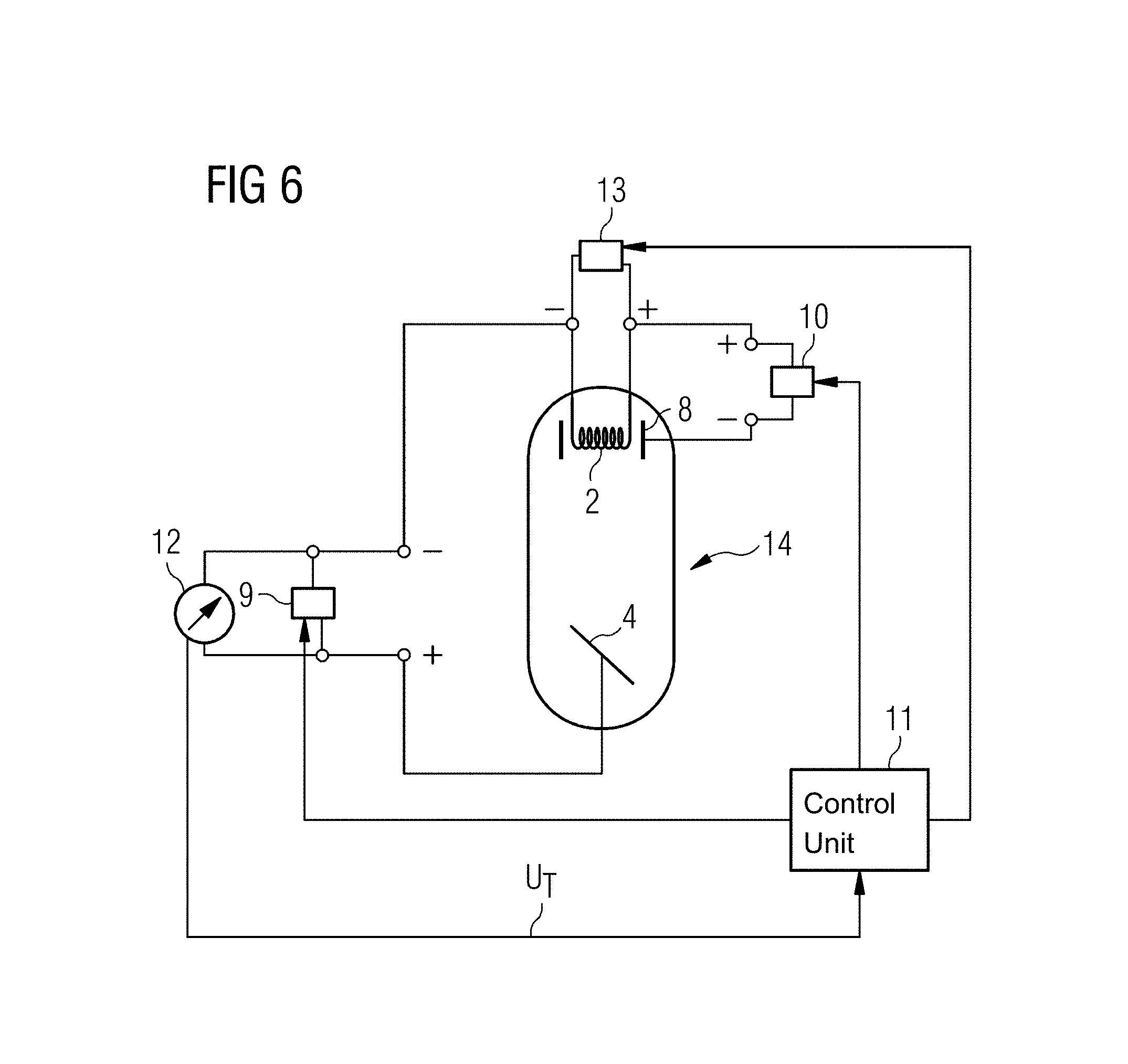
FIG. 6 depicts a block diagram of an apparatus for generating an X-ray pulse during X-ray imaging. The emitter 2 of an X-ray tube 14 is made to anneal with a heating voltage generation unit 13. The high voltage of the high voltage generation unit 9 is applied between the emitter 2 and the anode 4. The grating 8 is powered by the grating voltage generation unit 10. With the aid of the tube voltage measuring unit 12, the tube voltage U.sub.T may be measured. The aforementioned components are controlled by a control unit 11 (e.g., a controller).
The current tube voltage U.sub.T is supplied to the control unit 11 by the tube voltage measuring unit 12. When the previously calculated threshold value TH of the tube voltage U.sub.T is reached, the grating 8 is activated via the control unit 11. Alternatively, after a previously calculated waiting time WT, the grating 8 may be activated. The tube current no longer flows. The X-ray pulse is cut off cleanly. Subsequently, the grating 8 is deactivated, and the high voltage is switched on again.
It is to be understood that the elements and features recited in the appended claims may be combined in different ways to produce new claims that likewise fall within the scope of the present invention. Thus, whereas the dependent claims appended below depend from only a single independent or dependent claim, it is to be understood that these dependent claims may, alternatively, be made to depend in the alternative from any preceding or following claim, whether independent or dependent, and that such new combinations are to be understood as forming a part of the present specification.
While the present invention has been described above by reference to various embodiments, it may be understood that many changes and modifications may be made to the described embodiments. It is therefore intended that the foregoing description be regarded as illustrative rather than limiting, and that it be understood that all equivalents and/or combinations of embodiments are intended to be included in this description.
* * * * *
D00000
D00001
D00002
D00003
XML
uspto.report is an independent third-party trademark research tool that is not affiliated, endorsed, or sponsored by the United States Patent and Trademark Office (USPTO) or any other governmental organization. The information provided by uspto.report is based on publicly available data at the time of writing and is intended for informational purposes only.
While we strive to provide accurate and up-to-date information, we do not guarantee the accuracy, completeness, reliability, or suitability of the information displayed on this site. The use of this site is at your own risk. Any reliance you place on such information is therefore strictly at your own risk.
All official trademark data, including owner information, should be verified by visiting the official USPTO website at www.uspto.gov. This site is not intended to replace professional legal advice and should not be used as a substitute for consulting with a legal professional who is knowledgeable about trademark law.