Back to back electronic display assembly
Dunn , et al. Ja
U.S. patent number 10,194,564 [Application Number 14/700,519] was granted by the patent office on 2019-01-29 for back to back electronic display assembly. This patent grant is currently assigned to Manufacturing Resources International, Inc.. The grantee listed for this patent is Manufacturing Resources International, Inc.. Invention is credited to Kyle Azevedo, Marcos Diaz, William Dunn.


| United States Patent | 10,194,564 |
| Dunn , et al. | January 29, 2019 |
Back to back electronic display assembly
Abstract
The exemplary embodiments herein comprise a back to back electronic display assembly having a first display assembly positioned back to back with a second display assembly. A plenum is preferably positioned in between the first and second display assemblies with a first gap defined between the plenum and the first display assembly and a second gap defined between the plenum and the second display assembly. A fan is preferably positioned to force air through the first and second gaps. A plenum fan may be used to circulate air around the plenum. Preferably, the second display assembly can move relative to the first display assembly to provide access to the interior of the plenum.
| Inventors: | Dunn; William (Alpharetta, GA), Diaz; Marcos (Alpharetta, GA), Azevedo; Kyle (Alpharetta, GA) | ||||||||||
|---|---|---|---|---|---|---|---|---|---|---|---|
| Applicant: |
|
||||||||||
| Assignee: | Manufacturing Resources
International, Inc. (Alpharetta, GA) |
||||||||||
| Family ID: | 54356281 | ||||||||||
| Appl. No.: | 14/700,519 | ||||||||||
| Filed: | April 30, 2015 |
Prior Publication Data
| Document Identifier | Publication Date | |
|---|---|---|
| US 20150319882 A1 | Nov 5, 2015 | |
Related U.S. Patent Documents
| Application Number | Filing Date | Patent Number | Issue Date | ||
|---|---|---|---|---|---|
| 61986724 | Apr 30, 2014 | ||||
| Current U.S. Class: | 1/1 |
| Current CPC Class: | G02F 1/133308 (20130101); H05K 7/20972 (20130101); H05K 5/0017 (20130101); F21V 29/677 (20150115); G02F 1/133385 (20130101); G02F 1/1336 (20130101); H05K 7/20145 (20130101); H05K 5/0226 (20130101); F21Y 2115/10 (20160801); G02F 2001/133331 (20130101); G02F 2001/133628 (20130101) |
| Current International Class: | H05K 5/00 (20060101); F21V 29/67 (20150101); H05K 7/20 (20060101); G02F 1/1333 (20060101) |
| Field of Search: | ;362/97.1,97.2 |
References Cited [Referenced By]
U.S. Patent Documents
| 4093355 | June 1978 | Kaplit et al. |
| 4593978 | June 1986 | Mourey et al. |
| 4634225 | January 1987 | Haim et al. |
| 4748765 | June 1988 | Martin |
| 4763993 | August 1988 | Vogeley et al. |
| 4921041 | May 1990 | Akachi |
| 4952783 | August 1990 | Aufderheide et al. |
| 4952925 | August 1990 | Haastert |
| 5029982 | July 1991 | Nash |
| 5088806 | February 1992 | McCartney et al. |
| 5132666 | July 1992 | Fahs |
| 5247374 | September 1993 | Terada |
| 5282114 | January 1994 | Stone |
| 5293930 | March 1994 | Pitasi |
| 5351176 | September 1994 | Smith et al. |
| 5432526 | July 1995 | Hyatt |
| 5535816 | July 1996 | Ishida |
| 5559614 | September 1996 | Urbish et al. |
| 5621614 | April 1997 | O'Neill |
| 5657641 | August 1997 | Cunningham et al. |
| 5748269 | May 1998 | Harris et al. |
| 5765743 | June 1998 | Sakiura et al. |
| 5767489 | June 1998 | Ferrier |
| 5808418 | September 1998 | Pitman et al. |
| 5818010 | October 1998 | McCann |
| 5818694 | October 1998 | Daikoku et al. |
| 5835179 | November 1998 | Yamanaka |
| 5864465 | January 1999 | Liu |
| 5869818 | February 1999 | Kim |
| 5869919 | February 1999 | Sato et al. |
| 5903433 | May 1999 | Gudmundsson |
| 5991153 | November 1999 | Heady et al. |
| 6003015 | December 1999 | Kang et al. |
| 6007205 | December 1999 | Fujimori |
| 6089751 | July 2000 | Conover et al. |
| 6104451 | August 2000 | Matsuoka et al. |
| 6157432 | December 2000 | Helbing |
| 6181070 | January 2001 | Dunn et al. |
| 6191839 | February 2001 | Briley et al. |
| 6198222 | March 2001 | Chang |
| 6211934 | April 2001 | Habing et al. |
| 6215655 | April 2001 | Heady et al. |
| 6351381 | February 2002 | Bilski et al. |
| 6392727 | May 2002 | Larson et al. |
| 6417900 | July 2002 | Shin et al. |
| 6428198 | August 2002 | Saccomanno et al. |
| 6437673 | August 2002 | Nishida |
| 6473150 | October 2002 | Takushima et al. |
| 6493440 | December 2002 | Gromatsky et al. |
| 6504713 | January 2003 | Pandolfi et al. |
| 6535266 | March 2003 | Nemeth et al. |
| 6628355 | September 2003 | Takahara |
| 6683639 | January 2004 | Scheper |
| 6714410 | March 2004 | Wellhofer |
| 6727468 | April 2004 | Nemeth |
| 6825828 | November 2004 | Burke et al. |
| 6839104 | January 2005 | Taniguchi et al. |
| 6885412 | April 2005 | Ohnishi et al. |
| 6886942 | May 2005 | Okada et al. |
| 6891135 | May 2005 | Pala et al. |
| 6909486 | June 2005 | Wang et al. |
| 6943768 | September 2005 | Cavanaugh et al. |
| 6961108 | November 2005 | Wang et al. |
| 7015470 | March 2006 | Faytlin et al. |
| 7059757 | June 2006 | Shimizu |
| 7083285 | August 2006 | Hsu et al. |
| 7157838 | January 2007 | Thielemans et al. |
| 7161803 | January 2007 | Heady |
| 7190587 | March 2007 | Kim et al. |
| 7209349 | April 2007 | Chien et al. |
| 7212403 | May 2007 | Rockenfell |
| 7259964 | August 2007 | Yamamura et al. |
| 7269023 | September 2007 | Nagano |
| 7284874 | October 2007 | Jeong et al. |
| 7452121 | November 2008 | Cho et al. |
| 7457113 | November 2008 | Kumhyr et al. |
| 7480140 | January 2009 | Hara et al. |
| 7535543 | May 2009 | Dewa et al. |
| 7591508 | September 2009 | Chang |
| 7602469 | October 2009 | Shin |
| D608775 | January 2010 | Leung |
| 7667964 | February 2010 | Kang et al. |
| 7752858 | July 2010 | Johnson et al. |
| 7753567 | July 2010 | Kang et al. |
| 7800706 | September 2010 | Kim et al. |
| 7813124 | October 2010 | Karppanen |
| 7903416 | March 2011 | Chou |
| 7995342 | August 2011 | Nakamichi et al. |
| 8004648 | August 2011 | Dunn |
| 8035968 | October 2011 | Kwon et al. |
| 8081465 | December 2011 | Nishiura |
| 8102173 | January 2012 | Merrow |
| 8142027 | March 2012 | Sakai |
| 8208115 | June 2012 | Dunn |
| 8223311 | July 2012 | Kim et al. |
| 8241573 | August 2012 | Banerjee et al. |
| 8248784 | August 2012 | Nakamichi et al. |
| 8254121 | August 2012 | Lee et al. |
| 8269916 | September 2012 | Ohkawa |
| 8270163 | September 2012 | Nakamichi et al. |
| 8274622 | September 2012 | Dunn |
| 8274789 | September 2012 | Nakamichi et al. |
| 8300203 | October 2012 | Nakamichi et al. |
| 8320119 | November 2012 | Isoshima et al. |
| 8351014 | January 2013 | Dunn |
| 8358397 | January 2013 | Dunn |
| 8369083 | February 2013 | Dunn et al. |
| 8373841 | February 2013 | Dunn |
| 8379182 | February 2013 | Dunn |
| 8400608 | March 2013 | Takahashi et al. |
| 8418387 | April 2013 | Swatt |
| 8472174 | June 2013 | Idems et al. |
| 8472191 | June 2013 | Yamamoto et al. |
| 8482695 | July 2013 | Dunn |
| 8497972 | July 2013 | Dunn et al. |
| 8649170 | February 2014 | Dunn et al. |
| 8649176 | February 2014 | Okada et al. |
| 8654302 | February 2014 | Dunn et al. |
| 8678603 | March 2014 | Zhang |
| 8693185 | April 2014 | Dunn et al. |
| 8700226 | April 2014 | Schuch et al. |
| 8711321 | April 2014 | Dunn et al. |
| 8749749 | June 2014 | Hubbard |
| 8755021 | June 2014 | Hubbard |
| 8760613 | June 2014 | Dunn |
| 8767165 | July 2014 | Dunn |
| 8773633 | July 2014 | Dunn et al. |
| 8804091 | August 2014 | Dunn et al. |
| 8823916 | September 2014 | Hubbard et al. |
| 8827472 | September 2014 | Takada |
| 8854572 | October 2014 | Dunn |
| 8854595 | October 2014 | Dunn |
| 8879042 | November 2014 | Dunn |
| 8976313 | March 2015 | Kim |
| 8988647 | March 2015 | Hubbard |
| 9030641 | May 2015 | Dunn |
| 9089079 | July 2015 | Dunn |
| 9119325 | August 2015 | Dunn et al. |
| 9119330 | August 2015 | Hubbard et al. |
| 9173322 | October 2015 | Dunn |
| 9173325 | October 2015 | Dunn |
| 9282676 | March 2016 | Diaz |
| 9285108 | March 2016 | Dunn et al. |
| 9313917 | April 2016 | Dunn et al. |
| 9370127 | June 2016 | Dunn |
| 9448569 | September 2016 | Schuch et al. |
| 9451060 | September 2016 | Bowers et al. |
| 9451733 | September 2016 | Dunn et al. |
| 9456525 | September 2016 | Yoon et al. |
| 9470924 | October 2016 | Dunn et al. |
| 9500896 | November 2016 | Dunn et al. |
| 9516485 | December 2016 | Bowers et al. |
| 9549490 | January 2017 | Hubbard |
| 9594271 | March 2017 | Dunn et al. |
| 9613548 | April 2017 | DeMars |
| 9622392 | April 2017 | Bowers et al. |
| 9629287 | April 2017 | Dunn |
| 9648790 | May 2017 | Dunn et al. |
| 9655289 | May 2017 | Dunn et al. |
| 9723765 | August 2017 | DeMars |
| 2001/0001459 | May 2001 | Savant et al. |
| 2001/0019454 | September 2001 | Tadic-Galeb et al. |
| 2002/0033919 | March 2002 | Sanelle et al. |
| 2002/0101553 | August 2002 | Enomoto et al. |
| 2002/0126248 | September 2002 | Yoshia |
| 2002/0148600 | October 2002 | Bosch et al. |
| 2002/0149714 | October 2002 | Anderson et al. |
| 2002/0154255 | October 2002 | Gromatzky et al. |
| 2002/0164944 | November 2002 | Haglid |
| 2002/0167637 | November 2002 | Burke et al. |
| 2003/0007109 | January 2003 | Park |
| 2003/0020884 | January 2003 | Okada et al. |
| 2003/0043091 | March 2003 | Takeuchi et al. |
| 2003/0104210 | June 2003 | Azumi et al. |
| 2003/0128511 | July 2003 | Nagashima et al. |
| 2003/0214785 | November 2003 | Perazzo |
| 2004/0012722 | January 2004 | Alvarez |
| 2004/0035558 | February 2004 | Todd et al. |
| 2004/0036834 | February 2004 | Ohnishi et al. |
| 2004/0103570 | June 2004 | Ruttenberg |
| 2004/0105159 | June 2004 | Saccomanno et al. |
| 2004/0165139 | August 2004 | Anderson et al. |
| 2004/0223299 | November 2004 | Ghosh |
| 2005/0012039 | January 2005 | Faytlin et al. |
| 2005/0012722 | January 2005 | Chon |
| 2005/0062373 | March 2005 | Kim et al. |
| 2005/0073632 | April 2005 | Dunn et al. |
| 2005/0073639 | April 2005 | Pan |
| 2005/0127796 | June 2005 | Olesen |
| 2005/0134525 | June 2005 | Tanghe et al. |
| 2005/0134526 | June 2005 | Willem et al. |
| 2005/0213950 | September 2005 | Yoshimura |
| 2005/0229630 | October 2005 | Richter et al. |
| 2005/0237714 | October 2005 | Ebermann |
| 2005/0276053 | December 2005 | Nortrup et al. |
| 2005/0286131 | December 2005 | Saxena et al. |
| 2006/0012958 | January 2006 | Tomioka et al. |
| 2006/0012985 | January 2006 | Archie |
| 2006/0018093 | January 2006 | Lai et al. |
| 2006/0034051 | February 2006 | Wang et al. |
| 2006/0056994 | March 2006 | Van Lear et al. |
| 2006/0082271 | April 2006 | Lee et al. |
| 2006/0092346 | May 2006 | Moon |
| 2006/0092348 | May 2006 | Park |
| 2006/0125998 | June 2006 | Dewa et al. |
| 2006/0132699 | June 2006 | Cho et al. |
| 2006/0177587 | August 2006 | Ishizuka et al. |
| 2006/0199514 | September 2006 | Kimura |
| 2006/0209266 | September 2006 | Utsunomiya |
| 2006/0260790 | November 2006 | Theno et al. |
| 2006/0262079 | November 2006 | Seong et al. |
| 2006/0266499 | November 2006 | Choi et al. |
| 2006/0269216 | November 2006 | Wiemeyer |
| 2006/0283579 | December 2006 | Ghosh et al. |
| 2007/0019419 | January 2007 | Hafuka et al. |
| 2007/0030879 | February 2007 | Hatta |
| 2007/0047239 | March 2007 | Kang et al. |
| 2007/0065091 | March 2007 | Hinata et al. |
| 2007/0076431 | April 2007 | Atarashi et al. |
| 2007/0103863 | May 2007 | Kim |
| 2007/0103866 | May 2007 | Park |
| 2007/0115686 | May 2007 | Tyberghien |
| 2007/0139929 | June 2007 | Yoo et al. |
| 2007/0140671 | June 2007 | Yoshimura |
| 2007/0151274 | July 2007 | Roche et al. |
| 2007/0151664 | July 2007 | Shin |
| 2007/0171353 | July 2007 | Hong |
| 2007/0206158 | September 2007 | Kinoshita et al. |
| 2007/0211205 | September 2007 | Shibata |
| 2007/0212211 | September 2007 | Chiyoda et al. |
| 2007/0217221 | September 2007 | Lee et al. |
| 2007/0237636 | October 2007 | Hsu |
| 2007/0267174 | November 2007 | Kim |
| 2008/0055534 | March 2008 | Kawano |
| 2008/0076342 | March 2008 | Bryant et al. |
| 2008/0099193 | May 2008 | Aksamit et al. |
| 2008/0148609 | June 2008 | Ogoreve |
| 2008/0209934 | September 2008 | Richards |
| 2008/0218446 | September 2008 | Yamanaka |
| 2008/0236005 | October 2008 | Isayev et al. |
| 2008/0267790 | October 2008 | Gaudet et al. |
| 2008/0283234 | November 2008 | Sagi et al. |
| 2008/0285290 | November 2008 | Ohashi et al. |
| 2009/0009729 | January 2009 | Sakai |
| 2009/0086430 | April 2009 | Kang et al. |
| 2009/0120629 | May 2009 | Ashe |
| 2009/0126906 | May 2009 | Dunn |
| 2009/0126907 | May 2009 | Dunn |
| 2009/0126914 | May 2009 | Dunn |
| 2009/0135365 | May 2009 | Dunn |
| 2009/0147170 | June 2009 | Oh et al. |
| 2009/0154096 | June 2009 | Iyengar et al. |
| 2009/0174626 | July 2009 | Isoshima et al. |
| 2009/0244472 | October 2009 | Dunn |
| 2009/0279240 | November 2009 | Karppanen |
| 2009/0306820 | December 2009 | Simmons et al. |
| 2010/0060861 | March 2010 | Medin |
| 2010/0079949 | April 2010 | Nakamichi et al. |
| 2010/0162747 | July 2010 | Hamel et al. |
| 2010/0171889 | July 2010 | Pantel et al. |
| 2010/0182562 | July 2010 | Yoshida et al. |
| 2010/0220249 | September 2010 | Nakamichi et al. |
| 2010/0226091 | September 2010 | Dunn |
| 2010/0232107 | September 2010 | Dunn |
| 2010/0238394 | September 2010 | Dunn |
| 2010/0321887 | December 2010 | Kwon et al. |
| 2011/0001898 | January 2011 | Mikubo et al. |
| 2011/0013114 | January 2011 | Dunn et al. |
| 2011/0019363 | January 2011 | Vahlsing et al. |
| 2011/0051071 | March 2011 | Nakamichi et al. |
| 2011/0058326 | March 2011 | Idems et al. |
| 2011/0075361 | March 2011 | Nakamichi et al. |
| 2011/0083460 | April 2011 | Thomas et al. |
| 2011/0083824 | April 2011 | Rogers |
| 2011/0085301 | April 2011 | Dunn |
| 2011/0114384 | May 2011 | Sakamoto et al. |
| 2011/0116000 | May 2011 | Dunn et al. |
| 2011/0116231 | May 2011 | Dunn et al. |
| 2011/0122162 | May 2011 | Sato et al. |
| 2011/0134356 | June 2011 | Swatt |
| 2011/0141724 | June 2011 | Erion |
| 2011/0261523 | October 2011 | Dunn et al. |
| 2012/0006523 | January 2012 | Masahiro et al. |
| 2012/0012295 | January 2012 | Kakiuchi et al. |
| 2012/0012300 | January 2012 | Dunn et al. |
| 2012/0014063 | January 2012 | Weiss |
| 2012/0020114 | January 2012 | Miyamoto et al. |
| 2012/0038849 | February 2012 | Dunn et al. |
| 2012/0044217 | February 2012 | Okada et al. |
| 2012/0106081 | May 2012 | Hubbard et al. |
| 2012/0206687 | August 2012 | Dunn et al. |
| 2012/0249402 | October 2012 | Kang |
| 2012/0255704 | October 2012 | Nakamichi |
| 2012/0274876 | November 2012 | Cappaert et al. |
| 2012/0284547 | November 2012 | Culbert et al. |
| 2013/0170140 | July 2013 | Dunn |
| 2013/0201685 | August 2013 | Messmore et al. |
| 2013/0258659 | October 2013 | Erion |
| 2013/0294039 | November 2013 | Chao |
| 2014/0044147 | February 2014 | Wyatt |
| 2014/0085564 | March 2014 | Hendren et al. |
| 2014/0111758 | April 2014 | Dunn et al. |
| 2014/0113540 | April 2014 | Dunn et al. |
| 2014/0118221 | May 2014 | Park |
| 2014/0313698 | October 2014 | Dunn et al. |
| 2014/0314395 | October 2014 | Dunn |
| 2015/0253611 | September 2015 | Yang |
| 2015/0264826 | September 2015 | Dunn et al. |
| 2015/0319882 | November 2015 | Dunn et al. |
| 2015/0366101 | December 2015 | Dunn et al. |
| 2016/0041423 | February 2016 | Dunn |
| 2016/0044829 | February 2016 | Dunn |
| 2016/0192536 | June 2016 | Diaz |
| 2016/0195254 | July 2016 | Dunn et al. |
| 2016/0198588 | July 2016 | DeMars |
| 2016/0238876 | August 2016 | Dunn et al. |
| 2016/0242329 | August 2016 | DeMars |
| 2016/0242330 | August 2016 | Dunn |
| 2016/0249493 | August 2016 | Dunn et al. |
| 2016/0302331 | October 2016 | Dunn |
| 2017/0023823 | January 2017 | Dunn et al. |
| 2017/0068042 | March 2017 | Dunn et al. |
| 2017/0074453 | March 2017 | Bowers et al. |
| 2017/0083043 | March 2017 | Bowers et al. |
| 2017/0083062 | March 2017 | Bowers et al. |
| 2017/0111486 | April 2017 | Bowers et al. |
| 2017/0111520 | April 2017 | Bowers et al. |
| 2017/0111521 | April 2017 | Bowers et al. |
| 2017/0127579 | May 2017 | Hubbard |
| 2017/0188490 | June 2017 | Dunn et al. |
| 2017/0245400 | August 2017 | Dunn et al. |
| 2017/0257978 | September 2017 | Diaz |
| 2011248190 | May 2011 | AU | |||
| 2014287438 | Jan 2018 | AU | |||
| 2702363 | May 2005 | CN | |||
| 1408476 | Apr 2004 | EP | |||
| 1647766 | Apr 2006 | EP | |||
| 1647766 | Apr 2006 | EP | |||
| 1762892 | Mar 2007 | EP | |||
| 1951020 | Jul 2008 | EP | |||
| 2225603 | Sep 2010 | EP | |||
| 2370987 | Oct 2011 | EP | |||
| 2603831 | Jun 2013 | EP | |||
| 2801888 | Nov 2014 | EP | |||
| 2909829 | Aug 2015 | EP | |||
| 3020260 | May 2016 | EP | |||
| 3117693 | Jan 2017 | EP | |||
| 2402205 | Dec 2004 | GB | |||
| 2402205 | Dec 2004 | GB | |||
| 402062015 | Mar 1990 | JP | |||
| 402307080 | Dec 1990 | JP | |||
| 03153212 | Jul 1991 | JP | |||
| 3153212 | Jul 1991 | JP | |||
| H06-2337 | Jan 1994 | JP | |||
| 6082745 | Mar 1994 | JP | |||
| 8115788 | May 1996 | JP | |||
| 08194437 | Jul 1996 | JP | |||
| 8194437 | Jul 1996 | JP | |||
| H08-305301 | Nov 1996 | JP | |||
| 8339034 | Dec 1996 | JP | |||
| H09246766 | Sep 1997 | JP | |||
| 11160727 | Jun 1999 | JP | |||
| 11160727 | Jun 1999 | JP | |||
| 11296094 | Oct 1999 | JP | |||
| H11296094 | Oct 1999 | JP | |||
| 2001209126 | Aug 2001 | JP | |||
| 2001209126 | Aug 2001 | JP | |||
| 2002158475 | May 2002 | JP | |||
| 2002158475 | May 2002 | JP | |||
| 2004053749 | Feb 2004 | JP | |||
| 2005017556 | Jan 2005 | JP | |||
| 2000131682 | May 2005 | JP | |||
| 2005134849 | May 2005 | JP | |||
| 2005134849 | May 2005 | JP | |||
| 2005-265922 | Sep 2005 | JP | |||
| 2005265922 | Sep 2005 | JP | |||
| 2006513577 | Apr 2006 | JP | |||
| 2007322718 | May 2006 | JP | |||
| 2006148047 | Jun 2006 | JP | |||
| 2006163217 | Jun 2006 | JP | |||
| 2007003638 | Jan 2007 | JP | |||
| 2007-293105 | Nov 2007 | JP | |||
| 09307257 | Nov 2007 | JP | |||
| 09307257 | Nov 2007 | JP | |||
| 2008010361 | Jan 2008 | JP | |||
| 2008292743 | Dec 2008 | JP | |||
| 2008292743 | Dec 2008 | JP | |||
| 2010024624 | Feb 2010 | JP | |||
| 2010024624 | Feb 2010 | JP | |||
| 2017518526 | Jul 2017 | JP | |||
| 200366674 | Nov 2004 | KR | |||
| 20050033986 | Apr 2005 | KR | |||
| 20050033986 | Apr 2005 | KR | |||
| 200401354 | Nov 2005 | KR | |||
| 20060016469 | Feb 2006 | KR | |||
| 20060016469 | Feb 2006 | KR | |||
| 100666961 | Jan 2007 | KR | |||
| 100666961 | Jan 2007 | KR | |||
| 1020070070675 | Apr 2007 | KR | |||
| 1020070070675 | Jul 2007 | KR | |||
| 1020070048294 | Aug 2007 | KR | |||
| 101764381 | Jul 2017 | KR | |||
| 2513043 | Apr 2014 | RU | |||
| WO2005079129 | Aug 2005 | WO | |||
| WO2005079129 | Aug 2005 | WO | |||
| WO2007116116 | Oct 2007 | WO | |||
| WO2008050660 | May 2008 | WO | |||
| WO2009065125 | May 2009 | WO | |||
| WO2009065125 | May 2009 | WO | |||
| WO2009135308 | Nov 2009 | WO | |||
| WO2009135308 | Nov 2009 | WO | |||
| WO2010-007821 | Jan 2010 | WO | |||
| WO2010007821 | Feb 2010 | WO | |||
| WO2010080624 | Jul 2010 | WO | |||
| WO2011069084 | Jun 2011 | WO | |||
| WO2011072217 | Jun 2011 | WO | |||
| WO2011140179 | Nov 2011 | WO | |||
| WO2011150078 | Dec 2011 | WO | |||
| WO2012021573 | Feb 2012 | WO | |||
| WO2012024426 | Feb 2012 | WO | |||
| WO2014149773 | Sep 2014 | WO | |||
| WO2014150036 | Sep 2014 | WO | |||
| WO2015168375 | Nov 2015 | WO | |||
| WO2016102982 | Jun 2016 | WO | |||
| WO2016133852 | Aug 2016 | WO | |||
| WO2017152166 | Sep 2017 | WO | |||
Other References
|
Zeef, Hubing, EMC analysis of 18' LCD Monitor, Aug. 2000, 1 page. cited by applicant . ITSENCLOSURES, Product Catalog, 2009, 48 pages. cited by applicant . ITSENCLOSURES, Standard Product Data Sheet, 2011, 18 pages. cited by applicant . SUNBRITETV, All Weather Outdoor LCD Television Model 4610HD, 2008, 1 page. cited by applicant . SUNBRITETV, Introduces Two New All-Weather Outdoor Televisions InfoComm 2008, 7 pages. cited by applicant . ITSENCLOSURES, Viewstation, 2017, 16 pages. cited by applicant . Novitsky, Driving LEDs versus CCFLs for LCD backlighting, Nov. 12, 2007, 6 pages. cited by applicant . Federman, Cooling Flat Panel Displays, 2011, 4 pages. cited by applicant . Zeeff, T.M., EMC analysis of an 18'' LCD monitor, 2000, 1 page. cited by applicant . Wankhede, Evaluation of Cooling Solutions for Outdoor Electronics, Sep. 17-19, 2007, 6 pages. cited by applicant . Bureau of Ships Navy Department, Guide Manual of Cooling methods for Electronic Equipment, Mar. 31, 1955, 212 pages. cited by applicant . Scott, Cooling of Electronic Equipment, Apr. 4, 1947, 119 pages. cited by applicant . Sergent, Thermal Management Handbook for Electronic Assemblies, Aug. 14, 1998, 190 pages. cited by applicant . Steinberg, Cooling Techniques for Electronic Equipment First Edition, 1980, 255 pages. cited by applicant . Steinberg, Cooling Techniques for Electronic Equipment Second Edition, 1991, 299 pages. cited by applicant . Yeh, Thermal Management of Microelectronic Equipment, Oct. 15, 2002, 148 pages. cited by applicant . Civiq Smartscapes LLC. V Manufacturing Resources International, Inc., Defendant's Amended Answer and Countercliams to Plaintiff's First Amended Complaint, Filed Apr. 24, 2018, 240 pages. cited by applicant . Yung, Using Metal Core Printed Circuit Board as a Solution for Thermal Management article, 2007, 5 pages. cited by applicant . Civiq, Invalidity Claim Charts, Appendix F to H, Mar. 22, 2018, 18 pages. cited by applicant . Civiq, Invalidity Claim Charts, Appendix A-Appendix D, Jan. 24, 2018, 51 pages. cited by applicant . Civiq, Invalidity Claim Chart, Appendix I, Mar. 22, 2018, 4 pages. cited by applicant . Civiq, Invalidity Contentions, Jan. 24, 2018, 51 pages. cited by applicant . Mentley, David E., State of Flat-Panel Display Technology and Future Trends, Proceedings of the IEEE, Apr. 2002, vol. 90, No. 4, pp. 453-459. cited by applicant . Rohsenow, Warren M., Handbook of Heat Transfer, Third Edition, 1998, select chapters, 112 pages, McGraw-Hill. cited by applicant . The American Heritage College Dictionary, Third Edition, 1993, excerpt, 3 pages, Houghton Mifflin Company. cited by applicant . Civiq Smartscapes LLC. V Manufacturing Resources International, Inc., Petition for Inter Partes Review of U.S. Pat. No. 8,854,572 including Declaration of Greg Blonder in Support of Petition, Curriculum Vitae of Greg Blonder and Prosecution History of U.S. Pat. No. 8,854,572, Petition filed Mar. 14, 2018, 427 pages. cited by applicant. |
Primary Examiner: Neils; Peggy A
Attorney, Agent or Firm: Standley Law Group LLP
Parent Case Text
CROSS-REFERENCE TO RELATED APPLICATIONS
This application claims priority to U.S. Application No. 61/986,724 filed on Apr. 30, 2014 and is herein incorporated by reference in its entirety.
Claims
We claim:
1. A back to back electronic display assembly comprising: a first display assembly positioned back to back with a second display assembly; an enclosed chamber positioned entirely between the first and second display assemblies, wherein said enclosed chamber is substantially sealed to prevent circulating air located within the enclosed chamber from exiting the enclosed chamber; a first gap defined between the enclosed chamber and the first display assembly; a second gap defined between the enclosed chamber and the second display assembly; and a fan positioned to force external air through the first and second gaps.
2. The assembly of claim 1 further comprising: a chamber fan positioned within the enclosed chamber.
3. The assembly of claim 1 wherein: one or more electronic components for operating the first display positioned within the enclosed chamber.
4. The assembly of claim 3 wherein: the electronic component is a power module.
5. The assembly of claim 1 wherein: the enclosed chamber comprises a first wall and second wall which oppose each other, a top wall, bottom wall, and a pair of sidewalls.
6. The assembly of claim 5 further comprising: a gasket positioned between the top wall and the second wall.
7. The assembly of claim 1 wherein: the second display assembly is permitted to move relative to the first display assembly.
8. The assembly of claim 5 wherein: the first wall is fixed relative to the first display assembly; and the second wall is fixed relative to the second display assembly.
9. The assembly of claim 5 wherein: the first gap is further defined between the first wall of the enclosed chamber and an LED backlight for the first display assembly; and the second gap is further defined between the second wall of the enclosed chamber and an LED backlight for the second display assembly.
10. The assembly of claim 1 further comprising: a first dividing wall positioned within the enclosed chamber; and a second dividing wall positioned within the enclosed chamber and oriented substantially perpendicular to the first dividing wall.
11. The assembly of claim 10 further comprising: a chamber fan positioned within the first or second dividing wall.
12. A back to back electronic display assembly comprising: a first LED backlit display positioned back to back with a second LED backlit display; an enclosed chamber positioned entirely between the first and second LED backlit displays and comprising: a first wall which faces a first LED backlight, a second wall which faces a second LED backlight, a top wall, a bottom wall, and a pair of sidewalls which extend between the first wall and the second wall, wherein said enclosed chamber is substantially sealed from external air; a first gap defined by the space between the first wall and the first LED backlight; a second gap defined by the space between the second wall and the second LED backlight; an electronic component attached to the first wall or second wall; a first fan positioned to force external air through the first gap and the second gap; a dividing wall positioned within the enclosed chamber that connects between the first wall and second wall of the enclosed chamber; a second fan positioned on the dividing wall for moving circulating gas through the enclosed chamber; and an additional dividing wall within the enclosed chamber which is connected to the first dividing wall and connects between the first wall and second wall of the enclosed chamber.
13. The assembly of claim 12 wherein: the first wall is fixed relative to the first display; and the second wall is fixed relative to the second display.
Description
TECHNICAL FIELD
Embodiments generally relate to cooling systems and methods for installing electronic displays.
BACKGROUND OF THE ART
Electronic displays are sometimes used in outdoor environments or other areas where the surrounding temperatures may be high or there may be other sources of heat such as solar loading causing the temperatures within the display to rise. However, some portions of the display can be difficult to cool as simply ingesting ambient air into some portions of the display can introduce dust and contaminates into sensitive portions of the display, which can lead to premature failures. In some spaces, only a small footprint is available, such that placing electronic displays in a back to back orientation is desirable.
SUMMARY OF THE EXEMPLARY EMBODIMENTS
Exemplary embodiments provide a back to back electronic display assembly where the electronic components are contained within a sealed plenum. External air is ingested and passed between the walls of the plenum and the rear surfaces of the electronic display assemblies. The two electronic display assemblies are permitted to move relative to one another, such that the plenum can be easily opened with the electronics made available for servicing and/or replacement.
The foregoing and other features and advantages of the present invention will be apparent from the following more detailed description of the particular embodiments, as illustrated in the accompanying drawings.
BRIEF DESCRIPTION OF THE DRAWINGS
A better understanding of an exemplary embodiment will be obtained from a reading of the following detailed description and the accompanying drawings wherein identical reference characters refer to identical parts and in which:
FIG. 1 is a front planar view of an exemplary back to back display assembly showing the vertical section line A-A.
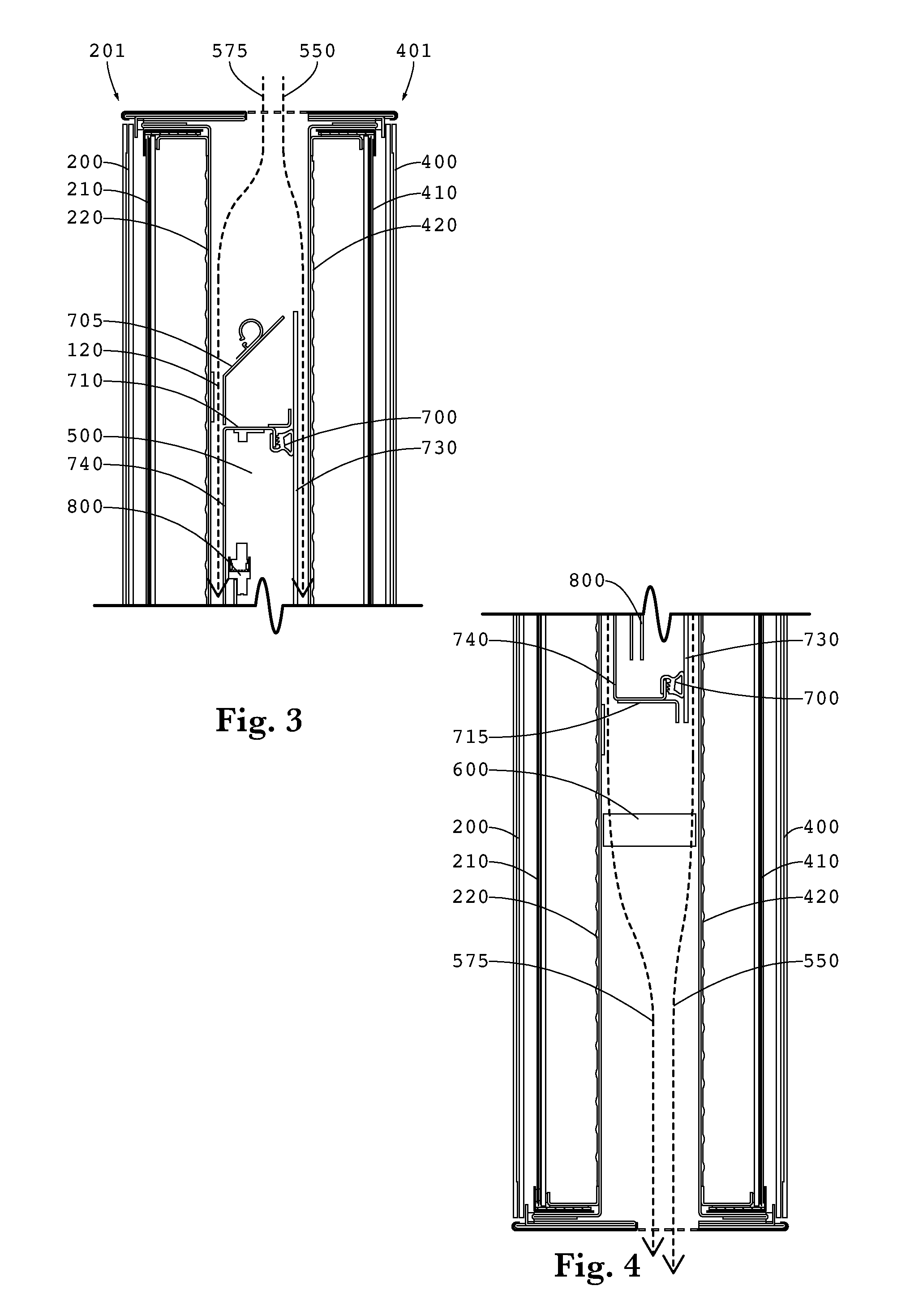
FIG. 2 is a section view taken along the section line A-A and showing Detail 3 and Detail 4 as well as vertical section line B-B.
FIG. 3 is a detailed section view showing Detail 3.
FIG. 4 is a detailed section view showing Detail 4.
FIG. 5 is a section view taken along the section line A-A and showing the second display assembly rotated away from the first display assembly and also showing Detail 6.
FIG. 6 is a detailed section view showing Detail 6.
FIG. 7 is a perspective view showing an alternate embodiment where the first display assembly is rotated away from the second display assembly.
FIG. 8 is a perspective view taken along the line B-B and indicating Detail 9.
FIG. 9 is a detailed perspective view of Detail 9 showing the post.
FIG. 10 is a detailed perspective view of the corresponding hook on the second display assembly.
DETAILED DESCRIPTION
The invention is described more fully hereinafter with reference to the accompanying drawings, in which exemplary embodiments of the invention are shown. This invention may, however, be embodied in many different forms and should not be construed as limited to the exemplary embodiments set forth herein. Rather, these embodiments are provided so that this disclosure will be thorough and complete, and will fully convey the scope of the invention to those skilled in the art. In the drawings, the size and relative sizes of layers and regions may be exaggerated for clarity.
The terminology used herein is for the purpose of describing particular embodiments only and is not intended to be limiting of the invention. As used herein, the singular forms "a", "an" and "the" are intended to include the plural forms as well, unless the context clearly indicates otherwise. It will be further understood that the terms "comprises" and/or "comprising," when used in this specification, specify the presence of stated features, integers, steps, operations, elements, and/or components, but do not preclude the presence or addition of one or more other features, integers, steps, operations, elements, components, and/or groups thereof.
Embodiments of the invention are described herein with reference to illustrations that are schematic illustrations of idealized embodiments (and intermediate structures) of the invention. As such, variations from the shapes of the illustrations as a result, for example, of manufacturing techniques and/or tolerances, are to be expected. Thus, embodiments of the invention should not be construed as limited to the particular shapes of regions illustrated herein but are to include deviations in shapes that result, for example, from manufacturing.
Unless otherwise defined, all terms (including technical and scientific terms) used herein have the same meaning as commonly understood by one of ordinary skill in the art to which this invention belongs. It will be further understood that terms, such as those defined in commonly used dictionaries, should be interpreted as having a meaning that is consistent with their meaning in the context of the relevant art and will not be interpreted in an idealized or overly formal sense unless expressly so defined herein.
FIG. 1 is a front planar view of an exemplary back to back display assembly 1000 showing the vertical section line A-A. In this orientation the first display assembly 201 is the only display that is viewable.
FIG. 2 is a section view taken along the section line A-A and showing Detail 3 and Detail 4 as well as vertical section line B-B. A first display assembly 201 is positioned back-to-back with a second display assembly 401. In an exemplary embodiment, the two display assemblies 201 and 401 are substantially parallel with the rear surfaces of each display assembly facing each other. The first display assembly 201 preferably contains a front cover glass 200, LCD panel 210, and LED backlight 220. The second display assembly 401 preferably contains a front cover glass 400, LCD panel 410, and LED backlight 420. Although shown and described herein with LED backlight LCD technology, the exemplary embodiments herein can be practiced with any form of flat panel display, including but not limited to OLED, LED, plasma, and any luminescent polymers. In these embodiments, the rear surface of the LED backlight would simply be the rear surface of an OLED, LED, plasma, or a luminescent polymer display.
An enclosed plenum 500 preferably contains the electronics 800 for operating the two displays and is positioned between the two display assemblies 201 and 401. A fan 600 is also positioned between the two display assemblies 201 and 401 and is positioned to draw surrounding external air through the assembly 1000, preferably without permitting any of the external air to enter the plenum 500. Although only a single fan 600 is shown, multiple fans may be used in some embodiments, either in the same or a different location than the fan 600 which is shown. Further, while the fan 600 is shown pulling the external air through the assembly 1000, it could also be positioned to push the external air through the assembly 10000. Still further, although shown at the bottom of the display assembly 1000, it could instead be placed at the top.
FIG. 3 is a detailed section view showing Detail 3. FIG. 4 is a detailed section view showing Detail 4. The plenum 500 is preferably enclosed by a first wall 740 which faces the first display assembly 201, a second wall 730 which faces the second display assembly 401, a top wall 710, bottom wall 715, and a pair of opposing sidewalls 701 (not shown in this view). In this embodiment, the first wall 740, a top wall 710, bottom wall 715, and opposing sidewalls 701 are fixed relative to one another while the second wall 730 is movable relative to these pieces. While this is shown here, other embodiments could fix the second wall 730 relative to the top wall 710, bottom wall 715, and opposing sidewalls 701 while the first wall 740 is movable relative to these pieces. Preferably, the walls 740, 710, 715, 730, and the sidewalls 701 are metallic and preferably aluminum.
The second wall 730 seals the plenum 500 when the gasket 700 is compressed between the second wall 730 and the top wall 710, bottom wall 715, and opposing sidewalls 701. The electronics 800 contained within the plenum are protected from the external air flows 575 and 550 and any possible contaminates, particulate, or water vapor that may be present. The electronics can include, but are not limited to: power supplies, microprocessors, printed circuit boards, electronic memory, transmitting/receiving devices, and video players. Preferably the electronics 800 are also in thermal communication (preferably conductive) with either the first wall 740, second wall 730, or both. In this way, heat from the electronics 800 can be transferred to the first wall 740 to be removed by first external air flow 575 or the second wall 730 to be removed by the second external air flow 550.
A first gap is preferably defined between the first display assembly 201 and the first wall 740 of the plenum 500. A second gap is defined between the second display assembly 401 and the second wall 730 of the plenum 500. In this particular embodiment where an LCD with an LED backlight is being used, the first gap is between the rear surface of the LED backlight 220 and the first wall 740 and the second gap is between the rear surface of the LED backlight 420 and the second wall 730. A first external airflow 575 is ingested into the housing through an inlet aperture, forced through the first gap, and then exhausted out of the housing through an exhaust aperture. A second external airflow 550 is ingested into the housing through an inlet aperture, forced through the second gap, and then exhausted out of the housing through an exhaust aperture. In this way, airflow 575 can remove heat simultaneously from the LED backlight 220 and the first wall 740 while airflow 550 can remove heat simultaneously from the LED backlight 420 and the second wall 730.
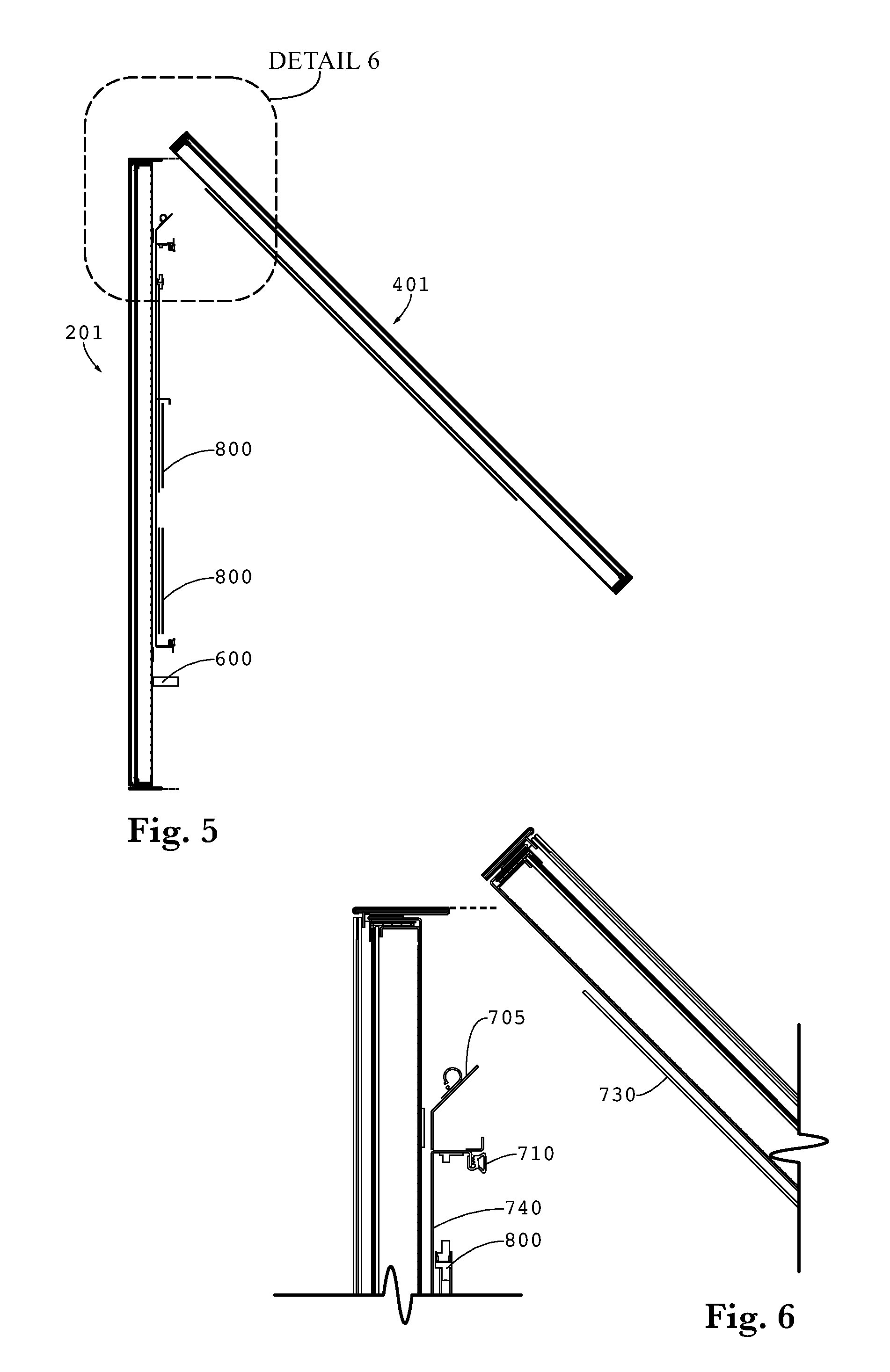
FIG. 5 is a section view taken along the section line A-A and showing the second display assembly rotated away from the first display assembly and also showing Detail 6. In this embodiment, the first display assembly 201 remains fixed while the second display assembly 401 is permitted to move or rotate away from the first display assembly 201, providing access to the interior of the plenum and the electronics 800 inside.
FIG. 6 is a detailed section view showing Detail 6. Here, a sloped rain catcher 705 is placed below the inlet aperture and above the plenum so as to collect any condensation and direct it down the first gap. This figure also shows the movement of the second wall 730 along with the second display assembly 401, as they move away from the first wall 740, a top wall 710, bottom wall 715, and opposing sidewalls 701 to provide access to the interior of the plenum.
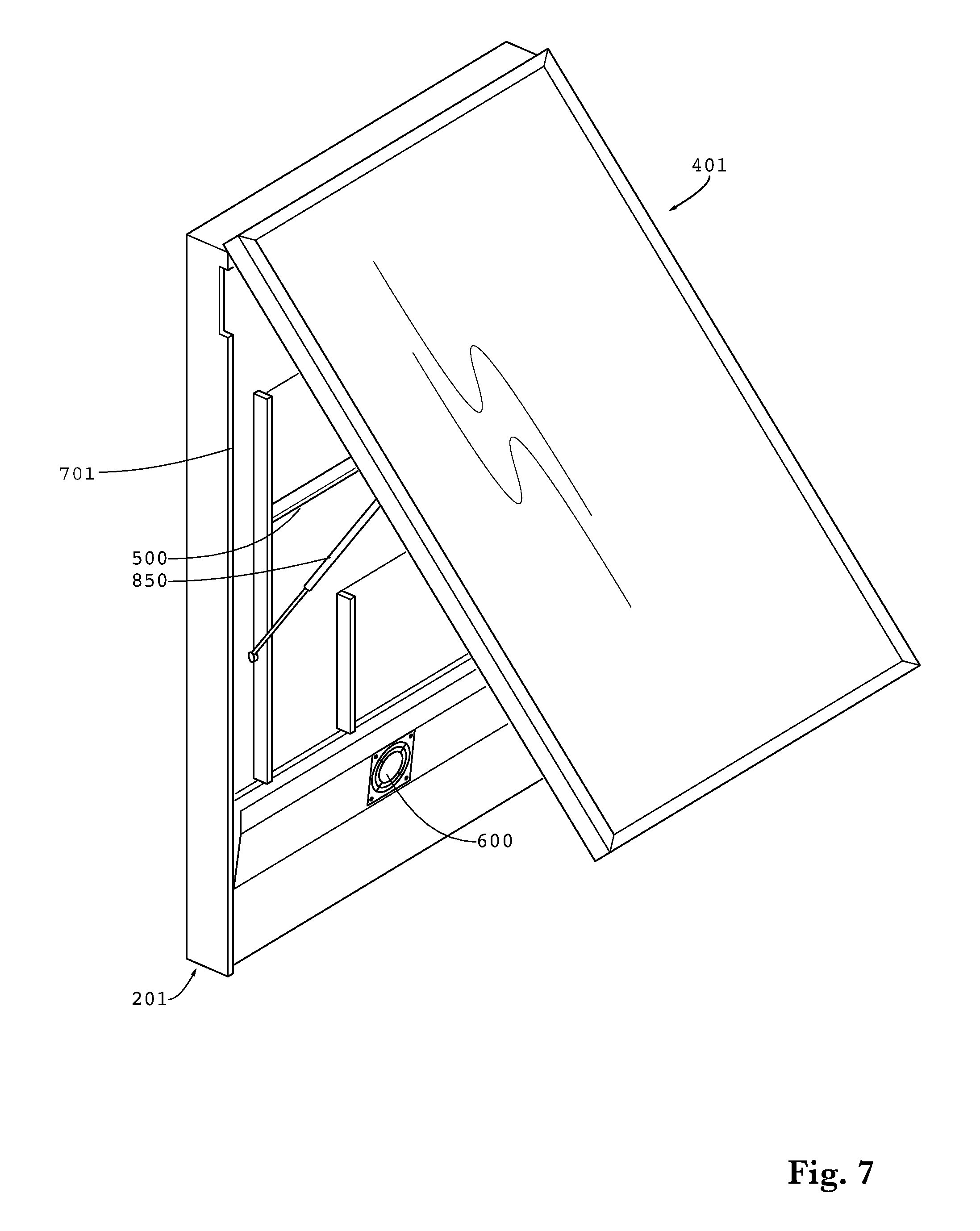
FIG. 7 is a perspective view showing an alternate embodiment where the first display assembly 201 is rotated away from the second display assembly 401 (which remains fixed). Here, a pair of gas springs 850 are used to help rotate the display assembly 201 and hold it in an open position while the interior of the plenum 500 is being serviced.
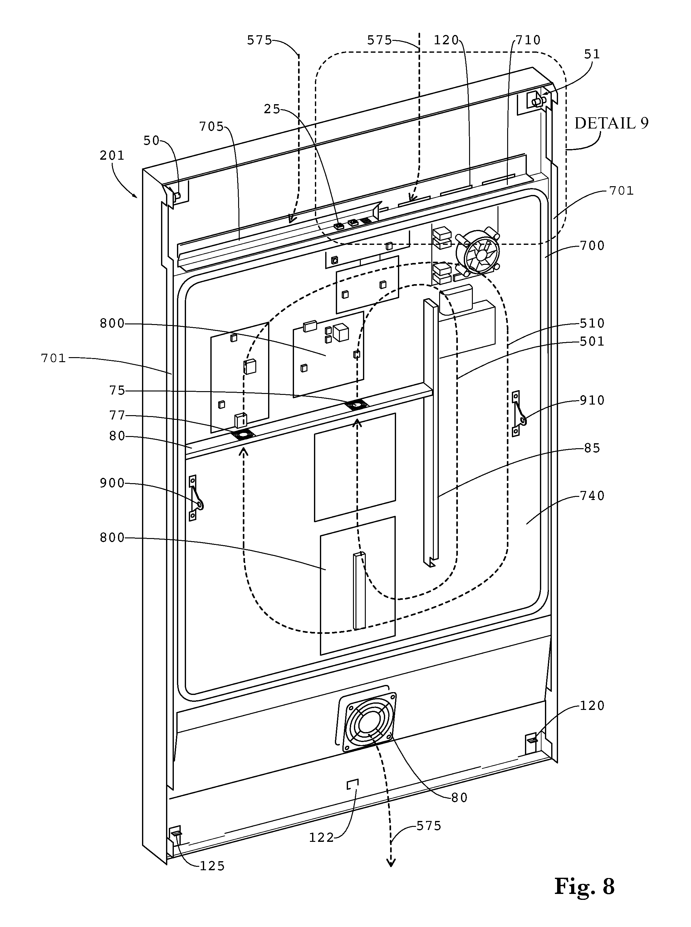
FIG. 8 is a perspective view taken along the line B-B and indicating Detail 9. In this embodiment, the first wall 740 is used to mount the various electronics 800, although these could instead be mounted to the rear wall 730. In some embodiments, electronics 800 may be mounted to both the first wall 740 and the second wall 730. The top wall 710 substantially prohibits airflow from entering the plenum. An opening 120 is preferably placed on or near the top wall 710 to allow airflow 575 to enter the gap defined by the opening of the space between the first wall 740 and the rear of the LED backlight 220. In a similar manner, another opening (not shown here) is preferably provided on or near the top wall 710 to allow airflow 550 to enter the gap defined by the opening of the space between the second wall 730 and the rear of the LED backlight 420.
A gasket 700 is preferably positioned around the perimeter of the first wall 740 so that the gasket 700 is compressed between the plenum walls (top wall 710, bottom wall 715, and pair of opposing sidewalls) and the second wall 730 when the unit is closed. Preferably, a pair of dividing walls 80/85 are used to define a loop around the plenum 500 which may contain circulating gas and passes through only one of the dividing walls (here 80). Generally speaking, the dividing walls 80/85 should connect between the first wall 740 and second wall 730 of the plenum. In an exemplary embodiment, dividing wall 80 is perpendicular to dividing wall 85. Even more preferably, dividing wall 80 is arranged horizontally and contains the fan(s) while dividing wall 85 is connected to the end of dividing wall 80 but is arranged vertically and does not contain a fan. Although fans are only shown within the dividing wall 80, they could instead be placed within the dividing wall 85, or only within the dividing wall 85 with no fans placed within dividing wall 80. For exemplary airflow, it has been discovered that placing the first fan 75 near the center of the display assembly and the second fan 77 near the perimeter of the display assembly, causes a pair of circulating gas loops 501 and 510 respectfully.
A plurality of input/output electrical connections 25 are preferably placed at the top of the display assembly 201 and underneath a sloped rain catcher 705. Also, a pair of mounting pins 50 and 51 are arranged at the top of the display assembly 201. A plurality of latches 120, 122, 125 are preferably arranged at the bottom of the display assembly 201, although shown with three latches embodiments can be practiced with one or two latches only. Also shown in this figure are the attachment brackets 900 and 910 for gas springs 850 or other supporting resistive elements.
FIG. 9 is a detailed perspective view of Detail 9 showing the post. Here, the details of the post 51 may be observed. In this embodiment, a cylinder travels horizontally and is divided by two locating walls 53 (closest to the perimeter of the display assembly 201) and 54 (closest to the center of the display assembly 201). The cylinder can then be identified by the mounting portion 55 (located between walls 53/54) and the interior portion 52 (starting at the wall 54 and travelling towards the center of the module 500).
FIG. 10 is a detailed perspective view of the corresponding hook 450 on the second display assembly 401. A pair of mounting hooks 450 are preferably placed at the top of the second display assembly 401 and correspond to the mounting posts 50 and 51 respectively. Preferably, the hook 450 would wrap around the circumference of the mounting portions 55, where the hook 300 is stabilized between the walls 54 and 53.
Having shown and described a preferred embodiment of the invention, those skilled in the art will realize that many variations and modifications may be made to affect the described invention and still be within the scope of the claimed invention. Additionally, many of the elements indicated above may be altered or replaced by different elements which will provide the same result and fall within the spirit of the claimed invention. It is the intention, therefore, to limit the invention only as indicated by the scope of the claims.
* * * * *
D00000
D00001
D00002
D00003
D00004
D00005
D00006
XML
uspto.report is an independent third-party trademark research tool that is not affiliated, endorsed, or sponsored by the United States Patent and Trademark Office (USPTO) or any other governmental organization. The information provided by uspto.report is based on publicly available data at the time of writing and is intended for informational purposes only.
While we strive to provide accurate and up-to-date information, we do not guarantee the accuracy, completeness, reliability, or suitability of the information displayed on this site. The use of this site is at your own risk. Any reliance you place on such information is therefore strictly at your own risk.
All official trademark data, including owner information, should be verified by visiting the official USPTO website at www.uspto.gov. This site is not intended to replace professional legal advice and should not be used as a substitute for consulting with a legal professional who is knowledgeable about trademark law.