Charging pack with flexible attachment members
Balmer Ja
U.S. patent number 10,193,365 [Application Number 15/353,573] was granted by the patent office on 2019-01-29 for charging pack with flexible attachment members. This patent grant is currently assigned to Vitec Holdings Italia SRL. The grantee listed for this patent is Daymen US, Inc.. Invention is credited to Noah Balmer.


View All Diagrams
| United States Patent | 10,193,365 |
| Balmer | January 29, 2019 |
Charging pack with flexible attachment members
Abstract
A charging pack for an electronic device which includes flexible members adapted to snugly attach the charging pack to an electronic device such as a cellular telephone. The flexible members may stretch to capture the corners of the cellular telephone. The flexible members may reside along a back surface of the charging pack in a stowed configuration. The flexible members may stretch over the corners of the charging pack main body to provide protection to the charging pack.
| Inventors: | Balmer; Noah (Santa Rosa, CA) | ||||||||||
|---|---|---|---|---|---|---|---|---|---|---|---|
| Applicant: |
|
||||||||||
| Assignee: | Vitec Holdings Italia SRL
(Cassola, IT) |
||||||||||
| Family ID: | 59897151 | ||||||||||
| Appl. No.: | 15/353,573 | ||||||||||
| Filed: | November 16, 2016 |
Prior Publication Data
| Document Identifier | Publication Date | |
|---|---|---|
| US 20170279289 A1 | Sep 28, 2017 | |
Related U.S. Patent Documents
| Application Number | Filing Date | Patent Number | Issue Date | ||
|---|---|---|---|---|---|
| 62255534 | Nov 16, 2015 | ||||
| Current U.S. Class: | 1/1 |
| Current CPC Class: | G06F 1/1632 (20130101); H01M 10/46 (20130101); H02J 7/342 (20200101); H01M 2/20 (20130101); H01M 10/425 (20130101); H02J 7/0045 (20130101); Y02E 60/10 (20130101); H01M 2220/30 (20130101) |
| Current International Class: | H02J 7/00 (20060101); H01M 10/42 (20060101); H01M 10/46 (20060101); G06F 1/16 (20060101); H01M 2/20 (20060101) |
| Field of Search: | ;320/110 |
References Cited [Referenced By]
U.S. Patent Documents
| 2004/0085043 | May 2004 | Germagian |
| 2004/0196001 | October 2004 | Kwon |
| 2006/0125445 | June 2006 | Cao |
| 2011/0309794 | December 2011 | Budziszek |
| 2014/0168866 | June 2014 | Armstrong |
| 2014/0191033 | July 2014 | Wojcik |
| 2015/0093623 | April 2015 | Huang |
| 2016/0261133 | September 2016 | Wang |
Attorney, Agent or Firm: Guth; Michael A.
Parent Case Text
CROSS-REFERENCE TO RELATED APPLICATIONS
This application claims priority to U.S. Provisional Application No. 62/255,534 to Balmer, filed Nov. 16, 2015.
Claims
What is claimed is:
1. A charging pack for an electronic device, said charging pack comprising: a main body, wherein said main body is rectangular, said main body having a front and a back; a battery inside said main body adapted to deliver power to an electronic device; and a flexible element, said flexible element attached to said body, said flexible element adapted to attach the charging pack to an electronic device, said flexible element comprising: a central attachment portion affixed to said main body; a first outer band portion adapted to capture a first corner of an electronic device, said first outer band portion comprising a first end and a second end, wherein said first outer band portion is coupled to said central attachment portion at said first end and said second end of said first band portion; a second outer band portion adapted to capture a second corner of an electronic device, said second outer band portion comprising a first end and a second end, wherein said second outer band portion is coupled to said central attachment portion at said first end and said second end of said second band portion; a third outer band portion adapted to capture a third corner of an electronic device, said third outer band portion comprising a first end and a second end, wherein said third outer band portion is coupled to said central attachment portion at said first end and said second end of said third band portion; and a fourth outer band portion adapted to capture a fourth corner of an electronic device, said fourth outer band portion comprising a first end and a second end, wherein said fourth outer band portion is coupled to said central attachment portion at said first end and said second end of said fourth band portion; wherein said flexible element resides along the back of said main body while in a stowed configuration, and wherein said first, second, third, and fourth outer band portions of said flexible element are stretched over the corners of said rectangular main body while in a second configuration.
2. The charging pack of claim 1 further comprising an outlet cable coupled to said main body.
3. The charging pack of claim 1 wherein said main body comprises an inlet connector adapted to receive power input for charging said battery.
4. The charging pack of claim 1 wherein said main body comprises an inlet connector adapted to receive power input for charging said battery.
Description
BACKGROUND
Field of the Invention
The claimed relates to a charging pack for an electronic device.
Description of Related Art
SUMMARY
A charging pack for an electronic device which includes flexible members adapted to snugly attach the charging pack to an electronic device such as a cellular telephone. The flexible members may stretch to capture the corners of the cellular telephone. The flexible members may reside along a back surface of the charging pack in a stowed configuration. The flexible members may stretch over the corners of the charging pack main body to provide protection to the charging pack.
BRIEF DESCRIPTION OF THE DRAWINGS
FIG. 1 is a front view of a charging pack for an electronic device in a first, stowed, configuration.
FIG. 2 is a back view of a charging pack for an electronic device in the first configuration.
FIG. 3 is a top view of a charging pack for an electronic device in the first configuration.
FIG. 4 is a bottom view of a charging pack for an electronic device in the first configuration.
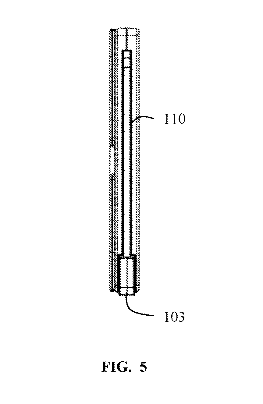
FIG. 5 is a left side view of a charging pack for an electronic device in the first configuration.
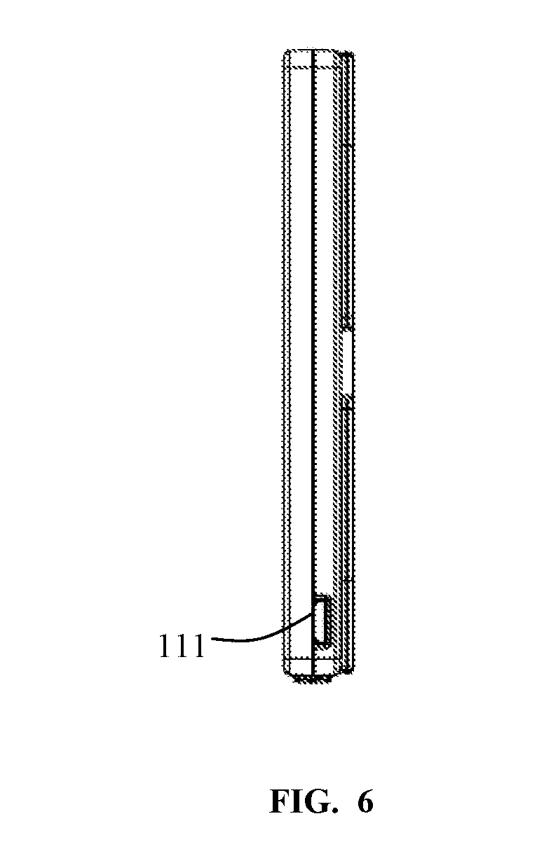
FIG. 6 is a right side view of a charging pack for an electronic device in the first configuration.
FIG. 7 is a rear perspective view of a charging pack for an electronic device in the first configuration.
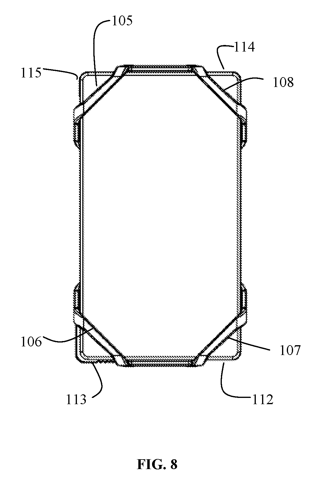
FIG. 8 is a front view of a charging pack for an electronic device in a second configuration with the flexible members pulled over the charging pack body.
FIG. 9 is a rear view of a charging pack for an electronic device in the second configuration.
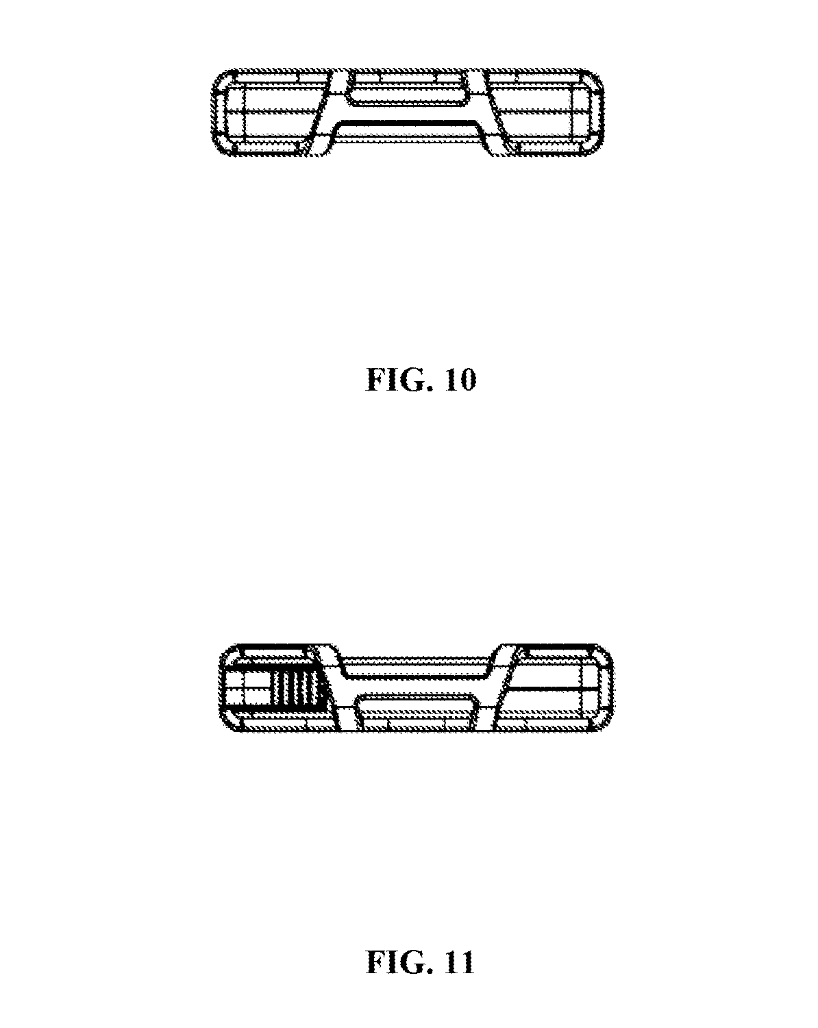
FIG. 10 is a top view of a charging pack for an electronic device in the second configuration.
FIG. 11 is a bottom view of a charging pack for an electronic device in the second configuration.
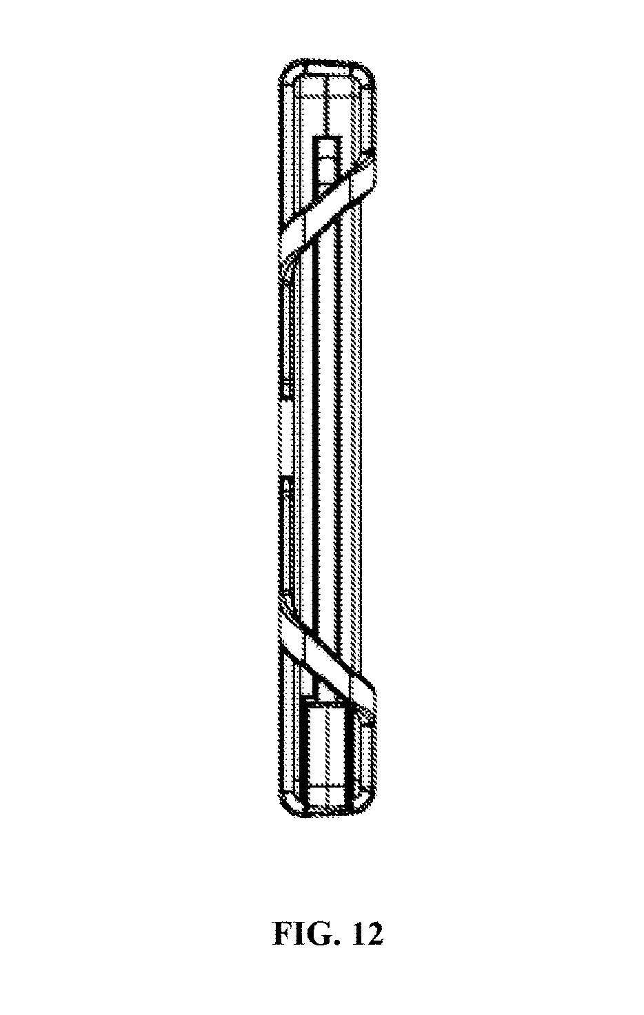
FIG. 12 is a left side view of a charging pack for an electronic device in the second configuration.
FIG. 13 is a right side view of a charging pack for an electronic device in the second configuration.
FIG. 14 is a lower front perspective view of a charging pack for an electronic device in the second configuration.
FIG. 15 is a lower rear perspective view of a charging pack for an electronic device in the second configuration.
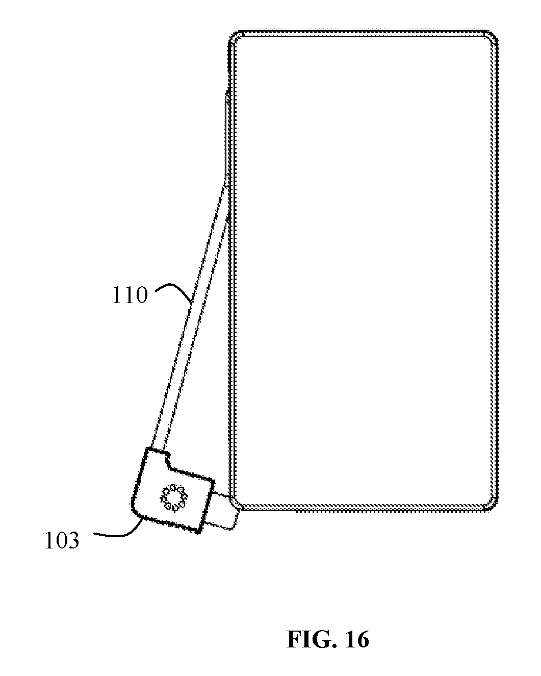
FIG. 16 is a front view of a charging pack for an electronic device in a third configuration with the power cord partially deployed.
FIG. 17 is a rear view of a charging pack for an electronic device in the third configuration.
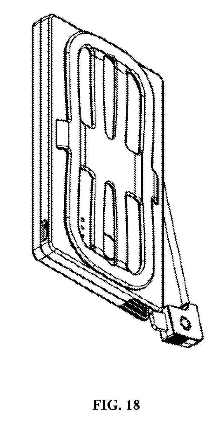
FIG. 18 is a lower rear perspective view of a charging pack for an electronic device in the third configuration.
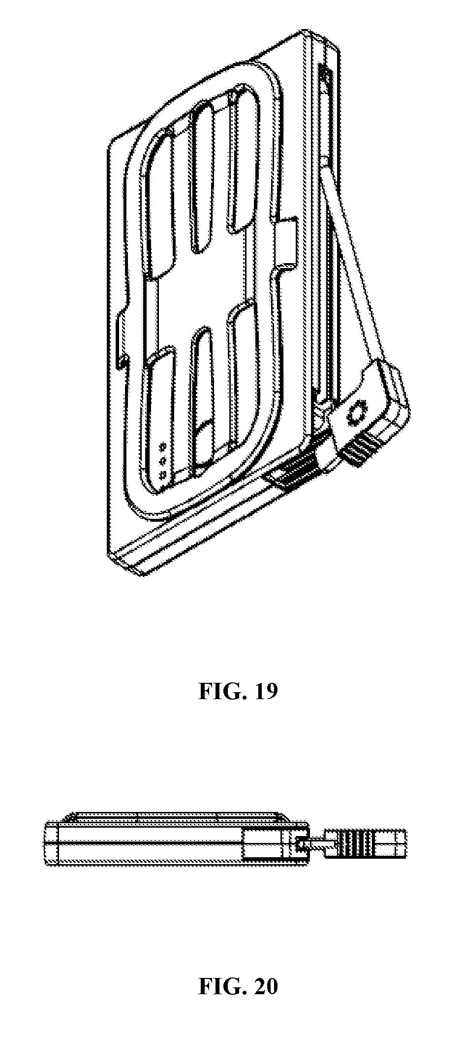
FIG. 19 is a lower side perspective view of a charging pack for an electronic device in the third configuration.
FIG. 20 is a bottom view of a charging pack for an electronic device in the third configuration.
FIG. 21 is a front view of a charging pack for an electronic device in a fourth configuration attached to a cellular telephone.
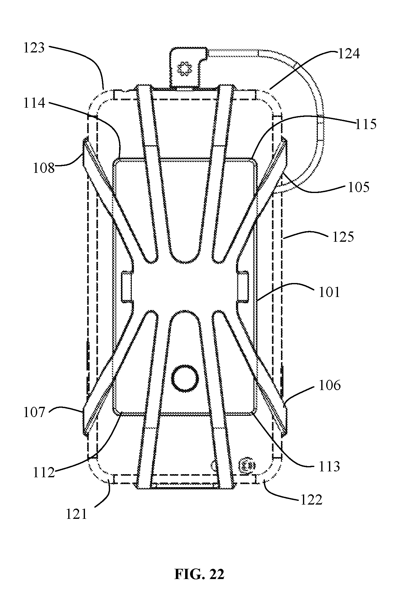
FIG. 22 is a rear view of a charging pack for an electronic device in the fourth configuration.
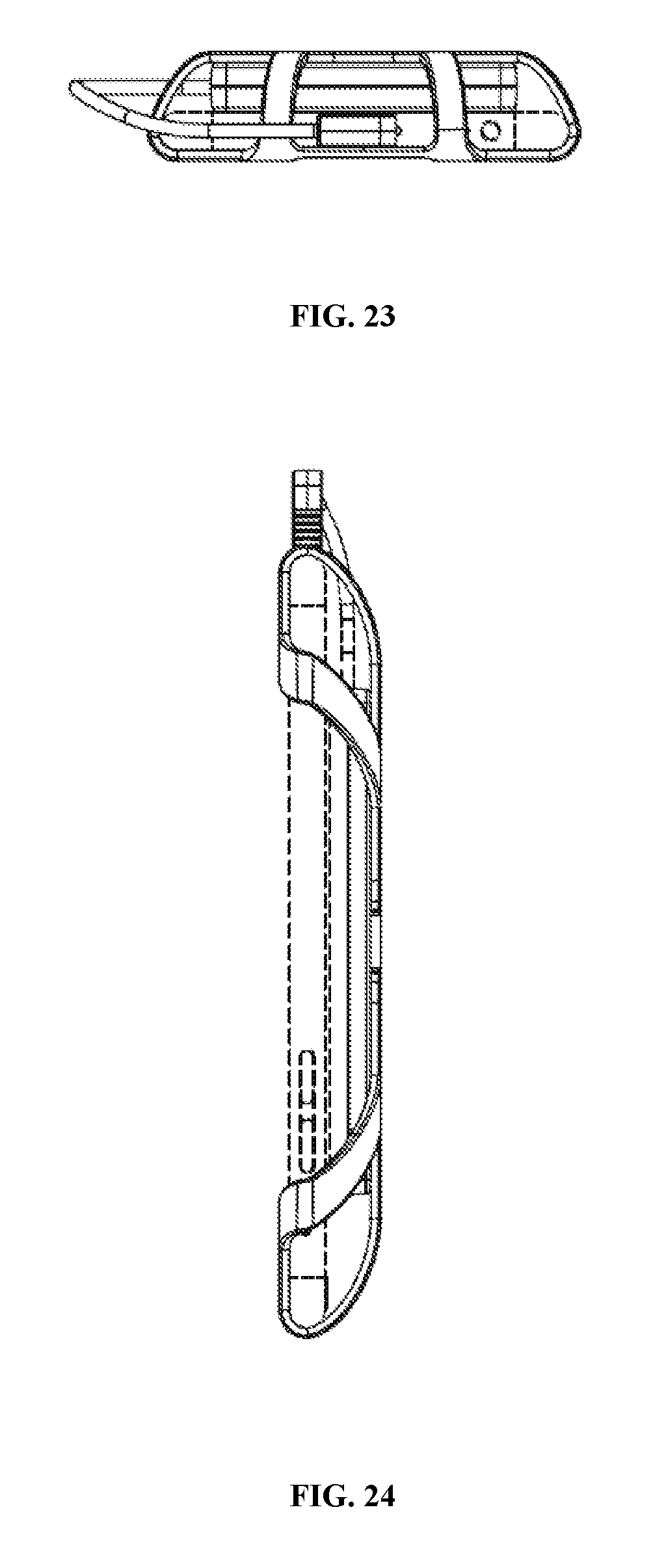
FIG. 23 is a top view of a charging pack for an electronic device in the fourth configuration.
FIG. 24 is a right side view of a charging pack for an electronic device in the fourth configuration.
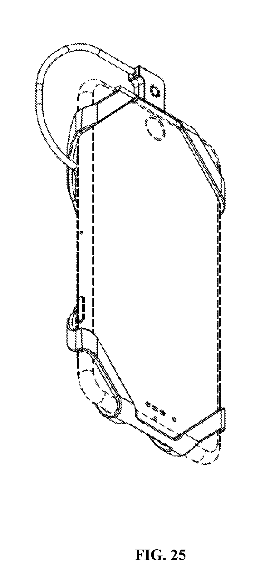
FIG. 25 is a front lower perspective view of a charging pack for an electronic device in the fourth configuration.
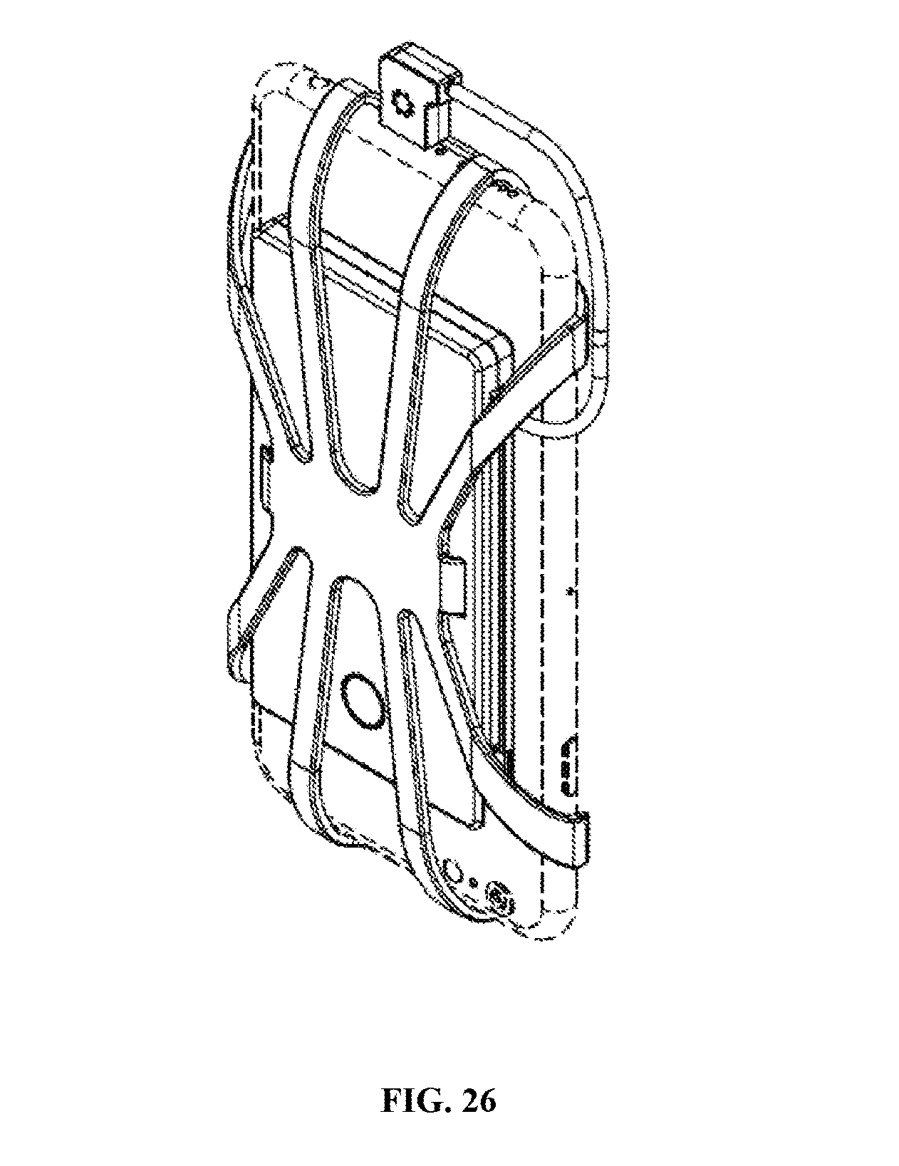
FIG. 26 is a rear side perspective view of a charging pack for an electronic device in the fourth configuration.
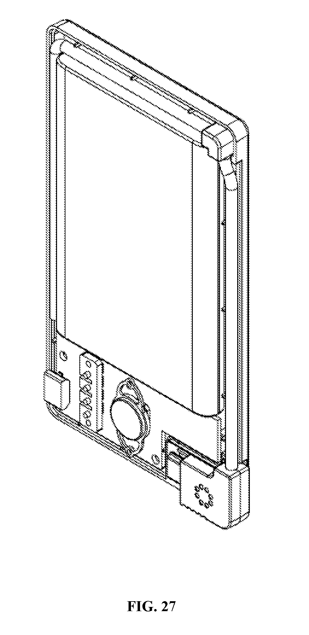
FIG. 27 is a partial cutaway view of a charging pack for an electronic device.
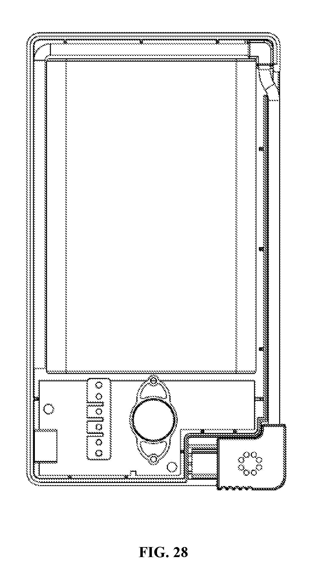
FIG. 28 is a partial cutaway view of a charging pack for an electronic device.
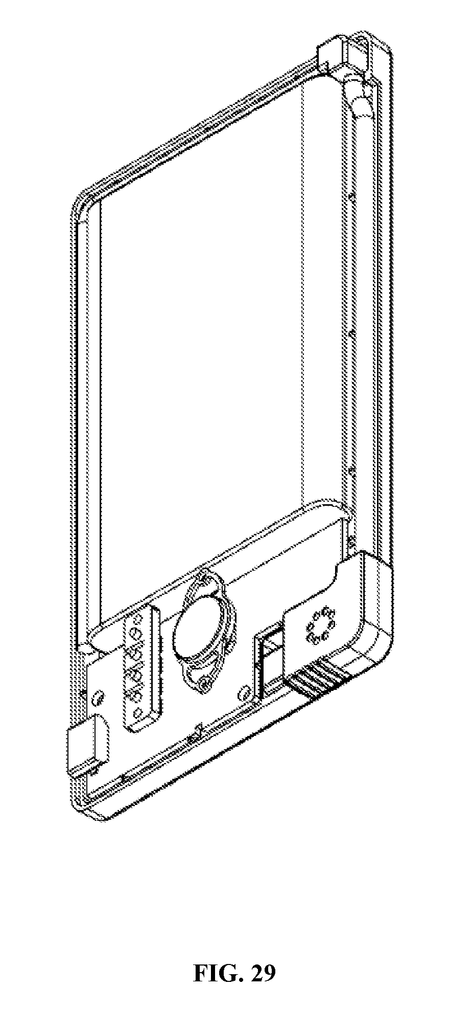
FIG. 29 is a partial cutaway view of a charging pack for an electronic device.
DETAILED DESCRIPTION
FIGS. 1-7 illustrate an embodiment of a charging pack for an electronic device 101 in a first configuration. In some embodiments, the main body 102 of the charging pack 101 is substantially rectangular. In an exemplary embodiment, the main body 102 is 103.6 mm.times.58 mm.times.9.4 mm. On a rear surface of the main body 102 resides a flexible member 104. The flexible member 104 is affixed to the rear surface of the main body 102 at an attachment portion 149 of the flexible member 104. In an exemplary embodiment, the flexible member 104 is silicone and has a dimension, while not extended, of 102.6 mm.times.44 mm.times.2 mm. The silicone flexible member may be sized and otherwise specified such that the flexible member is able to stretch over, but still snugly hold, electronic devices of varying sizes. In some aspects, the flexible member may extend through slots or holes in the main body to facilitate attachment to the main body. In some aspects, the flexible member may be bonded to the main body.
The charging pack 101 is adapted to have a variety of configurations. In a first, stowed, not extended, configuration, the flexible member 104 resides along the back of the main body 102. In another configuration, as seen in FIGS. 8-15, portions of the flexible members are stretched over the corners of the main body of the charging pack. In this configuration, the resilient silicone resides snugly over the charging pack main body affording impact protection, while also residing tightly enough over the main body that the stretched flexible member portions can remain in place over the corners of the main body as the user inserts and removes the unit from a pants pocket, for example. In yet another configuration, as seen in FIGS. 21-26, portions of the flexible member are further extended to tightly hold the charging pack onto and against an electronic device such as a cellular telephone. As further described below, in this configuration a power cord from the charging pack may be plugged into the electronic device, allowing energy flow from a battery or batteries within the charging pack into the electronic device.
FIGS. 2 and 7 best illustrate details of flexible member 104 in an exemplary embodiment. The flexible member 104 is attached to the main body of the charging pack at an attachment portion 149. The flexible member 104 has a plurality of elements which allow for stretching of the elements and attaching to electronic devices. An upper right outer band 105 and an upper right inner band 109 allow for stretching around an adjacent corner, whether of the charging pack itself, or of another device. An upper left outer band 108 an upper left inner band 110 also allow for stretching around an adjacent corner of a device. An upper middle band 139 joins the upper right and left areas. A lower right outer band 106 and a lower right inner band 112 allow for stretching around an adjacent corner, whether of the charging pack itself, or of another device. A lower left outer band 107 a lower left inner band 107 also allow for stretching around an adjacent corner of a device. A lower middle band 140 joins the lower right and left areas.
A deployable connector 103 resides within a recess in the main body of the charging pack. A power cable 110 routes power from within the charging pack to the connector 103. An electrical port 111 may be used to route power into the batteries within the charging pack in some embodiments.
Within the main body is a battery with a size, in an exemplary embodiment, of 103.6 mm.times.58 mm.times.9.4 mm. The battery capacity is 3200 mAh. Exemplary output voltage is DC 1.5V, 1.5 A max, 0.7 Wh.
FIGS. 8-15 illustrate another configuration of the charging pack wherein the flexible elements have been stretched to go over adjacent corners of the main body of the charging pack. This configuration allows for some impact protection for the charging pack, as well as putting the flexible elements into a taut configuration which keeps them in a low profile for insertion into a pocket, for example. The upper right outer band 105 may go around a first upper corner 115 of the charging pack, and the upper left outer band 108 may go around a second upper corner 114 of the charging pack. The lower right outer band 106 may go around a first lower corner 113 of the charging pack, and the lower left outer band 107 may go around a second lower corner 112 of the charging pack.
FIGS. 16-20 illustrate the deployable aspect of the connector 103 and its cable 110. When stowed, the connector 103 has a slight frictional fit to hold it into a mating recess in the main body of the charging pack. The cable 110 also resided within a mating recess within the main body of the charging pack.
FIGS. 21-26 illustrate the charging pack 101 in use with an electric device 125, which may be a smartphone, for example. This configuration allows for the very snug attachment of the charging pack to the electric device with the use of the extension of the flexible members. The upper right outer band 105 may go around a first upper corner 124 of the electronic device, and the upper left outer band 108 may go around a second upper corner 123 of the electronic device. The lower right outer band 106 may go around a first lower corner 122 of the electronic device, and the lower left outer band 107 may go around a second lower corner 121 of the electronic device. The mounting configuration allows for a surface of the main body of the charging pack to be in contact with the back surface of the electronic device, such as a smart phone. This mounting configuration thus allows for inductive charging of the electronic device by the charging pack should the charging pack be adapted to support that type of charging.
FIGS. 27-29 illustrate internal components of the charging pack. Within the charging pack are a battery and power control electronics adapted to allow for charging of the battery, and to allow for discharge of the battery through the use of an electronic device.
As evident from the above description, a wide variety of embodiments may be configured from the description given herein and additional advantages and modifications will readily occur to those skilled in the art. The invention in its broader aspects is, therefore, not limited to the specific details and illustrative examples shown and described. Accordingly, departures from such details may be made without departing from the spirit or scope of the applicant's general invention.
* * * * *
D00000
D00001
D00002
D00003
D00004
D00005
D00006
D00007
D00008
D00009
D00010
D00011
D00012

D00013

D00014
D00015

D00016
D00017
D00018

D00019
D00020
D00021
D00022
D00023
D00024
D00025
XML
uspto.report is an independent third-party trademark research tool that is not affiliated, endorsed, or sponsored by the United States Patent and Trademark Office (USPTO) or any other governmental organization. The information provided by uspto.report is based on publicly available data at the time of writing and is intended for informational purposes only.
While we strive to provide accurate and up-to-date information, we do not guarantee the accuracy, completeness, reliability, or suitability of the information displayed on this site. The use of this site is at your own risk. Any reliance you place on such information is therefore strictly at your own risk.
All official trademark data, including owner information, should be verified by visiting the official USPTO website at www.uspto.gov. This site is not intended to replace professional legal advice and should not be used as a substitute for consulting with a legal professional who is knowledgeable about trademark law.