Lens system, optical apparatus and manufacturing method
Take Ja
U.S. patent number 10,191,257 [Application Number 14/482,682] was granted by the patent office on 2019-01-29 for lens system, optical apparatus and manufacturing method. This patent grant is currently assigned to Nikon Corporation. The grantee listed for this patent is Nikon Corporation. Invention is credited to Toshinori Take.


View All Diagrams
| United States Patent | 10,191,257 |
| Take | January 29, 2019 |
Lens system, optical apparatus and manufacturing method
Abstract
A lens system having, in order from an object, at least a first lens group G1 having positive refractive power, and second to fourth lens groups G2 to G4, wherein the first lens group G1 includes a front portion lens group G1a, and a rear portion lens group G1b which is disposed to an image side of the front portion lens group G1a with an air distance therebetween, and performs focusing by shifting the rear portion lens group G1b in the optical axis direction, and the fourth lens group G4 includes, in order from the object, a negative lens and a positive lens (cemented negative lens L41), a negative lens L42, and an aperture stop S, and is fixed in the optical axis direction with respect to an image plane I upon zooming from a wide angle end state to a telephoto end state.
| Inventors: | Take; Toshinori (Yokohama, JP) | ||||||||||
|---|---|---|---|---|---|---|---|---|---|---|---|
| Applicant: |
|
||||||||||
| Assignee: | Nikon Corporation (Tokyo,
JP) |
||||||||||
| Family ID: | 43219913 | ||||||||||
| Appl. No.: | 14/482,682 | ||||||||||
| Filed: | September 10, 2014 |
Prior Publication Data
| Document Identifier | Publication Date | |
|---|---|---|
| US 20150089793 A1 | Apr 2, 2015 | |
Related U.S. Patent Documents
| Application Number | Filing Date | Patent Number | Issue Date | ||
|---|---|---|---|---|---|
| 13875546 | May 2, 2013 | ||||
| 12788292 | May 26, 2010 | 8503097 | |||
Foreign Application Priority Data
| May 27, 2009 [JP] | 2009-127260 | |||
| May 27, 2009 [JP] | 2009-127261 | |||
| May 27, 2009 [JP] | 2009-127262 | |||
| May 27, 2009 [JP] | 2009-127263 | |||
| Current U.S. Class: | 1/1 |
| Current CPC Class: | G02B 15/167 (20130101); G02B 15/20 (20130101); G02B 15/163 (20130101); G02B 15/173 (20130101); G02B 27/646 (20130101); G02B 15/14 (20130101); Y10T 29/49004 (20150115); Y10T 29/49826 (20150115) |
| Current International Class: | G02B 15/163 (20060101); G02B 15/167 (20060101); G02B 15/173 (20060101); G02B 15/20 (20060101); G02B 27/64 (20060101); G02B 15/14 (20060101) |
| Field of Search: | ;359/683,684,685 |
References Cited [Referenced By]
U.S. Patent Documents
| 5272564 | December 1993 | Suzuki et al. |
| 5715088 | February 1998 | Kenzaburo |
| 6141156 | October 2000 | Aoki |
| 6147810 | November 2000 | Misaka |
| 7218457 | May 2007 | Sensui |
| 7224535 | May 2007 | Neil |
| 7505213 | March 2009 | Tsutsumi et al. |
| 8405915 | March 2013 | Hayakawa |
| 2003/0053210 | March 2003 | Shinohara |
| 2003/0103268 | June 2003 | Nishikawa et al. |
| 2005/0275949 | December 2005 | Fujimoto et al. |
| 2007/0229966 | October 2007 | Nakatani et al. |
| 2007/0229971 | October 2007 | Souma |
| 2008/0247049 | October 2008 | Inoko |
| 2008/0259454 | October 2008 | Nanba |
| 2008/0297901 | December 2008 | Shinichi |
| 2010/0214667 | August 2010 | Hayakawa |
| 61-270718 | Dec 1986 | JP | |||
| 04-001715 | Jan 1992 | JP | |||
| 05-048937 | Feb 1993 | JP | |||
| 06-130330 | May 1994 | JP | |||
| 07-294817 | Nov 1995 | JP | |||
| 08-062541 | Mar 1996 | JP | |||
| 08-136863 | May 1996 | JP | |||
| 10-282413 | Oct 1998 | JP | |||
| 11-44848 | Feb 1999 | JP | |||
| 11-142738 | May 1999 | JP | |||
| 11-223770 | Aug 1999 | JP | |||
| 11-258504 | Sep 1999 | JP | |||
| 2001-75008 | Mar 2001 | JP | |||
| 2002-296502 | Oct 2002 | JP | |||
| 2003-241096 | Aug 2003 | JP | |||
| 2003-241098 | Aug 2003 | JP | |||
| 2004-61679 | Feb 2004 | JP | |||
| 2004-109559 | Apr 2004 | JP | |||
| 2004-212612 | Jul 2004 | JP | |||
| 2005-284097 | Oct 2005 | JP | |||
| 2005-352057 | Dec 2005 | JP | |||
| 2007-003600 | Jan 2007 | JP | |||
| 2007-192858 | Aug 2007 | JP | |||
| 2007-219040 | Aug 2007 | JP | |||
| 2007-264174 | Oct 2007 | JP | |||
| 2007-279077 | Oct 2007 | JP | |||
| 2008-257005 | Oct 2008 | JP | |||
Other References
|
Office Action (Notification of Reasons of Rejection) dated Dec. 14, 2012, in Japanese Patent Application No. 2009-127260. cited by applicant . Office Action (Notification of Reasons of Rejection) dated Dec. 14, 2012, in Japanese Patent Application No. 2009-127261. cited by applicant . Office Action (Notification of Reasons of Rejection) dated Dec. 14, 2012, in Japanese Patent Application No. 2009-127263. cited by applicant. |
Primary Examiner: Wilkes; Zachary
Attorney, Agent or Firm: Shapiro, Gabor and Rosenberger, PLLC
Claims
What is claimed is:
1. A lens system comprising, in order from an object, an "a" lens group having positive refractive power, a "b" lens group having negative refractive power, and a "c" lens group having positive refractive power, an aperture stop being disposed between the "b" lens group and the "c" lens group, all or a part of the "b" lens group being shifted so as to have a component orthogonal to the optical axis, wherein the "b" lens group is fixed in an optical axis direction with respect to an image plane upon zooming from a wide angle end state to a telephoto end state, and wherein upon zooming from a wide angle end state to a telephoto end state, a distance between the "a" lens group and the "b" lens group varies and a distance between the "b" lens group and the "c" lens group varies, and the aperture stop is integrated with the "b" lens group, and further comprising a first lens group which is closest to the object and placed closer to the object than the "a", "b" and "c" lens groups, and is placed closest to the object among the lens groups of the lens system, the first lens group having positive refractive power, and a second lens group, which is the second lens group from the object side, has negative refractive power, and the following conditional expression is satisfied: 0.55<(-f2)/fc<1.00 (5) where f2 denotes a focal length of the second lens group, and fc denotes a focal length of the "c" lens group, wherein the first lens group includes a front portion lens group, and a rear portion lens group disposed to an image side of the front portion lens group with an air distance therebetween, and wherein the following conditional expression is satisfied: 1.30<ft/f1b<3.10 wherein ft denotes a focal length of the total lens system in the telephoto end state, and f1b denotes a focal length of the rear portion lens group of the first lens group.
2. The lens system according to claim 1, wherein the "b" lens group is a fourth lens group from the object side.
3. The lens system according to claim 1, wherein the following conditional expression is satisfied: 0.23<(-f2)/(-fb)<0.88 where f2 denotes a focal length of the second lens group, and fb denotes a focal length of the "b" lens group.
4. The lens system according to claim 1, wherein focusing can be performed by shifting only the rear portion lens group of the first lens group in the optical axis direction.
5. The lens system according to claim 1, wherein at least one of the rear portion lens group and the front portion lens group of the first lens group has positive refractive power.
6. The lens system according to claim 1, wherein the first lens group is fixed in the optical axis direction with respect to the image plane upon focusing on infinity in zooming from the wide angle end state to the telephoto end state.
7. The lens system according to claim 1, wherein the "a" lens group is a third lens group from the object side, the "b" lens group is a fourth lens group from the object side, the "c" lens group is a fifth lens group from the object side, and further comprising a sixth lens group from the object side having negative refractive power.
8. The lens system according to claim 1, wherein the following conditional expression is satisfied: 0.90<TL/f1b<2.48 where TL denotes a total length of the lens system in the telephoto end, and f1b denotes a focal length of the rear portion lens group of the first lens group.
9. An optical apparatus comprising a lens system for forming an image of an object on a predetermined image plane, the lens system being the lens system according to claim 1.
10. A manufacturing method for the lens system of claim 1 which comprises: assembling each lens of the lens system in a lens barrel.
11. A lens system according to claim 1, wherein a total focus length is larger than 300 mm.
12. A lens system according to claim 1, wherein the number of lenses of the "a" group is more than the number of lenses of the "c" group.
13. A lens system according to claim 1, wherein the second additional expression is modified to be: 1.50<ft/f1b<3.10.
14. A lens system according to claim 1, wherein the second additional expression is modified to be: 1.70<ft/f1b<3.10.
15. A lens system comprising, in order from an object, an "a" lens group having positive refractive power, a "b" lens group having negative refractive power, and a "c" lens group having positive refractive power, an aperture stop being disposed between the "b" lens group and the "c" lens group, all or a part of the "b" lens group being shifted so as to have a component orthogonal to the optical axis, wherein the "b" lens group is fixed in an optical axis direction with respect to an image plane upon zooming from a wide angle end state to a telephoto end state, and wherein upon zooming from a wide angle end state to a telephoto end state, a distance between the "a" lens group and the "b" lens group varies and a distance between the "b" lens group and the "c" lens group varies, and the aperture stop is integrated with the "b" lens group, and further comprising a first lens group which is closest to the object and placed closer to the object than the "a", "b" and "c" lens groups, and is placed closest to the object among the lens groups of the lens system, the first lens group having positive refractive power, and a second lens group, which is the second lens group from the object side, has negative refractive power, and the following conditional expression is satisfied: 0.55<(-f2)/fc<1.00 (5) where f2 denotes a focal length of the second lens group, and fc denotes a focal length of the "c" lens group, wherein the first lens group includes a front portion lens group, and a rear portion lens group disposed to an image side of the front portion lens group with an air distance therebetween, and wherein focusing can be performed by shifting only the rear portion lens group of the first lens group in the optical axis direction.
16. A method of manufacturing a lens system comprising, in order from an object, an "a" lens group having positive refractive power, a "b" lens group having negative refractive power, and a "c" lens group having positive refractive power, an aperture stop being disposed between the "b" lens group and the "c" lens group, all or a part of the "b" lens group being shifted so as to have a component orthogonal to the optical axis, wherein the "b" lens group is fixed in an optical axis direction with respect to an image plane upon zooming from a wide angle end state to a telephoto end state, and wherein upon zooming from a wide angle end state to a telephoto end state, a distance between the "a" lens group and the "b" lens group varies and a distance between the "b" lens group and the "c" lens group varies, and the aperture stop is integrated with the "b" lens group, and further comprising a first lens group which is closest to the object and placed closer to the object than the "a", "b" and "c" lens groups, and is placed closest to the object among the lens groups of the lens system, the first lens group having positive refractive power, and a second lens group, which is the second lens group from the object side, has negative refractive power, and the following conditional expression is satisfied: 0.55<(-f2)/fc<1.00 (5) where f2 denotes a focal length of the second lens group, and fc denotes a focal length of the "c" lens group, wherein the first lens group includes a front portion lens group, and a rear portion lens group disposed to an image side of the front portion lens group with an air distance therebetween, wherein focusing can be performed by shifting only the rear portion lens group of the first lens group in the optical axis direction, the method comprising: assembling each lens of the lens system in a lens barrel.
Description
INCORPORATION BY REFERENCE
This invention claims the benefit of Japanese Patent Application Nos. 2009-127260, 2009-127261, 2009-127262 and 2009-127263 which are hereby incorporated by reference.
TECHNICAL FIELD AND BACKGROUND
The present invention relates to a lens system that is used for an optical apparatus such as a digital still camera.
As a focusing method for a high zoom ratio optical system, a front lens feed method for feeding a lens group disposed closest to the object (e.g. see Japanese Laid-Open Patent Publication No. H11-258504) and an internal focusing method (e.g. see Japanese Laid-Open Patent Publication No. 2004-212612) have been known.
However if focusing is attempted using the conventional front lens feed method, the support mechanism and driver mechanism of the focusing lens group tend to be large, since the large and heavy lens group that is disposed closest to the object is normally moved.
The total length of the lens system also tends to increase upon focusing on an object at close distance.
If the conventional internal focusing method is used, an advantage is that the support mechanism and drive mechanism of the focusing lens group can be compact, since the focusing lens group is a second or subsequent lens group, which is lighter than the first lens group disposed closest to the object. However in the case of the internal focusing method, the focusing mechanism tends to become complicated, since focusing cannot be performed on objects at a same photographic distance with a same feed amount throughout the entire zooming range from the wide angle end state to the telephoto end state.
Further, in order to prevent a photographic error due to an image blur caused by hand motion, it is desired that the above mentioned high zoom ratio zoom lens has an image blur correction function, which corrects an image blur on the image plane by setting all or a part of one lens group, out of the lens group constituting the lens system, as a shift lens group, and shifting the shift lens group so as to have a component approximately orthogonal to the optical axis, according to a value that is output by a detection system for detecting a blur of the lens system. Generally for a shift lens group, it is preferable to select a lens group located near a diaphragm where the abaxial flux of light passes near the optical axis upon zooming, so as to minimize the performance deterioration during lens shift.
Moreover many optical systems with high zoom ratios have a vibration proof function for correcting an image blur on an image plane by decentering all or a part of one lens group, out of the lens groups constituting the lens system, as a shift lens group, in order to prevent photographic errors due to an image blur caused by hand motion. However if a lens group which moves during zooming, is decentered for the purpose of vibration proofing as in the case of a conventional optical system, the optical performance may dramatically drop, which makes it impossible to obtain good images.
SUMMARY OF THE INVENTION
It is an object of the present invention to provide a lens system, an optical apparatus and a manufacturing method which can simultaneously implement a decrease in the total length of the lens system, and simplification of the focusing mechanism by appropriately setting the arrangement of the focusing lens group.
It is another object of the present invention to provide a lens system, an optical apparatus and a manufacturing method which can shift images, having an excellent image forming performance even if the shift lens group is shifted, by appropriately setting the arrangement of the shift lens group and aperture stop.
It is still another object of the present invention to provide a lens system, an optical apparatus and a manufacturing method which can minimize the influence of decentering so as to prevent the deterioration of performance.
A first aspect of the present invention is a lens system comprising, in order from an object, a first lens group having positive refractive power, and second to fourth lens groups, wherein the first lens group includes a front portion lens group, and a rear portion lens group disposed to an image side of the front portion lens group with an air distance therebetween, and performs focusing by shifting the rear portion lens group in an optical axis direction, and the fourth lens group includes, in order from the object, a negative lens, a positive lens, a negative lens and an aperture stop, and is fixed in the optical axis direction with respect to an image plane upon zooming from a wide angle end state to a telephoto end state.
In the first aspect of the present invention, it is preferable that the fourth lens group has, in order from the object, a cemented lens of a negative lens and a positive lens, a negative lens and an aperture stop.
In the first aspect of the present invention, it is preferable that the fourth lens group has, in order from the object, a cemented lens of a negative lens having a concave surface facing the object and a positive lens having a concave surface facing the image, a negative lens having a concave surface facing the object, and an aperture stop.
In the first aspect of the present invention, it is preferable that the fourth lens group has negative refractive power.
In the first aspect of the present invention, it is preferable that the conditional expression 1.30<ft/f1b<3.10 is satisfied, where ft denotes a focal length of the total lens system in the telephoto end state, and f1b denotes a focal length of the rear portion lens group of the first lens group.
In the first aspect of the present invention, it is preferable that the second lens group has negative refractive power.
In the first aspect of the present invention, it is preferable that the conditional expression 0.23<|f2/f4|<0.88 is satisfied, where f2 denotes a focal length of the second lens group and f4 denotes a focal length of the fourth lens group.
In the first aspect of the present invention, it is preferable that at least one of the front portion lens group and the rear portion lens group of the first lens group has positive refractive power.
In the first aspect of the present invention, it is preferable that the rear portion lens group of the first lens group has positive refractive power.
In the first aspect of the present invention, it is preferable that the conditional expression 0.90<TL/f1b<2.48 is satisfied, where TL denotes a total length of the lens system in the telephoto end state, and f1b denotes a focal length of the rear portion lens group of the first lens group.
In the first aspect of the present invention, it is preferable that the first lens group is fixed in the optical axis direction with respect to the image plane upon focusing on infinity in zooming from the wide angle end state to the telephoto end state.
In the first aspect of the present invention, it is preferable that the fourth lens group is fixed in the optical axis direction with respect to the image plane upon zooming from the wide angle end state to the telephoto end state.
In the first aspect of the present invention, it is preferable that the conditional expression 0.59<TL/ft<0.70 is satisfied, where TL denotes a total length of the lens system in the telephoto end state, and ft denotes a focal length of the total lens system in the telephoto end state.
In the first aspect of the present invention, it is preferable that the third lens group has positive refractive power.
In the first aspect of the present invention, it is preferable that the third lens group has at least one aspherical surface.
In the first aspect of the present invention, it is preferable that all or a part of the fourth lens group is shifted so as to have a component orthogonal to the optical axis.
It is preferable that the first aspect of the present invention has a fifth lens group and a sixth lens group which are disposed to an image side of the fourth lens group, wherein the first lens group has positive refractive power, the second lens group has negative refractive power, the third lens group has positive refractive power, the fourth lens group has negative refractive power, the fifth lens group has positive refractive power, and the sixth lens group has negative refractive power.
It is preferable that the first aspect of the present invention has a fifth lens group which is disposed to an image side of the fourth lens group, wherein the fifth lens group has positive refractive power.
In this case, it is preferable that the conditional expression 0.40<|f2/f5|<1.00 is satisfied, where f2 denotes a focal length of the second lens group, and f5 denotes a focal length of the fifth lens group.
It is also preferable that the fifth lens group, in order from the object, a positive lens component, a negative lens component, and a positive lens component, and the aperture stop is disposed to the object side of the fifth lens group.
It is also preferable that the fifth lens group further comprises, in order from the object, a cemented lens of a positive lens and a negative lens, and a positive lens.
It is also preferable that the fifth lens group has at least one aspherical surface.
It is also preferable that this lens system has a sixth lens group which is disposed to an image side of the fifth lens group, and the sixth lens group has negative refractive power.
An optical apparatus according to the present invention is an optical apparatus having a lens system for forming an image of an object on a predetermined image plane, wherein the lens system is the lens system according to the first aspect of the present invention.
A second aspect of the present invention is a lens system having, in order from an object, an "a" lens group having positive refractive power, a "b" lens group having negative refractive power, and a "c" lens group having positive refractive power, wherein an aperture stop is disposed between the "b" lens group and the "c" lens group, and all or a part of the "b" lens group is shifted so as to have a component orthogonal to the optical axis.
In the second aspect of the present invention, it is preferable that the "b" lens group is fixed in an optical axis direction with respect to an image plane upon zooming from a wide angle end state to a telephoto end state.
In the second aspect of the present invention, it is preferable that the aperture stop is integrated with the "b" lens group upon zooming from the wide angle end state to the telephoto end state.
In the second aspect of the present invention, it is preferable that the "b" lens group is a fourth lens group from the object side.
In the second aspect of the present invention, it is preferable that a second lens group, which is the second lens group from the object side, has negative refractive power, and the conditional expression 0.43<(-f2)/fc<1.00 is satisfied, where f2 denotes a focal length of the second lens group, and fc denotes a focal length of the "c" lens group.
In the second aspect of the present invention, it is preferable that the second lens group, which is the second lens group from the object side, has negative refractive power, and the conditional expression 0.23<(-f2)/(-fb)<0.88 is satisfied, where f2 denotes a focal length of the second lens group, and fb denotes a focal length of the "b" lens group.
In the second aspect of the present invention, it is preferable that a first lens group, which is disposed closest to the object, includes a front portion lens group, and a rear portion lens group disposed to an image side of the front portion lens group with an air distance therebetween.
In this case, it is preferable that the conditional expression 1.30<ft/f1b<3.10 is satisfied, where ft denotes a focal length of the total lens system in the telephoto end state, and f1b denotes a focal length of the rear portion lens group of the first lens group.
It is also preferable that focusing is performed by shifting the rear portion lens group of the first lens group in the optical axis direction.
An optical apparatus according to the present invention is an optical apparatus having a lens system for forming an image of an object on a predetermined image plane, wherein the lens system is the lens system according to the second aspect of the present invention.
A third aspect of the present invention is a lens system comprising, in order from an object, first to fifth lens groups, wherein the first lens group includes a front portion lens group, and a rear portion lens group disposed to an image side of the front portion lens group with an air distance therebetween, and performs focusing by shifting the rear portion lens group in an optical axis direction, and the fifth lens group includes, in order from the object, a positive lens component, a negative lens component and a positive lens component, and an aperture stop is disposed to the object side of the fifth lens group.
A fourth aspect of the present invention is a lens system comprising, in order from an object, first to fifth lens groups, wherein the first lens group is divided into at least two subgroups, a front portion lens group, which is a subgroup closest to the object our of the subgroups, has positive refractive power, and focusing is performed by shifting a rear portion lens group, which is a subgroup closest to an image out of the subgroups, in an optical axis direction, and the conditional expression 0.59<TL/ft<0.70 is satisfied, where TL denotes a total length of the lens system in a telephoto end state, and ft denotes a focal length of the total lens system in the telephoto end state.
Now configuration of a manufacturing method according to the present invention will be described.
A first manufacturing method of the present invention is a manufacturing method for a lens system which comprises, in order from an object, a first lens group having positive refractive power, and second to fourth lens groups, wherein operation is confirmed after each lens is assembled in a lens barrel so that the first lens group includes a front portion lens group, and a rear portion lens group disposed to an image side of the front portion lens group with an air distance therebetween, and performs focusing by shifting the rear portion lens group in an optical axis direction, and the fourth lens group includes, in order from the object, a negative lens, a positive lens, a negative lens and an aperture stop, and is fixed in the optical axis direction with respect to an image plane upon zooming from a wide angle end state to a telephoto end state.
In this manufacturing method, it is preferable that the fourth lens group further has, in order from the object, a cemented lens of a negative lens and a positive lens, a negative lens, and an aperture stop.
In the first manufacturing method, it is preferable that the conditional expression 1.30<ft/f1b<3.10 is satisfied, where ft denotes a focal length of the total lens system in the telephoto end state, and f1b denotes a focal length of the rear portion lens group of the first lens group.
In the first manufacturing method, it is preferable that the following conditional expression 0.23<|f2/f4|<0.88 is satisfied, where f2 denotes a focal length of the second lens group and f4 denotes a focal length of the fourth lens group.
A second manufacturing method of the present invention is a manufacturing method for a lens system which has, in order from an object, an "a" lens group having positive refractive power, a "b" lens group having negative refractive power, and a "c" lens group having positive refractive power, wherein operation is confirmed after each lens is assembled in a lens barrel so that an aperture stop is disposed between the "b" lens group and the "c" lens group, and all or a part of the "b" lens group is shifted so as to have a component orthogonal to the optical axis.
A third manufacturing method of the present invention is a manufacturing method for a lens system which comprises, in order from an object, first to fifth lens groups, wherein operation is confirmed after each lens is assembled in a lens barrel so that the first lens group includes a front portion lens group, and a rear portion lens group disposed to an image side of the front portion lens group with an air distance therebetween, and performs focusing by shifting the rear portion lens group in an optical axis direction, the fifth lens group includes, in order from the object, a positive lens component, a negative lens component, and a positive lens component, and an aperture stop is disposed to the object side of the fifth lens group.
A fourth manufacturing method of the present invention is a manufacturing method for a lens system which comprises, in order from an object, first to fifth lens groups, wherein operation is confirmed after each lens is assembled in a lens barrel so that the first lens group is divided into at least two subgroups, a front portion lens group, which is a subgroup closest to the object out of the subgroups, has positive refractive power, focusing is performed by shifting a rear portion lens group, which is a subgroup closest to an image out of the subgroups, in an optical axis direction, and the conditional expression 0.59<TL/ft>0.70 is satisfied, where TL denotes a total length of the lens system in a telephoto end state, and ft denotes a focal length of the total lens system in the telephoto end state.
Further scope of applicability of the present invention will become apparent from the detailed description given hereinafter. However, it should be understood that the detailed description and specific examples, while indicating preferred embodiments of the invention, are given by way of illustration only, since various changes and modifications within the spirit and scope of the invention will become apparent to those skilled in the art from this detailed description.
BRIEF DESCRIPTION OF THE DRAWINGS
The present invention will become more fully understood from the detailed description given herein below and the accompanying drawings which are given by way of illustration only and thus are not limitative of the present invention.
FIG. 1 is a diagram depicting an allocation of refractive power in a lens system according to each example of the present invention, and shifting state of each lens group upon changing of a focal distance state from the wide angle end state to the telephoto end state;
FIG. 2 is a diagram depicting a configuration of a lens system according to Example 1;
FIG. 3 are graphs showing various aberrations of the lens system according to Example 1 upon focusing on infinity, where FIG. 3A shows the wide angle end state, FIG. 3B shows the intermediate focal length state, and FIG. 3C shows the telephoto end state;
FIG. 4 are graphs showing coma aberrations of the lens system according to Example 1 in the lens shift state (0.4 mm) upon focusing on infinity, where FIG. 4A shows the wide angle end state, FIG. 4B shows the intermediate focal length state, and FIG. 4C shows the telephoto end state;
FIG. 5 are graphs showing various aberrations of the lens system according to Example 1 upon close distance focusing, where FIG. 5A shows the wide angle end state, FIG. 5B shows the intermediate focal length state, and FIG. 5C shows the telephoto end state;
FIG. 6 is a diagram depicting a configuration of a lens system according to Example 2;
FIG. 7 are graphs showing various aberrations of the lens system according to Example 2 upon focusing on infinity, where FIG. 7A shows the wide angle end state, FIG. 7B shows the intermediate focal length state, and FIG. 7C shows the telephoto end state;
FIG. 8 are graphs showing coma aberrations of the lens system according to Example 2 in the lens shift state (0.4 mm) upon focusing on infinity, where FIG. 8A shows the wide angle end state, FIG. 8B shows the intermediate focal length state, and FIG. 8C shows the telephoto end state;
FIG. 9 are graphs showing various aberrations of the lens system according to Example 2 upon close distance focusing, where
FIG. 9A shows the wide angle end state, FIG. 9B shows the intermediate focal length state, and FIG. 9C shows the telephoto end state;
FIG. 10 is a diagram depicting a configuration of a lens system according to Example 3;
FIGS. 11A to 11C are graphs showing various aberrations of the lens system according to Example 3 upon focusing on infinity, where FIG. 11A shows the wide angle end state, FIG. 11B shows the intermediate focal length state, and FIG. 11C shows the telephoto end state;
FIG. 12 are graphs showing various aberrations of the lens system according to Example 3 upon close distance focusing, where FIG. 12A shows the wide angle end state, FIG. 12B shows the intermediate focal length state, and FIG. 12C shows the telephoto end state;
FIG. 13 is a diagram depicting a configuration of a lens system according to Example 4;
FIG. 14 are graphs showing various aberrations of the lens system according to Example 4 upon focusing on infinity, where FIG. 14A shows the wide angle end state, FIG. 14B shows the intermediate focal length state, and FIG. 14C shows the telephoto end state;
FIG. 15 are graphs showing various aberrations of the lens system according to Example 4 upon close distance focusing, where FIG. 15A shows the wide angle end state, FIG. 15B shows the intermediate focal length state, and FIG. 15C shows the telephoto end state;
FIG. 16 is a diagram depicting a configuration of a lens system according to Example 5;
FIG. 17 are graphs showing various aberrations of the lens system according to Example 5 upon focusing on infinity, where FIG. 17A shows the wide angle end state, FIG. 17B shows the intermediate focal length state, and FIG. 17C shows the telephoto end state;
FIG. 18 are graphs showing various aberrations of the lens system according to Example 5 upon close distance focusing, where FIG. 18A shows the wide angle end state, FIG. 18B shows the intermediate focal length state, and FIG. 18C shows the telephoto end state;
FIG. 19 is a diagram depicting a configuration of a lens system according to Example 6;
FIG. 20 are graphs showing various aberrations of the lens system according to Example 6 upon focusing on infinity, where FIG. 20A shows the wide angle end state, FIG. 20B shows the intermediate focal length state, and FIG. 20C shows the telephoto end state;
FIG. 21 are graphs showing coma aberrations of the lens system according to Example 6 in the lens shift state (0.4 mm) upon focusing on infinity, where FIG. 21A shows the wide angle end state, FIG. 21B shows the intermediate focal length state, and FIG. 21C shows the telephoto end state;
FIG. 22 are graphs showing various aberrations of the lens system according to Example 6 upon close distance focusing, where FIG. 22A shows the wide angle end state, FIG. 22B shows the intermediate focal length state, and FIG. 22C shows the telephoto end state;
FIG. 23 is a diagram depicting a configuration of a lens system according to Example 7;
FIG. 24 are graphs showing various aberrations of the lens system according to Example 7 upon focusing on infinity, where FIG. 24A shows the wide angle end state, FIG. 24B shows the intermediate focal length state, and FIG. 24C shows the telephoto end state;
FIG. 25 are graphs showing coma aberrations of the lens system according to Example 7 in the lens shift state (0.4 mm) upon focusing on infinity, where FIG. 25A shows the wide angle end state, FIG. 25B shows the intermediate focal length state, and FIG. 25C shows the telephoto end state;
FIG. 26 are graphs showing various aberrations of the lens system according to Example 7 upon close distance focusing, where FIG. 26A shows the wide angle end state, FIG. 26B shows the intermediate focal length state, and FIG. 26C shows the telephoto end state;
FIG. 27 is a diagram depicting a configuration of a lens system according to Example 8;
FIG. 28 are graphs showing various aberrations of the lens system according to Example 8 upon focusing on infinity, where FIG. 28A shows the wide angle end state, FIG. 28B shows the intermediate focal length state, and FIG. 28C shows the telephoto end state;
FIG. 29 are graphs showing coma aberrations of the lens system according to Example 8 in the lens shift state (0.4 mm) upon focusing on infinity, where FIG. 29A shows the wide angle end state, FIG. 29B shows the intermediate focal length state, and FIG. 29C shows the telephoto end state;
FIG. 30 are graphs showing various aberrations of the lens system according to Example 8 upon close distance focusing, where FIG. 30A shows the wide angle end state, FIG. 30B shows the intermediate focal length state, and FIG. 30C shows the telephoto end state;
FIG. 31 is a diagram depicting a configuration of a lens system according to Example 9;
FIG. 32 are graphs showing various aberrations of the lens system according to Example 9 upon focusing on infinity, where FIG. 32A shows the wide angle end state, FIG. 32B shows the intermediate focal length state, and FIG. 32C shows the telephoto end state;
FIG. 33 are graphs showing coma aberrations of the lens system according to Example 9 in the lens shift state (0.4 mm) upon focusing on infinity, where FIG. 33A shows the wide angle end state, FIG. 33B shows the intermediate focal length state, and FIG. 33C shows the telephoto end state;
FIG. 34 are graphs showing various aberrations of the lens system according to Example 9 upon close distance focusing, where FIG. 34A shows the wide angle end state, FIG. 34B shows the intermediate focal length state, and FIG. 34C shows the telephoto end state;
FIG. 35 is a diagram depicting a configuration of a lens system according to Example 10;
FIG. 36 are graphs showing various aberrations of the lens system according to Example 10 upon focusing on infinity, where FIG. 36A shows the wide angle end state, FIG. 36B shows the intermediate focal length state, and FIG. 36C shows the telephoto end state;
FIG. 37 are graphs showing coma aberrations of the lens system according to Example 10 in the lens shift state (0.4 mm) upon focusing on infinity, where FIG. 37A shows the wide angle end state, FIG. 37B shows the intermediate focal length state, and FIG. 37C shows the telephoto end state;
FIG. 38 are graphs showing various aberrations of the lens system according to Example 10 upon close distance focusing, where FIG. 38A shows the wide angle end state, FIG. 38B shows the intermediate focal length state, and FIG. 38C shows the telephoto end state;
FIG. 39 is a diagram depicting a configuration of a lens system according to Example 11;
FIG. 40 are graphs showing various aberrations of the lens system according to Example 11 upon focusing on infinity, where FIG. 40A shows the wide angle end state, FIG. 40B shows the intermediate focal length state, and FIG. 40C shows the telephoto end state;
FIG. 41 are graphs showing coma aberrations of the lens system according to Example 11 in the lens shift state (0.4 mm) upon focusing on infinity, where FIG. 41A shows the wide angle end state, FIG. 41B shows the intermediate focal length state, and FIG. 41C shows the telephoto end state;
FIG. 42 are graphs showing various aberrations of the lens system according to Example 11 upon close distance focusing, where FIG. 42A shows the wide angle end state, FIG. 42B shows the intermediate focal length state, and FIG. 42C shows the telephoto end state;
FIG. 43 is a diagram depicting a configuration of a lens system according to Example 12;
FIG. 44 are graphs showing various aberrations of the lens system according to Example 12 upon focusing on infinity, where FIG. 44A shows the wide angle end state, FIG. 44B shows the intermediate focal length state, and FIG. 44C shows the telephoto end state;
FIG. 45 are graphs showing coma aberrations of the lens system according to Example 12 in the lens shift state (0.4 mm) upon focusing on infinity, where FIG. 45A shows the wide angle end state, FIG. 45B shows the intermediate focal length state, and FIG. 45C shows the telephoto end state;
FIG. 46 are graphs showing various aberrations of the lens system according to Example 12 upon close distance focusing, where FIG. 46A shows the wide angle end state, FIG. 46B shows the intermediate focal length state, and FIG. 46C shows the telephoto end state;
FIG. 47 is a diagram depicting a configuration of a lens system according to Example 13;
FIG. 48 are graphs showing various aberrations of the lens system according to Example 13 upon focusing on infinity, where FIG. 48A shows the wide angle end state, FIG. 48B shows the intermediate focal length state, and FIG. 48C shows the telephoto end state;
FIG. 49 are graphs showing coma aberrations of the lens system according to Example 13 in the lens shift state (0.4 mm) upon focusing on infinity, where FIG. 49A shows the wide angle end state, FIG. 49B shows the intermediate focal length state, and FIG. 49C shows the telephoto end state;
FIG. 50 are graphs showing various aberrations of the lens system according to Example 13 upon close distance focusing, where FIG. 50A shows the wide angle end state, FIG. 50B shows the intermediate focal length state, and FIG. 50C shows the telephoto end state;
FIG. 51 is a diagram depicting a configuration of a lens system according to Example 14;
FIG. 52 are graphs showing various aberrations of the lens system according to Example 14 upon focusing on infinity, where FIG. 52A shows the wide angle end state, FIG. 52B shows the intermediate focal length state, and FIG. 52C shows the telephoto end state;
FIG. 53 are graphs showing coma aberrations of the lens system according to Example 14 in the lens shift state (0.4 mm) upon focusing on infinity, where FIG. 53A shows the wide angle end state, FIG. 53B shows the intermediate focal length state, and FIG. 53C shows the telephoto end state;
FIG. 54 are graphs showing various aberrations of the lens system according to Example 14 upon close distance focusing, where FIG. 54A shows the wide angle end state, FIG. 54B shows the intermediate focal length state, and FIG. 54C shows the telephoto end state;
FIG. 55 is a diagram depicting a configuration of a lens system according to Example 15;
FIG. 56 are graphs showing various aberrations of the lens system according to Example 15 upon focusing on infinity, where FIG. 56A shows the wide angle end state, FIG. 56B shows the intermediate focal length state, and FIG. 56C shows the telephoto end state;
FIG. 57 are graphs showing coma aberrations of the lens system according to Example 15 in the lens shift state (0.4 mm) upon focusing on infinity, where FIG. 57A shows the wide angle end state, FIG. 57B shows the intermediate focal length state, and FIG. 57C shows the telephoto end state;
FIG. 58 are graphs showing various aberrations of the lens system according to Example 15 upon close distance focusing, where FIG. 58A shows the wide angle end state, FIG. 58B shows the intermediate focal length state, and FIG. 58C shows the telephoto end state;
FIG. 59 is a diagram depicting a configuration of a lens system according to Example 16;
FIG. 60 are graphs showing various aberrations of the lens system according to Example 16 upon focusing on infinity, where FIG. 60A shows the wide angle end state, FIG. 60B shows the intermediate focal length state, and FIG. 60C shows the telephoto end state;
FIG. 61 are graphs showing various aberrations of the lens system according to Example 16 upon close distance focusing, where FIG. 61A shows the wide angle end state, FIG. 61B shows the intermediate focal length state, and FIG. 61C shows the telephoto end state;
FIG. 62 is a diagram depicting a configuration of a lens system according to Example 17;
FIG. 63 are graphs showing various aberrations of the lens system according to Example 17 upon focusing on infinity, where FIG. 63A shows the wide angle end state, FIG. 63B shows the intermediate focal length state, and FIG. 63C shows the telephoto end state;
FIG. 64 are graphs showing various aberrations of the lens system according to Example 17 upon close distance focusing, where FIG. 64A shows the wide angle end state, FIG. 64B shows the intermediate focal length state, and FIG. 64C shows the telephoto end state;
FIG. 65 is a diagram depicting a configuration of a lens system according to Example 18;
FIG. 66 are graphs showing various aberrations of the lens system according to Example 18 upon focusing on infinity, where FIG. 66A shows the wide angle end state, FIG. 66B shows the intermediate focal length state, and FIG. 66C shows the telephoto end state;
FIG. 67 are graphs showing various aberrations of the lens system according to Example 18 upon close distance focusing, where FIG. 67A shows the wide angle end state, FIG. 67B shows the intermediate focal length state, and FIG. 67C shows the telephoto end state;
FIG. 68 is a diagram depicting a configuration of a lens system according to Example 19;
FIG. 69 are graphs showing various aberrations of the lens system according to Example 19 upon focusing on infinity, where FIG. 69A shows the wide angle end state, FIG. 69B shows the intermediate focal length state, and FIG. 69C shows the telephoto end state;
FIG. 70 are graphs showing various aberrations of the lens system according to Example 19 upon close distance focusing, where FIG. 70A shows the wide angle end state, FIG. 70B shows the intermediate focal length state, and FIG. 70C shows the telephoto end state;
FIG. 71 is a diagram depicting a configuration of a lens system according to Example 20;
FIG. 72 are graphs showing various aberrations of the lens system according to Example 20 upon focusing on infinity, where FIG. 72A shows the wide angle end state, FIG. 72B shows the intermediate focal length state, and FIG. 72C shows the telephoto end state;
FIG. 73 are graphs showing various aberrations of the lens system according to Example 20 upon close distance focusing, where FIG. 73A shows the wide angle end state, FIG. 73B shows the intermediate focal length state, and FIG. 73C shows the telephoto end state;
FIG. 74 is a diagram depicting a configuration of a lens system according to Example 21;
FIG. 75 are graphs showing various aberrations of the lens system according to Example 21 upon focusing on infinity, where FIG. 75A shows the wide angle end state, FIG. 75B shows the intermediate focal length state, and FIG. 75C shows the telephoto end state;
FIG. 76 are graphs showing coma aberrations of the lens system according to Example 21 in the lens shift state (0.4 mm) upon focusing on infinity, where FIG. 76A shows the wide angle end state, FIG. 76B shows the intermediate focal length state, and FIG. 76C shows the telephoto end state;
FIG. 77 are graphs showing various aberrations of the lens system according to Example 21 upon close distance focusing, where FIG. 77A shows the wide angle end state, FIG. 77B shows the intermediate focal length state, and FIG. 77C shows the telephoto end state;
FIG. 78 is a diagram depicting a configuration of a lens system according to Example 22;
FIG. 79 are graphs showing various aberrations of the lens system according to Example 22 upon focusing on infinity, where FIG. 79A shows the wide angle end state, FIG. 79B shows the intermediate focal length state, and FIG. 79C shows the telephoto end state;
FIG. 80 are graphs showing various aberrations of the lens system according to Example 22 upon close distance focusing, where FIG. 80A shows the wide angle end state, FIG. 80B shows the intermediate focal length state, and FIG. 80C shows the telephoto end state;
FIG. 81 is a diagram depicting a configuration of a lens system according to Example 23;
FIG. 82 are graphs showing various aberrations of the lens system according to Example 23 upon focusing on infinity, where FIG. 82A shows the wide angle end state, FIG. 82B shows the intermediate focal length state, and FIG. 82C shows the telephoto end state;
FIG. 83 are graphs showing various aberrations of the lens system according to Example 23 upon close distance focusing, where FIG. 83A shows the wide angle end state, FIG. 83B shows the intermediate focal length state, and FIG. 83C shows the telephoto end state;
FIG. 84 is a diagram depicting a configuration of a lens system according to Example 24;
FIG. 85 are graphs showing various aberrations of the lens system according to Example 24 upon focusing on infinity, where FIG. 85A shows the wide angle end state, FIG. 85B shows the intermediate focal length state, and FIG. 85C shows the telephoto end state;
FIG. 86 are graphs showing various aberrations of the lens system according to Example 24 upon close distance focusing, where FIG. 86A shows the wide angle end state, FIG. 86B shows the intermediate focal length state, and FIG. 86C shows the telephoto end state;
FIG. 87 is a diagram depicting a configuration of a lens system according to Example 25;
FIG. 88 are graphs showing various aberrations of the lens system according to Example 25 upon focusing on infinity, where FIG. 88A shows the wide angle end state, FIG. 88B shows the intermediate focal length state, and FIG. 88C shows the telephoto end state;
FIG. 89 are graphs showing various aberrations of the lens system according to Example 25 upon close distance focusing, where FIG. 89A shows the wide angle end state, FIG. 89B shows the intermediate focal length state, and FIG. 89C shows the telephoto end state;
FIG. 90 is a diagram depicting a configuration of a lens system according to Example 26;
FIG. 91 are graphs showing various aberrations of the lens system according to Example 26 upon focusing on infinity, where FIG. 91A shows the wide angle end state, FIG. 91B shows the intermediate focal length state, and FIG. 91C shows the telephoto end state;
FIG. 92 are graphs showing various aberrations of the lens system according to Example 26 upon close distance focusing, where FIG. 92A shows the wide angle end state, FIG. 92B shows the intermediate focal length state, and FIG. 92C shows the telephoto end state;
FIG. 93 is a diagram depicting a configuration of a lens system according to Example 27;
FIG. 94 are graphs showing various aberrations of the lens system according to Example 27 upon focusing on infinity, where FIG. 94A shows the wide angle end state, FIG. 94B shows the intermediate focal length state, and FIG. 94C shows the telephoto end state;
FIG. 95 are graphs showing various aberrations of the lens system according to Example 27 upon close distance focusing, where FIG. 95A shows the wide angle end state, FIG. 95B shows the intermediate focal length state, and FIG. 95C shows the telephoto end state;
FIG. 96 is a cross-sectional view depicting a digital single lens reflex camera CAM having the lens system with the above configuration as a camera lens;
FIG. 97 is a flow chart depicting a manufacturing method for a lens system according to the first embodiment group;
FIG. 98 is a flow chart depicting a manufacturing method for a lens system according to the second embodiment group;
FIG. 99 is a flow chart depicting a manufacturing method for a lens system according to the third embodiment group; and
FIG. 100 is a flow chart depicting a manufacturing method for a lens system according to the fourth embodiment group.
DESCRIPTION OF THE PREFERRED EMBODIMENTS
First Embodiment Group
A lens system according to a first embodiment group of the present invention will now be described with reference to the drawings. A lens system of the present embodiment has, in order from an object, at least a first lens group having positive refractive power and second to fourth lens groups, wherein the first lens group has a front portion lens group, and a rear portion lens group disposed to an image side of the front portion lens group with an air distance therebetween, and performs focusing by shifting the rear portion lens group in the optical axis direction, and the fourth lens group has, in order from the object, a negative lens, a positive lens, a negative lens and an aperture stop, and is fixed in the optical axis direction with respect to the image plane upon zooming from the wide angle end state to the telephoto end state.
In the case of the lens system of the present embodiment, which is comprised of a plurality of lens groups, an optical system having a high zoom ratio can be easily constructed. Since the first lens group has positive refractive power, a decrease in total length and a correction of distortion can be implemented in a balanced manner. The first lens group is divided into at least two groups, that is the front portion lens group and the rear portion lens group disposed to the image side of the front portion lens group with an air distance therebetween, and focusing is performed using the rear portion lens group, therefore the focusing mechanism can be simplified, and as a result, focusing speed can be increased. At the same time, a close distance fluctuation of spherical aberration and curvature of field due to focusing can be minimized. Further, objects in a same photographic distance can be focused on with a same feed amount throughout the entire zooming area from the wide angle end state to the telephoto end state. The fourth lens group has, in order from the object, a negative lens, a positive lens, a negative lens and an aperture lens, and is fixed in the optical axis direction with respect to the image plane upon zooming from the wide angle end state to the telephoto end state, whereby the spherical aberration and curvature of field can be corrected well. Disposing the aperture stop to the image side of the fourth lens group, like the case of the present embodiment, makes it easier to correct distortion. And disposing the diaphragm closer to a lens mount than an image blur correction mechanism can simplify the diaphragm mechanism.
In the lens system according to the present embodiment, it is preferable that the fourth lens group has, in order from the object, a cemented lens of a negative lens and a positive lens, a negative lens, and an aperture stop, in order to correct the spherical aberration and curvature of field well.
In the lens system according to the present embodiment, it is preferable that the fourth lens group has, in order from the object, a cemented lens of a negative lens having a concave surface facing the object and a positive lens having a concave surface facing the image, a negative lens having a concave surface facing the object, and an aperture stop, in order to correct the spherical aberration and curvature of field well.
In the lens system according to the present embodiment, it is preferable that the fourth lens group has negative refractive power in order to correct the spherical aberration well.
In the lens system according to the present embodiment, it is preferable that the following conditional expression (1) is satisfied, where ft denotes a focal length of the total lens system in the telephoto end state, and f1b denotes a focal length of the rear portion lens group of the first lens group. 1.30<ft/f1b<3.10 (1)
The conditional expression (1) is a conditional expression for specifying an appropriate range of the ratio of the focal length of the total lens system in the telephoto end state and the focal length of the rear portion lens group of the first lens group that is disposed closest to the image. If the upper limit of the conditional expression (1) is exceeded, the refractive power of the rear portion lens group becomes relatively high. As a result, an aberration fluctuation of the coma aberration and a curvature of field upon focusing increases, which is not desirable. If the lower limit of the conditional expression (1) is not reached, the refractive power of the rear portion lens group becomes relatively low. This is advantageous in terms of aberration correction, but increase the shift distance of the focusing lens group, which makes it difficult to balance decreasing size and increase performance. As a result, the total lens length increases, which runs against the intention of the present invention, and is therefore not desirable.
In order to ensure the effect of the present embodiment, it is preferable to set the upper limit of the conditional expression (1) to 2.95. In order to further ensure the effect of the present embodiment, it is preferable to set the upper limit of the conditional expression (1) to 2.80. In order to further ensure the effect of the present embodiment, it is preferable to set the upper limit of the conditional expression (1) to 2.65.
In order to ensure the effect of the present embodiment, it is preferable to set the lower limit of the conditional expression (1) to 1.50. In order to further ensure the effect of the present embodiment, it is preferable to set the lower limit of the conditional expression (1) to 1.70. In order to further ensure the effect of the present embodiment, it is preferable to set the lower limit of the conditional expression (1) to 1.90.
In the lens group according to the present embodiment, it is preferable that the second lens group has negative refractive power, in order to correct the coma aberration and curvature of field well.
In the lens system according to the present embodiment, it is preferable that the following conditional expression (2) is satisfied, where f2 denotes a focal length of the second lens group, and f4 denotes a focal length of the fourth lens group. 0.23<|f2/f4|<0.88 (2)
The conditional expression (2) is a conditional expression for specifying an appropriate range of the ratio of the focal lengths of the second lens group and the fourth lens group. If the upper limit of the conditional expression (2) is exceeded, the refractive power of the second lens group becomes relatively low, and the fluctuation of the coma aberration generated in the second lens group upon zooming increases. The refractive power of the fourth lens group becomes relatively high, and the shift distance increases upon zooming, and a fluctuation of curvature of field generated in the fourth lens group increases. As a result, it becomes difficult to suppress the deterioration of performance in the total zooming range from the wide angle end state to the telephoto end state.
If the lower limit of the conditional expression (2) is not reached, the refractive power of the second lens group becomes relatively high, and correction of coma aberration becomes insufficient. Since the second lens group cannot contribute efficiently to zooming, a high zoom ratio, about 4 times or more, cannot be secured. Further, the refractive power of the fourth lens group becomes relatively low, and spherical aberration and curvature of field, which are generated in the fourth lens group, increase excessively, which makes it difficult to achieve the object of the present invention, that is, implementing excellent optical performance.
In order to ensure the effect of the present embodiment, it is preferable to set the upper limit of the conditional expression (2) to 0.80. In order to further ensure the effect of the present embodiment, it is preferable to set the upper limit of the conditional expression (2) to 0.75. In order to further ensure the effect of the present embodiment, it is preferable to set the upper limit of the conditional expression (2) to 0.70.
In order to ensure the effect of the present embodiment, it is preferable to set the lower limit of the conditional expression (2) to 0.30. In order to further ensure the effect of the present invention, it is preferable to set the lower limit of the conditional expression (2) to 0.35. In order to further ensure the effect of the present embodiment, it is preferable to set the lower limit of the conditional expression (2) to 0.40.
It is preferable that the lens system according to the present embodiment has a fifth lens group which is disposed to the image side of the fourth lens group, and the following conditional expression (3) is satisfied, where f2 denotes a focal length of the second lens group, and f5 denotes a focal length of the fifth lens group. 0.40<|f2/f5|<1.00 (3)
The conditional expression (3) is a conditional expression for specifying an appropriate range of the ratio of the focal lengths of the second lens group and the fifth lens group. If the upper limit of the conditional expression (3) is exceeded, the refractive power of the second lens group becomes relatively low, and the fluctuation of the coma aberration generated in the second lens group upon zooming increases. The refractive power of the fifth lens group becomes relatively high, and the shift distance increases upon zooming, and a fluctuation of spherical aberration generated in the fifth lens group increases. As a result, it becomes difficult to suppress the deterioration of performance in the total zooming range from the wide angle end state to the telephoto end state.
If the lower limit of the conditional expression (3) is not reached, the refractive power of the second lens group becomes relatively high, and since the second lens group cannot contribute efficiently to zooming, high zoom ratio, about four times or more, cannot be secured. Further, the refractive power of the fifth lens group becomes relatively low, and spherical aberration and coma aberration, which are generated in the fifth lens group, increased excessively, which makes it difficult to achieve the objective of the present invention, that is, implementing excellent optical performance.
In order to ensure the effect of the present embodiment, it is preferable to set the upper limit of the conditional expression (3) to 0.95. In order to further ensure the effect of the present embodiment, it is preferable to set the upper limit of the conditional expression (3) to 0.90. In order to further ensure the effect of the present embodiment, it is preferable to set the upper limit of the conditional expression (3) to 0.85.
In order to ensure the effect of the present embodiment, it is preferable to set the lower limit of the conditional expression (3) to 0.50. In order to further ensure the effect of the present embodiment, it is preferable to set the lower limit of the conditional expression (3) to 0.55. In order to further ensure the effect of the present embodiment, it is preferable to set the lower limit of the conditional expression (3) to 0.60.
In the lens system according to the present embodiment, it is preferable that at least one of the front portion lens group and the rear portion lens group of the first lens group has positive refractive power. In order to decrease the total length and minimize the generation of distortion, it is preferable that the front portion lens group of the first lens group has positive refractive power. In order to minimize close distance fluctuation of the spherical aberration and curvature of field due to focusing, it is preferable that the rear portion lens group of the first lens group has positive refractive power.
In the lens system according to the present embodiment, it is preferable that the following conditional expression (4) is satisfied, where TL denotes a total length of the lens system in the telephoto end state, and f1b denotes a focal length of the rear portion lens group of the first lens group. 0.90<TL/f1b>2.48 (4)
The conditional expression (4) is a conditional expression for specifying an appropriate range of the ratio of the total length of the lens system and the focal length of the rear portion lens group of the first lens group which is disposed closest to the object. If the upper limit of the conditional expression (4) is exceeded, the refractive power of the rear portion lens group becomes relatively high. As a result, aberration fluctuation of coma aberration and curvature of field upon focusing increases, which is not desirable. If the lower limit of the conditional expression (4) is not reached, the refractive power of the rear portion lens group becomes relatively low. This is advantageous in terms of aberration correction, but increases the shift distance of the focusing lens group, which makes it difficult to balance decreasing size and increasing performance. As a result, the total lens length increases, which runs against the intention of the present invention, and is therefore not desirable.
In order to ensure the effect of the present embodiment, it is preferable to set the upper limit of the conditional expression (4) to 2.20. In order to further ensure the effect of the present embodiment, it is preferable to set the upper limit of the conditional expression (4) to 1.90. In order to further ensure the effect of the present embodiment, it is preferable to set the upper limit of the conditional expression (4) to 1.75.
In order to ensure the effect of the present embodiment, it is preferable to set the lower limit of the conditional expression (4) to 1.00. In order to further ensure the effect of the present embodiment, it is preferable to set the lower limit of the conditional expression (4) to 1.10. In order to further ensure the effect of the present embodiment, it is preferable to set the lower limit of the conditional expression (4) to 1.20.
In the lens system according to the present embodiment, it is preferable that the first lens group is fixed in the optical axis direction with respect to the image plane upon focusing on infinity in zooming from the wide angle end state to the telephoto end state in order to reduce performance deterioration due to decentering, and particularly to minimize deterioration of curvature of field and implement good optical performance.
It is preferable that the lens system according to the present embodiment has a fifth lens group and a sixth lens group which are disposed to the image side of the fourth lens group, wherein the first lens group has positive refractive power, the second lens group has negative refractive power, the third lens group has positive refractive power, the fourth lens group has negative refractive power, the fifth lens group has positive refractive power, and the sixth lens group has negative refractive power, in order to correct spherical aberration, coma aberration and curvature of field well, and implement excellent optical performance with high zoom ratio.
In the lens system according to the present embodiment, it is preferable that all or a part of the fourth lens group is shifted so as to have a component orthogonal to the optical axis, and thereby image blur on the image plane is corrected when motion blur is generated, in order to correct the image well during lens shift, and spherical aberration, sine condition and Petzval sum are corrected well. The spherical aberration and sine condition are corrected for suppressing decentering coma aberration which is generated in the center area of the screen when the shift lens group is shifted approximately orthogonal to the optical axis. The Petzval sum is corrected for suppressing curvature of field which is generated in the peripheral area of the screen when the shift lens group is shifted approximately orthogonal to the optical axis.
FIG. 96 is a cross-sectional view depicting a digital single lens reflex camera CAM (optical apparatus) having the lens system with the above configuration as a camera lens 1. In the digital single lens reflex camera CAM shown in FIG. 96, the light from an object, which is not illustrated, is collected by the camera lens 1, and an image is formed on a focal plane plate 4 via a quick return mirror 3. The light that formed the image on the focal plane plate 4 is reflected in a penta prism 5 a plurality of times, and is guided to an ocular 6. As a result, the user can observe an image of the object as an erect image via the ocular 6.
If the user presses a release button, which is not illustrated, the quick return mirror 3 is retracted out of the optical path, and the light from the object, which is not illustrated, collected by the camera lens 1, forms an object image on a picture element 7. Thereby the light from the object is imaged by the picture element 7, and is recorded in a memory, which is not illustrated, as the object image. In this way, the user can photograph the object by this camera CAM. The camera CAM shown in FIG. 96 may have a removable camera lens 1, or may be integrated with the camera lens 1. The camera CAM may be a single lens reflex camera, or may be a compact camera not having a quick return mirror.
The configuration of the digital single lens reflex camera CAM is the same for all the embodiments herein below.
Examples of the First Embodiment Group
Each example (Example 1 to Example 5) in the first embodiment group will now be described with reference to the drawings. FIG. 1 is a diagram depicting the allocation of refractive power in the lens system and a shifting state of each lens group upon changing of the focal length state from the wide angle end state (W) to the telephoto end state (T) according to each example. As FIG. 1 shows, the lens system according to each example has, in order from the object, a first lens group G1 having positive refractive power, a second lens group G2 having negative refractive power, a third lens group G3 having positive refractive power, a fourth lens group G4 having negative refractive power, a fifth lens group G5 having positive refractive power, and a sixth lens group G6 having negative refractive power. And upon changing of the focal length state (that is, zooming) from the wide angle end state to the telephoto end state, the first lens group G1 and the fourth lens group G4 are fixed with respect to the image plane I, the distance between the first lens group G1 and the second lens group G2 increases, the distance between the second lens group G2 and the third lens group G3 decreases, the distance between the third lens group G3 and the fourth lens group G4 increases, the distance between the fourth lens group G4 and the fifth lens group G5 decreases, and the distance between the fifth lens group G5 and the sixth lens group G6 decreases.
The configuration of the lens system and relative shift relationship upon zooming shown in FIG. 1 are common for all the lens systems to be described below.
In each example, an aspherical surface is given by the following expression (a) where y is a height in a direction perpendicular to the optical axis, S (y) is a distance (sag amount) from a tangential plane of a vertex of each aspherical surface at height y to each aspherical surface along the optical axis, r is a radius of curvature of the reference spherical surface (paraxial radius of curvature), .kappa. is a conical coefficient, and Cn is an aspherical coefficient of the n-th order. In each example, the aspherical coefficient C2 of the second order is 0, and description thereof is omitted. "E-n" means ".times.10.sup.-n". For example, 1.234 E-05=1.234.times.10.sup.-5. S(y)=(y.sup.2/r)/{1+(1-.kappa.y.sup.2/r.sup.2).sup.1/2}+C4.times.y.sup.4+- C6.times.y.sup.6+C8.times.y.sup.8+C10.times.y.sup.10 (a)
In each example, the values of the parameters are listed in the tables (Tables 1, 6, 11, 16 and 21). In [All Parameters] in the tables, f denotes a focal length of the total system, F. NO. denotes an F number, and 2.omega. denotes an angle of view. The total lens length indicates a distance from the first surface of the lens surface to the image plane I on the optical axis upon focusing on infinity. In [Lens Data], a surface number denotes a sequence of the lens surface from the object, along the light traveling direction, r denotes a radius of curvature of each lens surface, d denotes a surface distance, that is a distance from each optical surface to the next optical surface (or image plane) on the optical axis, nd denotes a refractive index at the d-line (wavelength: 587.6 nm), and vd is an Abbe number at the d-line (wavelength: 587.6 nm). "*" is attached to the surface number if the lens surface is aspherical, and a paraxial radius of curvature is shown in the column of the radius of curvature r. "0.0000" of the radius of curvature indicates a plane or aperture. The refractive index of air "1.00000" is omitted. [Lens group focal length data] shows a first surface and the focal length of each group.
In [Aspherical Data] (Tables 2, 7, 12, 17 and 22), R denotes a vertex radius of curvature, .kappa. denotes a conical coefficient, and C.sup.4 to C.sup.10 denote a value of each aspherical constant. [Variable distance data] (Tables 3, 8, 13, 18 and 23) shows variable distance upon focusing on infinity in each focal distance when the lens system is in the wide angle end state, intermediate focal length state, and telephoto end state. In [Focusing lens group shift distance] (Tables 4, 9, 14, 19 and 24), f denotes a focal length, and .DELTA.1b denotes a shift distance of the rear portion lens group G1b upon close distance focusing (photographic distance 1.8 m) (the direction of shift to the object is defined as a positive direction). In [conditional expression correspondence value] (Tables 5, 10, 15, 20 and 25), values corresponding to the above mentioned conditional expressions (1) to (4) are shown.
"mm" is normally used for the unit of focal length, radius of curvature, surface distance and other lengths in all the parameter values herein below. However the unit is not limited to "mm", but another appropriate unit can be used instead, since an equivalent optical performance is obtained even if an optical system is proportionally expanded or proportionally reduced.
The above description is the same for all the examples shown herein below.
Example 1
Example 1 will now be described with reference to FIG. 2 to FIG. 5 and Table 1 to Table 5. FIG. 2 is a diagram depicting a configuration of a lens system according to Example 1. As FIG. 2 shows, in the lens system according to Example 1, the first lens group G1 has, in order from the object, a front portion lens group G1a and a rear portion lens group G1b. The front portion lens group G1a has, in order from the object, a cemented positive lens L11 in which a negative meniscus lens having a convex surface facing the object and a biconvex lens are cemented, and a positive meniscus lens L12 having a convex surface facing the object. The rear portion lens group G1b has, in order from the object, a cemented positive lens L13 in which a negative meniscus lens having a convex surface facing the object and a positive meniscus lens having a convex surface facing the object are cemented.
The second lens group G2 has, in order from the object, a negative meniscus lens L21 having a convex surface facing the object, a cemented negative lens L22 in which a biconcave lens and a biconvex lens are cemented, and a biconcave lens L23.
The third lens group G3 has, in order from the object, a biconvex lens L31, a cemented negative lens L32 in which a biconvex lens and a biconcave lens are cemented, and a positive meniscus lens L33 having a convex surface facing the object.
The fourth lens group G4 has, in order from the object, a cemented negative lens L41 in which a negative meniscus lens having a convex surface facing the object and a positive meniscus lens having a convex surface facing the object are cemented, and a negative meniscus lens L42 having a convex surface facing the object. In this example, all or a part of the fourth lens group G4 shift as a shift lens group, so as to have a component in an approximately orthogonal to the optical axis.
The fifth lens group G5 has, in order from the object, a biconvex lens L51, and a cemented positive lens L52 in which a biconvex lens and a negative meniscus lens having a convex surface facing the image are cemented.
The sixth lens group G6 has, in order from the object, a cemented negative lens L61 in which a biconcave lens and a biconvex lens are cemented.
The image plane I is formed on a picture element, which is not illustrated, and the picture element is constituted by a CCD, CMOS or the like (description on the image plane I is the same for the examples herein below).
The aperture stop S is disposed closest to the image in the fourth lens group G4, and is fixed with respect to the image plane I upon zooming from the wide angle end state to the telephoto end state.
Parameter values of Example 1 are shown in Table 1.
TABLE-US-00001 TABLE 1 [All parameters] Wide-angle end intermediate focal length telephoto end f 81.59~ 199.36~ 392.00 FNO 4.59~ 5.61~ 5.87 2.omega. 29.77~ 12.13~ 6.20 Image 21.60~ 21.60~ 21.60 Height Total lens 258.89~ 258.89~ 258.89 Length [Lens data] Surface Number r d nd .nu.d 1 131.4316 3.30 1.79952 42.24 2 79.5641 10.60 1.49782 82.52 3 -1117.1906 0.10 4 125.2669 3.70 1.49782 82.52 5 226.1411 (d5) 6 97.0031 3.00 1.84666 23.78 7 69.6269 10.00 1.58913 61.16 8 5170.1602 (d8) 9 281.7482 2.00 1.81600 46.62 10 55.1616 3.80 11 -253.2341 2.00 1.75500 52.32 12 33.0485 6.65 1.80810 22.76 13 -1843.9411 1.80 14 -121.8581 2.00 1.81600 46.62 15 81.1182 (d15) 16 44.5000 5.50 1.64000 60.08 17 -500.9830 0.20 18 47.5000 6.15 1.60300 65.44 19 -153.9169 2.00 1.80518 25.42 20 52.6835 0.50 *21 44.6691 4.75 1.59201 67.02 22 351.2823 (d22) 23 229.8851 1.80 1.75700 47.82 24 19.3839 3.95 1.79504 28.54 25 41.9378 1.70 26 306.0080 2.00 1.75500 52.32 27 93.0447 3.30 28 0.0000 (d28) (aperture stop S) *29 40.9184 4.75 1.59201 67.02 30 -1709.5554 1.00 31 118.3219 5.60 1.48749 70.23 32 -25.1824 2.00 1.72047 34.71 33 -46.7938 (d33) 34 -31.1643 1.50 1.80400 46.57 35 37.1717 4.90 1.72825 28.46 36 -115.4294 (Bf) [Each group focal length data] Group First surface Focal length G1 1 110.8156 G2 9 -31.3101 G3 16 42.4527 G4 23 -52.0327 G5 29 41.9333 G6 34 -47.7618
In Example 1, the twenty first and twenty ninth lens surfaces are aspherical. Table 2 shows the [Aspherical data].
TABLE-US-00002 TABLE 2 [Aspherical data] R .kappa. C.sub.4 C.sub.6 C.sub.8 C.sub.10 Twenty first surface 44.6691 +3.3063 -6.0735 .times. -5.8617 .times. +6.7417 .times. -1.7957 .times. 10.sup.-6 10.sup.-9 10.sup.-13 10.sup.-14 Twenty ninth surface 40.9184 +5.2049 -6.7013 .times. -1.5290 .times. +2.1354 .times. -2.4026 .times. 10.sup.-6 10.sup.-8 10.sup.-11 10.sup.-13
In Example 1, the axial air distance d5 between the front portion lens group G1a and the rear portion lens group G1b, the axial air distance d8 between the first lens group G1 and the second lens group G2, the axial air distance d15 between the second lens group G2 and the third lens group G3, the axial air distance d22 between the third lens group G3 and the fourth lens group G4, the axial air distance d28 between the fourth lens group G4 and the fifth lens group G5, the axial air distance d33 between the fifth lens group G5 and the sixth lens group G6, and the back focus Bf, change upon zooming. Table 3 shows the [Variable distance data].
TABLE-US-00003 TABLE 3 [Variable distance data] Wide-angle end intermediate focal length telephoto end d5 12.7115 12.7115 12.7115 d8 2.0000 23.7622 28.4231 d15 53.3167 23.8139 2.0000 d22 2.9663 10.7068 27.8599 d28 23.1736 15.3971 2.0146 d33 9.1769 7.4489 3.0225 Bf 54.9998 64.5041 82.3125
Table 4 shows the [Focusing lens group shift distance] in Example 1.
TABLE-US-00004 TABLE 4 [Focusing lens group shift distance] Wide-angle end intermediate focal length telephoto end f 81.5935 199.3602 392.0025 .DELTA.1b 10.7115 10.7115 10.7115
Table 5 shows the [Conditional expression correspondence value] in Example 1.
TABLE-US-00005 TABLE 5 [Conditional expression correspondence value] ft = 392.0025 f1b = 201.0773 f2 = -31.3101 f4 = -52.0327 f5 = 41.9333 TL = 258.8947 (1)ft/f1b = 1.9495 (2)|f2/f4| = 0.6017 (3)|f2/f5| = 0.7467 (4)TL/f1b = 1.2875
FIGS. 3 to 5 are graphs showing various aberrations of Example 1 at d-line (wavelength: 587.6 nm). In other words, FIG. 3A are graphs showing various aberrations upon focusing on infinity in the wide angle end state (f=81.59 mm), FIG. 3B are graphs showing various aberrations upon focusing on infinity in the intermediate focal length state (f=199.36 mm), and FIG. 3C are graphs showing various aberrations upon focusing on infinity in the telephoto end state (f=392.00 mm). FIG. 4A is a graph showing a coma aberration in the lens shift state (0.4 mm) upon focusing on infinity in the wide angle end state (f=81.59 mm), FIG. 4B is a graph showing a coma aberration in the lens shift state (0.4 mm) upon focusing on infinity in the intermediate focal length state (f=199.36 mm), and FIG. 4C is a graph showing a coma aberration in the lens shift state (0.4 mm) upon focusing on infinity in the telephoto end state (f=392.00 mm). FIG. 5A are graphs showing various aberrations upon close distance focusing (photographic distance: 1.8 m) in the wide angle end state (f=81.59 mm), FIG. 5B are graphs showing various aberrations upon close distance focusing (photographic distance: 1.8 m) in the intermediate focal length state (f=199.36 mm), and FIG. 5C are graphs showing various aberrations upon close distance focusing (photographic distance: 1.8 m) in the telephoto end state (f=392.00 mm).
In each graph showing aberrations, FNO denotes an F number, A denotes a half angle of view, and H0 denotes an object height with respect to each image height. In the graphs showing spherical aberration, a value of the F number corresponding to a maximum aperture is shown, in the graphs showing astigmatism and distortion, a maximum value of the image height is shown respectively, and in the graphs showing coma aberration, a value of each image height is shown. In the graph showing astigmatism, a solid line indicates a sagittal image surface, and a broken line indicates a meridional image surface. This description on graphs showing aberrations is the same for the other examples, for which description is omitted.
As each graph showing aberrations indicates, according to Example 1, various aberrations are corrected well in each focal length state, from the wide angle end state to the telephoto end state, implementing excellent image forming performance.
Example 2
Example 2 will now be described with reference to FIG. 6 to FIG. 9 and Table 6 to Table 10. FIG. 6 is a diagram depicting a configuration of a lens system according to Example 2. As FIG. 6 shows, in the lens system according to Example 2, the first lens group G1 has, in order from the object, a front portion lens group G1a and a rear portion lens group G1b. The front portion lens group G1a has, in order from the object, a cemented positive lens L11 in which a negative meniscus lens having a convex surface facing the object and a biconvex lens are cemented, and a positive meniscus lens L12 having a convex surface facing the object. The rear portion lens group G1b has, in order from the object, a cemented positive lens L13 in which a negative meniscus lens having a convex surface facing the object and a positive meniscus lens having a convex surface facing the object are cemented.
The second lens group G2 has, in order from the object, a negative meniscus lens L21 having a convex surface facing the object, a cemented negative lens L22 in which a biconcave lens and a biconvex lens are cemented, and a biconcave lens L23.
The third lens group G3 has, in order from the object, a biconvex lens L31, a cemented positive lens L32 in which a biconvex lens and a biconcave lens are cemented, and a positive meniscus lens L33 having a convex surface facing the object.
The fourth lens group G4 has, in order from the object, a cemented negative lens L41 in which a negative meniscus lens having a convex surface facing the object and a positive meniscus lens having a convex surface facing the object are cemented, and a negative meniscus lens L42 having a convex surface facing the object. In this example, all or a part of the fourth lens group G4 shift as a shift lens group, so as to have a component in an approximately orthogonal to the optical axis.
The fifth lens group G5 has, in order from the object, a biconvex lens L51, and a cemented positive lens L52 in which a biconvex lens and a negative meniscus lens having a convex surface facing the image are cemented.
The sixth lens group G6 has, in order from the object, a cemented negative lens L61 in which a biconcave lens and a biconvex lens are cemented.
The aperture stop S is disposed closest to the image in the fourth lens group G4, and is fixed with respect to the image plane I upon zooming from the wide angle end state to the telephoto end state.
Parameter values of Example 2 are shown in Table 6.
TABLE-US-00006 TABLE 6 [All parameters] Wide-angle end intermediate focal length telephoto end f 81.59~ 199.36~ 392.00 FNO 4.59~ 5.61~ 5.85 2.omega. 29.77~ 12.13~ 6.20 Image 21.60~ 21.60~ 21.60 Height Total lens 258.89~ 258.89~ 258.89 Length [Lens data] Surface Number r d nd .nu.d 1 131.2682 3.30 1.79952 42.24 2 79.2077 10.60 1.49782 82.52 3 -1090.3032 0.10 4 123.2408 3.70 1.49782 82.52 5 220.9763 (d5) 6 96.1976 3.00 1.84666 23.78 7 69.0965 10.00 1.58913 61.16 8 4928.1656 (d8) 9 288.2296 2.00 1.81600 46.62 10 54.2542 3.80 11 -249.4274 2.00 1.75500 52.32 12 32.8351 6.65 1.80810 22.76 13 -1937.0128 1.80 14 -118.0849 2.00 1.81600 46.62 15 86.5424 (d15) 16 44.5000 5.50 1.64000 60.08 17 -500.0000 0.20 18 47.5000 6.15 1.60300 65.44 19 -154.7487 2.00 1.80518 25.42 20 51.9426 0.50 *21 45.3806 4.75 1.59201 67.02 22 409.1975 (d22) 23 229.8851 1.80 1.75700 47.82 24 19.2035 3.95 1.79504 28.54 25 42.0732 1.70 26 553.9438 2.00 1.75500 52.32 27 103.9914 3.30 28 0.0000 (d28) (aperture stop S) *29 41.2885 4.75 1.59201 67.02 30 -299.5240 1.00 31 142.3003 5.60 1.48749 70.23 32 -25.3123 2.00 1.72047 34.71 33 -47.5235 (d33) 34 -33.2184 1.50 1.80400 46.57 35 34.4337 4.90 1.72825 28.46 36 -160.1625 (Bf) [Each group focal length data] Group First surface Focal length G1 1 110.1486 G2 9 -31.3559 G3 16 42.7470 G4 23 -51.5772 G5 29 40.9494 G6 34 -46.5805
In Example 2, the twenty first and twenty ninth lens surfaces are aspherical. Table 7 shows the [Aspherical data].
TABLE-US-00007 TABLE 7 [Aspherical data] R .kappa. C.sub.4 C.sub.6 C.sub.8 C.sub.10 Twenty first surface 45.3806 +3.5082 -6.2708 .times. -6.0885 .times. +8.5423 .times. -1.9843 .times. 10.sup.-6 10.sup.-9 10.sup.-13 10.sup.-14 Twenty ninth surface 41.2885 +5.3966 -7.1249 .times. -1.6306 .times. +2.2822 .times. -2.6353 .times. 10.sup.-6 10.sup.-8 10.sup.-11 10.sup.-13
In Example 2, the axial air distance d5 between the front portion lens group G1a and the rear portion lens group G1b, the axial air distance d8 between the first lens group G1 and the second lens group G2, the axial air distance d15 between the second lens group G2 and the third lens group G3, the axial air distance d22 between the third lens group G3 and the fourth lens group G4, the axial air distance d28 between the fourth lens group G4 and the fifth lens group G5, the axial air distance d33 between the fifth lens group G5 and the sixth lens group G6, and the back focus Bf, change upon zooming. Table 8 shows the [Variable distance data].
TABLE-US-00008 TABLE 8 [Variable distance data] Wide-angle end intermediate focal length telephoto end d5 12.5666 12.5666 12.5666 d8 2.0000 23.5395 28.6365 d15 52.7950 23.5222 2.0000 d22 3.3567 11.0899 27.5152 d28 23.7470 15.7538 2.7671 d33 8.8798 7.1223 2.4250 Bf 54.9997 64.7502 82.4337
Table 9 shows the [Focusing lens group shift distance] in Example 2.
TABLE-US-00009 TABLE 9 [Focusing lens group shift distance] Wide-angle end intermediate focal length telephoto end f 81.5935 199.3601 392.0023 .DELTA.1b 10.5666 10.5666 10.5666
Table 10 shows the [Conditional expression correspondence value] in Example 2.
TABLE-US-00010 TABLE 10 [Conditional expression correspondence value] ft = 392.0023 f1b = 199.4630 f2 = -31.3559 f4 = -51.5772 f5 = 40.9494 TL = 258.8947 (1)ft/f1b = 1.9653 (2)|f2/f4| = 0.6079 (3)|f2/f5| = 0.7657 (4)TL/f1b = 1.2980
FIGS. 7 to 9 are graphs showing various aberrations of Example 2 at d-line (wavelength: 587.6 nm). In other words, FIG. 7A are graphs showing various aberrations upon focusing on infinity in the wide angle end state (f=81.59 mm), FIG. 7B are graphs showing various aberrations upon focusing on infinity in the intermediate focal length state (f=199.36 mm), and FIG. 7C are graphs showing various aberrations upon focusing on infinity in the telephoto end state (f=392.00 mm). FIG. 8A is a graph showing a coma aberration in the lens shift state (0.4 mm) upon focusing on infinity in the wide angle end state (f=81.59 mm), FIG. 8B is a graph showing a coma aberration in the lens shift state (0.4 mm) upon focusing on infinity in the intermediate focal length state (f=199.36 mm), and FIG. 8C is a graph showing a coma aberration in the lens shift state (0.4 mm) upon focusing on infinity in the telephoto end state (f=392.00 mm). FIG. 9A are graphs showing various aberrations upon close distance focusing (photographic distance: 1.8 m) in the wide angle end state (f=81.59 mm), FIG. 9B are graphs showing various aberrations upon close distance focusing (photographic distance: 1.8 m) in the intermediate focal length state (f=199.36 mm), and FIG. 9C are graphs showing various aberrations upon close distance focusing (photographic distance: 1.8 m) in the telephoto end state (f=392.00 mm).
As each graph showing aberrations indicates, according to Example 2, various aberrations are corrected well in each focal length state, from the wide angle end state to the telephoto end state, implementing excellent image forming performance.
Example 3
Example 3 will now be described with reference to FIG. 10 to FIG. 12 and Table 11 to Table 15. FIG. 10 is a diagram depicting a configuration of a lens system according to Example 3. As FIG. 10 shows, in the lens system according to Example 3, the first lens group G1 has, in order from the object, a front portion lens group G1a and a rear portion lens group G1b. The front portion lens group G1a has, in order from the object, a cemented positive lens L11 in which a negative meniscus lens having a convex surface facing the object and a biconvex lens are cemented, and a positive meniscus lens L12 having a convex surface facing the object. The rear portion lens group G1b has, in order from the object, a cemented positive lens L13 in which a negative meniscus lens having a convex surface facing the object and a positive meniscus lens having a convex surface facing the object are cemented.
The second lens group G2 has, in order from the object, a negative meniscus lens L21 having a convex surface facing the object, a cemented negative lens L22 in which a biconcave lens and a biconvex lens are cemented, and a biconcave lens L23.
The third lens group G3 has, in order from the object, a positive meniscus lens L31 having a convex surface facing the object, a cemented positive lens L32 in which a biconvex lens and a biconcave lens are cemented, and a positive meniscus lens L33 having a convex surface facing the object.
The fourth lens group G4 has, in order from the object, a cemented negative lens L41 in which a negative meniscus lens having a convex surface facing the object and a positive meniscus lens having a convex surface facing the object are cemented, and a negative meniscus lens L42 having a convex surface facing the object.
The fifth lens group G5 has, in order from the object, a cemented positive lens L51 in which a biconvex lens and a negative meniscus lens having a convex surface facing the image are cemented, and a biconvex lens L52.
The sixth lens group G6 has, in order from the object, a cemented negative lens L61 in which a biconcave lens and a biconvex lens are cemented.
The aperture stop S is disposed closest to the image in the fourth lens group G4, and is fixed with respect to the image plane I upon zooming from the wide angle end state to the telephoto end state.
Parameter values of Example 3 are shown in Table 11.
TABLE-US-00011 TABLE 11 [All parameters] Wide-angle end intermediate focal length telephoto end f 81.59~ 199.36~ 392.00 FNO 4.59~ 5.61~ 5.80 2.omega. 29.77~ 12.13~ 6.20 Image 21.60~ 21.60~ 21.60 Height Total lens 258.89~ 258.89~ 258.89 Length [Lens data] Surface Number r d nd .nu.d 1 133.8083 3.30 1.79952 42.24 2 78.8175 10.60 1.49782 82.52 3 -1382.5946 0.10 4 123.9007 3.70 1.49782 82.52 5 225.7793 (d5) 6 96.4071 3.00 1.84666 23.78 7 69.2697 10.00 1.58913 61.16 8 4131410.10 (d8) 9 285.2072 2.00 1.81600 46.62 10 56.3264 3.69 11 -326.3135 2.00 1.75500 52.32 12 33.7548 6.48 1.80810 22.76 13 -2938.9650 1.80 14 -139.5484 2.00 1.81600 46.62 15 80.6087 (d15) 16 36.3892 6.50 1.63854 55.38 17 1172.1590 0.20 18 47.5000 6.00 1.60300 65.44 19 -193.2842 2.00 1.79504 28.69 20 34.9652 0.50 *21 34.4094 4.75 1.59201 67.02 22 250.3789 (d22) 23 338.2642 1.80 1.75500 52.32 24 21.0000 3.84 1.85026 32.35 25 55.4412 1.25 26 257.4850 2.00 1.81600 46.62 27 55.5783 3.30 28 0.0000 (d28) (aperture stop S) 29 34.7699 6.40 1.48749 70.23 30 -54.0693 1.50 1.78470 26.29 31 -118.0352 5.00 *32 101.5391 3.44 1.59201 67.02 33 -103.4701 (d33) 34 -37.4152 1.50 1.81600 46.62 35 39.2241 4.35 1.76182 26.52 36 -273.3331 (Bf) [Each group focal length data] Group First surface Focal length G1 1 111.2886 G2 9 -33.1811 G3 16 45.7397 G4 23 -50.3605 G5 29 40.4786 G6 34 -49.4603
In Example 3, the twenty first and thirty second lens surfaces are aspherical. Table 12 shows the [Aspherical data].
TABLE-US-00012 TABLE 12 [Aspherical data] R .kappa. C.sub.4 C.sub.6 C.sub.8 C.sub.10 Twenty first surface 34.4094 +2.1394 -7.8728 .times. -1.0276 .times. +5.7397 .times. -3.9681 .times. 10.sup.-6 10.sup.-8 10.sup.-13 10.sup.-14 Thirty second surface 101.5391 +8.6994 -3.7200 .times. -5.5601 .times. +2.6654 .times. -6.1182 .times. 10.sup.-6 10.sup.-9 10.sup.-11 10.sup.-14
In Example 3, the axial air distance d5 between the front portion lens group G1a and the rear portion lens group G1b, the axial air distance d8 between the first lens group G1 and the second lens group G2, the axial air distance d15 between the second lens group G2 and the third lens group G3, the axial air distance d22 between the third lens group G3 and the fourth lens group G4, the axial air distance d28 between the fourth lens group G4 and the fifth lens group G5, the axial air distance d33 between the fifth lens group G5 and the sixth lens group G6, and the back focus Bf, change upon zooming. Table 13 shows the [Variable distance data].
TABLE-US-00013 TABLE 13 [Variable distance data] Wide-angle end intermediate focal length telephoto end d5 12.5694 12.5694 12.5694 d8 2.0000 24.6107 29.4259 d15 53.7638 23.9276 2.0000 d22 2.0000 9.2256 26.3380 d28 20.5472 13.9626 2.0000 d33 10.0198 7.9655 1.9516 Bf 54.9999 63.6389 81.6154
Table 14 shows the [Focusing lens group shift distance] in Example 3.
TABLE-US-00014 TABLE 14 [Focusing lens group shift distance] Wide-angle end intermediate focal length telephoto end f 81.5936 199.3606 392.0046 .DELTA.1b 10.5694 10.5694 10.5694
Table 15 shows the [Conditional expression correspondence value] in Example 3.
TABLE-US-00015 TABLE 15 [Conditional expression correspondence value] ft = 392.0046 f1b = 195.4172 f2 = -33.1811 f4 = -50.3605 f5 = 40.4786 TL = 258.8949 (1)ft/f1b = 2.0060 (2)|f2/f4| = 0.6589 (3)|f2/f5| = 0.8197 (4)TL/f1b = 1.3248
FIGS. 11A to 11C and FIG. 12 are graphs showing various aberrations of Example 3 at d-line (wavelength: 587.6 nm). In other words, FIG. 11A are graphs showing various aberrations upon focusing on infinity in the wide angle end state (f=81.59 mm), FIG. 11B are graphs showing various aberrations upon focusing on infinity in the intermediate focal length state (f=199.36 mm), and FIG. 11C are graphs showing various aberrations upon focusing on infinity in the telephoto end state (f=392.00 mm). FIG. 12A are graphs showing various aberrations upon close distance focusing (photographic distance: 1.8 m) in the wide angle end state (f=81.59 mm), FIG. 12B are graphs showing various aberrations upon close distance focusing (photographic distance: 1.8 m) in the intermediate focal length state (f=199.36 mm), and FIG. 12C are graphs showing various aberrations upon close distance focusing (photographic distance: 1.8 m) in the telephoto end state (f=392.00 mm).
As each graph showing aberrations indicates, according to Example 3, various aberrations are corrected well in each focal length state, from the wide angle end state to the telephoto end state, implementing excellent image forming performance.
Example 4
Example 4 will now be described with reference to FIG. 13 to FIG. 15 and Table 16 to Table 20. FIG. 13 is a diagram depicting a configuration of a lens system according to Example 4. As FIG. 13 shows, in the lens system according to Example 4, the first lens group G1 has, in order from the object, a front portion lens group G1a and a rear portion lens group G1b. The front portion lens group G1a has, in order from the object, a cemented positive lens L11 in which a negative meniscus lens having a convex surface facing the object and a biconvex lens are cemented, and a positive meniscus lens L12 having a convex surface facing the object. The rear portion lens group G1b has, in order from the object, a cemented positive lens L13 in which a negative meniscus lens having a convex surface facing the object and a positive meniscus lens having a convex surface facing the object are cemented.
The second lens group G2 has, in order from the object, a negative meniscus lens L21 having a convex surface facing the object, a cemented negative lens L22 in which a biconcave lens and a biconvex lens are cemented, and a biconcave lens L23.
The third lens group G3 has, in order from the object, a positive meniscus lens L31 having a convex surface facing the object, a cemented positive lens L32 in which a biconvex lens and a biconcave lens are cemented, and a positive meniscus lens L33 having a convex surface facing the object.
The fourth lens group G4 has, in order from the object, a cemented negative lens L41 in which a negative meniscus lens having a convex surface facing the object and a positive meniscus lens having a convex surface facing the object are cemented, and a negative meniscus lens L42 having a convex surface facing the object.
The fifth lens group G5 has, in order from the object, a cemented positive lens L51 in which a biconvex lens and a negative meniscus lens having a convex surface facing the image are cemented, and a biconvex lens L52.
The sixth lens group G6 has, in order from the object, a cemented negative lens L61 in which a biconcave lens and a biconvex lens are cemented.
The aperture stop S is disposed closest to the image in the fourth lens group G4, and is fixed with respect to the image plane I upon zooming from the wide angle end state to the telephoto end state.
Parameter values of Example 4 are shown in Table 16.
TABLE-US-00016 TABLE 16 [All parameters] intermediate Wide-angle end focal length telephoto end f 81.59 ~ 199.36 ~ 392.00 FNO 4.59 ~ 5.61 ~ 5.81 2.omega. 29.77 ~ 12.13 ~ 6.20 Image 21.60 ~ 21.60 ~ 21.60 Height Total lens 258.89 ~ 258.89 ~ 258.89 Length [Lens data] Surface Number r d nd .nu.d 1 133.2189 3.30 1.79952 42.24 2 78.8413 10.60 1.49782 82.52 3 -1349.4584 0.10 4 122.6506 3.70 1.49782 82.52 5 220.7135 (d5) 6 97.4575 3.00 1.84666 23.78 7 69.9753 10.00 1.58913 61.16 8 24541.3080 (d8) 9 282.3894 2.00 1.81600 46.62 10 56.0314 3.60 11 -461.8664 2.00 1.75500 52.32 12 33.3947 6.76 1.80810 22.76 13 -738.5057 1.80 14 -126.0189 2.00 1.81600 46.62 15 74.9764 (d15) 16 37.2017 6.19 1.64000 60.08 17 576.2061 0.20 18 47.5000 6.00 1.60300 65.44 19 -7507.9456 2.00 1.80518 25.42 20 36.3965 0.50 *21 34.8130 4.75 1.59201 67.02 22 233.2302 (d22) 23 229.8851 1.80 1.75500 52.32 24 21.0000 3.87 1.85026 32.35 25 56.8337 1.27 26 310.8842 2.00 1.81600 46.62 27 51.7027 3.30 28 0.0000 (d28) (aperture stop S) 29 33.4670 6.20 1.48749 70.23 30 -59.9741 1.50 1.72342 37.95 31 -389.3003 4.00 *32 92.5529 3.79 1.59201 67.02 33 -79.9013 (d33) 34 -36.8881 1.50 1.81600 46.62 35 44.4662 4.15 1.75520 27.51 36 -209.2278 (Bf) [Each group focal length data] Group First surface Focal length G1 1 111.9505 G2 9 -33.2912 G3 16 45.4892 G4 23 -50.1305 G5 29 40.9529 G6 34 -50.9236
In Example 4, the twenty first and thirty second lens surfaces are aspherical. Table 17 shows the [Aspherical data].
TABLE-US-00017 TABLE 17 [Aspherical data] R .kappa. C.sub.4 C.sub.6 C.sub.8 C.sub.10 Twenty first surface 34.8130 +2.1787 -7.5607 .times. 10.sup.-6 -9.8093 .times. 10.sup.-9 +7.0798 .times. 10.sup.-13 -3.7586 .times. 10.sup.-14 Thirty second surface 92.5529 +10.9948 -5.1008 .times. 10.sup.-6 -6.0990 .times. 10.sup.-9 +2.5694 .times. 10.sup.-11 -6.0529 .times. 10.sup.-14
In Example 4, the axial air distance d5 between the front portion lens group G1a and the rear portion lens group G1b, the axial air distance d8 between the first lens group G1 and the second lens group G2, the axial air distance d15 between the second lens group G2 and the third lens group G3, the axial air distance d22 between the third lens group G3 and the fourth lens group G4, the axial air distance d28 between the fourth lens group G4 and the fifth lens group G5, the axial air distance d33 between the fifth lens group G5 and the sixth lens group G6, and the back focus Bf, change upon zooming. Table 18 shows the [Variable distance data].
TABLE-US-00018 TABLE 18 [Variable distance data] Wide-angle end intermediate focal length telephoto end d5 12.7700 12.7700 12.7700 d8 2.0000 24.7297 29.0024 d15 54.4773 24.4138 2.0000 d22 2.0000 9.3337 27.4749 d28 20.1271 13.9837 2.0000 d33 10.6112 8.2089 1.8252 Bf 54.9997 63.5451 81.9118
Table 19 shows the [Focusing lens group shift distance] in Example 4.
TABLE-US-00019 TABLE 19 [Focusing lens group shift distance] Wide-angle end intermediate focal length telephoto end f 81.5936 199.3606 392.0046 .DELTA.1b 10.7700 10.7700 10.7700
Table 20 shows the [Conditional expression correspondence value] in Example 4.
TABLE-US-00020 TABLE 20 [Conditional expression correspondence value] ft = 392.0023 f1b = 198.5617 f2 = -33.2912 f4 = -50.1305 f5 = 40.9529 TL = 258.8947 (1) ft/f1b = 1.9742 (2) |f2/f4| = 0.6641 (3) |f2/f5| = 0.8129 (4) TL/f1b = 1.3039
FIG. 14 and FIG. 15 are graphs showing various aberrations of Example 4 at d-line (wavelength: 587.6 nm). In other words, FIG. 14A are graphs showing various aberrations upon focusing on infinity in the wide angle end state (f=81.59 mm), FIG. 14B are graphs showing various aberrations upon focusing on infinity in the intermediate focal length state (f=199.36 mm), and FIG. 14C are graphs showing various aberrations upon focusing on infinity in the telephoto end state (f=392.00 mm). FIG. 15A are graphs showing various aberrations upon close distance focusing (photographic distance: 1.8 m) in the wide angle end state (f=81.59 mm), FIG. 15B are graphs showing various aberrations upon close distance focusing (photographic distance: 1.8 m) in the intermediate focal length state (f=199.36 mm), and FIG. 15C are graphs showing various aberrations upon close distance focusing (photographic distance: 1.8 m) in the telephoto end state (f=392.00 mm).
As each graph showing aberrations indicates, according to Example 1, various aberrations are corrected well in each focal length state, from the wide angle end state to the telephoto end state, implementing excellent image forming performance.
Example 5
Example 5 will now be described with reference to FIG. 16 to FIG. 18 and Table 21 to Table 25. FIG. 16 is a diagram depicting a configuration of a lens system according to Example 5. As FIG. 16 shows, in the lens system according to Example 5, the first lens group G1 has, in order from the object, a front portion lens group G1a and a rear portion lens group G1b. The front portion lens group G1a has, in order from the object, a cemented positive lens L11 in which a negative meniscus lens having a convex surface facing the object and a biconvex lens are cemented, and a positive meniscus lens L12 having a convex surface facing the object. The rear portion lens group G1b has, in order from the object, a cemented positive lens L13 in which a negative meniscus lens having a convex surface facing the object and a positive meniscus lens having a convex surface facing the object are cemented.
The second lens group G2 has, in order from the object, a negative meniscus lens L21 having a convex surface facing the object, a cemented negative lens L22 in which a biconcave lens and a biconvex lens are cemented, and a biconcave lens L23.
The third lens group G3 has, in order from the object, a positive meniscus lens L31 having a convex surface facing the object, a cemented positive lens L32 in which a biconvex lens and a biconcave lens are cemented, and a positive meniscus lens L33 having a convex surface facing the object.
The fourth lens group G4 has, in order from the object, a cemented negative lens L41 in which a negative meniscus lens having a convex surface facing the object and a positive meniscus lens having a convex surface facing the object are cemented, and a negative meniscus lens L42 having a convex surface facing the object.
The fifth lens group G5 has, in order from the object, a cemented positive lens L51 in which a biconvex lens and a negative meniscus lens having a convex surface facing the image are cemented, and a biconvex lens L52.
The sixth lens group G6 has, in order from the object, a cemented negative lens L61 in which a biconcave lens and a biconvex lens are cemented.
The aperture stop S is disposed closest to the image in the fourth lens group G4, and is fixed with respect to the image plane I upon zooming from the wide angle end state to the telephoto end state.
Parameter values of Example 5 are shown in Table 21.
TABLE-US-00021 TABLE 21 [All parameters] intermediate Wide-angle end focal length telephoto end f 81.59 ~ 199.36 ~ 392.00 FNO 4.59 ~ 5.61 ~ 5.80 2.omega. 29.77 ~ 12.13 ~ 6.20 Image 21.60 ~ 21.60 ~ 21.60 Height Total lens 258.90 ~ 258.90 ~ 258.90 Length [Lens data] Surface Number r d nd .nu.d 1 133.6762 3.30 1.79952 42.24 2 79.0071 10.60 1.49782 82.52 3 -1375.1125 0.10 4 123.6607 3.70 1.49782 82.52 5 225.7101 (d5) 6 97.7416 3.00 1.84666 23.78 7 70.2029 10.00 1.58913 61.16 8 44043.7160 (d8) 9 268.7227 2.00 1.81600 46.62 10 57.1628 3.64 11 -333.8661 2.00 1.75500 52.32 12 33.9852 6.40 1.80810 22.76 13 -10324.962 1.80 14 -146.8295 2.00 1.81600 46.62 15 77.5945 (d15) 16 35.9057 6.40 1.63854 55.38 17 568.1739 0.20 18 47.5000 6.00 1.60300 65.44 19 -247.4569 2.00 1.79504 28.69 20 34.2135 0.50 *21 33.5894 4.88 1.59201 67.02 22 277.3494 (d22) 23 290.3258 1.80 1.75500 52.32 24 21.0000 3.83 1.85026 32.35 25 55.5062 1.27 26 272.4402 2.00 1.81600 46.62 27 54.3181 3.30 28 0.0000 (d28) (aperture stop S) 29 34.7823 6.20 1.48749 70.23 30 -57.3362 1.50 1.78470 26.29 31 -145.0487 4.00 *32 109.8688 3.49 1.59201 67.02 33 -90.1349 (d33) 34 -37.9388 1.50 1.81600 46.62 35 39.7626 4.36 1.76182 26.52 36 -237.8547 (Bf) [Each group focal length data] Group First surface Focal length G1 1 112.0296 G2 9 -33.3823 G3 16 45.7985 G4 23 -50.1309 G5 29 40.9799 G6 34 -51.4035
In Example 5, the twenty first and thirty second lens surfaces are aspherical. Table 22 shows the [Aspherical data].
TABLE-US-00022 TABLE 22 [Aspherical data] R .kappa. C.sub.4 C.sub.6 C.sub.8 C.sub.10 Twenty first surface 33.5894 +2.0354 -7.9225 .times. 10.sup.-6 -1.0415 .times. 10.sup.-8 +5.4592 .times. 10.sup.-13 -4.0884 .times. 10.sup.-14 Thirty second surface 109.8688 -4.4025 -2.6052 .times. 10.sup.-6 -4.9948 .times. 10.sup.-9 +2.5279 .times. 10.sup.-11 -5.5767 .times. 10.sup.-14
In Example 5, the axial air distance d5 between the front portion lens group G1a and the rear portion lens group G1b, the axial air distance d8 between the first lens group G1 and the second lens group G2, the axial air distance d15 between the second lens group G2 and the third lens group G3, the axial air distance d22 between the third lens group G3 and the fourth lens group G4, the axial air distance d28 between the fourth lens group G4 and the fifth lens group G5, the axial air distance d33 between the fifth lens group G5 and the sixth lens group G6, and the back focus Bf, change upon zooming. Table 23 shows the [Variable distance data]. In the table, the direction of shift to the object is defined as a positive direction.
TABLE-US-00023 TABLE 23 [Variable distance data] Wide-angle end intermediate focal length telephoto end d5 12.7840 12.7840 12.7840 d8 2.0000 24.8714 29.5496 d15 54.2502 24.2109 2.0000 d22 2.0000 9.1679 26.7006 d28 20.1680 13.8569 2.0000 d33 10.9315 8.6853 2.1288 Bf 55.0000 63.5573 81.9705
Table 24 shows the [Focusing lens group shift distance] in Example 5. In the table, the direction of shift to the object is defined as a positive direction.
TABLE-US-00024 TABLE 24 [Focusing lens group shift distance] Wide-angle end intermediate focal length telephoto end f 81.5937 199.3609 392.0050 .DELTA.1b 10.7840 10.7840 10.7840
Table 25 shows the [Conditional expression correspondence value] in Example 5.
TABLE-US-00025 TABLE 25 [Conditional expression correspondence value] ft = 392.0050 f1b = 198.6996 f2 = -33.3823 f4 = -50.1309 f5 = 40.9799 TL = 258.8950 (1) ft/f1b = 1.9729 (2) |f2/f4| = 0.6659 (3) |f2/f5| = 0.8146 (4) TL/f1b = 1.3029
FIG. 17 and FIG. 18 are graphs showing various aberrations of Example 5 at d-line (wavelength: 587.6 nm). In other words, FIG. 15A are graphs showing various aberrations upon focusing on infinity in the wide angle end state (f=81.59 mm), FIG. 15B are graphs showing various aberrations upon focusing on infinity in the intermediate focal length state (f=199.36 mm), and FIG. 15C are graphs showing various aberrations upon focusing on infinity in the telephoto end state (f=392.00 mm). FIG. 16A are graphs showing various aberrations upon close distance focusing (photographic distance: 1.8 m) in the wide angle end state (f=81.59 mm), FIG. 16B are graphs showing various aberrations upon close distance focusing (photographic distance: 1.8 m) in the intermediate focal length state (f=199.36 mm), and FIG. 16C are graphs showing various aberrations upon close distance focusing (photographic distance: 1.8 m) in the telephoto end state (f=392.00 mm).
As each graph showing aberrations indicates, according to Example 5, various aberrations are corrected well in each focal length state, from the wide angle end state to the telephoto end state, implementing excellent image forming performance.
As described above, according to the present embodiment, a lens system which can provide high image forming performance while simultaneously implementing a decrease in the total length of the lens system and simplification of the focusing mechanism, and an optical apparatus having this lens system and a manufacturing method thereof, can be provided.
Second Embodiment Group
A lens system according to a second embodiment group will now be described with reference to the drawings. A lens system of the present embodiment has, in order from an object, an "a" lens group having positive refractive power, a "b" lens group having negative refractive power, and a "c" lens group having positive refractive power, wherein an aperture stop is disposed between the "b" lens group and the "c" lens group, and all or a part of the "b" lens group is shifted so as to have a component orthogonal to the optical axis.
Having a plurality of lens groups makes it easier to construct an optical system with a high zoom ratio. Disposing the aperture stop between the "b" lens group and the "c" lens group makes it easier to correct distortion. Disposing the diaphragm in a position closer to the lens mount than the image blur correction mechanism, that is, a position closer to the image side of the "b" lens group that is a shift lens group, can simplify the diaphragm mechanism.
In the lens system according to the present embodiment, it is preferable that all or a part of the "b" lens group is shifted so as to have a component orthogonal to the optical axis, and therefore image blur on the image plane is corrected when motion blur is generated, in order to correct the image well during lens shift, and spherical aberration, sine condition and Petzval sum are corrected well. The spherical aberration and sine condition are corrected for suppressing decentering coma aberration which is generated in the center area of the screen when the shift lens group is shifted approximately orthogonal to the optical axis. The Petzval sum is corrected for suppressing curvature of field which is generated in the peripheral area of the screen when the shift lens group is shifted approximately orthogonal to the optical axis.
In the lens system according to the present embodiment, it is preferable that the "b" lens group is fixed in the optical axis direction with respect to the image plane upon zooming from the wide angle end state to the telephoto end state in order to reduce performance deterioration due to decentering, particularly to minimize deterioration of curvature of field, and implement good optical performance.
In the lens system according to the present embodiment, it is preferable that the aperture stop is integrated with the "b" lens group upon zooming from the wide angle end state to the telephoto end state, since distortion can be corrected well and disposing the aperture stop closer to the lens mount, than the image blur correction mechanism, simplifies the diaphragm mechanism.
In the lens system according to the present embodiment, it is preferable that the "b" lens group is the fourth lens group from the object side, in order to reduce performance deterioration due to decentering, particularly to minimize deterioration of the curvature of field, and implement good optical performance.
In the lens system according to the present embodiment, it is preferable that a second lens group, which is the second lens group from the object side, has negative refractive power, and the following expression (5) is satisfied, where f2 denotes a focal length of the second lens group, and fc denotes a focal length of the "c" lens group. 0.43<(-f2)/fc<1.00 (5)
The conditional expression (5) is a conditional expression for specifying an appropriate range of the ratio of the focal lengths of the second lens group and the "c" lens group. If the upper limit of the conditional expression (5) is exceeded, the refractive power of the second lens group becomes relatively low, and the fluctuation of the coma aberration generated in the second lens group upon zooming increases. The refractive power of the "c" lens group becomes relatively high, and the shift distance increases upon zooming, and a fluctuation of spherical aberration generated in the "c" lens group increases. As a result, it becomes difficult to suppress the deterioration of performance in the total zooming range from the wide angle end state to the telephoto end state.
If the lower limit of the conditional expression (5) is not reached, the refractive power of the second lens group becomes relatively high, and the second lens group cannot contribute efficiently to zooming, and as a result, a high zoom ratio, about four times or more, cannot be secured. Further, the refractive power of the "c" lens group becomes relatively low, and spherical aberration and coma aberration, which are generated in the "c" lens group, increase excessively, which makes it difficult to achieve the object of the present invention, that is, implementing excellent optical performance.
In order to ensure the effect of the present embodiment, it is preferable to set the upper limit of the conditional expression (5) to 0.95. In order to further ensure the effect of the present embodiment, it is preferable to set the upper limit of the conditional expression (5) to 0.90. In order to further ensure the effect of the present embodiment, it is preferable to set the upper limit of the conditional expression (5) to 0.85.
In order to ensure the effect of the present embodiment, it is preferable to set the lower limit of the conditional expression (5) to 0.50. In order to further ensure the effect of the present embodiment, it is preferable to set the lower limit of the conditional expression (5) to 0.55. In order to further ensure the effect of the present embodiment, it is preferable to set the lower limit of the conditional expression (5) to 0.60.
In the lens system according to the present embodiment, it is preferable that a second lens group, which is the second lens group from the object side, has negative refractive power, and the following conditional expression (6) is satisfied, where f2 denotes a focal length of the second lens group, and fb denotes a focal length of the "b" lens group. 0.23<(-f2)/(-fb)<0.88 (6)
The conditional expression (6) is a conditional expression for specifying an appropriate range of the ratio of the focal lengths of the second lens group and the "b" lens group. If the upper limit of the conditional expression (6) is exceeded, the refractive power of the second lens group becomes relatively low, and the fluctuation of the coma aberration generated in the second lens group upon zooming increases. The refractive power of the "b" lens group becomes relatively high, and the shift distance increases upon zooming, and a fluctuation of curvature of field generated in the "b" lens group increases. As a result, it becomes difficult to suppress the deterioration of performance in the total zooming range from the wide angle end state to the telephoto end state.
If the lower limit of the conditional expression (6) is not reached, the refractive power of the second lens group becomes relatively high, and correction of coma aberration becomes insufficient. Since the second lens group cannot contribute efficiently to zooming, a high zoom ratio, about four times or more, cannot be secured. Further, the refractive power of the "b" lens group becomes relatively low, and spherical aberration and curvature of field, which are generated in the "b" lens group, increase excessively, which makes it difficult to achieve the object of the present invention, that is, implementing excellent optical performance.
In order to ensure the effect of the present embodiment, it is preferable to set the upper limit of the conditional expression (6) to 0.80. In order to further ensure the effect of the present embodiment, it is preferable to set the upper limit of the conditional expression (6) to 0.75. In order to further ensure the effect of the present embodiment, it is preferable to set the upper limit of the conditional expression (6) to 0.70.
In order to ensure the effect of the present embodiment, it is preferable to set the lower limit of the conditional expression (6) to 0.30. In order to further ensure the effect of the present embodiment, it is preferable to set the lower limit of the conditional expression (6) to 0.35. In order to further ensure the effect of the present embodiment, it is preferable to set the lower limit of the conditional expression (6) to 0.40.
In the lens system according to the present embodiment, it is preferable that a first lens group, which is disposed closest to the object, has at least a front portion lens group, and a rear portion lens group disposed to an image side of the front portion lens group with an air distance therebetween, in order to correct distortion well.
In the lens system according to the present embodiment, it is preferable that the following conditional expression (7) is satisfied, where ft denotes a focal length of the total lens system in the telephoto end state, and f1b denotes a focal length of the rear portion lens group of the first lens group. 1.30<ft/f1b<3.10 (7)
The conditional expression (7) is a conditional expression for specifying an appropriate range of the ratio of the focal length of the total lens system in the telephoto end state and the focal length of the rear portion lens group of the lens group that is disposed closest to the object. If the upper limit of the conditional expression (7) is exceeded, the refractive power of the rear portion lens group becomes relatively high. As a result, an aberration fluctuation of the coma aberration and a curvature of field upon focusing increases, which is not desirable. If the lower limit of the conditional expression (7) is not reached, the refractive power of the rear portion lens group becomes relatively low. This is advantageous in terms of aberration correction, but increase the shift distance of the focusing lens group, which makes it difficult to balance decreasing size and increase performance. As a result, the total lens length increases, which runs against the intention of the present invention, and is therefore not desirable.
In order to ensure the effect of the present embodiment, it is preferable to set the upper limit of the conditional expression (7) to 2.95. In order to further ensure the effect of the present embodiment, it is preferable to set the upper limit of the conditional expression (7) to 2.80. In order to further ensure the effect of the present embodiment, it is preferable to set the upper limit of the conditional expression (7) to 2.65.
In order to ensure the effect of the present embodiment, it is preferable to set the lower limit of the conditional expression (7) to 1.50. In order to further ensure the effect of the present embodiment, it is more preferable to set the lower limit of the conditional expression (7) to 1.70. In order to further ensure the effect of the present embodiment, it is preferable to set the lower limit of the conditional expression (7) to 1.90.
In the lens system according to the present embodiment, it is preferable that focusing is performed by shifting the rear portion lens group of the first lens group in the optical axis direction, in order to simplify the focusing mechanism, and minimize the short distance fluctuation of the spherical aberration and curvature of field due to focusing.
In the lens system according to the present embodiment, it is preferable that at least one of the front portion lens group and the rear portion lens group of the first lens group has positive refractive power. It is preferable that the front portion lens group has positive refractive power in order to decrease the total length thereof, and minimize the generation of distortion. It is preferable that the rear portion lens group has positive refractive power in order to minimize close distance fluctuation of spherical aberration and curvature of field due to focusing.
In the lens system according to the present embodiment, it is preferable that the first lens group disposed closest to the object is fixed in the optical axis direction with respect to the image plane upon focusing on infinity in zooming from the wide angle end state to the telephoto end state in order to reduce performance deterioration due to decentering, particularly to minimize deterioration of curvature of field and implement good optical performance.
In the lens system according to the present embodiment, it is preferable that the lens system has, in order from the object, a first lens group having positive refractive power, a second lens group having negative refractive power, a third lens group having positive refractive power, a fourth lens group having negative refractive power, a fifth lens group having positive refractive power, and a sixth lens group having negative refractive power, in order to correct spherical aberration, coma aberration and curvature of field well, and implement excellent optical performance with high zoom ratio.
In the lens system according to the present embodiment, it is preferable that the following conditional expression (8) is satisfied, where TL denotes a total length of the lens system in the telephoto end state, and f1b denotes a focal length of the rear portion lens group of the first lens group. 0.90<TL/f1b<2.48 (8)
The conditional expression (8) is a conditional expression for specifying an appropriate range of the ratio of the total length of the lens system and the focal length of the rear portion lens group of the first lens group. If the upper limit of the conditional expression (8) is exceeded, the refractive power of the rear portion lens group becomes relatively high. As a result, an aberration fluctuation of the coma aberration and a curvature of field upon focusing increases, which is not desirable. If the lower limit of the conditional expression (8) is not reached, the refractive power of the rear portion lens group becomes relatively low. This is advantageous in terms of aberration correction, but increase the shift distance of the focusing lens group, which makes it difficult to balance decreasing size and increase performance. As a result, the total lens length increases, which runs against the intention of the present invention, and is therefore not desirable.
In order to ensure the effect of the present embodiment, it is preferable to set the upper limit of the conditional expression (8) to 2.20. In order to further ensure the effect of the present embodiment, it is preferable to set the upper limit of the conditional expression (8) to 1.90. In order to further ensure the effect of the present embodiment, it is preferable to set the upper limit of the conditional expression (8) to 1.75.
In order to ensure the effect of the present embodiment, it is preferable to set the lower limit of the conditional expression (8) to 1.00. In order to further ensure the effect of the present invention, it is preferable to set the lower limit of the conditional expression (8) to 1.10. In order to further ensure the effect of the present embodiment, it is preferable to set the lower limit of the conditional expression (8) to 1.20.
Examples of the Second Embodiment Group
Each example (Example 6 to Example 13) in the second embodiment group will now be described with reference to the drawings. For the lens systems according to these examples as well, allocation of refractive power and a shifting state of each lens group upon changing of the focal length state from the wide angle end state (W) to the telephoto end state (T) are shown in FIG. 1. In these examples, the third lens group G3 corresponds to the "a" lens group, the fourth lens group G4 corresponds to the "b" lens group, and the fifth lens group G5 corresponds to the "c" lens group.
Example 6
Example 6 will now be described with reference to FIG. 19 to FIG. 22 and Table 26 to Table 30. FIG. 19 is a diagram depicting a configuration of a lens system according to Example 6. As FIG. 19 shows, in the lens system according to Example 6, the first lens group G1 has, in order from the object, a front portion lens group G1a and a rear portion lens group G1b. The front portion lens group G1a has, in order from the object, a cemented positive lens L11 in which a negative meniscus lens having a convex surface facing the object and a biconvex lens are cemented, and a positive meniscus lens L12 having a convex surface facing the object. The rear portion lens group G1b has, in order from the object, a cemented positive lens L13 in which a negative meniscus lens having a convex surface facing the object and a positive meniscus lens having a convex surface facing the object are cemented.
The second lens group G2 has, in order from the object, a negative meniscus lens L21 having a convex surface facing the object, a cemented negative lens L22 in which a biconcave lens and a positive meniscus lens having a convex surface facing the object are cemented, and a biconcave lens L23.
The third lens group G3 has, in order from the object, a positive meniscus lens L31 having a convex surface facing the object, a cemented negative lens L32 in which a biconvex lens and a biconcave lens are cemented, and a positive meniscus lens L33 having a convex surface facing the object.
The fourth lens group G4 has, in order from the object, a cemented negative lens L41 in which a negative meniscus lens having a convex surface facing the object and a positive meniscus lens having a convex surface facing the object are cemented, and a negative meniscus lens L42 having a convex surface facing the object. In this example, all or a part of the fourth lens group G4 shift as a shift lens group, so as to have a component in an approximately orthogonal to the optical axis.
The fifth lens group G5 has, in order from the object, a biconvex lens L51, and a cemented positive lens L52 in which a biconvex lens and a negative meniscus lens having a convex surface facing the image are cemented.
The sixth lens group G6 has, in order from the object, a cemented negative lens L61 in which a biconcave lens and a biconvex lens are cemented.
The image plane I is formed on a picture element, which is not illustrated, and the picture element is constituted by a CCD, CMOS or the like (description on the image plane I is the same for the examples herein below).
The aperture stop S is disposed between the fourth lens group G4 and the fifth lens group G5, and is fixed with respect to the image plane I upon zooming from the wide angle end state to the telephoto end state.
Parameter values of Example 6 are shown in Table 26.
TABLE-US-00026 TABLE 26 [All parameters] intermediate Wide-angle end focal length telephoto end f 81.59 ~ 199.36 ~ 392.00 FNO 4.59 ~ 5.61 ~ 5.80 2.omega. 29.77 ~ 12.13 ~ 6.20 Image 21.60 ~ 21.60 ~ 21.60 Height Total lens 258.89 ~ 258.89 ~ 258.89 Length [Lens data] Surface Number r d nd .nu.d 1 130.9188 3.30 1.79952 42.24 2 79.9333 10.60 1.49782 82.52 3 -1071.6925 0.10 4 125.6062 3.70 1.49782 82.52 5 236.8887 (d5) 6 97.7870 3.00 1.84666 23.78 7 69.9541 10.00 1.58913 61.16 8 3884.6216 (d8) 9 244.4738 2.00 1.81600 46.62 10 57.2202 3.79 11 -274.6703 2.00 1.75500 52.32 12 32.6857 6.66 1.80810 22.76 13 9723.0952 1.80 14 -137.3351 2.00 1.81600 46.62 15 73.1200 (d15) 16 42.1345 5.50 1.64000 60.08 17 641.2034 0.20 18 47.5000 6.11 1.60300 65.44 19 -219.7775 2.00 1.80518 25.42 20 47.3936 0.50 *21 40.1024 4.77 1.59201 67.02 22 554.8003 (d22) 23 229.8851 1.80 1.75700 47.82 24 19.8208 3.93 1.79504 28.54 25 44.2895 1.69 26 431.0523 2.00 1.75500 52.32 27 90.6832 3.30 28 0.0000 (d28) (aperture stop S) *29 39.9222 4.77 1.59201 67.02 30 -172.2870 1.00 31 270.0063 5.60 1.48749 70.23 32 -26.4362 2.00 1.72047 34.71 33 -54.3782 (d33) 34 -32.3794 1.50 1.80400 46.57 35 37.1350 4.94 1.72825 28.46 36 -109.3703 (Bf) [Each group focal length data] Group First surface Focal length G1 1 110.1565 G2 9 -31.7725 G3 16 43.9023 G4 23 -52.0887 G5 29 42.6516 G6 34 -51.0082
In Example 6, the twenty first and twenty ninth lens surfaces are aspherical. Table 27 shows the [Aspherical data].
TABLE-US-00027 TABLE 27 [Aspherical data] R .kappa. C.sub.4 C.sub.6 C.sub.8 C.sub.10 Twenty first surface 40.1024 +2.6501 -6.4176 .times. 10.sup.-6 -6.2241 .times. 10.sup.-9 +5.7922 .times. 10.sup.-13 -1.9424 .times. 10.sup.-14 Twenty ninth surface 39.9222 +4.5700 -6.8664 .times. 10.sup.-6 -1.4014 .times. 10.sup.-8 +1.9016 .times. 10.sup.-11 -1.8265 .times. 10.sup.-13
In Example 6, the axial air distance d5 between the front portion lens group G1a and the rear portion lens group G1b, the axial air distance d8 between the first lens group G1 and the second lens group G2, the axial air distance d15 between the second lens group G2 and the third lens group G3, the axial air distance d22 between the third lens group G3 and the fourth lens group G4, the axial air distance d28 between the fourth lens group G4 and the fifth lens group G5, the axial air distance d33 between the fifth lens group G5 and the sixth lens group G6, and the back focus Bf, change upon zooming. Table 28 shows the [Variable distance data].
TABLE-US-00028 TABLE 28 [Variable distance data] Wide-angle end intermediate focal length telephoto end d5 12.7546 12.7546 12.7546 d8 2.0097 23.4240 28.2042 d15 53.1074 23.8776 2.0000 d22 2.1025 9.9180 27.0154 d28 22.1519 14.8371 2.0000 d34 11.2106 8.8642 3.1418 Bf 54.9997 64.6608 83.2197
Table 29 shows the [Focusing lens group shift distance] in Example 6.
TABLE-US-00029 TABLE 29 [Focusing lens group shift distance] Wide-angle end intermediate focal length telephoto end f 81.5935 199.3602 392.0024 .DELTA.1b 10.7545 10.7545 10.7545
Table 30 shows the [Conditional expression correspondence value] in Example 6.
TABLE-US-00030 TABLE 30 [Conditional expression correspondence value] ft = 392.0024 f1b = 204.7568 f2 = -31.7725 fb = -52.0887 fc = 42.6516 TL = 258.947 (5) (-f2)/fc = 0.7449 (6) (-f2)/(-fb) = 0.6100 (7) ft/f1b = 1.9145 (8) TL/f1b = 1.2644
FIGS. 20 to 22 are graphs showing various aberrations of Example 6 at d-line (wavelength: 587.6 nm). In other words, FIG. 20A are graphs showing various aberrations upon focusing on infinity in the wide angle end state (f=81.59 mm), FIG. 20B are graphs showing various aberrations upon focusing on infinity in the intermediate focal length state (f=199.36 mm), and FIG. 20C are graphs showing various aberrations upon focusing on infinity in the telephoto end state (f=392.00 mm). FIG. 21A is a graph showing a coma aberration in the lens shift state (0.4 mm) upon focusing on infinity in the wide angle end state (f=81.59 mm), FIG. 21B is a graph showing a coma aberration in the lens shift state (0.4 mm) upon focusing on infinity in the intermediate focal length state (f=199.36 mm), and FIG. 21C is a graph showing a coma aberration in the lens shift state (0.4 mm) upon focusing on infinity in the telephoto end state (f=392.00 mm). FIG. 22A are graphs showing various aberrations upon close distance focusing (photographic distance: 1.8 m) in the wide angle end state (f=81.59 mm), FIG. 22B are graphs showing various aberrations upon close distance focusing (photographic distance: 1.8 m) in the intermediate focal length state (f=199.36 mm), and FIG. 22C are graphs showing various aberrations upon close distance focusing (photographic distance: 1.8 m) in the telephoto end state (f=392.00 mm).
In each graph showing aberrations, FNO denotes an F number, A denotes a half angle of view, and H0 denotes an object height with respect to each image height. In the graphs showing spherical aberration, a value of the F number corresponding to a maximum aperture is shown, in the graphs showing astigmatism and distortion, a maximum value of the image height is shown respectively, and in the graphs showing coma aberration, a value of each image height is shown. In the graph showing astigmatism, a solid line indicates a sagittal image surface, and a broken line indicates a meridional image surface. This description on graphs showing aberrations is the same for the other examples, for which description is omitted.
As each graph showing aberrations indicates, according to Example 6, various aberrations are corrected well in each focal length state, from the wide angle end state to the telephoto end state, implementing excellent image forming performance.
Example 7
Example 7 will now be described with reference to FIG. 23 to FIG. 26 and Table 31 to Table 35. FIG. 23 is a diagram depicting a configuration of a lens system according to Example 7. As FIG. 23 shows, in the lens system according to Example 7, the first lens group G1 has, in order from the object, a front portion lens group G1a and a rear portion lens group G1b. The front portion lens group G1a has, in order from the object, a cemented positive lens L11 in which a negative meniscus lens having a convex surface facing the object and a biconvex lens are cemented, and a positive meniscus lens L12 having a convex surface facing the object. The rear portion lens group G1b has, in order from the object, a cemented positive lens L13 in which a negative meniscus lens having a convex surface facing the object and a positive meniscus lens having a convex surface facing the object are cemented.
The second lens group G2 has, in order from the object, a negative meniscus lens L21 having a convex surface facing the object, a cemented negative lens L22 in which a biconcave lens and a biconvex lens are cemented, and a biconcave lens L23.
The third lens group G3 has, in order from the object, a biconvex lens L31, a cemented positive lens L32 in which a biconvex lens and a biconcave lens are cemented, and a positive meniscus lens L33 having a convex surface facing the object.
The fourth lens group G4 has, in order from the object, a cemented negative lens L41 in which a negative meniscus lens having a convex surface facing the object and a positive meniscus lens having a convex surface facing the object are cemented, and a negative meniscus lens L42 having a convex surface facing the object. In this example, all or a part of the fourth lens group G4 shift as a shift lens group, so as to have a component in an approximately orthogonal to the optical axis.
The fifth lens group G5 has, in order from the object, a biconvex lens L51, and a cemented positive lens L52 in which a biconvex lens and a negative meniscus lens having a convex surface facing the image are cemented.
The sixth lens group G6 has, in order from the object, a cemented negative lens L61 in which a biconcave lens and a biconvex lens are cemented.
The aperture stop S is disposed between the fourth lens group G4 and the fifth lens group G5, and is fixed with respect to the image plane I upon zooming from the wide angle end state to the telephoto end state.
Parameter values of Example 7 are shown in Table 31.
TABLE-US-00031 TABLE 31 [All parameters] Wide-angle end intermediate focal length telephoto end f 81.59~ 199.36~ 392.00 FNO 4.59~ 5.61~ 5.85 2.omega. 29.77~ 12.13~ 6.20 Image 21.60~ 21.60~ 21.60 Height Total lens 258.89~ 258.89~ 258.89 Length [Lens data] Surface Number r d nd .nu.d 1 131.2682 3.30 1.79952 42.24 2 79.2077 10.60 1.49782 82.52 3 -1090.3032 0.10 4 123.2408 3.70 1.49782 82.52 5 220.9763 (d5) 6 96.1976 3.00 1.84666 23.78 7 69.0965 10.00 1.58913 61.16 8 4928.1656 (d8) 9 288.2296 2.00 1.81600 46.62 10 54.2542 3.80 11 -249.4274 2.00 1.75500 52.32 12 32.8351 6.65 1.80810 22.76 13 -1937.0128 1.80 14 -118.0849 2.00 1.81600 46.62 15 86.5424 (d15) 16 44.5000 5.50 1.64000 60.08 17 -500.0000 0.20 18 47.5000 6.15 1.60300 65.44 19 -154.7487 2.00 1.80518 25.42 20 51.9426 0.50 *21 45.3806 4.75 1.59201 67.02 22 409.1975 (d22) 23 229.8851 1.80 1.75700 47.82 24 19.2035 3.95 1.79504 28.54 25 42.0732 1.70 26 553.9438 2.00 1.75500 52.32 27 103.9914 3.30 28 0.0000 (d28) (aperture stop S) *29 41.2885 4.75 1.59201 67.02 30 -299.5240 1.00 31 142.3003 5.60 1.48749 70.23 32 -25.3123 2.00 1.72047 34.71 33 -47.5235 (d33) 34 -33.2184 1.50 1.80400 46.57 35 34.4337 4.90 1.72825 28.46 36 -160.1625 (Bf) [Each group focal length data] Group First surface Focal length G1 1 110.1486 G2 9 -31.3559 G3 16 42.7470 G4 23 -51.5772 G5 29 40.9494 G6 34 -46.5805
In Example 7, the twenty first and twenty ninth lens surfaces are aspherical. Table 32 shows the [Aspherical data].
TABLE-US-00032 TABLE 32 [Aspherical data] R .kappa. C.sub.4 C.sub.6 C.sub.8 C.sub.10 Twenty first surface 45.3806 +3.5082 -6.2708 .times. -6.0885 .times. +8.5423 .times. -1.9843 .times. 10.sup.-6 10.sup.-9 10.sup.-13 10.sup.-14 Twenty ninth surface 41.2885 +5.3966 -7.1249 .times. -1.6306 .times. +2.2822 .times. -2.6353 .times. 10.sup.-6 10.sup.-8 10.sup.-11 10.sup.-13
In Example 7, the axial air distance d5 between the front portion lens group G1a and the rear portion lens group G1b, the axial air distance d8 between the first lens group G1 and the second lens group G2, the axial air distance d15 between the second lens group G2 and the third lens group G3, the axial air distance d22 between the third lens group G3 and the fourth lens group G4, the axial air distance d28 between the fourth lens group G4 and the fifth lens group G5, the axial air distance d33 between the fifth lens group G5 and the sixth lens group G6, and the back focus Bf, change upon zooming. Table 33 shows the [Variable distance data].
TABLE-US-00033 TABLE 33 [Variable distance data] Wide-angle end intermediate focal length telephoto end d5 12.5666 12.5666 12.5666 d8 2.0000 23.5395 28.6365 d15 52.7950 23.5222 2.0000 d22 3.3567 11.0899 27.5152 d28 23.7470 15.7538 2.7671 d34 8.8798 7.1223 2.4250 Bf 54.9997 64.7502 82.4337
Table 34 shows the [Focusing lens group shift distance] in Example 7.
TABLE-US-00034 TABLE 34 [Focusing lens group shift distance] Wide-angle end intermediate focal length telephoto end f 81.5935 199.3601 392.0023 .DELTA.1b 10.5666 10.5666 10.5666
Table 35 shows the [Conditional expression correspondence value] in Example 7.
TABLE-US-00035 TABLE 35 [Conditional expression correspondence value] ft = 392.0023 f1b = 199.4630 f2 = -31.3559 fb = -51.5772 fc = 40.9494 TL = 258.8947 (5)(-f2)/fc = 0.7657 (6)(-f2)/(-fb) = 0.6079 (7)ft/f1b = 1.9653 (8)TL/f1b = 1.2980
FIGS. 24 to 26 are graphs showing various aberrations of Example 7 at d-line (wavelength: 587.6 nm). In other words, FIG. 24A are graphs showing various aberrations upon focusing on infinity in the wide angle end state (f=81.59 mm), FIG. 24B are graphs showing various aberrations upon focusing on infinity in the intermediate focal length state (f=199.36 mm), and FIG. 24C are graphs showing various aberrations upon focusing on infinity in the telephoto end state (f=392.00 mm). FIG. 25A is a graph showing a coma aberration in the lens shift state (0.4 mm) upon focusing on infinity in the wide angle end state (f=81.59 mm), FIG. 25B is a graph showing a coma aberration in the lens shift state (0.4 mm) upon focusing on infinity in the intermediate focal length state (f=199.36 mm), and FIG. 25C is a graph showing a coma aberration in the lens shift state (0.4 mm) upon focusing on infinity in the telephoto end state (f=392.00 mm). FIG. 26A are graphs showing various aberrations upon close distance focusing (photographic distance: 1.8 m) in the wide angle end state (f=81.59 mm), FIG. 26B are graphs showing various aberrations upon close distance focusing (photographic distance: 1.8 m) in the intermediate focal length state (f=199.36 mm), and FIG. 26C are graphs showing various aberrations upon close distance focusing (photographic distance: 1.8 m) in the telephoto end state (f=392.00 mm).
As each graph showing aberrations indicates, according to Example 7, various aberrations are corrected well in each focal length state, from the wide angle end state to the telephoto end state, implementing excellent image forming performance.
Example 8
Example 8 will now be described with reference to FIG. 27 to FIG. 30 and Table 36 to Table 40. FIG. 27 is a diagram depicting a configuration of a lens system according to Example 8. As FIG. 27 shows, in the lens system according to Example 8, the first lens group G1 has, in order from the object, a front portion lens group G1a and a rear portion lens group G1b. The front portion lens group G1a has, in order from the object, a cemented positive lens L11 in which a negative meniscus lens having a convex surface facing the object and a biconvex lens are cemented, and a positive meniscus lens L12 having a convex surface facing the object. The rear portion lens group G1b has, in order from the object, a cemented positive lens L13 in which a negative meniscus lens having a convex surface facing the object and a positive meniscus lens having a convex surface facing the object are cemented.
The second lens group G2 has, in order from the object, a negative meniscus lens L21 having a convex surface facing the object, a cemented negative lens L22 in which a biconcave lens and a biconvex lens are cemented, and a biconcave lens L23.
The third lens group G3 has, in order from the object, a positive meniscus lens L31 having a convex surface facing the object, a cemented positive lens L32 in which a biconvex lens and a biconcave lens are cemented, and a positive meniscus lens L33 having a convex surface facing the object.
The fourth lens group G4 has, in order from the object, a cemented negative lens L41 in which a negative meniscus lens having a convex surface facing the object and a positive meniscus lens having a convex surface facing the object are cemented, and a negative meniscus lens L42 having a convex surface facing the object. In this example, all or a part of the fourth lens group G4 shift as a shift lens group, so as to have a component in an approximately orthogonal to the optical axis.
The fifth lens group G5 has, in order from the object, a cemented positive lens L51 in which a biconvex lens and a negative meniscus lens having a convex surface facing the image are cemented, and a biconvex lens L52.
The sixth lens group G6 has, in order from the object, a cemented negative lens L61 in which a biconcave lens and a biconvex lens are cemented.
The aperture stop S is disposed between the fourth lens group G4 and the fifth lens group G5, and is fixed with respect to the image plane I upon zooming from the wide angle end state to the telephoto end state.
Parameter values of Example 8 are shown in Table 36.
TABLE-US-00036 TABLE 36 [All parameters] Wide-angle end intermediate focal length telephoto end f 81.59~ 199.36~ 392.00 FNO 4.59~ 5.61~ 5.80 2.omega. 29.77~ 12.13~ 6.20 Image 21.60~ 21.60~ 21.60 Height Total lens 258.89~ 258.89~ 258.89 Length [Lens data] Surface Number r d nd .nu.d 1 133.8083 3.30 1.79952 42.24 2 78.8175 10.60 1.49782 82.52 3 -1382.5946 0.10 4 123.9007 3.70 1.49782 82.52 5 225.7793 (d5) 6 96.4071 3.00 1.84666 23.78 7 69.2697 10.00 1.58913 61.16 8 4131410.10 (d8) 9 285.2072 2.00 1.81600 46.62 10 56.3264 3.69 11 -326.3135 2.00 1.75500 52.32 12 33.7548 6.48 1.80810 22.76 13 -2938.9650 1.80 14 -139.5484 2.00 1.81600 46.62 15 80.6087 (d15) 16 36.3892 6.50 1.63854 55.38 17 1172.1590 0.20 18 47.5000 6.00 1.60300 65.44 19 -193.2842 2.00 1.79504 28.69 20 34.9652 0.50 *21 34.4094 4.75 1.59201 67.02 22 250.3789 (d22) 23 338.2642 1.80 1.75500 52.32 24 21.0000 3.84 1.85026 32.35 25 55.4412 1.25 26 257.4850 2.00 1.81600 46.62 27 55.5783 3.30 28 0.0000 (d28) (aperture stop S) 29 34.7699 6.40 1.48749 70.23 30 -54.0693 1.50 1.78470 26.29 31 -118.0352 5.00 *32 101.5391 3.44 1.59201 67.02 33 -103.4701 (d33) 34 -37.4152 1.50 1.81600 46.62 35 39.2241 4.35 1.76182 26.52 36 -273.3331 (Bf) [Each group focal length data] Group First surface Focal length G1 1 111.2886 G2 9 -33.1811 G3 16 45.7397 G4 23 -50.3605 G5 29 40.4786 G6 34 -49.4603
In Example 8, the twenty first and thirty second lens surfaces are aspherical. Table 37 shows the [Aspherical data].
TABLE-US-00037 TABLE 37 [Aspherical data] R .kappa. C.sub.4 C.sub.6 C.sub.8 C.sub.10 Twenty first surface 34.4094 +2.1394 -7.8728 .times. -1.0276 .times. +5.7397 .times. -3.9681 .times. 10.sup.-6 10.sup.-8 10.sup.-13 10.sup.-14 Thirty second surface 101.5391 +8.6994 -3.7200 .times. -5.5601 .times. +2. 6654 .times. -6.1182 .times. 10.sup.-6 10.sup.-9 10.sup.-11 10.sup.-14
In Example 8, the axial air distance d5 between the front portion lens group G1a and the rear portion lens group G1b, the axial air distance d8 between the first lens group G1 and the second lens group G2, the axial air distance d15 between the second lens group G2 and the third lens group G3, the axial air distance d22 between the third lens group G3 and the fourth lens group G4, the axial air distance d28 between the fourth lens group G4 and the fifth lens group G5, the axial air distance d33 between the fifth lens group G5 and the sixth lens group G6, and the back focus Bf, change upon zooming. Table 38 shows the [Variable distance data].
TABLE-US-00038 TABLE 38 [Variable distance data] Wide-angle end intermediate focal length telephoto end d5 12.5694 12.5694 12.5694 d8 2.0000 24.6107 29.4259 d15 53.7638 23.9276 2.0000 d22 2.0000 9.2256 26.3380 d28 20.5472 13.9626 2.0000 d34 10.0198 7.9655 1.9516 Bf 54.9999 63.6389 81.6154
Table 39 shows the [Focusing lens group shift distance] in Example 8.
TABLE-US-00039 TABLE 39 [Focusing lens group shift distance] Wide-angle end intermediate focal length telephoto end f 81.5936 199.3606 392.0046 .DELTA.1b 10.5694 10.5694 10.5694
Table 40 shows the [Conditional expression correspondence value] in Example 8.
TABLE-US-00040 TABLE 40 [Conditional expression correspondence value] ft = 392.0046 f1b = 195.4172 f2 = -33.1811 fb = -50.3605 fc = 40.4786 TL = 258.8949 (5)(-f2)/fc = 0.8197 (6)(-f2)/(-fb) = 0.6589 (7)ft/f1b = 2.0060 (8)TL/f1b = 1.3248
FIGS. 28 to 30 are graphs showing various aberrations of Example 8 at d-line (wavelength: 587.6 nm). In other words, FIG. 28A are graphs showing various aberrations upon focusing on infinity in the wide angle end state (f=81.59 mm), FIG. 28B are graphs showing various aberrations upon focusing on infinity in the intermediate focal length state (f=199.36 mm), and FIG. 28C are graphs showing various aberrations upon focusing on infinity in the telephoto end state (f=392.00 mm). FIG. 29A is a graph showing a coma aberration in the lens shift state (0.4 mm) upon focusing on infinity in the wide angle end state (f=81.59 mm), FIG. 29B is a graph showing a coma aberration in the lens shift state (0.4 mm) upon focusing on infinity in the intermediate focal length state (f=199.36 mm), and FIG. 29C is a graph showing a coma aberration in the lens shift state (0.4 mm) upon focusing on infinity in the telephoto end state (f=392.00 mm). FIG. 30A are graphs showing various aberrations upon close distance focusing (photographic distance: 1.8 m) in the wide angle end state (f=81.59 mm), FIG. 30B are graphs showing various aberrations upon close distance focusing (photographic distance: 1.8 m) in the intermediate focal length state (f=199.36 mm), and FIG. 30C are graphs showing various aberrations upon close distance focusing (photographic distance: 1.8 m) in the telephoto end state (f=392.00 mm).
As each graph showing aberrations indicates, according to Example 8, various aberrations are corrected well in each focal length state, from the wide angle end state to the telephoto end state, implementing excellent image forming performance.
Example 9
Example 9 will now be described with reference to FIG. 31 to FIG. 34 and Table 41 to Table 45. FIG. 31 is a diagram depicting a configuration of a lens system according to Example 9. As FIG. 31 shows, in the lens system according to Example 9, the first lens group G1 has, in order from the object, a front portion lens group G1a and a rear portion lens group G1b. The front portion lens group G1a has, in order from the object, a cemented positive lens L11 in which a negative meniscus lens having a convex surface facing the object and a biconvex lens are cemented, and a positive meniscus lens L12 having a convex surface facing the object. The rear portion lens group G1b has, in order from the object, a cemented positive lens L13 in which a negative meniscus lens having a convex surface facing the object and a biconvex lens are cemented.
The second lens group G2 has, in order from the object, a negative meniscus lens L21 having a convex surface facing the object, a cemented negative lens L22 in which a biconcave lens and a biconvex lens are cemented, and a biconcave lens L23.
The third lens group G3 has, in order from the object, a positive meniscus lens L31 having a convex surface facing the object, a cemented positive lens L32 in which a biconvex lens and a biconcave lens are cemented, and a positive meniscus lens L33 having a convex surface facing the object.
The fourth lens group G4 has, in order from the object, a negative meniscus lens L41 having a convex surface facing the object, and a cemented negative lens L42 in which a negative meniscus lens having a convex surface facing the object and a positive meniscus lens having a convex surface facing the object are cemented. In this example, all or a part of the fourth lens group G4 shift as a shift lens group, so as to have a component in an approximately orthogonal to the optical axis.
The fifth lens group G5 has, in order from the object, a cemented positive lens L51 in which a biconvex lens and a negative meniscus lens having a convex surface facing the image are cemented, and a biconvex lens L52.
The sixth lens group G6 has, in order from the object, a cemented negative lens L61 in which a biconcave lens and a biconvex lens are cemented.
The aperture stop S is disposed between the fourth lens group G4 and the fifth lens group G5, and is fixed with respect to the image plane I upon zooming from the wide angle end state to the telephoto end state.
Parameter values of Example 9 are shown in Table 41.
TABLE-US-00041 TABLE 41 [All parameters] Wide-angle end intermediate focal length telephoto end f 81.59~ 199.36~ 392.00 FNO 4.59~ 5.61~ 5.80 2.omega. 29.77~ 12.13~ 6.21 Image 21.60~ 21.60~ 21.60 Height Total lens 258.90~ 258.90~ 258.90 Length [Lens data] Surface Number r d nd .nu.d 1 134.8455 3.30 1.79952 42.24 2 79.5748 10.60 1.49782 82.52 3 -1547.8058 0.10 4 128.2096 3.70 1.49782 82.52 5 242.3479 (d5) 6 93.5271 3.00 1.84666 23.78 7 66.9353 10.00 1.58913 61.16 8 -75015.782 (d8) 9 332.8521 2.00 1.81600 46.62 10 55.2905 3.62 11 -438.4927 2.00 1.75500 52.32 12 35.2527 6.40 1.80810 22.76 13 -696.2189 1.80 14 -129.8079 2.00 1.81600 46.62 15 77.0152 (d15) 16 35.4471 6.49 1.63854 55.38 17 578.5681 0.20 18 47.5000 6.01 1.60300 65.44 19 -313.3385 2.00 1.79504 28.69 20 35.4290 0.50 *21 33.7197 4.50 1.59201 67.02 22 162.9293 (d22) 23 403.1724 2.00 1.81600 46.62 24 70.4507 1.06 25 229.8851 1.80 1.75500 52.32 26 21.0000 3.56 1.85026 32.35 27 49.2909 3.30 28 0.0000 (d28) (aperture stop S) 29 33.1928 6.40 1.48749 70.23 30 -53.2227 1.50 1.78470 26.29 31 -111.4723 5.00 *32 121.2854 3.30 1.59201 67.02 33 -199.8057 (d33) 34 -33.5352 1.50 1.81600 46.62 35 60.5640 3.97 1.76182 26.52 36 -106.9829 (Bf) [Each group focal length data] Group First surface Focal length G1 1 109.8643 G2 9 -32.9572 G3 16 46.0530 G4 23 -52.1621 G5 29 44.3871 G6 34 -56.8957
In Example 9, the twenty first and thirty second lens surfaces are aspherical. Table 42 shows the [Aspherical data].
TABLE-US-00042 TABLE 42 [Aspherical data] R .kappa. C.sub.4 C.sub.6 C.sub.8 C.sub.10 Twenty first surface 33.7197 +2.0962 -8.1989 .times. -1.1471 .times. +1.2837 .times. -4.5945 .times. 10.sup.-6 10.sup.-8 10.sup.-12 10.sup.-14 Thirty second surface 121.2854 -5.4957 -2.6213 .times. -8.3350 .times. +4.5271 .times. -1.0236 .times. 10.sup.-6 10.sup.-9 10.sup.-11 10.sup.-13
In Example 9, the axial air distance d5 between the front portion lens group G1a and the rear portion lens group G1b, the axial air distance d8 between the first lens group G1 and the second lens group G2, the axial air distance d15 between the second lens group G2 and the third lens group G3, the axial air distance d22 between the third lens group G3 and the fourth lens group G4, the axial air distance d28 between the fourth lens group G4 and the fifth lens group G5, the axial air distance d33 between the fifth lens group G5 and the sixth lens group G6, and the back focus Bf, change upon zooming. Table 43 shows the [Variable distance data].
TABLE-US-00043 TABLE 43 [Variable distance data] Wide-angle end intermediate focal length telephoto end d5 12.1838 12.1838 12.1838 d8 2.0000 25.0203 29.4123 d15 54.7687 24.6430 2.0000 d22 2.0000 9.1053 27.3564 d28 19.2143 13.8160 2.0000 d34 12.1235 9.6991 2.4325 Bf 55.0001 62.8228 81.9052
Table 44 shows the [Focusing lens group shift distance] in Example 9.
TABLE-US-00044 TABLE 44 [Focusing lens group shift distance] Wide-angle end intermediate focal length telephoto end f 81.5937 199.3609 392.0048 .DELTA.1b 10.1838 10.1838 10.1838
Table 45 shows the [Conditional expression correspondence value] in Example 9.
TABLE-US-00045 TABLE 45 [Conditional expression correspondence value] ft = 392.0048 f1b = 189.7831 f2 = -32.9572 fb = -52.1621 fc = 44.3871 TL = 258.8951 (5)(-f2)/fc = 0.7425 (6)(-f2)/(-fb) = 0.6318 (7)ft/f1b = 2.0655 (8)TL/f1b = 1.3642
FIGS. 32 to 34 are graphs showing various aberrations of Example 9 at d-line (wavelength: 587.6 nm). In other words, FIG. 32A are graphs showing various aberrations upon focusing on infinity in the wide angle end state (f=81.59 mm), FIG. 32B are graphs showing various aberrations upon focusing on infinity in the intermediate focal length state (f=199.36 mm), and FIG. 32C are graphs showing various aberrations upon focusing on infinity in the telephoto end state (f=392.00 mm). FIG. 33A is a graph showing a coma aberration in the lens shift state (0.4 mm) upon focusing on infinity in the wide angle end state (f=81.59 mm), FIG. 33B is a graph showing a coma aberration in the lens shift state (0.4 mm) upon focusing on infinity in the intermediate focal length state (f=199.36 mm), and FIG. 33C is a graph showing a coma aberration in the lens shift state (0.4 mm) upon focusing on infinity in the telephoto end state (f=392.00 mm). FIG. 34A are graphs showing various aberrations upon close distance focusing (photographic distance: 1.8 m) in the wide angle end state (f=81.59 mm), FIG. 34B are graphs showing various aberrations upon close distance focusing (photographic distance: 1.8 m) in the intermediate focal length state (f=199.36 mm), and FIG. 34C are graphs showing various aberrations upon close distance focusing (photographic distance: 1.8 m) in the telephoto end state (f=392.00 mm).
As each graph showing aberrations indicates, according to Example 9, various aberrations are corrected well in each focal length state, from the wide angle end state to the telephoto end state, implementing excellent image forming performance.
Example 10
Example 10 will now be described with reference to FIG. 35 to FIG. 38 and Table 46 to Table 50. FIG. 35 is a diagram depicting a configuration of a lens system according to Example 10. As FIG. 35 shows, in the lens system according to Example 10, the first lens group G1 has, in order from the object, a front portion lens group G1a and a rear portion lens group G1b. The front portion lens group G1a has, in order from the object, a cemented positive lens L11 in which a negative meniscus lens having a convex surface facing the object and a biconvex lens are cemented, and a positive meniscus lens L12 having a convex surface facing the object. The rear portion lens group G1b has, in order from the object, a cemented positive lens L13 in which a negative meniscus lens having a convex surface facing the object and a positive meniscus lens having a convex surface facing the object are cemented.
The second lens group G2 has, in order from the object, a negative meniscus lens L21 having a convex surface facing the object, a cemented negative lens L22 in which a biconcave lens and a biconvex lens are cemented, and a biconcave lens L23.
The third lens group G3 has, in order from the object, a biconvex lens L31, a cemented positive lens L32 in which a biconvex lens and a biconcave lens are cemented, and a positive meniscus lens L33 having a convex surface facing the object.
The fourth lens group G4 has, in order from the object, a negative meniscus lens L41 having a convex surface facing the object, and a cemented negative lens L42 in which a biconcave lens and a positive meniscus lens having a convex surface facing the object are cemented. In this example, all or a part of the fourth lens group G4 shift as a shift lens group, so as to have a component in an approximately orthogonal to the optical axis.
The fifth lens group G5 has, in order from the object, a cemented positive lens L51 in which a biconvex lens and a biconcave lens are cemented, and a biconvex lens L52.
The sixth lens group G6 has, in order from the object, a cemented negative lens L61 in which a biconcave lens and a biconvex lens are cemented.
The aperture stop S is disposed between the fourth lens group G4 and the fifth lens group G5, and is fixed with respect to the image plane I upon zooming from the wide angle end state to the telephoto end state.
Parameter values of Example 10 are shown in Table 46.
TABLE-US-00046 TABLE 46 [All parameters] intermediate Wide-angle end focal length telephoto end f 81.59 ~ 199.36 ~ 392.00 FNO 4.59 ~ 5.61 ~ 5.80 2.omega. 29.77 ~ 12.13 ~ 6.20 Image 21.60 ~ 21.60 ~ 21.60 Height Total lens 258.89 ~ 258.89 ~ 258.89 Length [Lens data] Surface Number r d nd .nu.d 1 126.0186 3.30 1.79952 42.24 2 77.5473 10.60 1.49782 82.52 3 -547.5618 0.10 4 122.6966 3.70 1.49782 82.52 5 217.2231 (d5) 6 84.6235 3.00 1.84666 23.78 7 60.1469 10.00 1.58913 61.16 8 4800.8473 (d8) 9 506.2739 2.00 1.81600 46.62 10 55.4834 4.00 11 -233.2084 2.00 1.75500 52.32 12 35.7567 6.75 1.80810 22.76 13 -542.5552 1.80 14 -89.1219 2.00 1.81600 46.62 15 88.6080 (d15) 16 76.9231 4.50 1.72916 54.68 17 -220.3525 0.20 18 45.3282 5.50 1.60300 65.44 19 -1753.6227 2.00 1.84666 23.78 20 60.5621 0.40 *21 48.1025 5.10 1.59201 67.02 22 1154.9344 (d22) 23 54.9083 2.00 1.83481 42.71 24 40.6717 2.50 25 -166.6667 1.80 1.77250 49.60 26 30.6534 2.95 1.84666 23.78 27 75.2024 3.30 28 0.0000 (d28) (aperture stop S) 29 29.3279 6.10 1.48749 70.23 30 -170.5677 1.50 1.78470 26.29 31 73.5357 5.50 *32 59.7416 5.20 1.59201 67.02 33 -59.5375 (d33) 34 -33.3814 1.50 1.81600 46.62 35 38.9044 5.00 1.76182 26.52 36 -133.0942 (Bf) [Each group focal length data] Group First surface Focal length G1 1 97.2288 G2 9 -28.9504 G3 16 42.3244 G4 23 -53.7194 G5 29 40.6089 G6 34 -51.0052
In Example 10, the twenty first and thirty second lens surfaces are aspherical. Table 47 shows the [Aspherical data].
TABLE-US-00047 TABLE 47 [Aspherical data] R .kappa. C.sub.4 C.sub.6 C.sub.8 C.sub.10 Twenty first surface 48.1025 +3.3060 -3.4244 .times. 10.sup.-6 -3.5396 .times. 10.sup.-9 +1.6713 .times. 10.sup.-12 -1.0047 .times. 10.sup.-14 Thirty second surface 59.7416 +10.6606 -1.0210 .times. 10.sup.-5 -1.3998 .times. 10.sup.-8 +1.6666 .times. 10.sup.-11 -1.7273 .times. 10.sup.-13
In Example 10, the axial air distance d5 between the front portion lens group G1a and the rear portion lens group G1b, the axial air distance d8 between the first lens group G1 and the second lens group G2, the axial air distance d15 between the second lens group G2 and the third lens group G3, the axial air distance d22 between the third lens group G3 and the fourth lens group G4, the axial air distance d28 between the fourth lens group G4 and the fifth lens group G5, the axial air distance d33 between the fifth lens group G5 and the sixth lens group G6, and the back focus Bf, change upon zooming. Table 48 shows the [Variable distance data].
TABLE-US-00048 TABLE 48 [Variable distance data] Wide-angle end intermediate focal length telephoto end d5 10.2121 10.2121 10.2121 d8 2.0000 15.7033 21.7781 d15 51.3519 24.5386 2.0000 d22 2.0000 15.1100 31.5738 d28 23.2999 11.0484 2.0000 d34 10.7312 4.7535 1.8048 Bf 54.9997 73.2287 85.2252
Table 49 shows the [Focusing lens group shift distance] in Example 10.
TABLE-US-00049 TABLE 49 [Focusing lens group shift distance] Wide-angle end intermediate focal length telephoto end f 81.5935 199.3602 392.0024 .DELTA.1b 8.2121 8.2121 8.2121
Table 50 shows the [Conditional expression correspondence value] in Example 10.
TABLE-US-00050 TABLE 50 [Conditional expression correspondence value] ft = 392.0024 f1b = 176.1592 f2 = -28.9504 fb = -53.7194 fc = 44.6089 TL = 258.8947 (5) (-f2)/fc = 0.6490 (6) (-f2)/(-fb) = 0.5389 (7) ft/f1b = 2.2253 (8) TL/f1b = 1.4697
FIGS. 36 to 38 are graphs showing various aberrations of Example 10 at d-line (wavelength: 587.6 nm). In other words, FIG. 36A are graphs showing various aberrations upon focusing on infinity in the wide angle end state (f=81.59 mm), FIG. 36B are graphs showing various aberrations upon focusing on infinity in the intermediate focal length state (f=199.36 mm), and FIG. 36C are graphs showing various aberrations upon focusing on infinity in the telephoto end state (f=392.00 mm). FIG. 37A is a graph showing a coma aberration in the lens shift state (0.4 mm) upon focusing on infinity in the wide angle end state (f=81.59 mm), FIG. 37B is a graph showing a coma aberration in the lens shift state (0.4 mm) upon focusing on infinity in the intermediate focal length state (f=199.36 mm), and FIG. 37C is a graph showing a coma aberration in the lens shift state (0.4 mm) upon focusing on infinity in the telephoto end state (f=392.00 mm). FIG. 38A are graphs showing various aberrations upon close distance focusing (photographic distance: 1.8 m) in the wide angle end state (f=81.59 mm), FIG. 38B are graphs showing various aberrations upon close distance focusing (photographic distance: 1.8 m) in the intermediate focal length state (f=199.36 mm), and FIG. 38C are graphs showing various aberrations upon close distance focusing (photographic distance: 1.8 m) in the telephoto end state (f=392.00 mm).
As each graph showing aberrations indicates, according to Example 10, various aberrations are corrected well in each focal length state, from the wide angle end state to the telephoto end state, implementing excellent image forming performance.
Example 11
Example 11 will now be described with reference to FIG. 39 to FIG. 42 and Table 51 to Table 55. FIG. 39 is a diagram depicting a configuration of a lens system according to Example 11. As FIG. 39 shows, in the lens system according to Example 11, the first lens group G1 has, in order from the object, a front portion lens group G1a and a rear portion lens group G1b. The front portion lens group G1a has, in order from the object, a cemented positive lens L11 in which a negative meniscus lens having a convex surface facing the object and a biconvex lens are cemented, and a positive meniscus lens L12 having a convex surface facing the object. The rear portion lens group G1b has, in order from the object, a cemented positive lens L13 in which a negative meniscus lens having a convex surface facing the object and a positive meniscus lens having a convex surface facing the object are cemented.
The second lens group G2 has, in order from the object, a negative meniscus lens L21 having a convex surface facing the object, a cemented negative lens L22 in which a biconcave lens and a biconvex lens are cemented, and a biconcave lens L23.
The third lens group G3 has, in order from the object, a biconvex lens L31, a cemented positive lens L32 in which a biconvex lens and a biconcave lens are cemented, and a biconvex lens L33.
The fourth lens group G4 has, in order from the object, a negative meniscus lens L41 having a convex surface facing the object, and a cemented negative lens L42 in which a biconcave lens and a positive meniscus lens having a convex surface facing the object are cemented. In this example, all or a part of the fourth lens group G4 shift as a shift lens group, so as to have a component in an approximately orthogonal to the optical axis.
The fifth lens group G5 has, in order from the object, a positive meniscus lens L51 having a convex surface facing the object, a biconcave lens L52, and a biconvex lens L53.
The sixth lens group G6 has, in order from the object, a cemented negative lens L61 in which a biconcave lens and a biconvex lens are cemented.
The aperture stop S is disposed between the fourth lens group G4 and the fifth lens group G5, and is fixed with respect to the image plane I upon zooming from the wide angle end state to the telephoto end state.
Parameter values of Example 11 are shown in Table 51.
TABLE-US-00051 TABLE 51 [All parameters] intermediate Wide-angle end focal length telephoto end f 81.59 ~ 199.36 ~ 392.00 FNO 4.59 ~ 5.61 ~ 5.90 2.omega. 29.77 ~ 12.13 ~ 6.19 Image 21.60 ~ 21.60 ~ 21.60 Height Total lens 258.89 ~ 258.89 ~ 258.89 Length [Lens data] Surface Number r d nd .nu.d 1 122.4311 3.30 1.79952 42.24 2 77.4140 10.60 1.49782 82.52 3 -539.5955 0.10 4 126.8126 3.70 1.49782 82.52 5 233.0088 (d5) 6 84.8861 3.00 1.84666 23.78 7 60.3167 10.00 1.58913 61.16 8 2560.7553 (d8) 9 472.5913 2.00 1.81600 46.62 10 56.1997 4.36 11 -193.0227 2.00 1.75500 52.32 12 35.9906 7.04 1.80810 22.76 13 -530.3842 1.87 14 -87.5435 2.00 1.81600 46.62 15 89.2753 (d15) 16 65.7140 5.27 1.72916 54.68 17 -266.7227 0.20 18 49.1422 5.82 1.60300 65.44 19 -233.9052 2.00 1.84666 23.78 20 75.7754 0.40 *21 59.1575 4.57 1.59201 67.02 22 -2322.4950 (d22) 23 57.8236 2.00 1.83400 37.16 24 41.8455 2.60 25 -170.2688 1.80 1.77250 49.60 26 29.0742 3.05 1.84666 23.78 27 74.4580 3.30 28 0.0000 (d28) (aperture stop S) 29 27.5941 5.56 1.48749 70.23 30 777.9248 1.11 31 -405.8904 1.50 1.84666 23.78 32 67.1692 5.10 *33 54.0531 5.56 1.59201 67.02 34 -51.4056 (d34) 35 -33.4861 1.50 1.81600 46.62 36 35.9355 4.90 1.78472 25.68 37 -185.1792 (Bf) [Each group focal length data] Group First surface Focal length G1 1 96.4408 G2 9 -28.4070 G3 16 42.0108 G4 23 -53.3548 G5 29 43.2894 G6 35 -48.4510
In Example 11, the twenty first and thirty third lens surfaces are aspherical. Table 52 shows the [Aspherical data].
TABLE-US-00052 TABLE 52 [Aspherical data] R .kappa. C.sub.4 C.sub.6 C.sub.8 C.sub.10 Twenty first surface 59.1575 +5.1063 -3.5087 .times. 10.sup.-6 -3.5087 .times. 10.sup.-6 -3.3186 .times. 10.sup.-9 +1.9541 .times. 10.sup.-12 Thirty third surface 54.0531 +7.8072 -1.1372 .times. 10.sup.-5 -1.3002 .times. 10.sup.-8 -1.3002 .times. 10.sup.-8 +1.1857 .times. 10.sup.-11
In Example 11, the axial air distance d5 between the front portion lens group G1a and the rear portion lens group G1b, the axial air distance d8 between the first lens group G1 and the second lens group G2, the axial air distance d15 between the second lens group G2 and the third lens group G3, the axial air distance d22 between the third lens group G3 and the fourth lens group G4, the axial air distance d28 between the fourth lens group G4 and the fifth lens group G5, the axial air distance d34 between the fifth lens group G5 and the sixth lens group G6, and the back focus Bf, change upon zooming. Table 53 shows the [Variable distance data].
TABLE-US-00053 TABLE 53 [Variable distance data] Wide-angle end intermediate focal length telephoto end d5 10.2449 10.2449 10.2449 d8 2.0000 14.4836 20.8984 d15 51.2074 24.5569 2.0000 d22 2.0000 16.1668 32.3090 d28 22.6985 10.0915 2.0000 d34 9.5237 3.4816 1.6163 Bf 54.9999 73.6490 83.6053
Table 54 shows the [Focusing lens group shift distance] in Example 11.
TABLE-US-00054 TABLE 54 [Focusing lens group shift distance] Wide-angle end intermediate focal length telephoto end f 81.5936 199.3605 392.0030 .DELTA.1b 8.2449 8.2449 8.2449
Table 55 shows the [Conditional expression correspondence value] in Example 11.
TABLE-US-00055 TABLE 55 [Conditional expression correspondence value] ft = 392.0030 f1b = 179.9971 f2 = -28.4070 fb = -53.3548 fc = 43.2894 TL = 258.8948 (5) (-f2)/fc = 0.6562 (6) (-f2)/(-fb) = 0.5324 (7) ft/f1b = 2.1778 (8) TL/f1b = 1.4383
FIGS. 40 to 42 are graphs showing various aberrations of Example 11 at d-line (wavelength: 587.6 nm). In other words, FIG. 40A are graphs showing various aberrations upon focusing on infinity in the wide angle end state (f=81.59 mm), FIG. 40B are graphs showing various aberrations upon focusing on infinity in the intermediate focal length state (f=199.36 mm), and FIG. 40C are graphs showing various aberrations upon focusing on infinity in the telephoto end state (f=392.00 mm). FIG. 41A is a graph showing a coma aberration in the lens shift state (0.4 mm) upon focusing on infinity in the wide angle end state (f=81.59 mm), FIG. 41B is a graph showing a coma aberration in the lens shift state (0.4 mm) upon focusing on infinity in the intermediate focal length state (f=199.36 mm), and FIG. 41C is a graph showing a coma aberration in the lens shift state (0.4 mm) upon focusing on infinity in the telephoto end state (f=392.00 mm). FIG. 42A are graphs showing various aberrations upon close distance focusing (photographic distance: 1.8 m) in the wide angle end state (f=81.59 mm), FIG. 42B are graphs showing various aberrations upon close distance focusing (photographic distance: 1.8 m) in the intermediate focal length state (f=199.36 mm), and FIG. 42C are graphs showing various aberrations upon close distance focusing (photographic distance: 1.8 m) in the telephoto end state (f=392.00 mm).
As each graph showing aberrations indicates, according to Example 11, various aberrations are corrected well in each focal length state, from the wide angle end state to the telephoto end state, implementing excellent image forming performance.
Example 12
Example 12 will now be described with reference to FIG. 43 to FIG. 46 and Table 56 to Table 60. FIG. 43 is a diagram depicting a configuration of a lens system according to Example 12. As FIG. 43 shows, in the lens system according to Example 12, the first lens group G1 has, in order from the object, a front portion lens group G1a and a rear portion lens group G1b. The front portion lens group G1a has, in order from the object, a cemented positive lens L11 in which a negative meniscus lens having a convex surface facing the object and a biconvex lens are cemented, and a positive meniscus lens L12 having a convex surface facing the object. The rear portion lens group G1b has, in order from the object, a cemented positive lens L13 in which a negative meniscus lens having a convex surface facing the object and a positive meniscus lens having a convex surface facing the object are cemented.
The second lens group G2 has, in order from the object, a negative meniscus lens L21 having a convex surface facing the object, a cemented negative lens L22 in which a biconcave lens and a biconvex lens are cemented, and a biconcave lens L23.
The third lens group G3 has, in order from the object, a biconvex lens L31, a cemented positive lens L32 in which a biconvex lens and a biconcave lens are cemented, and a biconvex lens L33.
The fourth lens group G4 has, in order from the object, a negative meniscus lens L41 having a convex surface facing the object, and a cemented negative lens L42 in which a biconcave lens and a positive meniscus lens having a convex surface facing the object are cemented. In this example, all or a part of the fourth lens group G4 shift as a shift lens group, so as to have a component in an approximately orthogonal to the optical axis.
The fifth lens group G5 has, in order from the object, a biconvex lens L51, a negative meniscus lens L52 having a convex surface facing the image, and a biconvex lens L53.
The sixth lens group G6 has, in order from the object, a cemented negative lens L61 in which a biconcave lens and a biconvex lens are cemented.
The aperture stop S is disposed between the fourth lens group G4 and the fifth lens group G5, and is fixed with respect to the image plane I upon zooming from the wide angle end state to the telephoto end state.
Parameter values of Example 12 are shown in Table 56.
TABLE-US-00056 TABLE 56 [All parameters] intermediate Wide-angle end focal length telephoto end f 81.59 ~ 200.00 ~ 392.00 FNO 4.59 ~ 5.80 ~ 6.02 2.omega. 29.75 ~ 12.08 ~ 6.19 Image 21.60 ~ 21.60 ~ 21.60 Height Total lens 259.00 ~ 259.00 ~ 259.00 Length [Lens data] Surface Number r d nd .nu.d 1 157.3816 3.30 1.79952 42.24 2 84.5029 10.50 1.49782 82.52 3 -400.0243 0.10 4 109.4238 4.00 1.49782 82.52 5 201.1329 (d5) 6 75.0577 3.00 1.84666 23.78 7 54.2010 10.50 1.58913 61.16 8 2984.3552 (d8) 9 533.6900 2.00 1.81600 46.62 10 49.9474 4.50 11 -184.3948 2.00 1.75500 52.32 12 35.1698 6.80 1.80810 22.76 13 -356.9356 1.95 14 -73.9121 2.00 1.81600 46.62 15 144.9031 (d15) 16 62.1563 5.02 1.72916 54.68 17 -386.4902 0.20 18 49.9745 5.66 1.60300 65.44 19 -362.7248 2.00 1.84666 23.78 20 68.0406 0.40 *21 68.1766 4.43 1.59201 67.02 22 -290.1053 (d22) 23 94.2996 2.00 1.81600 46.62 24 56.8700 2.11 25 -152.8690 1.80 1.77250 49.60 26 33.8096 2.94 1.84666 23.78 27 89.5000 3.30 28 0.0000 (d28) (aperture stop S) 29 30.7985 5.59 1.49700 81.54 30 -1866.1065 1.50 31 -83.0064 1.50 1.84666 23.78 32 1498.2397 5.93 *33 94.2945 5.40 1.59201 67.02 34 -44.4597 (d34) 35 -35.9775 1.50 1.81600 46.62 36 34.6595 4.65 1.76182 26.52 37 -333.2838 (Bf) [Each group focal length data] Group First surface Focal length G1 1 92.7571 G2 9 -28.7665 G3 16 43.5730 G4 23 -55.2171 G5 29 43.3727 G6 35 -45.8752
In Example 12, the twenty first and thirty third lens surfaces are aspherical. Table 57 shows the [Aspherical data].
TABLE-US-00057 TABLE 57 [Aspherical data] R .kappa. C.sub.4 C.sub.6 C.sub.8 C.sub.10 Twenty first surface 68.1766 +6.4289 -3.5300 .times. 10.sup.-6 -2.4444 .times. 10.sup.-9 +1.4025 .times. 10.sup.-13 -5.1737 .times. 10.sup.-15 Thirty third surface 94.2945 +3.6771 -6.3530 .times. 10.sup.-6 -2.3874 .times. 10.sup.-9 +8.1294 .times. 10.sup.-12 -2.0403 .times. 10.sup.-14
In Example 12, the axial air distance d5 between the front portion lens group G1a and the rear portion lens group G1b, the axial air distance d8 between the first lens group G1 and the second lens group G2, the axial air distance d15 between the second lens group G2 and the third lens group G3, the axial air distance d22 between the third lens group G3 and the fourth lens group G4, the axial air distance d28 between the fourth lens group G4 and the fifth lens group G5, the axial air distance d34 between the fifth lens group G5 and the sixth lens group G6, and the back focus Bf, change upon zooming. Table 58 shows the [Variable distance data].
TABLE-US-00058 TABLE 58 [Variable distance data] Wide-angle end intermediate focal length telephoto end d5 9.0611 9.0611 9.0611 d8 2.0000 15.6658 22.0846 d15 49.0479 23.2194 2.0000 d22 2.0000 14.1624 28.9641 d28 23.2684 10.6609 2.0000 d34 12.0408 7.0601 2.0000 Bf 55.0001 72.5884 86.3084
Table 59 shows the [Focusing lens group shift distance] in Example 12.
TABLE-US-00059 TABLE 59 [Focusing lens group shift distance] Wide-angle end intermediate focal length telephoto end f 81.5937 199.9999 392.0039 .DELTA.1b 7.0610 7.0610 7.0610
Table 60 shows the [Conditional expression correspondence value] in Example 12.
TABLE-US-00060 TABLE 60 [Conditional expression correspondence value] ft = 392.0039 f1b = 155.5055 f2 = -28.7665 fb = -55.2171 fc = 43.3727 TL = 259.0000 (5) (-f2)/fc = 0.6632 (6) (-f2)/(-fb) = 0.5210 (7) ft/f1b = 2.5208 (8) TL/f1b = 1.6655
FIGS. 44 to 46 are graphs showing various aberrations of Example 12 at d-line (wavelength: 587.6 nm). In other words, FIG. 44A are graphs showing various aberrations upon focusing on infinity in the wide angle end state (f=81.59 mm), FIG. 44B are graphs showing various aberrations upon focusing on infinity in the intermediate focal length state (f=200.00 mm), and FIG. 44C are graphs showing various aberrations upon focusing on infinity in the telephoto end state (f=392.00 mm). FIG. 45A is a graph showing a coma aberration in the lens shift state (0.4 mm) upon focusing on infinity in the wide angle end state (f=81.59 mm), FIG. 45B is a graph showing a coma aberration in the lens shift state (0.4 mm) upon focusing on infinity in the intermediate focal length state (f=200.00 mm), and FIG. 45C is a graph showing a coma aberration in the lens shift state (0.4 mm) upon focusing on infinity in the telephoto end state (f=392.00 mm). FIG. 46A are graphs showing various aberrations upon close distance focusing (photographic distance: 1.8 m) in the wide angle end state (f=81.59 mm), FIG. 46B are graphs showing various aberrations upon close distance focusing (photographic distance: 1.8 m) in the intermediate focal length state (f=200.00 mm), and FIG. 46C are graphs showing various aberrations upon close distance focusing (photographic distance: 1.8 m) in the telephoto end state (f=392.00 mm).
As each graph showing aberrations indicates, according to Example 12, various aberrations are corrected well in each focal length state, from the wide angle end state to the telephoto end state, implementing excellent image forming performance.
Example 13
Example 13 will now be described with reference to FIG. 47 to FIG. 50 and Table 61 to Table 65. FIG. 47 is a diagram depicting a configuration of a lens system according to Example 13. As FIG. 47 shows, in the lens system according to Example 13, the first lens group G1 has, in order from the object, a front portion lens group G1a and a rear portion lens group G1b. The front portion lens group G1a has, in order from the object, a cemented positive lens L11 in which a negative meniscus lens having a convex surface facing the object and a biconvex lens are cemented, and a positive meniscus lens L12 having a convex surface facing the object. The rear portion lens group G1b has, in order from the object, a cemented positive lens L13 in which a negative meniscus lens having a convex surface facing the object and a biconvex lens are cemented.
The second lens group G2 has, in order from the object, a negative meniscus lens L21 having a convex surface facing the object, a cemented negative lens L22 in which a biconcave lens and a biconvex lens are cemented, and a biconcave lens L23.
The third lens group G3 has, in order from the object, a biconvex lens L31, a cemented positive lens L32 in which a biconvex lens and a biconcave lens are cemented, and a positive meniscus lens L33 having a convex surface facing the object.
The fourth lens group G4 has, in order from the object, a negative meniscus lens L41 having a convex surface facing the object, and a cemented negative lens L42 in which a biconcave lens and a positive meniscus lens having a convex surface facing the object are cemented. In this example, all or a part of the fourth lens group G4 shift as a shift lens group, so as to have a component in an approximately orthogonal to the optical axis.
The fifth lens group G5 has, in order from the object, a positive meniscus lens L51 having a convex surface facing the object, a biconcave lens L52, and a biconvex lens L53.
The sixth lens group G6 has, in order from the object, a cemented negative lens L61 in which a biconcave lens and a biconvex lens are cemented.
The aperture stop S is disposed between the fourth lens group G4 and the fifth lens group G5, and is fixed with respect to the image plane I upon zooming from the wide angle end state to the telephoto end state.
Parameter values of Example 13 are shown in Table 61.
TABLE-US-00061 TABLE 61 [All parameters] Wide-angle end intermediate focal length telephoto end f 81.59~ 200.00~ 392.00 FNO 4.59~ 5.80~ 6.00 2.omega. 29.89~ 12.08~ 6.19 Image 21.60~ 21.60~ 21.60 Height Total lens 259.00~ 259.00~ 259.00 Length [Lens data] Surface Number r d nd .nu.d 1 137.8365 3.30 42.24 1.79952 2 80.3919 10.50 82.52 1.49782 3 -590.6028 0.10 1.00000 4 135.6109 3.98 82.52 1.49782 5 316.8088 (d5) 6 80.3916 3.00 23.78 1.84666 7 56.9394 10.26 61.16 1.58913 8 -5092.0839 (d8) 9 898.2577 2.00 46.62 1.81600 10 55.8033 4.27 11 -178.3098 2.00 52.32 1.75500 12 36.2625 6.80 22.76 1.80810 13 -330.4063 1.88 14 -76.4913 2.00 46.62 1.81600 15 124.0482 (d15) 16 87.2446 4.88 54.68 1.72916 17 -147.6473 0.20 18 54.4904 6.00 65.44 1.60300 19 -149.7863 2.00 23.78 1.84666 20 96.7062 0.40 21 55.3506 4.18 65.44 1.60300 22 314.2168 (d22) 23 122.2514 2.00 46.62 1.81600 24 65.1247 1.84 25 -179.0558 1.80 49.60 1.77250 26 32.8901 2.96 23.78 1.84666 27 84.4546 3.30 28 0.0000 (d28) (aperture stop S) 29 30.2362 5.41 81.54 1.49700 30 691.6772 1.50 31 -97.7031 1.50 23.78 1.84666 32 369.7789 6.00 *33 74.2923 5.57 67.87 1.59319 34 -47.4634 (d34) 35 -33.9102 1.50 46.62 1.81600 36 36.4984 4.64 26.52 1.76182 37 -220.4591 (Bf) [Each group focal length data] Group First surface Focal length G1 1 93.8532 G2 9 -29.3096 G3 16 43.9086 G4 23 -55.2735 G5 29 43.2494 G6 35 -45.8281
In Example 13, the thirty third lens surface is aspherical. Table 62 shows the [Aspherical data].
TABLE-US-00062 TABLE 62 [Aspherical data] Thirty third surface R .kappa. C.sub.4 C.sub.6 C.sub.8 C.sub.10 74.2923 +1.2435 -5.7876 .times. -3.0853 .times. +1.6355 .times. -4.2846 .times. 10.sup.-6 10.sup.-9 10.sup.-11 10.sup.-14
In Example 13, the axial air distance d5 between the front portion lens group G1a and the rear portion lens group G1b, the axial air distance d8 between the first lens group G1 and the second lens group G2, the axial air distance d15 between the second lens group G2 and the third lens group G3, the axial air distance d22 between the third lens group G3 and the fourth lens group G4, the axial air distance d28 between the fourth lens group G4 and the fifth lens group G5, the axial air distance d34 between the fifth lens group G5 and the sixth lens group G6, and the back focus Bf, change upon zooming. Table 63 shows the [Variable distance data].
TABLE-US-00063 TABLE 63 [Variable distance data] Wide-angle end intermediate focal length telephoto end d5 9.3719 9.3719 9.3719 d8 2.0000 15.3558 21.7726 d15 50.0575 23.6986 2.0000 d22 2.0000 15.0031 30.2850 d28 22.3623 10.1959 2.0000 d34 12.4482 7.0738 2.0000 Bf 55.0002 72.5408 85.8099
Table 64 shows the [Focusing lens group shift distance] in Example 13.
TABLE-US-00064 TABLE 64 [Focusing lens group shift distance] Wide-angle end intermediate focal length telephoto end f 81.5938 200.0002 392.0050 .DELTA.1b 7.3707 7.3707 7.3707
Table 65 shows the [Conditional expression correspondence value] in Example 13.
TABLE-US-00065 TABLE 65 [Conditional expression correspondence value] ft = 392.0050 f1b = 161.4108 f2 = -29.3096 fb = -55.2735 fc = 43.2494 TL = 259.0001 (5)(-f2)/fc = 0.6777 (6)(-f2)/(-fb) = 0.5303 (7)ft/f1b = 2.4286 (8)TL/f1b = 1.6046
FIGS. 48 to 50 are graphs showing various aberrations of Example 13 at d-line (wavelength: 587.6 nm). In other words, FIG. 48A are graphs showing various aberrations upon focusing on infinity in the wide angle end state (f=81.59 mm), FIG. 48B are graphs showing various aberrations upon focusing on infinity in the intermediate focal length state (f=200.00 mm), and FIG. 48C are graphs showing various aberrations upon focusing on infinity in the telephoto end state (f=392.00 mm). FIG. 49A is a graph showing a coma aberration in the lens shift state (0.4 mm) upon focusing on infinity in the wide angle end state (f=81.59 mm), FIG. 49B is a graph showing a coma aberration in the lens shift state (0.4 mm) upon focusing on infinity in the intermediate focal length state (f=200.00 mm), and FIG. 49C is a graph showing a coma aberration in the lens shift state (0.4 mm) upon focusing on infinity in the telephoto end state (f=392.00 mm). FIG. 50A are graphs showing various aberrations upon close distance focusing (photographic distance: 1.8 m) in the wide angle end state (f=81.59 mm), FIG. 50B are graphs showing various aberrations upon close distance focusing (photographic distance: 1.8 m) in the intermediate focal length state (f=199.36 mm), and FIG. 50C are graphs showing various aberrations upon close distance focusing (photographic distance: 1.8 m) in the telephoto end state (f=392.00 mm).
As each graph showing aberrations indicates, according to Example 13, various aberrations are corrected well in each focal length state, from the wide angle end state to the telephoto end state, implementing excellent image forming performance.
As described above, the present embodiment can provide a lens system, an optical apparatus and a manufacturing method which can shift images, having an excellent image forming performing even if the shift lens group is shifted, since the arrangement of the shift lens group and aperture stop is appropriately set.
Third Embodiment Group
A lens system according to a third embodiment group will now be described with reference to the drawings. A lens system of the present embodiment has, in order from an object, at least first to fifth lens groups, wherein the first lens group has a front portion lens group, and a rear portion lens group disposed to an image side of the front portion lens group with an air distance therebetween, and performs focusing by shifting the rear portion lens group in the optical axis direction, the fifth lens group has, in order from the object, a positive lens component, a negative lens component, and a positive lens component, and the aperture stop is disposed to the object side of the fifth lens group.
In the case of the lens system of the present embodiment, which is comprised of five or more lens groups, an optical system having a high zoom ratio can be easily constructed. Since the first lens group which is disposed closest to the object has a front portion lens group and the rear portion lens group disposed to the image side of the front portion lens group with an air distance therebetween, and focusing is performed using the rear portion lens group out of these two subgroups, the focusing mechanism can be simplified and a close distance fluctuation of spherical aberration and curvature of field due to focusing can be minimized. Further, objects in the same photographic distance can be focused with a same feed amount throughout the entire zooming area from the wide angle end state to the telephoto end state. The fifth lens group has, in order from the object, a positive lens component, a negative lens component, and a positive lens component, so the spherical aberration and curvature of field can be corrected well. The aperture stop is disposed to the object side of the fifth lens group, so distortion can be corrected easily. The spherical aberration and coma aberration which are generated in the fifth lens group alone can also be corrected well.
In the lens system according to the present embodiment, it is preferable that the fifth lens group has, in order from the object, a positive lens, a negative lens and a positive lens, in order to correct the spherical aberration and coma aberration well.
In the lens system according to the present embodiment, it is preferable that the fifth lens group has, in order from the object, a cemented lens of a positive lens and a negative lens, and a positive lens, in order to correct the spherical aberration and coma aberration well.
In the lens system according to the present embodiment, it is preferable that the fourth lens group is fixed in the optical axis direction with respect to the image plane upon zooming from the wide angle end state to the telephoto end state, in order to reduce performance deterioration due to decentering, particularly a drop in curvature of field.
Another lens system according to the present embodiment has, in order from the object, at least first to fifth lens groups, wherein the fourth lens group is fixed in the optical axis direction with respect to the image plane upon zooming from the wide angle end state to the telephoto end state, and the fifth lens group has at least one aspherical surface. In the case of the lens system according to the present embodiment, which is comprised of five or more lens groups, an optical system having a high zoom ratio can be easily constructed. Since the fourth lens group is fixed with respect to the image plane upon changing of the lens position from the wide angle end state to the telephoto end state, decentering is decreased. Further, a drop in performance due to decentering, particularly curvature of field, is reduced, so good performance can be implemented. Disposing at least one aspherical surface in the fifth lens group improves correction of coma aberration. Particularly a drop in performance of coma aberration due to decentering can be reduced.
In the lens system according to the present embodiment, it is preferable that the third lens group has at least one aspherical surface, in order to correct the spherical aberration and coma aberration well, and particularly to reduce a drop in performance of coma aberration due to decentering.
In the lens system according to the present embodiment, it is preferable that the aperture stop is disposed between the fourth lens group and the fifth lens group. By this configuration, distortion can be corrected well. Disposing the aperture stop closer to the lens mount than the image blur correction mechanism simplifies the diaphragm mechanism.
In the lens system according to the present embodiment, it is preferable that the aperture stop is integrated with the fourth lens group upon zooming from the wide angle end state to the telephoto end state. By this configuration, distortion can be corrected well. Disposing the aperture stop closer to the lens mount than the image blur correction mechanism simplifies the diaphragm mechanism.
In the lens system according to the present embodiment, it is preferable that the third lens group has positive refractive power, in order to correct the spherical aberration and coma aberration well.
In the lens system according to the present embodiment, it is preferable that the fourth lens group has negative refractive power, in order to correct the spherical aberration well.
In the lens system according to the present embodiment, it is preferable that the fifth lens group has positive refractive power, in order to correct coma aberration and curvature of field well.
In the lens system according to the present embodiment, it is preferable that all or a part of the fourth lens group is shifted so as to have a component orthogonal to the optical axis, and therefore image blur on the image plane is corrected when motion blur is generated, in order to correct the image well during lens shift, and spherical aberration, sine condition and Petzval sum are corrected well. The spherical aberration and sine condition are corrected for suppressing decentering coma aberration which is generated in the center area of the screen when the shift lens group is shifted approximately orthogonal to the optical axis. The Petzval sum is corrected for suppressing curvature of field which is generated in the peripheral area of the screen when the shift lens group is shifted approximately orthogonal to the optical axis.
In the lens system according to the present embodiment, it is preferable that both the second lens group and the fourth lens group have negative refractive power, and the following conditional expression (9) is satisfied, where f2 denotes a focal length of the second lens group, and f4 denotes a focal length of the fourth lens group. 0.23<(-f2)/(-f4)<0.88 (9)
The conditional expression (9) is a conditional expression for specifying an appropriate range of the ratio of the focal lengths of the second lens group and the "c" lens group. If the upper limit of the conditional expression (9) is exceeded, the refractive power of the second lens group becomes relatively low, and the fluctuation of the coma aberration generated in the second lens group upon zooming increases. The refractive power of the fourth lens group becomes relatively high, and the shift distance increases upon zooming, and a fluctuation of curvature of field generated in the fourth lens group increases. As a result, it becomes difficult to suppress the deterioration of performance in the total zooming range from the wide angle end state to the telephoto end state.
If the lower limit of the conditional expression (9) is not reached, the refractive power of the second lens group becomes relatively high, and correction of coma aberration becomes insufficient. Since the second lens group cannot contribute efficiently to zooming, a high zoom ratio, about four times or more, cannot be secured. Further, the refractive power of the fourth lens group becomes relatively low, and the spherical aberration and curvature of field, which are generated in the fourth lens group, increase excessively, which makes it difficult to achieve the object of the present invention, that is, implementing excellent optical performance.
In order to ensure the effect of the present embodiment, it is preferable to set the upper limit of the conditional expression (9) to 0.80. In order to further ensure the effect of the present embodiment, it is preferable to set the upper limit of the conditional expression (9) to 0.75. In order to further ensure the effect of the present embodiment, it is preferable to set the upper limit of the conditional expression (9) to 0.70.
In order to ensure the effect of the present embodiment, it is preferable to set the lower limit of the conditional expression (9) to 0.30. In order to further ensure the effect of the present embodiment, it is preferable to set the lower limit of the conditional expression (9) to 0.35. In order to further ensure the effect of the present embodiment, it is preferable to set the lower limit of the conditional expression (9) to 0.40.
In the lens system according to the present embodiment, it is preferable that the second lens group has negative refractive power, the fifth lens group has positive refractive power, and the following conditional expression (10) is satisfied, where f2 denotes a focal length of the second lens group, and f5 denotes a focal length of the fifth lens group. 0.43<(-f2)/f5<1.00 (10)
The conditional expression (10) is a conditional expression for specifying an appropriate range of the ratio of the focal lengths of the second lens group and the fifth lens group. If the upper limit of the conditional expression (10) is exceeded, the refractive power of the second lens group becomes relatively low, and the fluctuation of the coma aberration generated in the second lens group upon zooming increases. The refractive power of the fifth lens group becomes relatively high, and the shift distance increases upon zooming, and a fluctuation of spherical aberration generated in the fifth lens group increases. As a result, it becomes difficult to suppress the deterioration of performance in the total zooming range from the wide angle end state to the telephoto end state.
If the lower limit of the conditional expression (10) is not reached, the refractive power of the second lens group becomes relatively high, and since the second lens group cannot contribute efficiently to zooming, high zoom ratio, about four times or more, cannot be secured. Further, the refractive power of the fifth lens group becomes relatively low, and spherical aberration and curvature of field, which are generated in the fifth lens group, increased excessively, which makes it difficult to achieve the objective of the present invention, that is, implementing excellent optical performance.
In order to ensure the effect of the present embodiment, it is preferable to set the upper limit of the conditional expression (10) to 0.95. In order to further ensure the effect of the present embodiment, it is preferable to set the upper limit of the conditional expression (10) to 0.90. In order to further ensure the effect of the present embodiment, it is preferable to set the upper limit of the conditional expression (10) to 0.85.
In order to ensure the effect of the present embodiment, it is preferable to set the lower limit of the conditional expression (10) to 0.50. In order to further ensure the effect of the present embodiment, it is preferable to set the lower limit of the conditional expression (10) to 0.55. In order to further ensure the effect of the present embodiment, it is preferable to set the lower limit of the conditional expression (10) to 0.60.
In the lens system according to the present embodiment, it is preferable that the first lens group has positive refractive power in order to implement both correction of distortion and decrease in the total length of the lens system.
In the lens system according to the present embodiment, it is preferable that the first lens group has, at least a front portion lens group, and a rear portion lens group disposed to the image side of the front portion lens group with an air distance therebetween, in order to implement both correction of distortion and decrease in the total length of the lens system.
In the lens system according to the present embodiment, it is preferable that focusing is performed by shifting the rear portion lens group of the first lens group in the optical axis direction, in order to simplify the focusing mechanism and minimize the close distance fluctuation of the spherical aberration and curvature of field due to focusing.
In the lens system according to the present embodiment, it is preferable that at least one of the front portion lens group and the rear portion lens group of the first lens group has positive refractive power. It is preferable that the front portion lens group of the first lens group has positive refractive power, in order to decrease the total length thereof and minimize the generation of distortion. It is preferable that the rear portion lens group of the first lens group has positive refractive power, in order to minimize close distance fluctuation of spherical aberration and curvature of field due to focusing.
In the lens system according to the present embodiment, it is preferable that the following conditional expression (11) is satisfied, where ft denotes a focal length of the total lens system in the telephoto end state, and f1b denotes a focal length of the rear portion lens group of the first lens group. 1.30<ft/f1b<3.10 (11)
The conditional expression (11) is a conditional expression for specifying an appropriate range of the ratio of the focal length of the total lens system in the telephoto end state and the focal length of the rear portion lens group of the first lens group that is disposed closest to the image. If the upper limit of the conditional expression (11) is exceeded, the refractive power of the rear portion lens group becomes relatively high. As a result, an aberration fluctuation of the coma aberration and a curvature of field upon focusing increases, which is not desirable. If the lower limit of the conditional expression (11) is not reached, the refractive power of the rear portion lens group becomes relatively low. This is advantageous in terms of aberration correction, but increase the shift distance of the focusing lens group, which makes it difficult to balance decreasing size and increase performance. As a result, the total lens length increases, which runs against the intention of the present invention, and is therefore not desirable.
In order to ensure the effect of the present embodiment, it is preferable to set the upper limit of the conditional expression (11) to 2.95. In order to further ensure the effect of the present embodiment, it is preferable to set the upper limit of the conditional expression (11) to 2.80. In order to further ensure the effect of the present embodiment, it is preferable to set the upper limit of the conditional expression (11) to 2.65.
In order to ensure the effect of the present embodiment, it is preferable to set the lower limit of the conditional expression (11) to 1.50. In order to further ensure the effect of the present embodiment, it is preferable to set the lower limit of the conditional expression (11) to 1.70. In order to further ensure the effect of the present embodiment, it is preferable to set the lower limit of the conditional expression (11) to 1.90.
In the lens system according to the present embodiment, it is preferable that the following conditional expression (12) is satisfied, where TL denotes a total length of the lens system in the telephoto end state, and f1b denotes a focal length of the rear portion lens group of the first lens group. 0.90<TL/f1b<2.48 (12)
The conditional expression (12) is a conditional expression for specifying an appropriate range of the ratio of the total length of the lens system and the focal length of the rear portion lens group of the first lens group that is disposed closest to the object. If the upper limit of the conditional expression (12) is exceeded, the refractive power of the rear portion lens group becomes relatively high. As a result, an aberration fluctuation of the coma aberration and a curvature of field upon focusing increases, which is not desirable. If the lower limit of the conditional expression (12) is not reached, the refractive power of the rear portion lens group becomes relatively low. This is advantageous in terms of aberration correction, but increase the shift distance of the focusing lens group, which makes it difficult to balance decreasing size and increase performance. As a result, the total lens length increases, which runs against the intention of the present invention, and is therefore not desirable.
In order to ensure the effect of the present embodiment, it is preferable to set the upper limit of the conditional expression (12) to 2.20. In order to further ensure the effect of the present embodiment, it is preferable to set the upper limit of the conditional expression (12) to 1.90. In order to further ensure the effect of the present embodiment, it is preferable to set the upper limit of the conditional expression (12) to 1.75.
In order to ensure the effect of the present embodiment, it is preferable to set the lower limit of the conditional expression (12) to 1.00. In order to further ensure the effect of the present embodiment, it is preferable to set the lower limit of the conditional expression (12) to 1.10. In order to further ensure the effect of the present embodiment, it is preferable to set the lower limit of the conditional expression (12) to 1.20.
In the lens system according to the present embodiment, it is preferable that the first lens group is fixed in the optical axis direction with respect to the image plane upon focusing on infinity in zooming from the wide angle end state to the telephoto end state, in order to reduce performance deterioration due to decentering, particularly to minimize deterioration of curvature of field, and implement good optical performance.
It is preferable that the lens system according to the present embodiment further has a sixth lens group that is disposed to the image side of the fifth lens group, wherein the first lens group has positive refractive power, the second lens group has negative refractive power, the third lens group has positive refractive power, the fourth lens group has negative refractive power, the fifth lens group has positive refractive power, and the sixth lens group has negative refractive power, in order to correct spherical aberration, coma aberration and curvature of field well, and implement excellent optical performance with high zoom ratio.
It is preferable that the lens system according to the present embodiment further has a fifth lens group and a sixth lens group which are disposed to the image side of the fourth lens group, wherein the first lens group has positive refractive power, the second lens group has negative refractive power, the third lens group has positive refractive power, the fourth lens group has negative refractive power, the fifth lens group has positive refractive power, and the sixth lens group has negative refractive power, in order to correct spherical aberration, coma aberration and curvature of field well, and implement excellent optical performance with high zoom ratio.
Examples of the Third Embodiment Group
Each example (Example 14 to Example 22) in the third embodiment group will now be described with reference to the drawings. For the lens systems according to these examples as well, allocation of refractive power and a shifting state of each lens group upon changing of the focal length state from the wide angle end state (W) to the telephoto end state (T) are shown in FIG. 1.
Example 14
Example 14 will now be described with reference to FIG. 51 to FIG. 54 and Table 66 to Table 70. FIG. 51 is a diagram depicting a configuration of a lens system according to Example 14. As FIG. 51 shows, in the lens system according to Example 14, the first lens group G1 has, in order from the object, a front portion lens group G1a and a rear portion lens group G1b. The front portion lens group G1a has, in order from the object, a cemented positive lens L11 in which a negative meniscus lens having a convex surface facing the object and a biconvex lens are cemented, and a positive meniscus lens L12 having a convex surface facing the object. The rear portion lens group G1b has, in order from the object, a cemented positive lens L13 in which a negative meniscus lens having a convex surface facing the object and a positive meniscus lens having a convex surface facing the object are cemented.
The second lens group G2 has, in order from the object, a negative meniscus lens L21 having a convex surface facing the object, a cemented negative lens L22 in which a biconcave lens and a biconvex lens are cemented, and a biconcave lens L23.
The third lens group G3 has, in order from the object, a positive meniscus lens L31 having a convex surface facing the object, a cemented positive lens L32 in which a biconvex lens and a biconcave lens are cemented, and a positive meniscus lens L33 having a convex surface facing the object.
The fourth lens group G4 has, in order from the object, a cemented negative lens L41 in which a negative meniscus lens having a convex surface facing the object and a positive meniscus lens having a convex surface facing the object are cemented, and a negative meniscus lens L42 having a convex surface facing the object. In this example, all or a part of the fourth lens group G4 shift as a shift lens group, so as to have a component in an approximately orthogonal to the optical axis.
The fifth lens group G5 has, in order from the object, a cemented positive lens L51 in which a biconvex lens and a negative meniscus lens having a convex surface facing the image are cemented, and a biconvex lens L52.
The sixth lens group G6 has, in order from the object, a cemented negative lens L61 in which a biconcave lens and a biconvex lens are cemented.
The image plane I is formed on a picture element, which is not illustrated, and the picture element is constituted by a CCD, CMOS or the like (description on the image plane I is the same for the examples herein below).
The aperture stop S is disposed closest to the image in the fourth lens group G4, and is fixed with respect to the image plane I upon zooming from the wide angle end state to the telephoto end state.
Parameter values of Example 14 are shown in Table 66.
TABLE-US-00066 TABLE 66 [All parameters] Wide-angle end intermediate focal length telephoto end f 81.59~ 199.36~ 392.00 FNO 4.59~ 5.61~ 5.80 2.omega. 29.77~ 12.13~ 6.20 Image 21.60~ 21.60~ 21.60 Height Total lens 258.89~ 258.89~ 258.89 Length [Lens data] Surface Number r d nd .nu.d 1 133.8083 3.30 1.79952 42.24 2 78.8175 10.60 1.49782 82.52 3 -1382.5946 0.10 4 123.9007 3.70 1.49782 82.52 5 225.7793 (d5) 6 96.4071 3.00 1.84666 23.78 7 69.2697 10.00 1.58913 61.16 8 4131410.10 (d8) 9 285.2072 2.00 1.81600 46.62 10 56.3264 3.69 11 -326.3135 2.00 1.75500 52.32 12 33.7548 6.48 1.80810 22.76 13 -2938.9650 1.80 14 -139.5484 2.00 1.81600 46.62 15 80.6087 (d15) 16 36.3892 6.50 1.63854 55.38 17 1172.1590 0.20 18 47.5000 6.00 1.60300 65.44 19 -193.2842 2.00 1.79504 28.69 20 34.9652 0.50 *21 34.4094 4.75 1.59201 67.02 22 250.3789 (d22) 23 338.2642 1.80 1.75500 52.32 24 21.0000 3.84 1.85026 32.35 25 55.4412 1.25 26 257.4850 2.00 1.81600 46.62 27 55.5783 3.30 28 0.0000 (d28) (aperture stop S) 29 34.7699 6.40 1.48749 70.23 30 -54.0693 1.50 1.78470 26.29 31 -118.0352 5.00 *32 101.5391 3.44 1.59201 67.02 33 -103.4701 (d33) 34 -37.4152 1.50 1.81600 46.62 35 39.2241 4.35 1.76182 26.52 36 -273.3331 (Bf) [Each group focal length data] Group First surface Focal length G1 1 111.2886 G2 9 -33.1811 G3 16 45.7397 G4 23 -50.3605 G5 29 40.4786 G6 34 -49.4603
In Example 14, the twenty first and thirty second lens surfaces are aspherical. Table 67 shows the [Aspherical data].
TABLE-US-00067 TABLE 67 [Aspherical data] R .kappa. C.sub.4 C.sub.6 C.sub.8 C.sub.10 Twenty first surface 34.4094 +2.1394 -7.8728 .times. -1.0276 .times. +5.7397 .times. -3.9681 .times. 10.sup.-6 10.sup.-8 10.sup.-13 10.sup.-14 Thirty second surface 101.5391 +8.6994 -3.7200 .times. -5.5601 .times. +2.6654 .times. -6.1182 .times. 10.sup.-6 10.sup.-9 10.sup.-11 10.sup.-14
In Example 14, the axial air distance d5 between the front portion lens group G1a and the rear portion lens group G1b, the axial air distance d8 between the first lens group G1 and the second lens group G2, the axial air distance d15 between the second lens group G2 and the third lens group G3, the axial air distance d22 between the third lens group G3 and the fourth lens group G4, the axial air distance d28 between the fourth lens group G4 and the fifth lens group G5, the axial air distance d33 between the fifth lens group G5 and the sixth lens group G6, and the back focus Bf, change upon zooming. Table 68 shows the [Variable distance data].
TABLE-US-00068 TABLE 68 [Variable distance data] Wide-angle end intermediate focal length telephoto end d5 12.5694 12.5694 12.5694 d8 2.0000 24.6107 29.4259 d15 53.7638 23.9276 2.0000 d22 2.0000 9.2256 26.3380 d28 20.5472 13.9626 2.0000 d33 10.0198 7.9655 1.9516 Bf 54.9999 63.6389 81.6154
Table 69 shows the [Focusing lens group shift distance] in Example 14.
TABLE-US-00069 TABLE 69 [Focusing lens group shift distance] Wide-angle end intermediate focal length telephoto end f 81.5936 199.3606 392.0046 .DELTA.1b 10.5694 10.5694 10.5694
Table 70 shows the [Conditional expression correspondence value] in Example 14.
TABLE-US-00070 TABLE 70 [Conditional expression correspondence value] f2 = -33.1811 f4 = -50.3605 f5 = 40.4786 ft = 392.0046 f1b = 195.4172 TL = 258.8949 (9)(-f2)/(-f4) = 0.6589 (10)(-f2)/f5 = 0.8197 (11)ft/f1b = 2.0060 (12)TL/f1b = 1.3248
FIGS. 52 to 54 are graphs showing various aberrations of Example 14 at d-line (wavelength: 587.6 nm). In other words, FIG. 52A are graphs showing various aberrations upon focusing on infinity in the wide angle end state (f=81.59 mm), FIG. 52B are graphs showing various aberrations upon focusing on infinity in the intermediate focal length state (f=199.36 mm), and FIG. 52C are graphs showing various aberrations upon focusing on infinity in the telephoto end state (f=392.00 mm). FIG. 53A is a graph showing a coma aberration in the lens shift state (0.4 mm) upon focusing on infinity in the wide angle end state (f=81.59 mm), FIG. 53B is a graph showing a coma aberration in the lens shift state (0.4 mm) upon focusing on infinity in the intermediate focal length state (f=199.36 mm), and FIG. 53C is a graph showing a coma aberration in the lens shift state (0.4 mm) upon focusing on infinity in the telephoto end state (f=392.00 mm). FIG. 54A are graphs showing various aberrations upon close distance focusing (photographic distance: 1.8 m) in the wide angle end state (f=81.59 mm), FIG. 54B are graphs showing various aberrations upon close distance focusing (photographic distance: 1.8 m) in the intermediate focal length state (f=199.36 mm), and FIG. 54C are graphs showing various aberrations upon close distance focusing (photographic distance: 1.8 m) in the telephoto end state (f=392.00 mm).
In each graph showing aberrations, FNO denotes an F number, A denotes a half angle of view, and H0 denotes an object height with respect to each image height. In the graphs showing spherical aberration, a value of the F number corresponding to a maximum aperture is shown, in the graphs showing astigmatism and distortion, a maximum value of the image height is shown respectively, and in the graphs showing coma aberration, a value of each image height is shown. In the graph showing astigmatism, a solid line indicates a sagittal image surface, and a broken line indicates a meridional image surface. This description on graphs showing aberrations is the same for the other examples, for which description is omitted.
As each graph showing aberrations indicates, according to Example 14, various aberrations are corrected well in each focal length state, from the wide angle end state to the telephoto end state, implementing excellent image forming performance.
Example 15
Example 15 will now be described with reference to FIG. 55 to FIG. 58 and Table 71 to Table 75. FIG. 55 is a diagram depicting a configuration of a lens system according to Example 15. As FIG. 55 shows, in the lens system according to Example 15, the first lens group G1 has, in order from the object, a front portion lens group G1a and a rear portion lens group G1b. The front portion lens group G1a has, in order from the object, a cemented positive lens L11 in which a negative meniscus lens having a convex surface facing the object and a biconvex lens are cemented, and a positive meniscus lens L12 having a convex surface facing the object. The rear portion lens group G1b has, in order from the object, a cemented positive lens L13 in which a negative meniscus lens having a convex surface facing the object and a positive meniscus lens having a convex surface facing the object are cemented.
The second lens group G2 has, in order from the object, a negative meniscus lens L21 having a convex surface facing the object, a cemented negative lens L22 in which a biconcave lens and a biconvex lens are cemented, and a biconcave lens L23.
The third lens group G3 has, in order from the object, a positive meniscus lens L31 having a convex surface facing the object, a cemented positive lens L32 in which a biconvex lens and a biconcave lens are cemented, and a positive meniscus lens L33 having a convex surface facing the object.
The fourth lens group G4 has, in order from the object, a cemented negative lens L41 in which a negative meniscus lens having a convex surface facing the object and a positive meniscus lens having a convex surface facing the object are cemented, and a negative meniscus lens L42 having a convex surface facing the object. In this example, all or a part of the fourth lens group G4 shift as a shift lens group, so as to have a component in an approximately orthogonal to the optical axis.
The fifth lens group G5 has, in order from the object, a cemented positive lens L51 in which a biconvex lens and a negative meniscus lens having a convex surface facing the image are cemented, and a biconvex lens L52.
The sixth lens group G6 has, in order from the object, a cemented negative lens L61 in which a biconcave lens and a biconvex lens are cemented.
The aperture stop S is disposed closest to the image in the fourth lens group G4, and is fixed with respect to the image plane I upon zooming from the wide angle end state to the telephoto end state.
Parameter values of Example 15 are shown in Table 71.
TABLE-US-00071 TABLE 71 [All parameters] Wide-angle end intermediate focal length telephoto end f 81.59~ 199.36~ 392.00 FNO 4.59~ 5.61~ 5.81 2.omega. 29.77~ 12.13~ 6.20 Image 21.60~ 21.60~ 21.60 Height Total lens 258.89~ 258.89~ 258.89 Length [Lens data] Surface Number r d nd .nu.d 1 133.2189 3.30 1.79952 42.24 2 78.8413 10.60 1.49782 82.52 3 -1349.4584 0.10 4 122.6506 3.70 1.49782 82.52 5 220.7135 (d5) 6 97.4575 3.00 1.84666 23.78 7 69.9753 10.00 1.58913 61.16 8 24541.3080 (d8) 9 282.3894 2.00 1.81600 46.62 10 56.0314 3.60 11 -461.8664 2.00 1.75500 52.32 12 33.3947 6.76 1.80810 22.76 13 -738.5057 1.80 14 -126.0189 2.00 1.81600 46.62 15 74.9764 (d15) 16 37.2017 6.19 1.64000 60.08 17 576.2061 0.20 18 47.5000 6.00 1.60300 65.44 19 -7507.9456 2.00 1.80518 25.42 20 36.3965 0.50 *21 34.8130 4.75 1.59201 67.02 22 233.2302 (d22) 23 229.8851 1.80 1.75500 52.32 24 21.0000 3.87 1.85026 32.35 25 56.8337 1.27 26 310.8842 2.00 1.81600 46.62 27 51.7027 3.30 28 0.0000 (d28) (aperture stop S) 29 33.4670 6.20 1.48749 70.23 30 -59.9741 1.50 1.72342 37.95 31 -389.3003 4.00 *32 92.5529 3.79 1.59201 67.02 33 -79.9013 (d33) 34 -36.8881 1.50 1.81600 46.62 35 44.4662 4.15 1.75520 27.51 36 -209.2278 (Bf) [Each group focal length data] Group First surface Focal length G1 1 111.9505 G2 9 -33.2912 G3 16 45.4892 G4 23 -50.1305 G5 29 40.9529 G6 34 -50.9236
In Example 15, the twenty first and thirty second lens surfaces are aspherical. Table 72 shows the [Aspherical data].
TABLE-US-00072 TABLE 72 [Aspherical data] R .kappa. C.sub.4 C.sub.6 C.sub.8 C.sub.10 Twenty first surface 34.8130 +2.1787 -7.5607 .times. -9.8093 .times. +7.0798 .times. -3.7586 .times. 10.sup.-6 10.sup.-9 10.sup.-13 10.sup.-14 Thirty second surface 92.5529 +10.9948 -5.1008 .times. -6.0990 .times. +2.5694 .times. -6.0529 .times. 10.sup.-6 10.sup.-9 10.sup.-11 10.sup.-14
In Example 15, the axial air distance d5 between the front portion lens group G1a and the rear portion lens group G1b, the axial air distance d8 between the first lens group G1 and the second lens group G2, the axial air distance d15 between the second lens group G2 and the third lens group G3, the axial air distance d22 between the third lens group G3 and the fourth lens group G4, the axial air distance d28 between the fourth lens group G4 and the fifth lens group G5, the axial air distance d33 between the fifth lens group G5 and the sixth lens group G6, and the back focus Bf, change upon zooming. Table 73 shows the [Variable distance data].
TABLE-US-00073 TABLE 73 [Variable distance data] Wide-angle end intermediate focal length telephoto end d5 12.7700 12.7700 12.7700 d8 2.0000 24.7297 29.0024 d15 54.4773 24.4138 2.0000 d22 2.0000 9.3337 27.4749 d28 20.1271 13.9837 2.0000 d33 10.6112 8.2089 1.8252 Bf 54.9997 63.5451 81.9118
Table 74 shows the [Focusing lens group shift distance] in Example 15.
TABLE-US-00074 TABLE 74 [Focusing lens group shift distance] Wide-angle end intermediate focal length telephoto end f 81.5935 199.3602 392.0023 .DELTA.1b 10.7700 10.7700 10.7700
Table 75 shows the [Conditional expression correspondence value] in Example 15.
TABLE-US-00075 TABLE 75 [Conditional expression correspondence value] f2 = -33.2912 f4 = -50.1305 f5 = 40.9529 ft = 392.0023 f1b = 198.5617 TL = 258.8947 (9)(-f2)/(-f4) = 0.6641 (10)(-f2)/f5 = 0.8129 (11)ft/f1b = l.9742 (12)TL/f1b = 1.3039
FIGS. 56 to 58 are graphs showing various aberrations of Example 15 at d-line (wavelength: 587.6 nm). In other words, FIG. 56A are graphs showing various aberrations upon focusing on infinity in the wide angle end state (f=81.59 mm), FIG. 56B are graphs showing various aberrations upon focusing on infinity in the intermediate focal length state (f=199.36 mm), and FIG. 56C are graphs showing various aberrations upon focusing on infinity in the telephoto end state (f=392.00 mm). FIG. 57A is a graph showing a coma aberration in the lens shift state (0.4 mm) upon focusing on infinity in the wide angle end state (f=81.59 mm), FIG. 57B is a graph showing a coma aberration in the lens shift state (0.4 mm) upon focusing on infinity in the intermediate focal length state (f=199.36 mm), and FIG. 57C is a graph showing a coma aberration in the lens shift state (0.4 mm) upon focusing on infinity in the telephoto end state (f=392.00 mm). FIG. 58A are graphs showing various aberrations upon close distance focusing (photographic distance: 1.8 m) in the wide angle end state (f=81.59 mm), FIG. 58B are graphs showing various aberrations upon close distance focusing (photographic distance: 1.8 m) in the intermediate focal length state (f=199.36 mm), and FIG. 58C are graphs showing various aberrations upon close distance focusing (photographic distance: 1.8 m) in the telephoto end state (f=392.00 mm).
As each graph showing aberrations indicates, according to Example 15, various aberrations are corrected well in each focal length state, from the wide angle end state to the telephoto end state, implementing excellent image forming performance.
Example 16
Example 16 will now be described with reference to FIG. 59 to FIG. 61 and Table 76 to Table 80. FIG. 59 is a diagram depicting a configuration of a lens system according to Example 16. As FIG. 59 shows, in the lens system according to Example 16, the first lens group G1 has, in order from the object, a front portion lens group G1a and a rear portion lens group G1b. The front portion lens group G1a has, in order from the object, a cemented positive lens L11 in which a negative meniscus lens having a convex surface facing the object and a biconvex lens are cemented, and a positive meniscus lens L12 having a convex surface facing the object. The rear portion lens group G1b has, in order from the object, a cemented positive lens L13 in which a negative meniscus lens having a convex surface facing the object and a biconvex lens are cemented.
The second lens group G2 has, in order from the object, a negative meniscus lens L21 having a convex surface facing the object, a cemented negative lens L22 in which a biconcave lens and a biconvex lens are cemented, and a biconcave lens L23.
The third lens group G3 has, in order from the object, a positive meniscus lens L31 having a convex surface facing the object, a cemented positive lens L32 in which a biconvex lens and a biconcave lens are cemented, and a positive meniscus lens L33 having a convex surface facing the object.
The fourth lens group G4 has, in order from the object, a negative meniscus lens L41 having a convex surface facing the object, and a cemented negative lens L42 in which a negative meniscus lens having a convex surface facing the object and a positive meniscus lens having a convex surface facing the object are cemented.
The fifth lens group G5 has, in order from the object, a cemented positive lens L51 in which a biconvex lens and a negative meniscus lens having a convex surface facing the image are cemented, and a biconvex lens L52.
The sixth lens group G6 has, in order from the object, a cemented negative lens L61 in which a biconcave lens and a biconvex lens are cemented.
The aperture stop S is disposed closest to the image in the fourth lens group G4, and is fixed with respect to the image plane I upon zooming from the wide angle end state to the telephoto end state.
Parameter values of Example 16 are shown in Table 76.
TABLE-US-00076 TABLE 76 [All parameters] intermediate Wide-angle end focal length telephoto end f 81.59 ~ 199.36 ~ 392.00 FNO 4.59 ~ 5.61 ~ 5.80 2.omega. 29.77 ~ 12.13 ~ 6.21 Image 21.60 ~ 21.60 ~ 21.60 Height Total lens 258.90 ~ 258.90 ~ 258.90 Length [Lens data] Surface Number r d nd .nu.d 1 134.8455 3.30 1.79952 42.24 2 79.5748 10.60 1.49782 82.52 3 -1547.8058 0.10 4 128.2096 3.70 1.49782 82.52 5 242.3479 (d5) 6 93.5271 3.00 1.84666 23.78 7 66.9353 10.00 1.58913 61.16 8 -75015.782 (d8) 9 332.8521 2.00 1.81600 46.62 10 55.2905 3.62 11 -438.4927 2.00 1.75500 52.32 12 35.2527 6.40 1.80810 22.76 13 -696.2189 1.80 14 -129.8079 2.00 1.81600 46.62 15 77.0152 (d15) 16 35.4471 6.49 1.63854 55.38 17 578.5681 0.20 18 47.5000 6.01 1.60300 65.44 19 -313.3385 2.00 1.79504 28.69 20 35.4290 0.50 *21 33.7197 4.50 1.59201 67.02 22 162.9293 (d22) 23 403.1724 2.00 1.81600 46.62 24 70.4507 1.06 25 229.8851 1.80 1.75500 52.32 26 21.0000 3.56 1.85026 32.35 27 49.2909 3.30 28 0.0000 (d28) (aperture stop S) 29 33.1928 6.40 1.48749 70.23 30 -53.2227 1.50 1.78470 26.29 31 -111.4723 5.00 *32 121.2854 3.30 1.59201 67.02 33 -199.8057 (d33) 34 -33.5352 1.50 1.81600 46.62 35 60.5640 3.97 1.76182 26.52 36 -106.9829 (Bf) [Each group focal length data] Group First surface Focal length G1 1 109.8643 G2 9 -32.9572 G3 16 46.0530 G4 23 -52.1621 G5 29 44.3871 G6 34 -56.8957
In Example 16, the twenty first and thirty second lens surfaces are aspherical. Table 77 shows the [Aspherical data].
TABLE-US-00077 TABLE 77 [Aspherical data] R .kappa. C.sub.4 C.sub.6 C.sub.8 C.sub.10 Twenty first surface 33.7197 +2.0962 -8.1989 .times. 10.sup.-6 -1.1471 .times. 10.sup.-8 +1.2837 .times. 10.sup.-12 -4.5945 .times. 10.sup.-14 Thirty second surface 121.2854 -5.4957 -2.6213 .times. 10.sup.-6 -8.3350 .times. 10.sup.-9 +4.5271 .times. 10.sup.-11 -1.0236 .times. 10.sup.-13
In Example 16, the axial air distance d5 between the front portion lens group G1a and the rear portion lens group G1b, the axial air distance d8 between the first lens group G1 and the second lens group G2, the axial air distance d15 between the second lens group G2 and the third lens group G3, the axial air distance d22 between the third lens group G3 and the fourth lens group G4, the axial air distance d28 between the fourth lens group G4 and the fifth lens group G5, the axial air distance d33 between the fifth lens group G5 and the sixth lens group G6, and the back focus Bf, change upon zooming. Table 78 shows the [Variable distance data].
TABLE-US-00078 TABLE 78 [Variable distance data] Wide-angle end intermediate focal length telephoto end d5 12.1838 12.1838 12.1838 d8 2.0000 25.0203 29.4123 d15 54.7687 24.6430 2.0000 d22 2.0000 9.1053 27.3564 d28 19.2143 13.8160 2.0000 d33 12.1235 9.6991 2.4325 Bf 55.0001 62.8228 81.9052
Table 79 shows the [Focusing lens group shift distance] in Example 16.
TABLE-US-00079 TABLE 79 [Focusing lens group shift distance] Wide-angle end intermediate focal length telephoto end f 81.5937 199.3609 392.0048 .DELTA.1b 10.1838 10.1838 10.1838
Table 80 shows the [Conditional expression correspondence value] in Example 16.
TABLE-US-00080 TABLE 80 [Conditional expression correspondence value] f2 = -32.9572 f4 = -52.1621 f5 = 44.3871 ft = 392.0048 f1b = 189.7831 TL = 258.8951 (9) (-f2)/(-f4) = 0.6318 (10) (-f2)/f5 = 0.7425 (11) ft/f1b = 2.0655 (12) TL/f1b = 1.3642
FIG. 60 and FIG. 61 are graphs showing various aberrations of Example 16 at d-line (wavelength: 587.6 nm). In other words, FIG. 60A are graphs showing various aberrations upon focusing on infinity in the wide angle end state (f=81.59 mm), FIG. 60B are graphs showing various aberrations upon focusing on infinity in the intermediate focal length state (f=199.36 mm), and FIG. 60C are graphs showing various aberrations upon focusing on infinity in the telephoto end state (f=392.00 mm). FIG. 61A are graphs showing various aberrations upon close distance focusing (photographic distance: 1.8 m) in the wide angle end state (f=81.59 mm), FIG. 61B are graphs showing various aberrations upon close distance focusing (photographic distance: 1.8 m) in the intermediate focal length state (f=199.36 mm), and FIG. 61C are graphs showing various aberrations upon close distance focusing (photographic distance: 1.8 m) in the telephoto end state (f=392.00 mm).
As each graph showing aberrations indicates, according to Example 16, various aberrations are corrected well in each focal length state, from the wide angle end state to the telephoto end state, implementing excellent image forming performance.
Example 17
Example 17 will now be described with reference to FIG. 62 to FIG. 64 and Table 81 to Table 85. FIG. 62 is a diagram depicting a configuration of a lens system according to Example 17. As FIG. 62 shows, in the lens system according to Example 17, the first lens group G1 has, in order from the object, a front portion lens group G1a and a rear portion lens group G1b. The front portion lens group G1a has, in order from the object, a cemented positive lens L11 in which a negative meniscus lens having a convex surface facing the object and a biconvex lens are cemented, and a positive meniscus lens L12 having a convex surface facing the object. The rear portion lens group G1b has, in order from the object, a cemented positive lens L13 in which a negative meniscus lens having a convex surface facing the object and a positive meniscus lens having a convex surface facing the object are cemented.
The second lens group G2 has, in order from the object, a negative meniscus lens L21 having a convex surface facing the object, a cemented negative lens L22 in which a biconcave lens and a biconvex lens are cemented, and a biconcave lens L23.
The third lens group G3 has, in order from the object, a biconvex lens L31, a cemented positive lens L32 in which a biconvex lens and a biconcave lens are cemented, and a positive meniscus lens L33 having a convex surface facing the object.
The fourth lens group G4 has, in order from the object, a cemented negative lens L41 in which a negative meniscus lens having a convex surface facing the object and a positive meniscus lens having a convex surface facing the object are cemented, and a negative meniscus lens L42 having a convex surface facing the object. In this example, all or a part of the fourth lens group G4 shift as a shift lens group, so as to have a component in an approximately orthogonal to the optical axis.
The fourth lens group G4 has, in order from the object, a negative meniscus lens L41 having a convex surface facing the object, and a cemented negative lens L42 in which a biconcave lens and a positive meniscus lens having a convex surface facing the object are cemented.
The fifth lens group G5 has, in order from the object, a cemented positive lens L51 in which a biconvex lens and a biconcave lens are cemented, and a biconvex lens L52.
The sixth lens group G6 has, in order from the object, a cemented negative lens L61 in which a biconcave lens and a biconvex lens are cemented.
The aperture stop S is disposed closest to the image in the fourth lens group G4, and is fixed with respect to the image plane I upon zooming from the wide angle end state to the telephoto end state.
Parameter values of Example 17 are shown in Table 81.
TABLE-US-00081 TABLE 81 [All parameters] intermediate Wide-angle end focal length telephoto end f 81.59 ~ 199.36 ~ 392.00 FNO 4.59 ~ 5.61 ~ 5.80 2.omega. 29.77 ~ 12.13 ~ 6.20 Image 21.60 ~ 21.60 ~ 21.60 Height Total lens 258.89 ~ 258.89 ~ 258.89 Length [Lens data] Surface Number r d nd .nu.d 1 126.0186 3.30 1.79952 42.24 2 77.5473 10.60 1.49782 82.52 3 -547.5618 0.10 4 122.6966 3.70 1.49782 82.52 5 217.2231 (d5) 6 84.6235 3.00 1.84666 23.78 7 60.1469 10.00 1.58913 61.16 8 4800.8473 (d8) 9 506.2739 2.00 1.81600 46.62 10 55.4834 4.00 11 -233.2084 2.00 1.75500 52.32 12 35.7567 6.75 1.80810 22.76 13 -542.5552 1.80 14 -89.1219 2.00 1.81600 46.62 15 88.6080 (d15) 16 76.9231 4.50 1.72916 54.68 17 -220.3525 0.20 18 45.3282 5.50 1.60300 65.44 19 -1753.6227 2.00 1.84666 23.78 20 60.5621 0.40 *21 48.1025 5.10 1.59201 67.02 22 1154.9344 (d22) 23 54.9083 2.00 1.83481 42.71 24 40.6717 2.50 25 -166.6667 1.80 1.77250 49.60 26 30.6534 2.95 1.84666 23.78 27 75.2024 3.30 28 0.0000 (d28) (aperture stop S) 29 29.3279 6.10 1.48749 70.23 30 -170.5677 1.50 1.78470 26.29 31 73.5357 5.50 *32 59.7416 5.20 1.59201 67.02 33 -59.5375 (d33) 34 -33.3814 1.50 1.81600 46.62 35 38.9044 5.00 1.76182 26.52 36 -133.0942 (Bf) [Each group focal length data] Group First surface Focal length G1 1 97.2288 G2 9 -28.9504 G3 16 42.3244 G4 23 -53.7194 G5 29 44.6089 G6 34 -51.0052
In Example 17, the twenty first and thirty second lens surfaces are aspherical. Table 82 shows the [Aspherical data].
TABLE-US-00082 TABLE 82 [Aspherical data] R .kappa. C.sub.4 C.sub.6 C.sub.8 C.sub.10 Twenty first surface 48.1025 +3.3060 -3.4244 .times. 10.sup.-6 -3.5396 .times. 10.sup.-9 +1.6713 .times. 10.sup.-12 -1.0047 .times. 10.sup.-14 Thirty second surface 59.7416 +10.6606 -1.0210 .times. 10.sup.-5 -1.3998 .times. 10.sup.-8 +1.6666 .times. 10.sup.-11 -1.7273 .times. 10.sup.-13
In Example 17, the axial air distance d5 between the front portion lens group G1a and the rear portion lens group G1b, the axial air distance d8 between the first lens group G1 and the second lens group G2, the axial air distance d15 between the second lens group G2 and the third lens group G3, the axial air distance d22 between the third lens group G3 and the fourth lens group G4, the axial air distance d28 between the fourth lens group G4 and the fifth lens group G5, the axial air distance d33 between the fifth lens group G5 and the sixth lens group G6, and the back focus Bf, change upon zooming. Table 83 shows the [Variable distance data].
TABLE-US-00083 TABLE 83 [Variable distance data] Wide-angle end intermediate focal length telephoto end d5 10.2121 10.2121 10.2121 d8 2.0000 15.7033 21.7781 d15 51.3519 24.5386 2.0000 d22 2.0000 15.1100 31.5738 d28 23.2999 11.0484 2.0000 d33 10.7312 4.7535 1.8048 Bf 54.9997 73.2287 85.2252
Table 84 shows the [Focusing lens group shift distance] in Example 17.
TABLE-US-00084 TABLE 84 [Focusing lens group shift distance] Wide-angle end intermediate focal length telephoto end f 81.5935 199.3602 392.0024 .DELTA.1b 8.2121 8.2121 8.2121
Table 85 shows the [Conditional expression correspondence value] in Example 17.
TABLE-US-00085 TABLE 85 [Conditional expression correspondence value] f2 = -28.9504 f4 = -53.7194 f5 = 44.6089 ft = 392.0024 f1b = 176.1592 TL = 258.8947 (9) (-f2)/(-f4) = 0.5389 (10) (-f2)/f5 = 0.6490 (11) ft/f1b = 2.2253 (12) TL/f1b = 1.4697
FIG. 63 and FIG. 64 are graphs showing various aberrations of Example 17 at d-line (wavelength: 587.6 nm). In other words, FIG. 63A are graphs showing various aberrations upon focusing on infinity in the wide angle end state (f=81.59 mm), FIG. 63B are graphs showing various aberrations upon focusing on infinity in the intermediate focal length state (f=199.36 mm), and FIG. 63C are graphs showing various aberrations upon focusing on infinity in the telephoto end state (f=392.00 mm). FIG. 64A are graphs showing various aberrations upon close distance focusing (photographic distance: 1.8 m) in the wide angle end state (f=81.59 mm), FIG. 64B are graphs showing various aberrations upon close distance focusing (photographic distance: 1.8 m) in the intermediate focal length state (f=199.36 mm), and FIG. 64C are graphs showing various aberrations upon close distance focusing (photographic distance: 1.8 m) in the telephoto end state (f=392.00 mm).
As each graph showing aberrations indicates, according to Example 17, various aberrations are corrected well in each focal length state, from the wide angle end state to the telephoto end state, implementing excellent image forming performance.
Example 18
Example 18 will now be described with reference to FIG. 65 to FIG. 67 and Table 86 to Table 90. FIG. 65 is a diagram depicting a configuration of a lens system according to Example 18. As FIG. 65 shows, in the lens system according to Example 18, the first lens group G1 has, in order from the object, a front portion lens group G1a and a rear portion lens group G1b. The front portion lens group G1a has, in order from the object, a cemented positive lens L11 in which a negative meniscus lens having a convex surface facing the object and a biconvex lens are cemented, and a positive meniscus lens L12 having a convex surface facing the object. The rear portion lens group G1b has, in order from the object, a cemented positive lens L13 in which a negative meniscus lens having a convex surface facing the object and a positive meniscus lens having a convex surface facing the object are cemented.
The second lens group G2 has, in order from the object, a negative meniscus lens L21 having a convex surface facing the object, a cemented negative lens L22 in which a biconcave lens and a biconvex lens are cemented, and a biconcave lens L23.
The third lens group G3 has, in order from the object, a biconvex lens L31, a cemented positive lens L32 in which a biconvex lens and a biconcave lens are cemented, and a biconvex lens L33.
The fourth lens group G4 has, in order from the object, a negative meniscus lens L41 having a convex surface facing the object, and a cemented negative lens L42 in which a biconcave lens and a positive meniscus lens having a convex surface facing the object are cemented.
The fifth lens group G5 has, in order from the object, a positive meniscus lens L51 having a convex surface facing the object, a biconcave lens L52, and a biconvex lens L53.
The sixth lens group G6 has, in order from the object, a cemented negative lens L61 in which a biconcave lens and a biconvex lens are cemented.
The aperture stop S is disposed closest to the image in the fourth lens group G4, and is fixed with respect to the image plane I upon zooming from the wide angle end state to the telephoto end state.
Parameter values of Example 18 are shown in Table 86.
TABLE-US-00086 TABLE 86 [All parameters] intermediate Wide-angle end focal length telephoto end f 81.59 ~ 199.36 ~ 392.00 FNO 4.59 ~ 5.61 ~ 5.90 2.omega. 29.77 ~ 12.13 ~ 6.19 Image 21.60 ~ 21.60 ~ 21.60 Height Total lens 258.89 ~ 258.89 ~ 258.89 Length [Lens data] Surface Number r d nd .nu.d 1 122.4311 3.30 1.79952 42.24 2 77.4140 10.60 1.49782 82.52 3 -539.5955 0.10 4 126.8126 3.70 1.49782 82.52 5 233.0088 (d5) 6 84.8861 3.00 1.84666 23.78 7 60.3167 10.00 1.58913 61.16 8 2560.7553 (d8) 9 472.5913 2.00 1.81600 46.62 10 56.1997 4.36 11 -193.0227 2.00 1.75500 52.32 12 35.9906 7.04 1.80810 22.76 13 -530.3842 1.87 14 -87.5435 2.00 1.81600 46.62 15 89.2753 (d15) 16 65.7140 5.27 1.72916 54.68 17 -266.7227 0.20 18 49.1422 5.82 1.60300 65.44 19 -233.9052 2.00 1.84666 23.78 20 75.7754 0.40 *21 59.1575 4.57 1.59201 67.02 22 -2322.4950 (d22) 23 57.8236 2.00 1.83400 37.16 24 41.8455 2.60 25 -170.2688 1.80 1.77250 49.60 26 29.0742 3.05 1.84666 23.78 27 74.4580 3.30 28 0.0000 (d28) (aperture stop S) 29 27.5941 5.56 1.48749 70.23 30 777.9248 1.11 31 -405.8904 1.50 1.84666 23.78 32 67.1692 5.10 *33 54.0531 5.56 1.59201 67.02 34 -51.4056 (d34) 35 -33.4861 1.50 1.81600 46.62 36 35.9355 4.90 1.78472 25.68 37 -185.1792 (Bf) [Each group focal length data] Group First surface Focal length G1 1 96.4408 G2 9 -28.4070 G3 16 42.0108 G4 23 -53.3548 G5 29 43.2894 G6 35 -58.4510
In Example 18, the twenty first and thirty third lens surfaces are aspherical. Table 87 shows the [Aspherical data].
TABLE-US-00087 TABLE 87 [Aspherical data] R .kappa. C.sub.4 C.sub.6 C.sub.8 C.sub.10 Twenty first surface 59.1575 +5.1063 -3.5087 .times. 10.sup.-6 -3.5087 .times. 10.sup.-6 -3.3186 .times. 10.sup.-9 +1.9541 .times. 10.sup.-12 Thirty third surface 54.0531 +7.8072 -1.1372 .times. 10.sup.-5 -1.3002 .times. 10.sup.-8 -1.3002 .times. 10.sup.-8 +1.1857 .times. 10.sup.-11
In Example 18, the axial air distance d5 between the front portion lens group G1a and the rear portion lens group G1b, the axial air distance d8 between the first lens group G1 and the second lens group G2, the axial air distance d15 between the second lens group G2 and the third lens group G3, the axial air distance d22 between the third lens group G3 and the fourth lens group G4, the axial air distance d28 between the fourth lens group G4 and the fifth lens group G5, the axial air distance d34 between the fifth lens group G5 and the sixth lens group G6, and the back focus Bf, change upon zooming. Table 88 shows the [Variable distance data].
TABLE-US-00088 TABLE 88 [Variable distance data] Wide-angle end intermediate focal length telephoto end d5 10.2449 10.2449 10.2449 d8 2.0000 14.4836 20.8984 d15 51.2074 24.5569 2.0000 d22 2.0000 16.1668 32.3090 d28 22.6985 10.0915 2.0000 d34 9.5237 3.4816 1.6163 Bf 54.9999 73.6490 83.6053
Table 89 shows the [Focusing lens group shift distance] in Example 18.
TABLE-US-00089 TABLE 89 [Focusing lens group shift distance] Wide-angle end intermediate focal length telephoto end f 81.5936 199.3605 392.0030 .DELTA.1b 8.2449 8.2449 8.2449
Table 90 shows the [Conditional expression correspondence value] in Example 18.
TABLE-US-00090 TABLE 90 [Conditional expression correspondence value] f2 = -28.4070 f4 = -53.3548 f5 = 43.2894 ft = 392.0030 f1b = 179.9971 TL = 258.8948 (9) (-f2)/(-f4) = 0.5324 (10) (-f2)/f5 = 0.6562 (11) ft/f1b = 2.1778 (12) TL/f1b = 1.4383
FIG. 66 and FIG. 67 are graphs showing various aberrations of Example 18 at d-line (wavelength: 587.6 nm). In other words, FIG. 66A are graphs showing various aberrations upon focusing on infinity in the wide angle end state (f=81.59 mm), FIG. 66B are graphs showing various aberrations upon focusing on infinity in the intermediate focal length state (f=199.36 mm), and FIG. 66C are graphs showing various aberrations upon focusing on infinity in the telephoto end state (f=392.00 mm). FIG. 67A are graphs showing various aberrations upon close distance focusing (photographic distance: 1.8 m) in the wide angle end state (f=81.59 mm), FIG. 67B are graphs showing various aberrations upon close distance focusing (photographic distance: 1.8 m) in the intermediate focal length state (f=199.36 mm), and FIG. 67C are graphs showing various aberrations upon close distance focusing (photographic distance: 1.8 m) in the telephoto end state (f=392.00 mm).
As each graph showing aberrations indicates, according to Example 18, various aberrations are corrected well in each focal length state, from the wide angle end state to the telephoto end state, implementing excellent image forming performance.
Example 19
Example 19 will now be described with reference to FIG. 68 to FIG. 70 and Table 91 to Table 95. FIG. 68 is a diagram depicting a configuration of a lens system according to Example 19. As FIG. 68 shows, in the lens system according to Example 19, the first lens group G1 has, in order from the object, a front portion lens group G1a and a rear portion lens group G1b. The front portion lens group G1a has, in order from the object, a cemented positive lens L11 in which a negative meniscus lens having a convex surface facing the object and a biconvex lens are cemented, and a positive meniscus lens L12 having a convex surface facing the object. The rear portion lens group G1b has, in order from the object, a cemented positive lens L13 in which a negative meniscus lens having a convex surface facing the object and a positive meniscus lens having a convex surface facing the object are cemented.
The second lens group G2 has, in order from the object, a negative meniscus lens L21 having a convex surface facing the object, a cemented negative lens L22 in which a biconcave lens and a biconvex lens are cemented, and a biconcave lens L23.
The third lens group G3 has, in order from the object, a biconvex lens L31, a cemented positive lens L32 in which a biconvex lens and a biconcave lens are cemented, and a biconvex lens L33.
The fourth lens group G4 has, in order from the object, a negative meniscus lens L41 having a convex surface facing the object, and a cemented negative lens L42 in which a biconcave lens and a positive meniscus lens having a convex surface facing the object are cemented.
The fifth lens group G5 has, in order from the object, a biconvex lens L51, a negative meniscus lens L52 having a convex surface facing the image, and a biconvex lens L53.
The sixth lens group G6 has, in order from the object, a cemented negative lens L61 in which a biconcave lens and a biconvex lens are cemented.
The aperture stop S is disposed closest to the image in the fourth lens group G4, and is fixed with respect to the image plane I upon zooming from the wide angle end state to the telephoto end state.
Parameter values of Example 19 are shown in Table 91.
TABLE-US-00091 TABLE 91 [All parameters] Wide-angle intermediate telephoto end focal length end f 81.59 ~ 200.00 ~ 392.00 FNO 4.59 ~ 5.80 ~ 6.02 2.omega. 29.75 ~ 12.08 ~ 6.19 Image 21.60 ~ 21.60 ~ 21.60 Height Total lens 259.00 ~ 259.00 ~ 259.00 Length [Lens data] Surface Number r d nd .nu.d 1 157.3816 3.30 1.79952 42.24 2 84.5029 10.50 1.49782 82.52 3 -400.0243 0.10 4 109.4238 4.00 1.49782 82.52 5 201.1329 (d5) 6 75.0577 3.00 1.84666 23.78 7 54.2010 10.50 1.58913 61.16 8 2984.3552 (d8) 9 533.6900 2.00 1.81600 46.62 10 49.9474 4.50 11 -184.3948 2.00 1.75500 52.32 12 35.1698 6.80 1.80810 22.76 13 -356.9356 1.95 14 -73.9121 2.00 1.81600 46.62 15 144.9031 (d15) 16 62.1563 5.02 1.72916 54.68 17 -386.4902 0.20 18 49.9745 5.66 1.60300 65.44 19 -362.7248 2.00 1.84666 23.78 20 68.0406 0.40 *21 68.1766 4.43 1.59201 67.02 22 -290.1053 (d22) 23 94.2996 2.00 1.81600 46.62 24 56.8700 2.11 25 -152.8690 1.80 1.77250 49.60 26 33.8096 2.94 1.84666 23.78 27 89.5000 3.30 28 0.0000 (d28) (aperture stop S) 29 30.7985 5.59 1.49700 81.54 30 -1866.1065 1.50 31 -83.0064 1.50 1.84666 23.78 32 1498.2397 5.93 *33 94.2945 5.40 1.59201 67.02 34 -44.4597 (d34) 35 -35.9775 1.50 1.81600 46.62 36 34.6595 4.65 1.76182 26.52 37 -333.2838 (Bf) [Each group focal length data] Group First surface Focal length G1 1 92.7571 G2 9 -28.7665 G3 16 43.5730 G4 23 -55.2171 G5 29 43.3727 G6 35 -45.8752
In Example 19, the twenty first and thirty third lens surfaces are aspherical. Table 92 shows the [Aspherical data].
TABLE-US-00092 TABLE 92 [Aspherical data] R .kappa. C.sub.4 C.sub.6 C.sub.8 C.sub.10 Twenty first surface 68.1766 +6.4289 -3.5300 .times. 10.sup.-6 -2.4444 .times. 10.sup.-9 +1.4025 .times. 10.sup.-13 -5.1737 .times. 10.sup.-15 Thirty third surface 94.2945 +3.6771 -6.3530 .times. 10.sup.-6 -2.3874 .times. 10.sup.-9 +8.1294 .times. 10.sup.-12 -2.0403 .times. 10.sup.-14
In Example 19, the axial air distance d5 between the front portion lens group G1a and the rear portion lens group G1b, the axial air distance d8 between the first lens group G1 and the second lens group G2, the axial air distance d15 between the second lens group G2 and the third lens group G3, the axial air distance d22 between the third lens group G3 and the fourth lens group G4, the axial air distance d28 between the fourth lens group G4 and the fifth lens group G5, the axial air distance d34 between the fifth lens group G5 and the sixth lens group G6, and the back focus Bf, change upon zooming. Table 93 shows the [Variable distance data].
TABLE-US-00093 TABLE 93 [Variable distance data] Wide-angle end intermediate focal length telephoto end d5 9.0611 9.0611 9.0611 d8 2.0000 15.6658 22.0846 d15 49.0479 23.2194 2.0000 d22 2.0000 14.1624 28.9641 d28 23.2684 10.6609 2.0000 d34 12.0408 7.0601 2.0000 Bf 55.0001 72.5884 86.3084
Table 94 shows the [Focusing lens group shift distance] in Example 19. In the table, the direction of shift to the object is defined as a positive direction.
TABLE-US-00094 TABLE 94 [Focusing lens group shift distance] Wide-angle end intermediate focal length telephoto end f 81.5937 199.9999 392.0039 .DELTA.1b 7.0610 7.0610 7.0610
Table 95 shows the [Conditional expression correspondence value] in Example 19.
TABLE-US-00095 TABLE 95 [Conditional expression correspondence value] f2 = -28.7665 f4 = -55.2171 f5 = 43.3727 ft = 392.0039 f1b = 155.5055 TL = 259.0000 (9)(-f2)/(-f4) = 0.5210 (10)(-f2)/f5 = 0.6632 (11)ft/f1b = 2.5208 (12)TL/f1b = 1.6655
FIG. 69 and FIG. 70 are graphs showing various aberrations of Example 19 at d-line (wavelength: 587.6 nm). In other words, FIG. 69A are graphs showing various aberrations upon focusing on infinity in the wide angle end state (f=81.59 mm), FIG. 69B are graphs showing various aberrations upon focusing on infinity in the intermediate focal length state (f=200.00 mm), and FIG. 69C are graphs showing various aberrations upon focusing on infinity in the telephoto end state (f=392.00 mm). FIG. 70A are graphs showing various aberrations upon close distance focusing (photographic distance: 1.8 m) in the wide angle end state (f=81.59 mm), FIG. 70B are graphs showing various aberrations upon close distance focusing (photographic distance: 1.8 m) in the intermediate focal length state (f=200.00 mm), and FIG. 70C are graphs showing various aberrations upon close distance focusing (photographic distance: 1.8 m) in the telephoto end state (f=392.00 mm).
As each graph showing aberrations indicates, according to Example 19, various aberrations are corrected well in each focal length state, from the wide angle end state to the telephoto end state, implementing excellent image forming performance.
Example 20
Example 20 will now be described with reference to FIG. 71 to FIG. 73 and Table 96 to Table 100. FIG. 71 is a diagram depicting a configuration of a lens system according to Example 20. As FIG. 71 shows, in the lens system according to Example 9, the first lens group G1 has, in order from the object, a front portion lens group G1a and a rear portion lens group G1b. The front portion lens group G1a has, in order from the object, a cemented positive lens L11 in which a negative meniscus lens having a convex surface facing the object and a biconvex lens are cemented, and a positive meniscus lens L12 having a convex surface facing the object. The rear portion lens group G1b has, in order from the object, a cemented positive lens L13 in which a negative meniscus lens having a convex surface facing the object and a biconvex lens are cemented.
The second lens group G2 has, in order from the object, a negative meniscus lens L21 having a convex surface facing the object, a cemented negative lens L22 in which a biconcave lens and a biconvex lens are cemented, and a biconcave lens L23.
The third lens group G3 has, in order from the object, a biconvex lens L31, a cemented positive lens L32 in which a biconvex lens and a biconcave lens are cemented, and a positive meniscus lens L33 having a convex surface facing the object.
The fourth lens group G4 has, in order from the object, a negative meniscus lens L41 having a convex surface facing the object, and a cemented negative lens L42 in which a biconcave lens and a positive meniscus lens having a convex surface facing the object are cemented.
The fifth lens group G5 has, in order from the object, a positive meniscus lens L51 having a convex surface facing the object, a biconcave lens L52, and a biconvex lens L53.
The sixth lens group G6 has, in order from the object, a cemented negative lens L61 in which a biconcave lens and a biconvex lens are cemented.
The aperture stop S is disposed closest to the image in the fourth lens group G4, and is fixed with respect to the image plane I upon zooming from the wide angle end state to the telephoto end state.
Parameter values of Example 20 are shown in Table 96.
TABLE-US-00096 TABLE 96 [All parameters] Wide-angle intermediate telephoto end focal length end f 81.59 ~ 200.00 ~ 392.00 FNO 4.59 ~ 5.80 ~ 6.00 2.omega. 29.89 ~ 12.08 ~ 6.19 Image 21.60 ~ 21.60 ~ 21.60 Height Total lens 259.00 ~ 259.00 ~ 259.00 Length [Lens data] Surface Number r d nd .nu.d 1 137.8365 3.30 1.79952 42.24 2 80.3919 10.50 1.49782 82.52 3 -590.6028 0.10 4 135.6109 3.98 1.49782 82.52 5 316.8088 (d5) 6 80.3916 3.00 1.84666 23.78 7 56.9394 10.26 1.58913 61.16 8 -5092.0839 (d8) 9 898.2577 2.00 1.81600 46.62 10 55.8033 4.27 11 -178.3098 2.00 1.75500 52.32 12 36.2625 6.80 1.80810 22.76 13 -330.4063 1.88 14 -76.4913 2.00 1.81600 46.62 15 124.0482 (d15) 16 87.2446 4.88 1.72916 54.68 17 -147.6473 0.20 18 54.4904 6.00 1.60300 65.44 19 -149.7863 2.00 1.84666 23.78 20 96.7062 0.40 21 55.3506 4.18 1.60300 65.44 22 314.2168 (d22) 23 122.2514 2.00 1.81600 46.62 24 65.1247 1.84 25 -179.0558 1.80 1.77250 49.60 26 32.8901 2.96 1.84666 23.78 27 84.4546 3.30 28 0.0000 (d28) (aperture stop S) 29 30.2362 5.41 1.49700 81.54 30 691.6772 1.50 31 -97.7031 1.50 1.84666 23.78 32 369.7789 6.00 *33 74.2923 5.57 1.59319 67.87 34 -47.4634 (d34) 35 -33.9102 1.50 1.81600 46.62 36 36.4984 4.64 1.76182 26.52 37 -220.4591 (Bf) [Each group focal length data] Group First surface Focal length G1 1 93.8532 G2 9 -29.3096 G3 16 43.9086 G4 23 -55.2735 G5 29 43.2494 G6 35 -45.8281
In Example 20, the thirty third lens surface is aspherical. Table 97 shows the [Aspherical data].
TABLE-US-00097 TABLE 97 [Aspherical data] Thirty third surface R .kappa. C.sub.4 C.sub.6 C.sub.8 C.sub.10 74.2923 +1.2435 -5.7876 .times. 10.sup.-6 -3.0853 .times. 10.sup.-9 +1.6355 .times. 10.sup.-11 -4.2846 .times. 10.sup.-14
In Example 20, the axial air distance d5 between the front portion lens group G1a and the rear portion lens group G1b, the axial air distance d8 between the first lens group G1 and the second lens group G2, the axial air distance d15 between the second lens group G2 and the third lens group G3, the axial air distance d22 between the third lens group G3 and the fourth lens group G4, the axial air distance d28 between the fourth lens group G4 and the fifth lens group G5, the axial air distance d34 between the fifth lens group G5 and the sixth lens group G6, and the back focus Bf, change upon zooming. Table 98 shows the [Variable distance data].
TABLE-US-00098 TABLE 98 [Variable distance data] Wide-angle end intermediate focal length telephoto end d5 9.3719 9.3719 9.3719 d8 2.0000 15.3558 21.7726 d15 50.0575 23.6986 2.0000 d22 2.0000 15.0031 30.2850 d28 22.3623 10.1959 2.0000 d34 12.4482 7.0738 2.0000 Bf 55.0002 72.5408 85.8099
Table 99 shows the [Focusing lens group shift distance] in Example 20. In the table, the direction of shift to the object is defined as a positive direction.
TABLE-US-00099 TABLE 99 [Focusing lens group shift distance] Wide-angle end intermediate focal length telephoto end f 81.5938 200.0002 392.0050 .DELTA.1b 7.3707 7.3707 7.3707
Table 100 shows the [Conditional expression correspondence value] in Example 20.
TABLE-US-00100 TABLE 100 [Conditional expression correspondence value] f2 = -29.3096 f4 = -55.2735 f5 = 43.2494 ft = 392.0050 f1b = 161.4108 TL = 259.0001 (9)(-f2)/(-f4) = 0.5303 (10)(-f2)/f5 = 0.6777 (11)ft/f1b = 2.4286 (12)TL/f1b = 1.6046
FIG. 72 and FIG. 73 are graphs showing various aberrations of Example 20 at d-line (wavelength: 587.6 nm). In other words, FIG. 72A are graphs showing various aberrations upon focusing on infinity in the wide angle end state (f=81.59 mm), FIG. 72B are graphs showing various aberrations upon focusing on infinity in the intermediate focal length state (f=200.00 mm), and FIG. 72C are graphs showing various aberrations upon focusing on infinity in the telephoto end state (f=392.00 mm). FIG. 73A are graphs showing various aberrations upon close distance focusing (photographic distance: 1.8 m) in the wide angle end state (f=81.59 mm), FIG. 73B are graphs showing various aberrations upon close distance focusing (photographic distance: 1.8 m) in the intermediate focal length state (f=200.00 mm), and FIG. 73C are graphs showing various aberrations upon close distance focusing (photographic distance: 1.8 m) in the telephoto end state (f=392.00 mm).
As each graph showing aberrations indicates, according to Example 20, various aberrations are corrected well in each focal length state, from the wide angle end state to the telephoto end state, implementing excellent image forming performance.
Example 21
Example 21 will now be described with reference to FIG. 74 to FIG. 77 and Table 101 to Table 105. FIG. 74 is a diagram depicting a configuration of a lens system according to Example 21. As FIG. 74 shows, in the lens system according to Example 21, the first lens group G1 has, in order from the object, a front portion lens group G1a and a rear portion lens group G1b. The front portion lens group G1a has, in order from the object, a cemented positive lens L11 in which a negative meniscus lens having a convex surface facing the object and a biconvex lens are cemented, and a positive meniscus lens L12 having a convex surface facing the object. The rear portion lens group G1b has, in order from the object, a cemented positive lens L13 in which a negative meniscus lens having a convex surface facing the object and a positive meniscus lens having a convex surface facing the object are cemented.
The second lens group G2 has, in order from the object, a negative meniscus lens L21 having a convex surface facing the object, a cemented negative lens L22 in which a biconcave lens and a biconvex lens are cemented, and a biconcave lens L23.
The third lens group G3 has, in order from the object, a biconvex lens L31, a cemented positive lens L32 in which a biconvex lens and a biconcave lens are cemented, and a positive meniscus lens L33 having a convex surface facing the object.
The fourth lens group G4 has, in order from the object, a cemented negative lens L41 in which a negative meniscus lens having a convex surface facing the object and a positive meniscus lens having a convex surface facing the object are cemented, and a negative meniscus lens L42 having a convex surface facing the object. In this example, all or a part of the fourth lens group G4 shift as a shift lens group, so as to have a component in an approximately orthogonal to the optical axis.
The fifth lens group G5 has, in order from the object, a biconvex lens L51, and a cemented positive lens L52 in which a biconvex lens and a negative meniscus lens having a convex surface facing the image are cemented.
The sixth lens group G6 has, in order from the object, a cemented negative lens L61 in which a biconcave lens and a biconvex lens are cemented.
The aperture stop S is disposed closest to the image in the fourth lens group G4, and is fixed with respect to the image plane I upon zooming from the wide angle end state to the telephoto end state.
Parameter values of Example 21 are shown in Table 101.
TABLE-US-00101 TABLE 101 [All parameters] Wide-angle intermediate telephoto end focal length end f 81.59 ~ 199.36 ~ 392.00 FNO 4.59 ~ 5.61 ~ 5.85 2.omega. 29.77 ~ 12.13 ~ 6.20 Image 21.60 ~ 21.60 ~ 21.60 Height Total lens 258.89 ~ 258.89 ~ 258.89 Length [Lens data] Surface Number r d nd .nu.d 1 131.2682 3.30 1.79952 42.24 2 79.2077 10.60 1.49782 82.52 3 -1090.3032 0.10 4 123.2408 3.70 1.49782 82.52 5 220.9763 (d5 ) 6 96.1976 3.00 1.84666 23.78 7 69.0965 10.00 1.58913 61.16 8 4928.1656 (d8) 9 288.2296 2.00 1.81600 46.62 10 54.2542 3.80 11 -249.4274 2.00 1.75500 52.32 12 32.8351 6.65 1.80810 22.76 13 -1937.0128 1.80 14 -118.0849 2.00 1.81600 46.62 15 86.5424 (d15) 16 44.5000 5.50 1.64000 60.08 17 -500.0000 0.20 18 47.5000 6.15 1.60300 65.44 19 -154.7487 2.00 1.80518 25.42 20 51.9426 0.50 *21 45.3806 4.75 1.59201 67.02 22 409.1975 (d22) 23 229.8851 1.80 1.75700 47.82 24 19.2035 3.95 1.79504 28.54 25 42.0732 1.70 26 553.9438 2.00 1.75500 52.32 27 103.9914 3.30 28 0.0000 (d28) (aperture stop S) *29 41.2885 4.75 1.59201 67.02 30 -299.5240 1.00 31 142.3003 5.60 1.48749 70.23 32 -25.3123 2.00 1.72047 34.71 33 -47.5235 (d33) 34 -33.2184 1.50 1.80400 46.57 35 34.4337 4.90 1.72825 28.46 36 -160.1625 (Bf) [Each group focal length data] Group First surface Focal length G1 1 110.1486 G2 9 -31.3559 G3 16 42.7470 G4 23 -51.5772 G5 29 40.9494 G6 34 -46.5805
In Example 21, the twenty first and twenty ninth lens surfaces are aspherical. Table 102 shows the [Aspherical data].
TABLE-US-00102 TABLE 102 [Aspherical data] R .kappa. C.sub.4 C.sub.6 C.sub.8 C.sub.10 Twenty first surface 45.3806 +3.5082 -6.2708 .times. 10.sup.-6 -6.0885 .times. 10.sup.-9 +8.5423 .times. 10.sup.-13 -1.9843 .times. 10.sup.-14 Twenty ninth surface 41.2885 +5.3966 -7.1249 .times. 10.sup.-6 -1.6306 .times. 10.sup.-8 +2.2822 .times. 10.sup.-11 -2.6353 .times. 10.sup.-13
In Example 21, the axial air distance d5 between the front portion lens group G1a and the rear portion lens group G1b, the axial air distance d8 between the first lens group G1 and the second lens group G2, the axial air distance d15 between the second lens group G2 and the third lens group G3, the axial air distance d22 between the third lens group G3 and the fourth lens group G4, the axial air distance d28 between the fourth lens group G4 and the fifth lens group G5, the axial air distance d33 between the fifth lens group G5 and the sixth lens group G6, and the back focus Bf, change upon zooming. Table 103 shows the [Variable distance data].
TABLE-US-00103 TABLE 103 [Variable distance data] Wide-angle end intermediate focal length telephoto end d5 12.5666 12.5666 12.5666 d8 2.0000 23.5395 28.6365 d15 52.7950 23.5222 2.0000 d22 3.3567 11.0899 27.5152 d28 23.7470 15.7538 2.7671 d33 8.8798 7.1223 2.4250 Bf 54.9997 64.7502 82.4337
Table 104 shows the [Focusing lens group shift distance] in Example 21.
TABLE-US-00104 TABLE 104 [Focusing lens group shift distance] Wide-angle end intermediate focal length telephoto end f 81.5935 199.3601 392.0023 .DELTA.1b 10.5666 10.5666 10.5666
Table 105 shows the [Conditional expression correspondence value] in Example 21.
TABLE-US-00105 TABLE 105 [Conditional expression correspondence value] ft = 392.0023 f1b = 199.4630 f2 = -31.3559 f4 = -51.5772 f5 = 40.9494 TL = 258.8947 (9)(-f2)/(-f4) = 0.6079 (10)(-f2)/f5 = 0.7657 (11)ft/f1b = 1.9653 (12)TL/f1b = 1.2980
FIGS. 75 to 77 are graphs showing various aberrations of Example 21 at d-line (wavelength: 587.6 nm). In other words, FIG. 75A are graphs showing various aberrations upon focusing on infinity in the wide angle end state (f=81.59 mm), FIG. 75B are graphs showing various aberrations upon focusing on infinity in the intermediate focal length state (f=199.36 mm), and FIG. 75C are graphs showing various aberrations upon focusing on infinity in the telephoto end state (f=392.00 mm). FIG. 76A is a graph showing a coma aberration in the lens shift state (0.4 mm) upon focusing on infinity in the wide angle end state (f=81.59 mm), FIG. 76B is a graph showing a coma aberration in the lens shift state (0.4 mm) upon focusing on infinity in the intermediate focal length state (f=199.36 mm), and FIG. 76C is a graph showing a coma aberration in the lens shift state (0.4 mm) upon focusing on infinity in the telephoto end state (f=392.00 mm). FIG. 77A are graphs showing various aberrations upon close distance focusing (photographic distance: 1.8 m) in the wide angle end state (f=81.59 mm), FIG. 77B are graphs showing various aberrations upon close distance focusing (photographic distance: 1.8 m) in the intermediate focal length state (f=199.36 mm), and FIG. 77C are graphs showing various aberrations upon close distance focusing (photographic distance: 1.8 m) in the telephoto end state (f=392.00 mm).
As each graph showing aberrations indicates, according to Example 21, various aberrations are corrected well in each focal length state, from the wide angle end state to the telephoto end state, implementing excellent image forming performance.
Example 22
Example 22 will now be described with reference to FIG. 78 to FIG. 80 and Table 106 to Table 110. FIG. 78 is a diagram depicting a configuration of a lens system according to Example 22. As FIG. 78 shows, in the lens system according to Example 22, the first lens group G1 has, in order from the object, a front portion lens group G1a and a rear portion lens group G1b. The front portion lens group G1a has, in order from the object, a cemented positive lens L11 in which a negative meniscus lens having a convex surface facing the object and a biconvex lens are cemented, and a positive meniscus lens L12 having a convex surface facing the object. The rear portion lens group G1b has, in order from the object, a cemented positive lens L13 in which a negative meniscus lens having a convex surface facing the object and a positive meniscus lens having a convex surface facing the object are cemented.
The second lens group G2 has, in order from the object, a negative meniscus lens L21 having a convex surface facing the object, a cemented negative lens L22 in which a biconcave lens and a positive meniscus lens having a convex surface facing the object are cemented, and a biconcave lens L23.
The third lens group G3 has, in order from the object, a biconvex lens L31, a cemented positive lens L32 in which a positive meniscus lens having a convex surface facing the object and a negative meniscus lens having a convex surface facing the object are cemented, and a biconvex lens L33.
The fourth lens group G4 has, in order from the object, a negative meniscus lens L41 having a convex surface facing the object, and a cemented negative lens L42 in which a biconcave lens and a positive meniscus lens having a convex surface facing the object are cemented.
The fifth lens group G5 has, in order from the object, a positive meniscus lens L51 having a convex surface facing the object, a negative meniscus lens L52 having a convex surface facing the object, and a biconvex lens L53.
The sixth lens group G6 has, in order from the object, a cemented negative lens L61 in which a biconcave lens and a biconvex lens are cemented.
The aperture stop S is disposed closest to the image in the fourth lens group G4, and is fixed with respect to the image plane I upon zooming from the wide angle end state to the telephoto end state.
Parameter values of Example 22 are shown in Table 106.
TABLE-US-00106 TABLE 106 [All parameters] intermediate Wide-angle end focal length telephoto end f 81.59 ~ 201.00 ~ 392.00 FNO 4.60 ~ 5.39 ~ 5.79 2.omega. 29.91 ~ 12.03 ~ 6.18 Image 21.60 ~ 21.60 ~ 21.60 Height Total lens 259.00 ~ 259.00 ~ 259.00 Length [Lens data] Surface Number r d nd .nu.d 1 118.1283 3.30 1.79952 42.24 2 76.1986 11.54 1.49782 82.52 3 -468.9331 0.10 4 123.2340 3.34 1.49782 82.52 5 193.0387 (d5) 6 92.7728 3.00 1.84666 23.78 7 66.0697 9.31 1.58913 61.16 8 1870.0149 (d8) 9 1495.9007 2.00 1.81600 46.62 10 68.3707 3.40 11 -422.5660 2.00 1.75500 52.32 12 31.3386 6.50 1.80810 22.76 13 322.6311 2.26 14 -100.9112 2.00 1.81600 46.62 15 88.5067 (d15) *16 68.0940 5.00 1.69350 53.20 17 -253.1930 0.20 18 38.4565 6.08 1.60300 65.44 19 141.7401 2.00 1.84666 23.78 20 36.6971 0.82 21 41.7712 5.53 1.60300 65.44 22 -1191.5383 (d22) 23 52.7285 2.00 1.83400 37.16 24 40.5429 2.28 25 -171.4134 1.80 1.77250 49.60 26 27.0587 3.01 1.84666 23.78 27 65.4451 3.30 28 0.0000 (d28) (aperture stop S) *29 22.3402 6.00 1.51633 64.07 30 110.1142 1.32 31 37.5137 1.25 1.84666 23.78 32 21.3793 1.86 33 31.6341 5.59 1.48749 70.23 34 -80.2836 (d34) 35 -28.2255 1.50 1.81600 46.62 36 35.1019 5.13 1.75520 27.51 37 -62.5141 (Bf) [Each group focal length data] Group First surface Focal length G1 1 102.2274 G2 9 -29.4765 G3 16 44.2819 G4 23 -52.0367 G5 29 44.1345 G6 35 -58.0368
In Example 22, the sixteenth and twenty ninth lens surfaces are aspherical. Table 107 shows the [Aspherical data].
TABLE-US-00107 TABLE 107 [Aspherical data] R .kappa. C.sub.4 C.sub.6 C.sub.8 C.sub.10 Sixteenth surface 68.0940 +0.1069 -3.6795 .times. 10.sup.-7 -1.9812 .times. 10.sup.-10 +6.6723 .times. 10.sup.-13 -7.0430 .times. 10.sup.-16 Twenty ninth surface 22.3402 +1.7408 -1.1296 .times. 10.sup.-5 -3.3539 .times. 10.sup.-8 +2.0491 .times. 10.sup.-11 -6.5848 .times. 10.sup.-13
In Example 22, the axial air distance d5 between the front portion lens group G1a and the rear portion lens group G1b, the axial air distance d8 between the first lens group G1 and the second lens group G2, the axial air distance d15 between the second lens group G2 and the third lens group G3, the axial air distance d22 between the third lens group G3 and the fourth lens group G4, the axial air distance d28 between the fourth lens group G4 and the fifth lens group G5, the axial air distance d34 between the fifth lens group G5 and the sixth lens group G6, and the back focus Bf, change upon zooming. Table 108 shows the [Variable distance data].
TABLE-US-00108 TABLE 108 [Variable distance data] Wide-angle end intermediate focal length telephoto end d5 12.3022 12.3022 12.3022 d8 2.0518 17.3838 24.0609 d15 53.0013 24.6712 2.0000 d22 3.1071 16.1052 32.0992 d28 20.8368 9.7828 2.0000 d34 9.2686 4.9343 3.1842 Bf 55.0000 70.3880 79.9207
Table 109 shows the [Focusing lens group shift distance] in Example 22.
TABLE-US-00109 TABLE 109 [Focusing lens group shift distance] Wide-angle end intermediate focal length telephoto end f 81.5936 200.9997 392.0039 .DELTA.1b 9.6478 9.6478 9.6478
Table 110 shows the [Conditional expression correspondence value] in Example 22.
TABLE-US-00110 TABLE 110 [Conditional expression correspondence value] f2 = -29.4765 f4 = -52.0367 f5 = 44.1345 ft = 392.0039 f1b = 200.5819 TL = 258.9999 (9) (-f2)/(-f4) = 0.5665 (10) (-f2)/f5 = 0.6679 (11) ft/f1b = 1.9543 (12) TL/f1b = 1.2912
FIG. 79 and FIG. 80 are graphs showing various aberrations of Example 22 at d-line (wavelength: 587.6 nm). In other words, FIG. 79A are graphs showing various aberrations upon focusing on infinity in the wide angle end state (f=81.59 mm), FIG. 79B are graphs showing various aberrations upon focusing on infinity in the intermediate focal length state (f=201.00 mm), and FIG. 79C are graphs showing various aberrations upon focusing on infinity in the telephoto end state (f=392.00 mm). FIG. 80A are graphs showing various aberrations upon close distance focusing (photographic distance: 1.8 m) in the wide angle end state (f=81.59 mm), FIG. 80B are graphs showing various aberrations upon close distance focusing (photographic distance: 1.8 m) in the intermediate focal length state (f=201.00 mm), and FIG. 80C are graphs showing various aberrations upon close distance focusing (photographic distance: 1.8 m) in the telephoto end state (f=392.00 mm).
As each graph showing aberrations indicates, according to Example 22, various aberrations are corrected well in each focal length state, from the wide angle end state to the telephoto end state, implementing excellent image forming performance.
As described above, according to the present embodiment, a lens system which can achieve high image forming performance while simultaneously implementing a decrease in the total length of the lens system and simplification of the focusing mechanism, an optical apparatus having this lens system, and a manufacturing method thereof, can be provided. At the same time, a lens system, an optical apparatus and a manufacturing method which can minimize the influence of decentering, so as to prevent the deterioration of performance, can be provided.
Fourth Embodiment Group
A lens system according to the fourth embodiment group will now be described with reference to the drawings. A lens system of the present embodiment has, in order from an object, at least first to fifth lens groups, wherein the first lens group disposed closest to the object is divided into at least two subgroups, a front portion lens group, which is a subgroup closest to the object side out of the subgroups, has positive refractive power, and focusing is performed by shifting a rear portion lens group, which is a subgroup closest to an image out of the subgroups.
In the case of the lens system of the present embodiment, which is comprised of five or more lens groups, an optical system having a high zoom ratio can be easily constructed. Since the first lens group which is disposed closest to the object is divided into at least two subgroups and the front portion lens group, which is a subgroup closest to the object, has positive refractive power, a decrease in the total length of the lens system and correction of distortion can be balanced. Further, focusing is performed using the rear portion lens group, which is a subgroup closest to the image, so the focusing mechanism can be simplified, and as a result, the focusing speed can be increased. At the same time, close distance fluctuation of spherical aberration and curvature of field due to focusing can be minimized. Also objects in a same photographic distance can be focused on with a same feed amount throughout the entire zooming area from the wide angle end state to the telephoto end state.
In the lens system of the present embodiment having the above configuration, the following conditional expression (13) is satisfied, where TL denotes a total length of the lens system in the telephoto end state, and ft denotes a focal length of the total lens system in the telephoto end state. 0.59<TL/ft<0.70 (13)
The conditional expression (13) is a conditional expression for specifying an appropriate range of the ratio of the total length of the lens system and the focal length of the total lens system in the telephoto end state. If the upper limit of the conditional expression (13) is exceeded, this is advantageous in terms of aberration correction (mainly spherical aberration and coma aberration), but the total length of the lens system increases, which makes it difficult to balance decreasing size and increasing performance. If the lower limit of the conditional expression (13) is not reached, this is advantageous in terms of decreasing size, but spherical aberration, coma aberration and curvature of field, which are generated in the lens system, cannot be corrected well, which is not desirable. It also becomes difficult to increase the back focus.
In order to ensure the effect of the present embodiment, it is preferable to set the upper limit of the conditional expression (13) to 0.69. In order to further ensure the effect of the present embodiment, it is preferable to set the upper limit of the conditional expression (13) to 0.68. In order to further ensure the effect of the present embodiment, it is preferable to set the upper limit of the conditional expression (13) to 0.67.
In order to ensure the effect of the present embodiment, it is preferable to set the lower limit of the conditional expression (13) to 0.60. In order to further ensure the effect of the present embodiment, it is preferable to set the lower limit of the conditional expression (13) to 0.61. In order to further ensure the effect of the present embodiment, it is preferable to set the lower limit of the conditional expression (13) to 0.62.
In the lens system according to the present embodiment, it is preferable that the first lens group has positive refractive power, in order to implement both correction of distortion and decreasing the total length.
In the lens system according to the present embodiment, it is preferable that the rear portion lens group of the first lens group has positive refractive power, in order to minimize the close distance fluctuation of the spherical aberration and curvature of field due to focusing.
In the lens system according to the present embodiment, it is preferable that the first lens group is fixed in the optical axis direction with respect to the image plane upon focusing on infinity in zooming from the wide angle end state to the telephoto end state, in order to reduce performance deterioration due to decentering, particularly to minimize deterioration of curvature of field, and implement good optical performance.
In the lens system according to the present embodiment, it is preferable that the following conditional expression (14) is satisfied, where ft denotes a focal length of the total lens system in the telephoto end state, and f1b denotes a focal length of the rear portion lens group of the first lens group. 0.10<ft/f1b<3.74 (14)
The conditional expression (14) is a conditional expression for specifying an appropriate range of the ratio of the focal length of the total lens system in the telephoto end state and the focal length of the rear portion lens group of the first lens group. If the upper limit of the conditional expression (14) is exceeded, the refractive power of the rear portion lens group becomes relatively high. As a result, an aberration fluctuation of the coma aberration and a curvature of field upon focusing increases, which is not desirable. If the lower limit of the conditional expression (14) is not reached, the refractive power of the rear portion lens group becomes relatively low. This is advantageous in terms of aberration correction, but increase the shift distance of the focusing lens group, which makes it difficult to balance decreasing size and increase performance. As a result, the total lens length increases, which runs against the intention of the present invention, and is therefore not desirable.
In order to ensure the effect of the present embodiment, it is preferable to set the upper limit of the conditional expression (14) to 3.40. In order to further ensure the effect of the present embodiment, it is preferable to set the upper limit of the conditional expression (14) to 3.10. In order to further ensure the effect of the present embodiment, it is preferable to set the upper limit of the conditional expression (14) to 2.80.
In order to ensure the effect of the present embodiment, it is preferable to set the lower limit of the conditional expression (14) to 0.35. In order to further ensure the effect of the present embodiment, it is preferable to set the lower limit of the conditional expression (14) to 0.65. In order to further ensure the effect of the present embodiment, it is preferable to set the lower limit of the conditional expression (14) to 0.95.
In the lens system according to the present embodiment, it is preferable that the following conditional expression (15) is satisfied, where TL denotes a total length of the lens system in the telephoto end state, and f1b denotes a focal length of the rear portion lens group of the first lens group. 0.03<TL/f1b<2.48 (15)
The conditional expression (15) is a conditional expression for specifying an appropriate range of the ratio of the total length of the lens system and the focal length of the rear portion lens group of the first lens group. If the upper limit of the conditional expression (15) is exceeded, the refractive power of the rear portion lens group becomes relatively high. As a result, an aberration fluctuation of the coma aberration and a curvature of field upon focusing increases, which is not desirable. If the lower limit of the conditional expression (15) is not reached, the refractive power of the rear portion lens group becomes relatively low. This is advantageous in terms of aberration correction, but increase the shift distance of the focusing lens group, which makes it difficult to balance decreasing size and increase performance. As a result, the total lens length increases, which runs against the intention of the present invention, and is therefore not desirable.
In order to ensure the effect of the present embodiment, it is preferable to set the upper limit of the conditional expression (15) to 2.20. In order to further ensure the effect of the present embodiment, it is preferable to set the upper limit of the conditional expression (15) to 1.90. In order to further ensure the effect of the present embodiment, it is preferable to set the upper limit of the conditional expression (15) to 1.75.
In order to ensure the effect of the present embodiment, it is preferable to set the lower limit of the conditional expression (15) to 0.20. In order to further ensure the effect of the present embodiment, it is preferable to set the lower limit of the conditional expression (15) to 0.45. In order to further ensure the effect of the present embodiment, it is preferable to set the lower limit of the conditional expression (15) to 0.70.
In the lens system according to the present embodiment, it is preferable that the second lens group has negative refractive power, in order to correct coma aberration and curvature of field well.
In the lens system according to the present embodiment, it is preferable that the following conditional expression (16) is satisfied, where f2 denotes a focal length of the second lens group, and f4 denotes a focal length of the fourth lens group. 0.23<|f2/f4|<0.88 (16)
The conditional expression (16) is a conditional expression for specifying an appropriate range of the ratio of the focal lengths of the second lens group and the fourth lens group. If the upper limit of the conditional expression (16) is exceeded, the refractive power of the second lens group becomes relatively low, and correction of coma aberration becomes insufficient. Since the second lens group cannot contribute efficiently to zooming, a high zoom ratio, about four times or more, cannot be secured. Further, the refractive power of the fourth lens group becomes relatively high, and spherical aberration and curvature of field, which are generated in the fourth lens group, increase excessively, which makes it difficult to achieve the object of the present invention, that is, implementing excellent optical performance.
If the lower limit of the conditional expression (16) is not reached, the refractive power of the second lens group becomes relatively high, and fluctuation of coma aberration generated in the second lens group upon zooming increases. Also the refractive power of the fourth lens group becomes relatively low, and shift distance upon zooming increases, and fluctuation of curvature of field generated in the fourth lens group increases. As a result, it becomes difficult to suppress the deterioration of performance in the total zoom range from the wide angle end state to the telephoto end state.
In order to ensure the effect of the present embodiment, it is preferable to set the upper limit of the conditional expression (16) to 0.80. In order to further ensure the effect of the present embodiment, it is preferable to set the upper limit of the conditional expression (16) to 0.75. In order to further ensure the effect of the present embodiment, it is preferable to set the upper limit of the conditional expression (16) to 0.70.
In order to ensure the effect of the present embodiment, it is preferable to set the lower limit of the conditional expression (16) to 0.30. In order to further ensure the effect of the present embodiment, it is preferable to set the lower limit of the conditional expression (16) to 0.35. In order to further ensure the effect of the present embodiment, it is preferable to set the lower limit of the conditional expression (16) to 0.40.
In the lens system according to the present embodiment, it is preferable that the following conditional expression (17) is satisfied, where f2 denotes a focal length of the second lens group, and f5 denotes a focal length of the fifth lens group. 0.40<|f2/f5|<1.00 (17)
The conditional expression (17) is a conditional expression for specifying an appropriate range of the ratio of the focal lengths of the second lens group and the fifth lens group. If the upper limit of the conditional expression (17) is exceeded, the refractive power of the second lens group becomes relatively low, and since the second lens group cannot contribute efficiently to zooming, the zoom ratio, about four times or more, cannot be secured. Further, the refractive power of the fifth lens group becomes relatively high, and spherical aberration and coma aberration, which are generated in the fifth lens group, increase excessively, which makes it difficult to achieve the object of the present invention, that is, implementing excellent optical performance.
If the lower limit of the conditional expression (17) is not reached, the refractive power of the second lens group becomes relatively high, and fluctuation of coma aberration generated in the second lens group upon zooming increases. Also the refractive power of the fifth lens group becomes relatively low, and shift distance upon zooming increases, and fluctuation of spherical aberration generated in the fifth lens group increases. As a result, it becomes difficult to suppress the deterioration of performance in the total zoom range from the wide angle end state to the telephoto end state.
In order to ensure the effect of the present embodiment, it is preferable to set the upper limit of the conditional expression (17) to 0.95. In order to further ensure the effect of the present embodiment, it is preferable to set the upper limit of the conditional expression (17) to 0.90. In order to further ensure the effect of the present embodiment, it is preferable to set the upper limit of the conditional expression (17) to 0.85.
In order to ensure the effect of the present embodiment, it is preferable to set the lower limit of the conditional expression (17) to 0.50. In order to further ensure the effect of the present embodiment, it is preferable to set the lower limit of the conditional expression (17) to 0.55. In order to further ensure the effect of the present embodiment, it is preferable to set the lower limit of the conditional expression (17) to 0.60.
In the lens system according to the present embodiment, it is preferable that the fourth lens group is fixed in the optical axis direction with respect to the image plane upon zooming from the wide angle end state to the telephoto end state in order to reduce performance deterioration due to decentering, particularly to minimize deterioration of curvature of field, and implement good optical performance.
It is preferable that the lens system according to the present embodiment has, in order from the object, a first lens group having positive refractive power, a second lens group having negative refractive power, a third lens group having positive refractive power, a fourth lens group having negative refractive power, and a fifth lens group having positive refractive power, in order to correct spherical aberration, coma aberration and curvature of field well, and implement excellent optical performance with high zoom ratio.
It is preferable that the lens system according to the present embodiment has a sixth lens group having negative refractive power, which is disposed to the image side of the fifth lens group, in order to correct spherical aberration, coma aberration and curvature of field well, and implement excellent optical performance with high zoom ratio.
Examples of the Fourth Embodiment Group
Each example (Example 23 to Example 27) in the fourth embodiment group will now be described with reference to the drawings. For the lens systems according to these examples as well, allocation of refractive power and a shifting state of each lens group upon changing of the focal length state from the wide angle end state (W) to the telephoto end state (T) are shown in FIG. 1.
Example 23
Example 23 will now be described with reference to FIG. 81 to FIG. 83 and Table 111 to Table 115. FIG. 81 is a diagram depicting a configuration of a lens system according to Example 23. As FIG. 81 shows, in the lens system according to Example 23, the first lens group G1 has, in order from the object, a front portion lens group G1a and a rear portion lens group G1b. The front portion lens group G1a has, in order from the object, a cemented positive lens L11 in which a negative meniscus lens having a convex surface facing the object and a biconvex lens are cemented, and a positive meniscus lens L12 having a convex surface facing the object. The rear portion lens group G1b has, in order from the object, a cemented positive lens L13 in which a negative meniscus lens having a convex surface facing the object and a positive meniscus lens having a convex surface facing the object are cemented.
The second lens group G2 has, in order from the object, a negative meniscus lens L21 having a convex surface facing the object, a cemented negative lens L22 in which a biconcave lens and a positive meniscus lens having a convex surface facing the object are cemented, and a biconcave lens L23.
The third lens group G3 has, in order from the object, a biconvex lens L31, a cemented negative lens L32 in which a positive meniscus lens having a convex surface facing the object and a negative meniscus lens having a convex surface facing the object are cemented, and a biconvex lens L33.
The fourth lens group G4 has, in order from the object, a negative meniscus lens L41 having a convex surface facing the object, and a cemented negative lens L42 in which a biconcave lens and a positive meniscus lens having a convex surface facing the object are cemented. In this example, all or a part of the fourth lens group G4 shift as a shift lens group, so as to have a component in an approximately orthogonal to the optical axis.
The fifth lens group G5 has, in order from the object, a positive meniscus lens L51 having a convex surface facing the object, a negative meniscus lens L52 having a convex surface facing the object, and a biconvex lens L53.
The sixth lens group G6 has, in order from the object, a cemented negative lens L61 in which a biconcave lens and a biconvex lens are cemented.
The image plane I is formed on a picture element, which is not illustrated, and the picture element is constituted by a CCD, CMOS or the like (description on the image plane I is the same for the examples herein below).
The aperture stop S is disposed closest to the image in the fourth lens group G4, and is fixed with respect to the image plane I upon zooming from the wide angle end state to the telephoto end state.
Parameter values of Example 23 are shown in Table 111.
TABLE-US-00111 TABLE 111 [All parameters] intermediate Wide-angle end focal length telephoto end f 81.59 ~ 201.00 ~ 392.00 FNO 4.60 ~ 5.39 ~ 5.79 2.omega. 29.29 ~ 12.03 ~ 6.19 Image 21.60 ~ 21.60 ~ 21.60 Height Total lens 259.31 ~ 259.31 ~ 259.31 Length [Lens data] Surface Number r d nd .nu.d 1 117.0358 3.30 1.79952 42.24 2 75.5978 11.54 1.49782 82.52 3 -479.1944 0.10 4 121.5135 3.34 1.49782 82.52 5 188.1471 (d5) 6 92.7170 3.00 1.84666 23.78 7 66.0487 9.31 1.58913 61.16 8 1772.4253 (d8) 9 1217.4518 2.00 1.81600 46.62 10 67.3054 3.50 11 -488.8357 2.00 1.75500 52.32 12 31.1170 6.50 1.80810 22.76 13 305.3582 2.31 14 -99.3098 2.00 1.81600 46.62 15 88.9128 (d15) *16 69.0678 4.89 1.72916 54.68 17 -279.9926 0.20 18 38.1546 5.59 1.60300 65.44 19 128.8266 2.00 1.84666 23.78 20 36.5881 0.87 21 41.9915 5.50 1.59201 67.02 22 -1291.6436 (d22) 23 47.6793 2.00 1.83400 37.16 24 36.5546 2.58 25 -135.6718 1.80 1.77250 49.60 26 28.7040 3.02 1.84666 23.78 27 77.3516 3.30 28 0.0000 (d28) (aperture stop S) 29 24.8138 5.13 1.58913 61.16 30 96.6340 1.99 31 46.2694 1.25 1.84666 23.78 32 23.7898 1.35 *33 30.3557 5.60 1.48749 70.41 34 -75.6773 (d34) 35 -28.8995 1.50 1.81600 46.62 36 35.7191 5.50 1.75520 27.51 37 -64.7405 (Bf) [Each group focal length data] Group First surface Focal length G1 1 102.3530 G2 9 -29.4177 G3 16 44.1102 G4 23 -52.3971 G5 29 44.4282 G6 35 -59.0152
In Example 23, the sixteenth and thirty third lens surfaces are aspherical. Table 112 shows the [Aspherical data].
TABLE-US-00112 TABLE 112 [Aspherical data] R .kappa. C.sub.4 C.sub.6 C.sub.8 C.sub.10 Sixteenth surface 69.0678 +0.6071 -5.3514 .times. 10.sup.-7 -2.5653 .times. 10.sup.-10 +8.5073 .times. 10.sup.-13 -9.1874 .times. 10.sup.-16 Thirty third surface 30.3557 -0.3066 +1.6043 .times. 10.sup.-6 -9.3189 .times. 10.sup.-9 +4.0302 .times. 10.sup.-11 -2.4676 .times. 10.sup.-13
In Example 23, the axial air distance d5 between the front portion lens group G1a and the rear portion lens group G1b, the axial air distance d8 between the first lens group G1 and the second lens group G2, the axial air distance d15 between the second lens group G2 and the third lens group G3, the axial air distance d22 between the third lens group G3 and the fourth lens group G4, the axial air distance d28 between the fourth lens group G4 and the fifth lens group G5, the axial air distance d34 between the fifth lens group G5 and the sixth lens group G6, and the back focus Bf, change upon zooming. Table 113 shows the [Variable distance data].
TABLE-US-00113 TABLE 113 [Variable distance data] Wide-angle end intermediate focal length telephoto end d5 12.3408 12.3408 12.3408 d8 2.0131 17.3451 24.0215 d15 53.4329 24.7523 2.0000 d22 3.0130 16.3616 32.4371 d28 20.2698 9.7537 2.0000 d34 9.1535 4.7204 2.9873 Bf 56.0998 71.0487 80.5354
Table 114 shows the [Focusing lens group shift distance] in Example 23.
TABLE-US-00114 TABLE 114 [Focusing lens group shift distance] Wide-angle end intermediate focal length telephoto end f 81.5936 200.9994 392.0036 .DELTA.1b 9.6854 9.6854 9.6854
Table 115 shows the [Conditional expression correspondence value] in Example 23.
TABLE-US-00115 TABLE 115 [Conditional expression correspondence value] TL = 259.3129 ft = 392.0036 f1b = 201.0756 f2 = -29.4177 f4 = -52.3971 f5 = 44.4282 (13) TL/ft = 0.6615 (14) ft/f1b = 1.9495 (15) TL/f1b = 1.2896 (16) |f2/f4| = 0.5614 (17) |f2/f5| = 0.6621
FIG. 82 and FIG. 83 are graphs showing various aberrations of Example 23 at d-line (wavelength: 587.6 nm). In other words, FIG. 82A are graphs showing various aberrations upon focusing on infinity in the wide angle end state (f=81.59 mm), FIG. 82B are graphs showing various aberrations upon focusing on infinity in the intermediate focal length state (f=201.00 mm), and FIG. 82C are graphs showing various aberrations upon focusing on infinity in the telephoto end state (f=392.00 mm). FIG. 83A are graphs showing various aberrations upon close distance focusing (photographic distance: 1.8 m) in the wide angle end state (f=81.59 mm), FIG. 83B are graphs showing various aberrations upon close distance focusing (photographic distance: 1.8 m) in the intermediate focal length state (f=201.00 mm), and FIG. 83C are graphs showing various aberrations upon close distance focusing (photographic distance: 1.8 m) in the telephoto end state (f=392.00 mm).
In each graph showing aberrations, FNO denotes an F number, A denotes a half angle of view, and H0 denotes an object height with respect to each image height. In the graphs showing spherical aberration, a value of the F number corresponding to a maximum aperture is shown, in the graphs showing astigmatism and distortion, a maximum value of the image height is shown respectively, and in the graphs showing coma aberration, a value of each image height is shown. In the graph showing astigmatism, a solid line indicates a sagittal image surface, and a broken line indicates a meridional image surface. This description on graphs showing aberrations is the same for the other examples, for which description is omitted.
As each graph showing aberrations indicates, according to Example 23, various aberrations are corrected well in each focal length state, from the wide angle end state to the telephoto end state, implementing excellent image forming performance.
Example 24
Example 24 will now be described with reference to FIG. 84 to FIG. 86 and Table 116 to Table 120. FIG. 84 is a diagram depicting a configuration of a lens system according to Example 24. As FIG. 84 shows, in the lens system according to Example 24, the first lens group G1 has, in order from the object, a front portion lens group G1a and a rear portion lens group G1b. The front portion lens group G1a has, in order from the object, a cemented positive lens L11 in which a negative meniscus lens having a convex surface facing the object and a biconvex lens are cemented, and a biconvex lens L12. The rear portion lens group G1b has, in order from the object, a cemented positive lens L13 in which a negative meniscus lens having a convex surface facing the object and a positive meniscus lens having a convex surface facing the object are cemented.
The second lens group G2 has, in order from the object, a negative meniscus lens L21 having a convex surface facing the object, a cemented negative lens L22 in which a biconcave lens and a biconvex lens are cemented, and a biconcave lens L23.
The third lens group G3 has, in order from the object, a biconvex lens L31, a cemented positive lens L32 in which a biconvex lens and a biconcave lens are cemented, and a biconvex lens L33.
The fourth lens group G4 has, in order from the object, a negative meniscus lens L41 having a convex surface facing the object, and a cemented negative lens L42 in which a biconcave lens and a positive meniscus lens having a convex surface facing the object are cemented.
The fifth lens group G5 has, in order from the object, a positive meniscus lens L51 having a convex surface facing the object, a negative meniscus lens L52 having a convex surface facing the object, and a biconvex lens L53.
The sixth lens group G6 has, in order from the object, a cemented negative lens L61 in which a biconcave lens and a biconvex lens are cemented.
The aperture stop S is disposed closest to the image in the fourth lens group G4, and is fixed with respect to the image plane I upon zooming from the wide angle end state to the telephoto end state.
Parameter values of Example 24 are shown in Table 116.
TABLE-US-00116 TABLE 116 [All parameters] intermediate Wide-angle end focal length telephoto end f 102.00 ~ 200.00 ~ 392.00 FNO 4.12 ~ 4.83 ~ 5.77 2.omega. 23.68 ~ 11.96 ~ 6.15 Image 21.60 ~ 21.60 ~ 21.60 Height Total lens 255.00 ~ 255.00 ~ 255.00 Length [Lens data] Surface Number r d nd .nu.d 1 163.4801 3.00 1.83400 37.16 2 90.8226 8.52 1.49782 82.52 3 -2163.4247 0.20 4 106.4057 6.98 1.49782 82.52 5 -2235.9865 (d5) 6 112.1217 3.00 1.80518 25.42 7 78.9055 9.91 1.58313 59.37 8 522.3679 (d8) 9 11854.9330 2.08 1.88300 40.76 10 71.4854 3.00 11 -151.9921 1.85 1.75500 52.32 12 32.7891 6.00 1.80810 22.76 13 -503.5686 1.48 14 -86.3546 1.85 1.81600 46.62 15 93.9649 (d15) 16 83.6033 4.08 1.75500 52.32 17 -142.4959 0.20 18 39.8810 6.55 1.60300 65.44 19 -133.0017 2.20 1.80518 25.42 20 62.5022 0.10 21 69.6347 3.40 1.51633 64.14 22 -3944.5756 (d22) 23 173.3539 2.20 1.83400 37.16 24 68.9202 1.83 25 -316.7717 2.00 1.79952 42.22 26 29.7037 3.39 1.84666 23.78 27 102.3637 4.13 28 0.0000 (d28) (aperture stop S) *29 21.3151 4.09 1.51633 64.07 30 50.9813 5.25 31 33.0404 1.50 1.84666 23.78 32 20.9352 1.63 33 28.6951 5.73 1.51633 64.14 34 -92.4185 (d34) 35 -26.6672 1.40 1.88300 40.76 36 40.8727 4.96 1.78472 25.68 37 -56.7842 (Bf) [Each group focal length data] Group First surface Focal length G1 1 107.5829 G2 9 -28.8919 G3 16 42.9992 G4 23 -59.9044 G5 29 44.9108 G6 35 -49.8749
In Example 24, the twenty ninth lens surface is aspherical. Table 117 shows the [Aspherical data].
TABLE-US-00117 TABLE 117 [Aspherical data] Twenty ninth surface R .kappa. C.sub.4 C.sub.6 C.sub.8 C.sub.10 21.3151 +1.4060 -9.3994 .times. 10.sup.-6 -2.6975 .times. 10.sup.-8 +3.8131 .times. 10.sup.-11 -4.5952 .times. 10.sup.-13
In Example 24, the axial air distance d5 between the front portion lens group G1a and the rear portion lens group G1b, the axial air distance d8 between the first lens group G1 and the second lens group G2, the axial air distance d15 between the second lens group G2 and the third lens group G3, the axial air distance d22 between the third lens group G3 and the fourth lens group G4, the axial air distance d28 between the fourth lens group G4 and the fifth lens group G5, the axial air distance d34 between the fifth lens group G5 and the sixth lens group G6, and the back focus Bf, change upon zooming. Table 118 shows the [Variable distance data].
TABLE-US-00118 TABLE 118 [Variable distance data] Wide-angle end intermediate focal length telephoto end d5 20.3152 20.3152 20.3152 d8 5.8700 20.2798 25.1462 d15 44.4384 23.7131 2.0000 d22 2.0000 8.3155 25.1621 d28 16.0855 12.3558 2.0000 d34 8.7867 7.2704 3.4708 Bf 55.0000 60.2458 74.4012
Table 119 shows the [Focusing lens group shift distance] in Example 24.
TABLE-US-00119 TABLE 119 [Focusing lens group shift distance] Wide-angle end intermediate focal length telephoto end f 101.9997 199.9993 391.9983 .DELTA.1b 14.1059 14.1059 14.1059
Table 120 shows the [Conditional expression correspondence value] in Example 24.
TABLE-US-00120 TABLE 120 [Conditional expression correspondence value] TL = 255.0000 ft = 391.9983 f1b = 300.4379 f2 = -28.8919 f4 = -59.9044 f5 = 44.9108 (13) TL/ft = 0.6505 (14) ft/f1b = 1.3048 (15) TL/f1b = 0.8488 (16) |f2/f4| = 0.4823 (17) |f2/f5| = 0.6433
FIG. 85 and FIG. 86 are graphs showing various aberrations of Example 24 at d-line (wavelength: 587.6 nm). In other words, FIG. 85A are graphs showing various aberrations upon focusing on infinity in the wide angle end state (f=102.00 mm), FIG. 85B are graphs showing various aberrations upon focusing on infinity in the intermediate focal length state (f=200.00 mm), and FIG. 85C are graphs showing various aberrations upon focusing on infinity in the telephoto end state (f=392.00 mm). FIG. 86A are graphs showing various aberrations upon close distance focusing (photographic distance: 1.8 m) in the wide angle end state (f=102.00 mm), FIG. 86B are graphs showing various aberrations upon close distance focusing (photographic distance: 1.8 m) in the intermediate focal length state (f=200.00 mm), and FIG. 86C are graphs showing various aberrations upon close distance focusing (photographic distance: 1.8 m) in the telephoto end state (f=392.00 mm).
As each graph showing aberrations indicates, according to Example 24, various aberrations are corrected well in each focal length state, from the wide angle end state to the telephoto end state, implementing excellent image forming performance.
Example 25
Example 25 will now be described with reference to FIG. 87 to FIG. 89 and Table 121 to Table 125. FIG. 87 is a diagram depicting a configuration of a lens system according to Example 25. As FIG. 87 shows, in the lens system according to Example 25, the first lens group G1 has, in order from the object, a front portion lens group G1a and a rear portion lens group G1b. The front portion lens group G1a has, in order from the object, a cemented positive lens L11 in which a negative meniscus lens having a convex surface facing the object and a biconvex lens are cemented, and a biconvex lens L12. The rear portion lens group G1b has, in order from the object, a cemented positive lens L13 in which a negative meniscus lens having a convex surface facing the object and a positive meniscus lens having a convex surface facing the object are cemented.
The second lens group G2 has, in order from the object, a negative meniscus lens L21 having a convex surface facing the object, a cemented negative lens L22 in which a biconcave lens and a biconvex lens are cemented, and a biconcave lens L23.
The third lens group G3 has, in order from the object, a biconvex lens L31, a cemented positive lens L32 in which a biconvex lens and a biconcave lens are cemented, and a biconvex lens L33.
The fourth lens group G4 has, in order from the object, a negative meniscus lens L41 having a convex surface facing the object, and a cemented negative lens L42 in which a biconcave lens and a positive meniscus lens having a convex surface facing the object are cemented.
The fifth lens group G5 has, in order from the object, a positive meniscus lens L51 having a convex surface facing the object, a negative meniscus lens L52 having a convex surface facing the object, and a biconvex lens L53.
The sixth lens group G6 has, in order from the object, a cemented negative lens L61 in which a biconcave lens and a biconvex lens are cemented.
The aperture stop S is disposed closest to the image in the fourth lens group G4, and is fixed with respect to the image plane I upon zooming from the wide angle end state to the telephoto end state.
Parameter values of Example 25 are shown in Table 121.
TABLE-US-00121 TABLE 121 [All parameters] intermediate Wide-angle end focal length telephoto end f 102.00 ~ 200.00 ~ 392.00 FNO 4.13 ~ 4.83 ~ 5.77 2.omega. 23.67 ~ 11.96 ~ 6.15 Image 21.60 ~ 21.60 ~ 21.60 Height Total lens 253.00 ~ 253.00 ~ 253.00 Length [Lens data] Surface Number r d nd .nu.d 1 161.5135 3.00 1.83400 37.16 2 90.5285 8.53 1.49782 82.52 3 -1750.3262 0.20 4 105.5734 6.81 1.49782 82.52 5 -3920.2297 (d5) 6 110.9147 3.00 1.80518 25.42 7 77.7105 10.00 1.58313 59.37 8 538.4049 (d8) 9 3389.0372 2.20 1.88300 40.76 10 69.7772 3.01 11 -160.0773 1.85 1.75500 52.32 12 32.1395 6.00 1.80810 22.76 13 -612.1529 1.56 14 -84.5418 1.85 1.81600 46.62 15 92.2772 (d15) 16 82.1865 4.12 1.75500 52.32 17 -149.4747 0.20 18 40.7142 6.55 1.60300 65.44 19 -127.3464 2.20 1.80518 25.42 20 64.2484 0.10 21 65.0600 3.40 1.51633 64.14 22 -5745.9391 (d22) 23 166.2994 2.20 1.83400 37.16 24 69.4946 1.80 25 -367.4122 2.00 1.79952 42.22 26 28.9758 3.47 1.84666 23.78 27 94.4215 4.13 28 0.0000 (d28) (aperture stop S) *29 20.9486 4.12 1.51633 64.07 30 48.7262 4.82 31 32.5846 1.50 1.84666 23.78 32 20.5062 1.59 33 27.6644 5.80 1.51633 64.14 34 -91.9499 (d34) 35 -26.3195 1.40 1.88300 40.76 36 38.4600 4.95 1.78472 25.68 37 -56.7086 (Bf) [Each group focal length data] Group First surface Focal length G1 1 105.8884 G2 9 -28.4278 G3 16 42.5989 G4 23 -59.9146 G5 29 44.4268 G6 35 -48.5528
In Example 25, the twenty ninth lens surface is aspherical. Table 122 shows the [Aspherical data].
TABLE-US-00122 TABLE 122 [Aspherical data] Twenty ninth surface R .kappa. C.sub.4 C.sub.6 C.sub.8 C.sub.10 20.9486 +1.4728 -1.0457 .times. 10.sup.-5 -3.5430 .times. 10.sup.-8 +7.1991 .times. 10.sup.-11 -7.2011 .times. 10.sup.-13
In Example 25, the axial air distance d5 between the front portion lens group G1a and the rear portion lens group G1b, the axial air distance d8 between the first lens group G1 and the second lens group G2, the axial air distance d15 between the second lens group G2 and the third lens group G3, the axial air distance d22 between the third lens group G3 and the fourth lens group G4, the axial air distance d28 between the fourth lens group G4 and the fifth lens group G5, the axial air distance d34 between the fifth lens group G5 and the sixth lens group G6, and the back focus Bf, change upon zooming. Table 123 shows the [Variable distance data].
TABLE-US-00123 TABLE 123 [Variable distance data] Wide-angle end intermediate focal length telephoto end d5 18.0421 18.0421 18.0421 d8 6.8440 20.9111 25.7775 d15 43.9312 23.5006 2.0000 d22 2.0000 8.3635 24.9977 d28 16.2487 12.3530 2.0000 d34 8.5786 7.0709 3.4740 Bf 54.9996 60.4030 74.3528
Table 124 shows the [Focusing lens group shift distance] in Example 25.
TABLE-US-00124 TABLE 124 [Focusing lens group shift distance] Wide-angle end intermediate focal length telephoto end f 101.9992 199.9983 391.9962 .DELTA.1b 13.4746 13.4746 13.4746
Table 125 shows the [Conditional expression correspondence value] in Example 25.
TABLE-US-00125 TABLE 125 [Conditional expression correspondence value] TL = 252.9996 ft = 391.9962 f1b = 294.3923 f2 = -28.4278 f4 = -59.9146 f5 = 44.42681 (13) TL/ft = 0.6454 (14) ft/f1b = 1.3315 (15) TL/f1b = 0.8594 (16) |f2/f4| = 0.4745 (17) |f2/f5| = 0.6399
FIG. 88 and FIG. 89 are graphs showing various aberrations of Example 25 at d-line (wavelength: 587.6 nm). In other words, FIG. 88A are graphs showing various aberrations upon focusing on infinity in the wide angle end state (f=102.00 mm), FIG. 88B are graphs showing various aberrations upon focusing on infinity in the intermediate focal length state (f=200.00 mm), and FIG. 88C are graphs showing various aberrations upon focusing on infinity in the telephoto end state (f=392.00 mm). FIG. 89A are graphs showing various aberrations upon close distance focusing (photographic distance: 1.8 m) in the wide angle end state (f=102.00 mm), FIG. 89B are graphs showing various aberrations upon close distance focusing (photographic distance: 1.8 m) in the intermediate focal length state (f=200.00 mm), and FIG. 89C are graphs showing various aberrations upon close distance focusing (photographic distance: 1.8 m) in the telephoto end state (f=392.00 mm).
As each graph showing aberrations indicates, according to Example 25, various aberrations are corrected well in each focal length state, from the wide angle end state to the telephoto end state, implementing excellent image forming performance.
Example 26
Example 26 will now be described with reference to FIG. 90 to FIG. 92 and Table 126 to Table 130. FIG. 90 is a diagram depicting a configuration of a lens system according to Example 26. As FIG. 90 shows, in the lens system according to Example 26, the first lens group G1 has, in order from the object, a front portion lens group G1a and a rear portion lens group G1b. The front portion lens group G1a has, in order from the object, a cemented positive lens L11 in which a negative meniscus lens having a convex surface facing the object and a biconvex lens are cemented, and a positive meniscus lens L12 having a convex surface facing the object. The rear portion lens group G1b has, in order from the object, a cemented positive lens L13 in which a negative meniscus lens having a convex surface facing the object and a positive meniscus lens having a convex surface facing the object are cemented.
The second lens group G2 has, in order from the object, a negative meniscus lens L21 having a convex surface facing the object, a cemented negative lens L22 in which a biconcave lens and a biconvex lens are cemented, and a biconcave lens L23.
The third lens group G3 has, in order from the object, a biconvex lens L31, a cemented positive lens L32 in which a biconvex lens and a biconcave lens are cemented, and a positive meniscus lens L33 having a convex surface facing the object.
The fourth lens group G4 has, in order from the object, a negative meniscus lens L41 having a convex surface facing the object, and a cemented negative lens L42 in which a biconcave lens and a positive meniscus lens having a convex surface facing the object are cemented.
The fifth lens group G5 has, in order from the object, a positive meniscus lens L51 having a convex surface facing the object, a negative meniscus lens L52 having a convex surface facing the object, and a biconvex lens L53.
The sixth lens group G6 has, in order from the object, a cemented negative lens L61 in which a biconcave lens and a biconvex lens are cemented.
The aperture stop S is disposed closest to the image in the fourth lens group G4, and is fixed with respect to the image plane I upon zooming from the wide angle end state to the telephoto end state.
Parameter values of Example 26 are shown in Table 126.
TABLE-US-00126 TABLE 126 [All parameters] intermediate Wide-angle end focal length telephoto end f 102.00 ~ 200.00 ~ 392.00 FNO 4.60 ~ 5.08 ~ 5.84 2.omega. 23.63 ~ 11.96 ~ 6.15 Image 21.60 ~ 21.60 ~ 21.60 Height Total lens 247.50 ~ 247.50 ~ 247.50 Length [Lens data] Surface Number r d nd .nu.d 1 155.1837 3.00 1.83400 37.16 2 89.5977 8.58 1.49782 82.52 3 -2509.4933 0.20 4 109.2143 6.49 1.49782 82.52 5 102910.350 (d5) 6 106.4727 3.00 1.80518 25.42 7 73.6259 9.83 1.58313 59.37 8 674.9651 (d8) 9 2472.3901 2.20 1.83481 42.71 10 67.6264 3.00 11 -183.1924 1.85 1.75500 52.32 12 31.2861 6.00 1.80810 22.76 13 -2862.1527 1.68 14 -87.2211 1.85 1.81600 46.62 15 85.7575 (d15) 16 77.5257 4.24 1.75500 52.32 17 -164.3998 0.20 18 40.0875 6.52 1.60300 65.44 19 -166.4363 2.20 1.84666 23.78 20 69.9213 0.10 21 60.7205 3.40 1.51633 64.14 22 769.1576 (d22) 23 149.9171 2.20 1.83400 37.16 24 66.3034 1.53 25 -529.1770 2.00 1.81600 46.62 26 32.1799 2.82 1.84666 23.78 27 95.4511 4.13 28 0.0000 (d28) (aperture stop S) *29 19.8265 4.00 1.51633 64.07 30 48.1949 2.77 31 29.7430 1.50 1.84666 23.78 32 19.4599 1.80 33 28.8462 5.26 1.48749 70.23 34 -82.8179 (d34) 35 -25.8437 1.40 1.88300 40.76 36 29.8779 5.17 1.78470 26.29 37 -58.1205 (Bf) [Each group focal length data] Group First surface Focal length G1 1 103.0673 G2 9 -28.0635 G3 16 41.4638 G4 23 -60.2261 G5 29 43.3436 G6 35 -44.9879
In Example 26, the twenty ninth lens surface is aspherical. Table 127 shows the [Aspherical data].
TABLE-US-00127 TABLE 127 [Aspherical data] Twenty ninth surface R .kappa. C.sub.4 C.sub.6 C.sub.8 C.sub.10 19.8265 +1.4673 -1.1806 .times. 10.sup.-5 -4.5495 .times. 10.sup.-8 +1.0109 .times. 10.sup.-10 -1.1488 .times. 10.sup.-12
In Example 26, the axial air distance d5 between the front portion lens group G1a and the rear portion lens group G1b, the axial air distance d8 between the first lens group G1 and the second lens group G2, the axial air distance d15 between the second lens group G2 and the third lens group G3, the axial air distance d22 between the third lens group G3 and the fourth lens group G4, the axial air distance d28 between the fourth lens group G4 and the fifth lens group G5, the axial air distance d34 between the fifth lens group G5 and the sixth lens group G6, and the back focus Bf, change upon zooming. Table 128 shows the [Variable distance data].
TABLE-US-00128 TABLE 128 [Variable distance data] Wide-angle end intermediate focal length telephoto end d5 13.9248 13.9248 13.9248 d8 8.6086 22.4610 27.3273 d15 43.0646 23.0621 2.0000 d22 2.0000 8.1501 24.3459 d28 17.5925 13.0574 2.0000 d34 8.4008 6.9073 3.3522 Bf 54.9999 61.0284 75.6409
Table 129 shows the [Focusing lens group shift distance] in Example 26.
TABLE-US-00129 TABLE 129 [Focusing lens group shift distance] Wide-angle end intermediate focal length telephoto end f 101.9999 199.9996 391.9991 .DELTA.1b 11.9248 11.9248 11.9248
Table 130 shows the [Conditional expression correspondence value] in Example 26.
TABLE-US-00130 TABLE 130 [Conditional expression correspondence value] TL = 247.4999 ft = 391.9991 f1b = 266.2590 f2 = -28.0635 f4 = -60.2261 f5 = 43.3436 (13) TL/ft = 0.6314 (14) ft/f1b = 1.4722 (15) TL/f1b = 0.9295 (16) |f2/f4| = 0.4660 (17) |f2/f5| = 0.6475
FIG. 91 and FIG. 92 are graphs showing various aberrations of Example 26 at d-line (wavelength: 587.6 nm). In other words, FIG. 91A are graphs showing various aberrations upon focusing on infinity in the wide angle end state (f=102.00 mm), FIG. 91B are graphs showing various aberrations upon focusing on infinity in the intermediate focal length state (f=200.00 mm), and FIG. 91C are graphs showing various aberrations upon focusing on infinity in the telephoto end state (f=392.00 mm). FIG. 92A are graphs showing various aberrations upon close distance focusing (photographic distance: 1.8 m) in the wide angle end state (f=102.00 mm), FIG. 92B are graphs showing various aberrations upon close distance focusing (photographic distance: 1.8 m) in the intermediate focal length state (f=200.00 mm), and FIG. 92C are graphs showing various aberrations upon close distance focusing (photographic distance: 1.8 m) in the telephoto end state (f=392.00 mm).
As each graph showing aberrations indicates, according to Example 26, various aberrations are corrected well in each focal length state, from the wide angle end state to the telephoto end state, implementing excellent image forming performance.
Example 27
Example 27 will now be described with reference to FIG. 93 to FIG. 95 and Table 131 to Table 135. FIG. 93 is a diagram depicting a configuration of a lens system according to Example 27. As FIG. 93 shows, in the lens system according to Example 27, the first lens group G1 has, in order from the object, a front portion lens group G1a and a rear portion lens group G1b. The front portion lens group G1a has, in order from the object, a cemented positive lens L11 in which a negative meniscus lens having a convex surface facing the object and a biconvex lens are cemented, and a positive meniscus lens L12 having a convex surface facing the object. The rear portion lens group G1b has, in order from the object, a cemented positive lens L13 in which a negative meniscus lens having a convex surface facing the object and a positive meniscus lens having a convex surface facing the object are cemented.
The second lens group G2 has, in order from the object, a negative meniscus lens L21 having a convex surface facing the object, a cemented negative lens L22 in which a biconcave lens and a positive meniscus lens having a convex surface facing the object are cemented, and a biconcave lens L23.
The third lens group G3 has, in order from the object, a biconvex lens L31, a cemented positive lens L32 in which a biconvex lens and a biconcave lens are cemented, and a positive meniscus lens L33 having a convex surface facing the object.
The fourth lens group G4 has, in order from the object, a negative meniscus lens L41 having a convex surface facing the object, and a cemented negative lens L42 in which a biconcave lens and a positive meniscus lens having a convex surface facing the object are cemented.
The fifth lens group G5 has, in order from the object, a positive meniscus lens L51 having a convex surface facing the object, a negative meniscus lens L52 having a convex surface facing the object, and a biconvex lens L53.
The sixth lens group G6 has, in order from the object, a cemented negative lens L61 in which a biconcave lens and a biconvex lens are cemented.
The aperture stop S is disposed closest to the image in the fourth lens group G4, and is fixed with respect to the image plane I upon zooming from the wide angle end state to the telephoto end state.
Parameter values of Example 131 are shown in Table 27.
TABLE-US-00131 TABLE 131 [All parameters] intermediate Wide-angle end focal length telephoto end f 102.00 ~ 200.00 ~ 392.00 FNO 4.60 ~ 5.08 ~ 5.84 2.omega. 23.59 ~ 11.96 ~ 6.15 Image 21.60 ~ 21.60 ~ 21.60 Height Total lens 245.00 ~ 245.00 ~ 245.00 Length [Lens data] Surface Number r d nd .nu.d 1 150.0974 3.00 1.83400 37.16 2 88.7906 8.81 1.49782 82.52 3 -1897.9477 0.20 4 109.7739 6.16 1.49782 82.52 5 1534.5032 (d5) 6 100.8820 3.00 1.80518 25.42 7 69.0231 8.50 1.58313 59.37 8 809.7480 (d8) 9 2057.5735 1.85 1.83481 42.71 10 63.9258 3.03 11 -209.9404 1.85 1.75500 52.32 12 30.4507 6.02 1.80810 22.76 13 299633.870 1.74 14 -85.9912 1.85 1.81600 46.62 15 83.9562 (d15) 16 73.8023 4.33 1.75500 52.32 17 -167.1480 0.20 18 40.5216 6.55 1.60300 65.44 19 -157.6365 2.20 1.84666 23.78 20 70.6375 0.10 21 55.0698 3.40 1.51633 64.14 22 362.9926 (d22) 23 152.1651 2.20 1.83481 42.71 24 69.6876 1.40 25 -1113.5306 2.00 1.81600 46.62 26 32.2728 2.70 1.84666 23.78 27 82.7284 4.13 28 0.0000 (d28) (aperture stop S) *29 20.0473 4.00 1.51633 64.07 30 49.2102 2.50 31 32.6167 1.50 1.84666 23.78 32 20.1997 1.56 33 28.4080 5.35 1.51633 64.14 34 -81.0924 (d34) 35 -25.7651 1.40 1.88300 40.76 36 27.5076 5.32 1.78470 26.29 37 -60.6825 (Bf) [Each group focal length data] Group First surface Focal length G1 1 101.5470 G2 9 -27.4148 G3 16 40.7536 G4 23 -60.1647 G5 29 42.2802 G6 35 -43.0800
In Example 27, the twenty ninth lens surface is aspherical. Table 132 shows the [Aspherical data].
TABLE-US-00132 TABLE 132 [Aspherical data] Twenty ninth surface R .kappa. C.sub.4 C.sub.6 C.sub.8 C.sub.10 20.0473 +1.5471 -1.2472 .times. 10.sup.-5 -4.9721 .times. 10.sup.-8 +1.2183 .times. 10.sup.-10 -1.3351 .times. 10.sup.-12
In Example 27, the axial air distance d5 between the front portion lens group G1a and the rear portion lens group G1b, the axial air distance d8 between the first lens group G1 and the second lens group G2, the axial air distance d15 between the second lens group G2 and the third lens group G3, the axial air distance d22 between the third lens group G3 and the fourth lens group G4, the axial air distance d28 between the fourth lens group G4 and the fifth lens group G5, the axial air distance d34 between the fifth lens group G5 and the sixth lens group G6, and the back focus Bf, change upon zooming. Table 133 shows the [Variable distance data].
TABLE-US-00133 TABLE 133 [Variable distance data] Wide-angle end intermediate focal length telephoto end d5 12.8128 12.8128 12.8128 d8 9.9834 23.5730 28.4394 d15 42.1167 22.6048 2.0000 d22 2.0000 7.9223 23.6607 d28 18.2972 13.3974 2.0000 d34 7.9570 6.6089 3.3265 Bf 54.9999 61.2478 75.9274
Table 134 shows the [Focusing lens group shift distance] in Example 27.
TABLE-US-00134 TABLE 134 [Focusing lens group shift distance] Wide-angle end intermediate focal length telephoto end f 101.9999 199.9997 391.9986 .DELTA.1b 10.8127 10.8127 10.8127
Table 135 shows the [Conditional expression correspondence value] in Example 27.
TABLE-US-00135 TABLE 135 [Conditional expression correspondence value] TL = 244.9999 ft = 391.9986 f1b = 243.0148 f2 = -27.41475 f4 = -60.1647 f5 = 42.2802 (13) TL/ft = 0.6250 (14) ft/f1b = 1.6131 (15) TL/f1b = 1.0082 (16) |f2/f4| = 0.4557 (17) |f2/f5| = 0.6484
FIG. 94 and FIG. 95 are graphs showing various aberrations of Example 27 at d-line (wavelength: 587.6 nm). In other words, FIG. 94A are graphs showing various aberrations upon focusing on infinity in the wide angle end state (f=102.00 mm), FIG. 94B are graphs showing various aberrations upon focusing on infinity in the intermediate focal length state (f=200.00 mm), and FIG. 94C are graphs showing various aberrations upon focusing on infinity in the telephoto end state (f=392.00 mm). FIG. 95A are graphs showing various aberrations upon close distance focusing (photographic distance: 1.8 m) in the wide angle end state (f=102.00 mm), FIG. 95B are graphs showing various aberrations upon close distance focusing (photographic distance: 1.8 m) in the intermediate focal length state (f=200.00 mm), and FIG. 95C are graphs showing various aberrations upon close distance focusing (photographic distance: 1.8 m) in the telephoto end state (f=392.00 mm).
As each graph showing aberrations indicates, according to Example 27, various aberrations are corrected well in each focal length state, from the wide angle end state to the telephoto end state, implementing excellent image forming performance.
Now a manufacturing method for the lens system with the above configuration will be described with reference to FIG. 97 to FIG. 100.
First a manufacturing method for the lens system according to the first embodiment group will be described with reference to FIG. 97. According to this manufacturing method, the first to the fourth lens groups are assembled in a cylindrical lens barrel. The first lens group has positive refractive power. In this assembly step, the front portion lens group and the rear portion lens group are assembled with an air distance therebetween as the first lens group, such that focusing can be performed by shifting the rear portion lens group in the optical axis direction. The fourth lens group has, in order from the object, a negative lens, a positive lens, a negative lens and an aperture stop, and each lens is assembled in the lens barrel so that the fourth lens group is fixed in the optical axis direction with respect to the image plane upon zooming from the wide angle end state to the telephoto end state. After confirming whether the center of each lens is aligned, various operations are checked.
Now a manufacturing method for the lens system according to the second embodiment group will be described with reference to FIG. 98. According to this manufacturing method, the a to c4 lens groups are assembled in a cylindrical lens barrel. In this assembly step, the aperture stop is assembled between the "b" lens group and the "c" lens group, so that a portion or all of the "b" lens group shifts with a component orthogonal to the optical axis. After confirming whether the center of each lens is aligned, various operations are checked.
Now a manufacturing method for the lens system according to the third embodiment group will be described with reference to FIG. 99. First the first to the fifth lens groups are assembled in a cylindrical lens barrel. In this assembly step, the front portion lens group and the rear portion lens group are assembled with an air distance therebetween as the first lens group, such that focusing can be performed by shifting the rear portion lens group in the optical axis direction. Further, a positive lens, a negative lens and a positive lens, in order from the object, are assembled in the fifth lens group, and the aperture stop is assembled to the object side of the fifth lens group. After confirming whether the center of each lens is aligned, various operations are checked.
Now the manufacturing method for the lens system according to the third embodiment group will be described with reference to FIG. 100. According to this manufacturing method, the first to the fifth lens groups are assembled in the cylindrical lens barrel first. In this assembly step, the first lens group is divided into at least two subgroups, in which the front portion lens group, that is, a subgroup disposed closest to the object, has positive refractive power, and is assembled so that focusing is performed by shifting the rear portion lens group, that is, a subgroup disposed closest to the image, in the optical axis direction. Further, each lens is assembled in the lens barrel so as to satisfy the conditional expression 0.59<TL/ft<0.70, where TL denotes a total length of the lens system in the telephoto end state, and ft denotes a focal length of the total lens system in the telephoto end state. After confirming whether the center of each lens is aligned, various operations are checked.
In the above mentioned first to fourth embodiment groups, the following content can be used if necessary within a range where the optical performance is not diminished.
In the above examples, a six-lens group configuration was shown, but the present invention can be applied to another group configuration, such as a five-lens group or a seven-lens group. A configuration having an additional lens or a lens group which is disposed closest to the object, or a configuration having an additional lens or a lens group which is disposed closest to the image, can also be used. A lens group refers to a portion having at least one lens isolated by an air distance which changes upon zooming.
A focusing lens group, for focusing on an object from infinity to a close distance by shifting a single or a plurality of lens group(s), or a partial lens group in the optical axis direction, may be used. This focusing lens group can be applied to auto focus, and is also appropriate for driving a motor for auto focus (e.g. ultrasonic motor). It is particularly preferable to use the rear portion lens group G1b as the focusing lens group.
A lens group or a partial lens group may be constructed as a vibration proof lens group, which corrects image blur generated due to hand motion, by shifting the lens group or the partial lens group so as to have a component orthogonal to the optical axis, or rotating (oscillating) the lens or the partial lens group in the plane direction including the optical axis. It is particularly desirable to construct at least a part of the fourth lens group G4 as the vibration proof lens group.
Each lens surface can be spherical or a plane, or aspherical. If the lens surface is spherical or a plane, a lens can be easily processed, assembled or adjusted, and deterioration of optical performance due to errors in processing, assembly and adjustment can be prevented, which is desirable. Also even if the image plane is shifted, deterioration of writing performance is minor, which is desirable. If the lens surface is aspherical, this aspherical surface can be any of an aspherical surface generated by grinding, a glass mold aspherical surface in which glass is formed to be an aspherical shape using a die, or a composite type aspherical surface in which resin is formed in an aspherical shape on the surface of the glass. Each lens surface may be a diffraction surface, and each lens may be a refractive index distributed lens (GRIN lens) or a plastic lens.
It is preferable that the aperture stop S is disposed near the fourth lens group G4 (image side of the fourth lens group G4 in the present embodiment), but a lens frame may take over this part, without disposing an independent element as the aperture stop.
An anti-reflection film which has high transmittance in a wide wavelength range may be formed on each lens surface in order to decrease flares and ghosts, and to implement high optical performance with high contrast.
The zoom ratio of the lens system of the present embodiment is about 4 to 5, and the focal length thereof in the telephoto end state is 300 mm or more.
In the lens system of the present embodiment, it is preferable that the fourth lens group G4 has one positive lens component and two negative lens components. It is preferable to dispose the lens components in a sequence of negative, positive and negative, in order from the object, with an air distance therebetween.
Embodiments were described with configuration requirements, in order to assist in understanding the present invention, but needless to say, the present invention is not limited to these embodiments.
The invention being thus described, it will be obvious that the same may be varied in many ways. Such variations are not to be regarded as a departure from the spirit and scope of the invention, and all such modifications as would be obvious to one skilled in the art are intended to be included within the scope of the following claims.
* * * * *
D00000
D00001
D00002
D00003
D00004
D00005
D00006
D00007
D00008
D00009
D00010
D00011
D00012

D00013

D00014

D00015
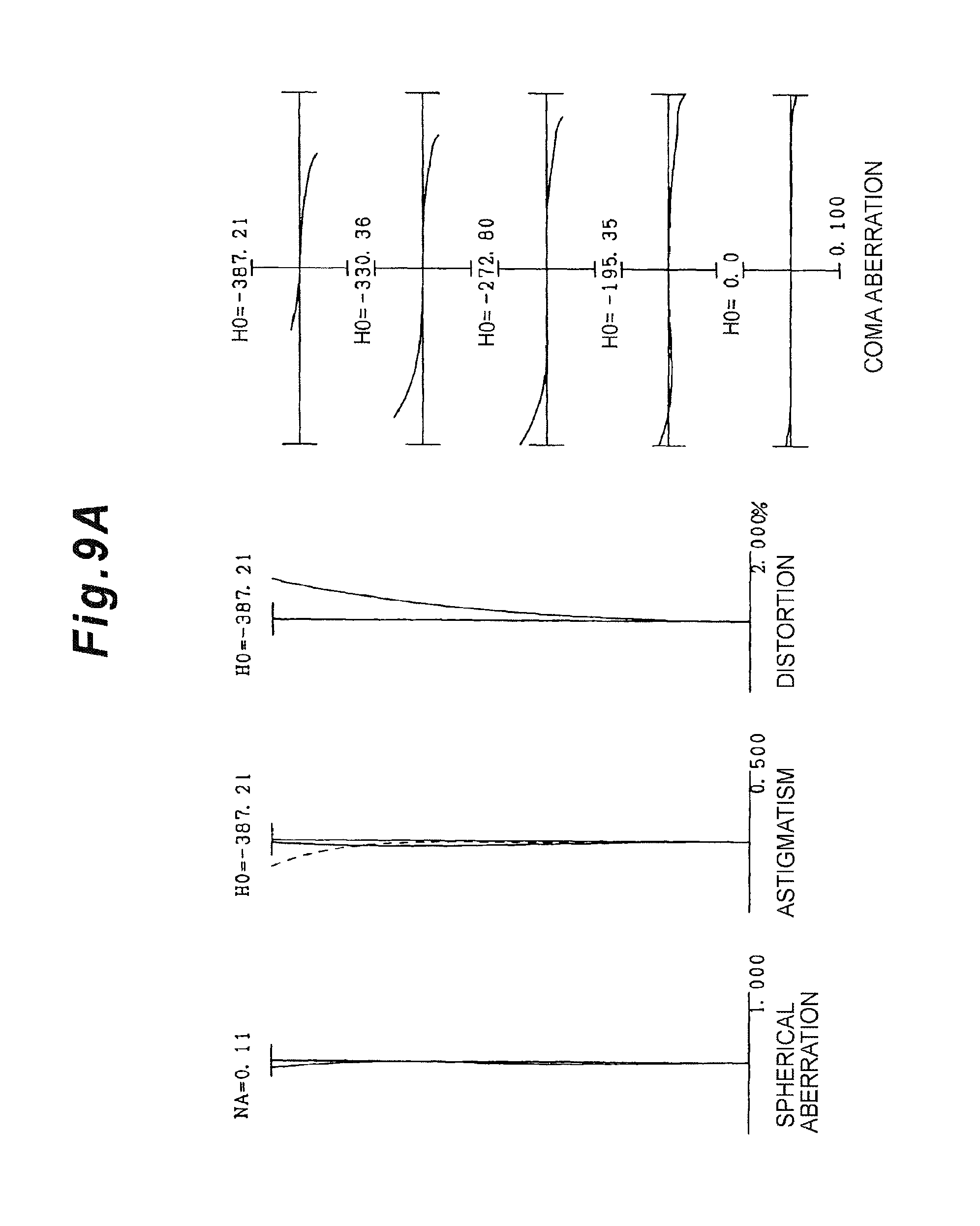
D00016
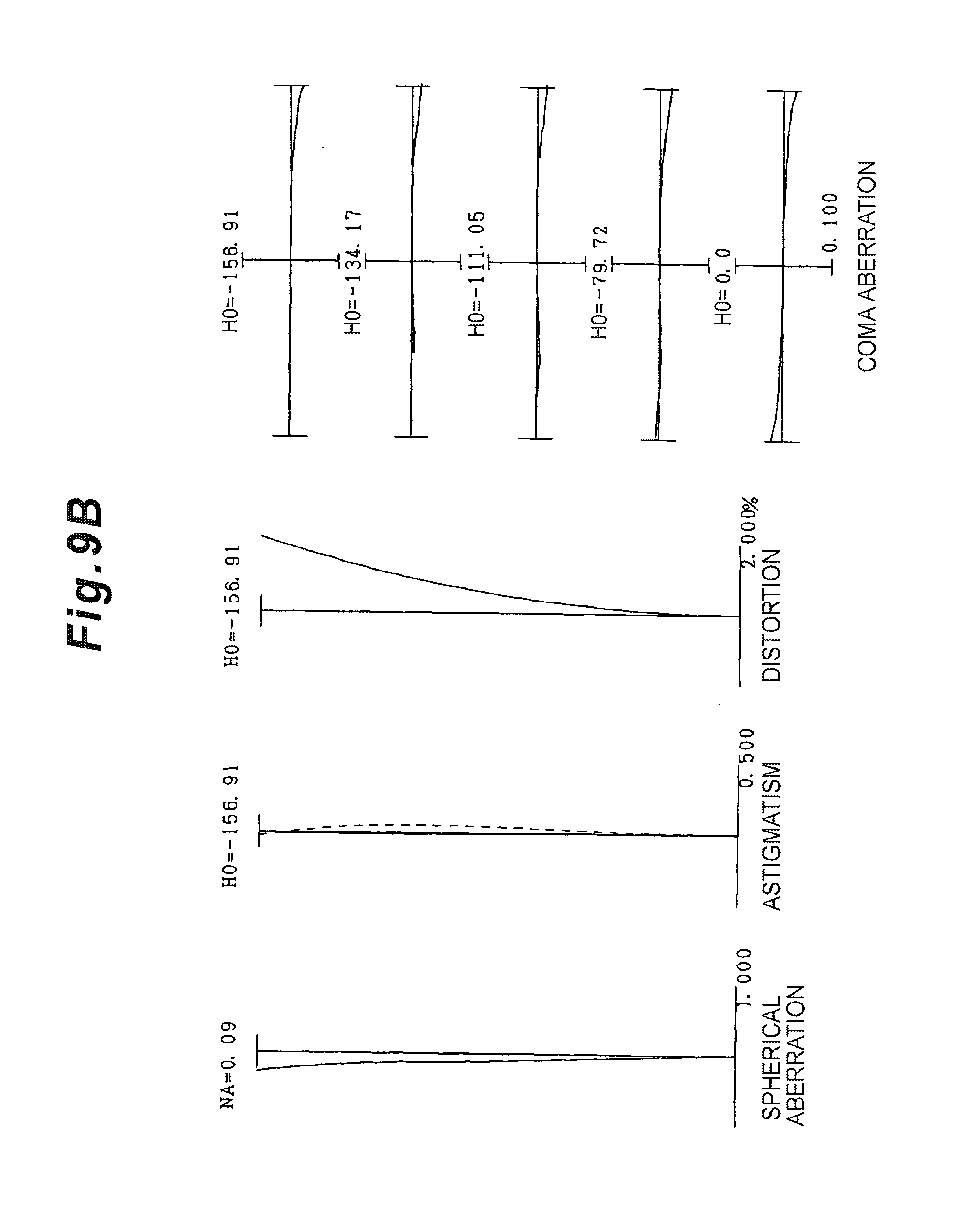
D00017
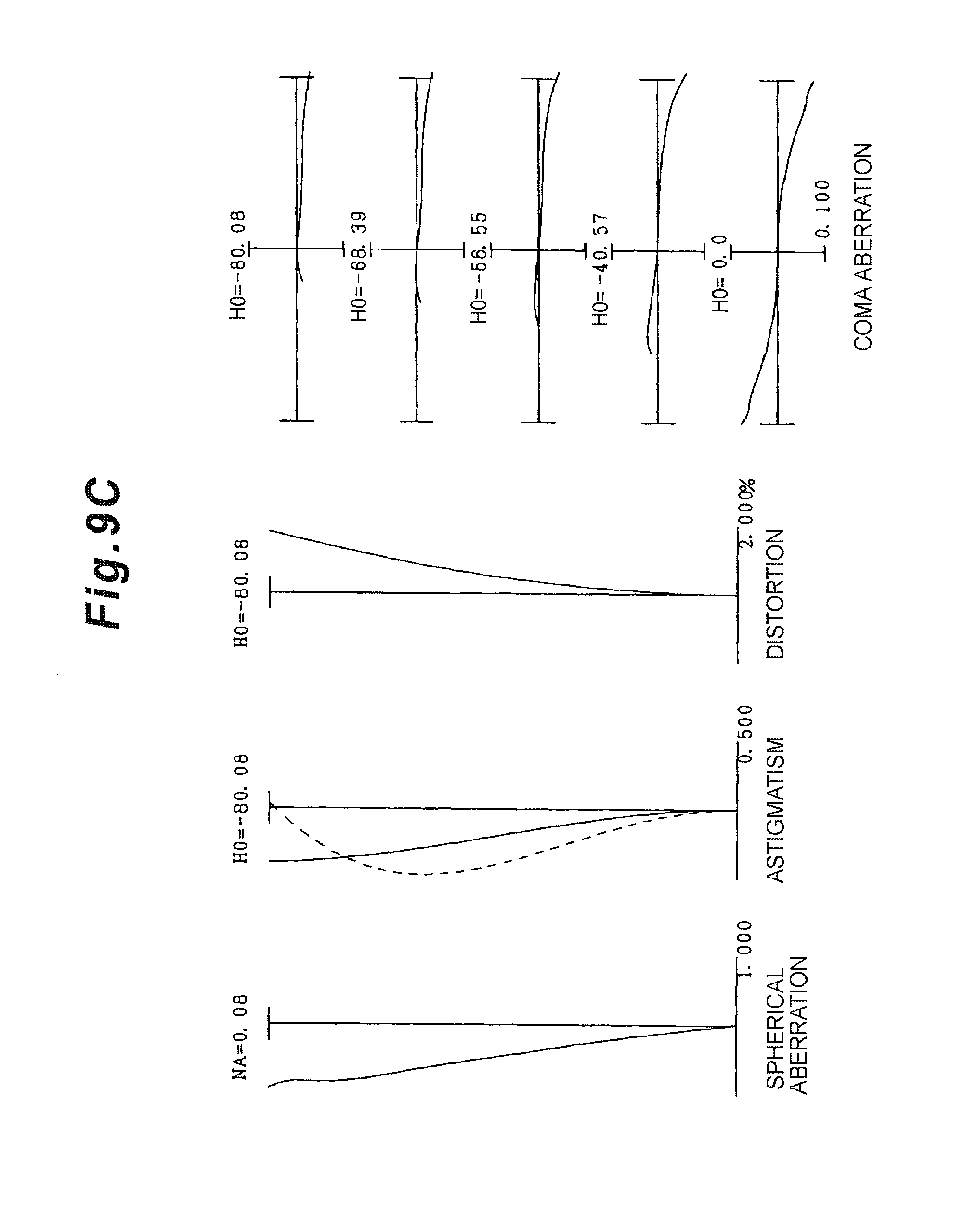
D00018

D00019

D00020

D00021

D00022

D00023

D00024

D00025

D00026

D00027

D00028

D00029

D00030

D00031

D00032

D00033
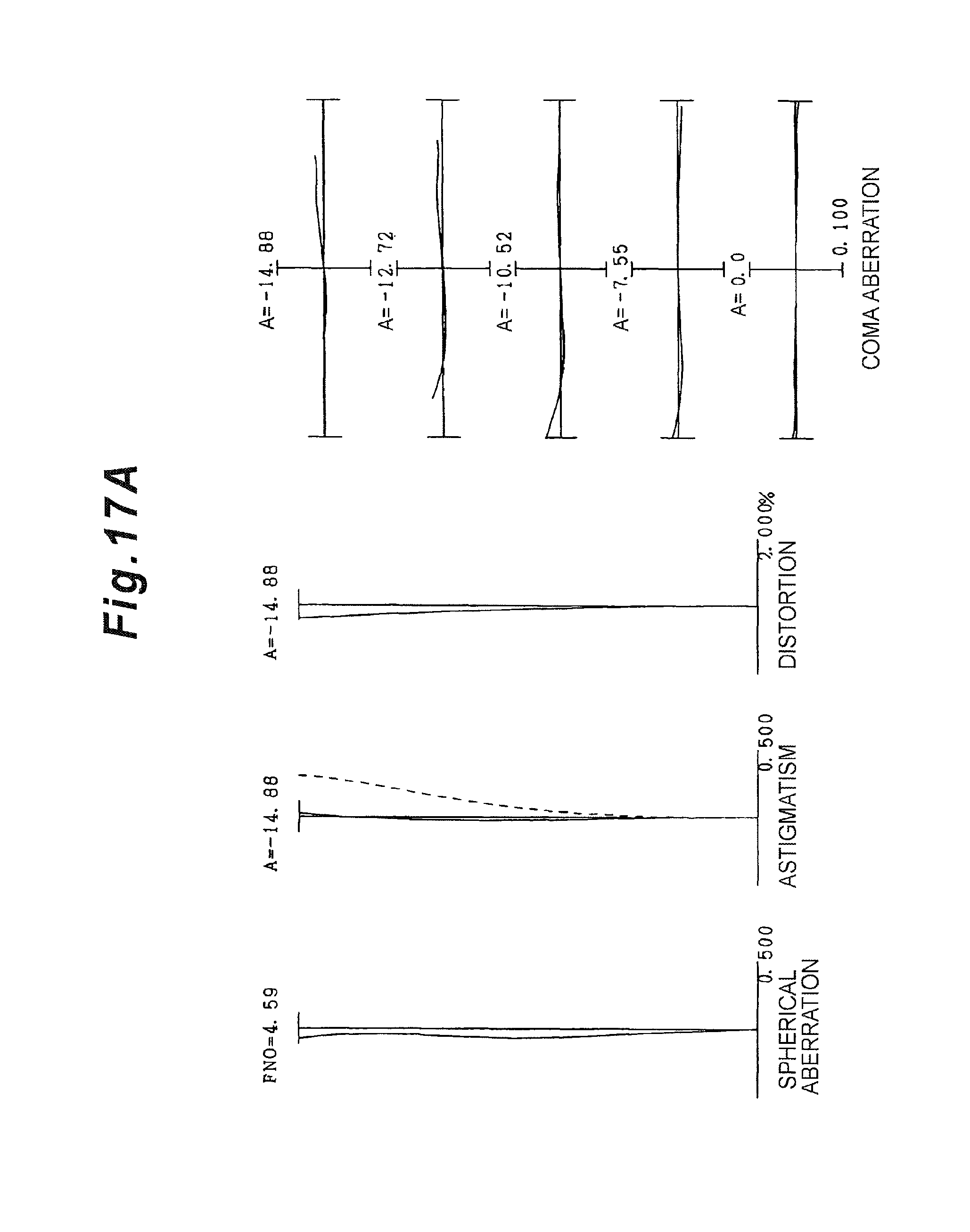
D00034

D00035

D00036
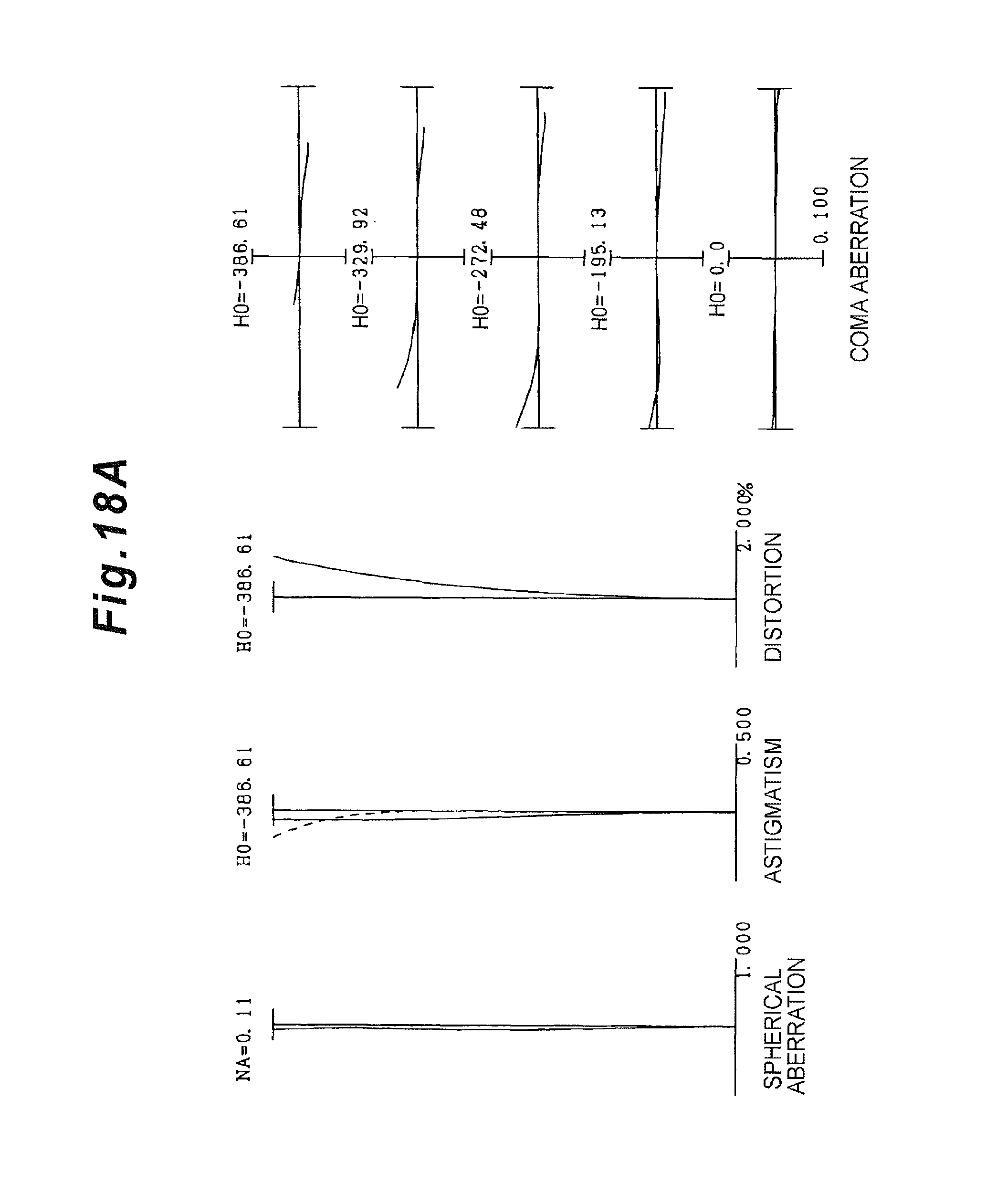
D00037

D00038

D00039

D00040
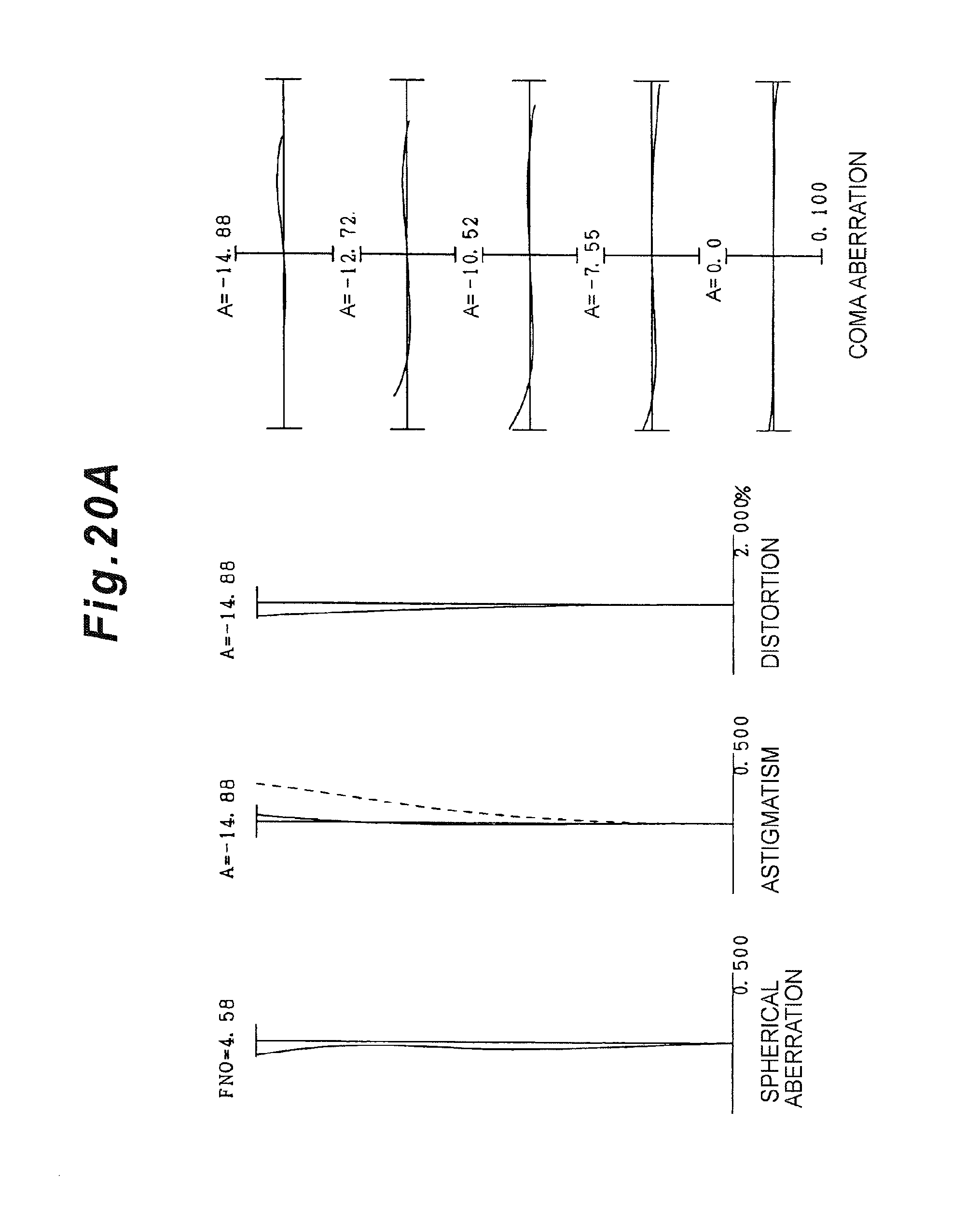
D00041

D00042

D00043

D00044

D00045

D00046

D00047

D00048

D00049

D00050

D00051

D00052

D00053
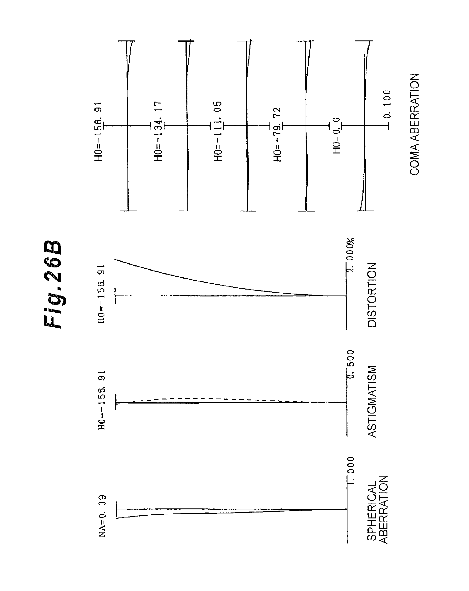
D00054

D00055

D00056

D00057

D00058

D00059

D00060

D00061

D00062

D00063

D00064

D00065

D00066

D00067

D00068

D00069

D00070

D00071

D00072

D00073

D00074

D00075

D00076

D00077

D00078

D00079

D00080

D00081

D00082

D00083

D00084

D00085

D00086

D00087

D00088

D00089

D00090
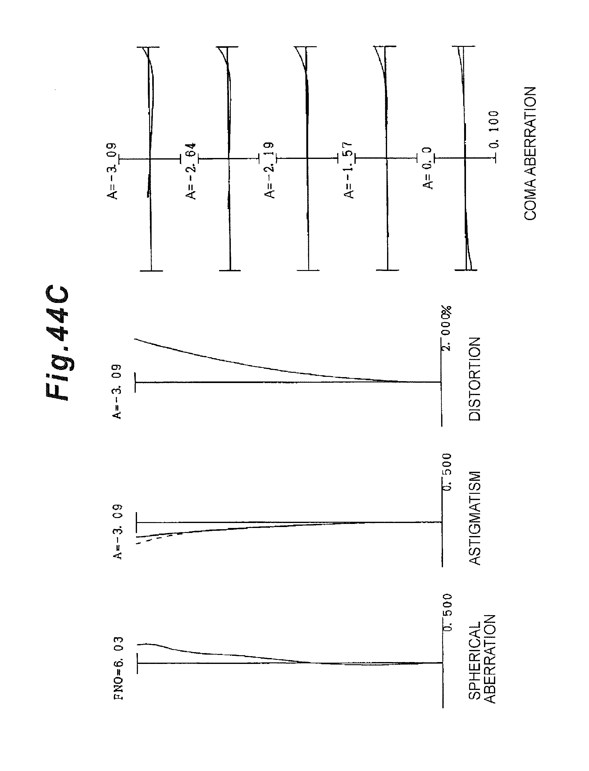
D00091

D00092

D00093

D00094

D00095

D00096

D00097

D00098

D00099

D00100

D00101

D00102

D00103

D00104

D00105

D00106

D00107

D00108
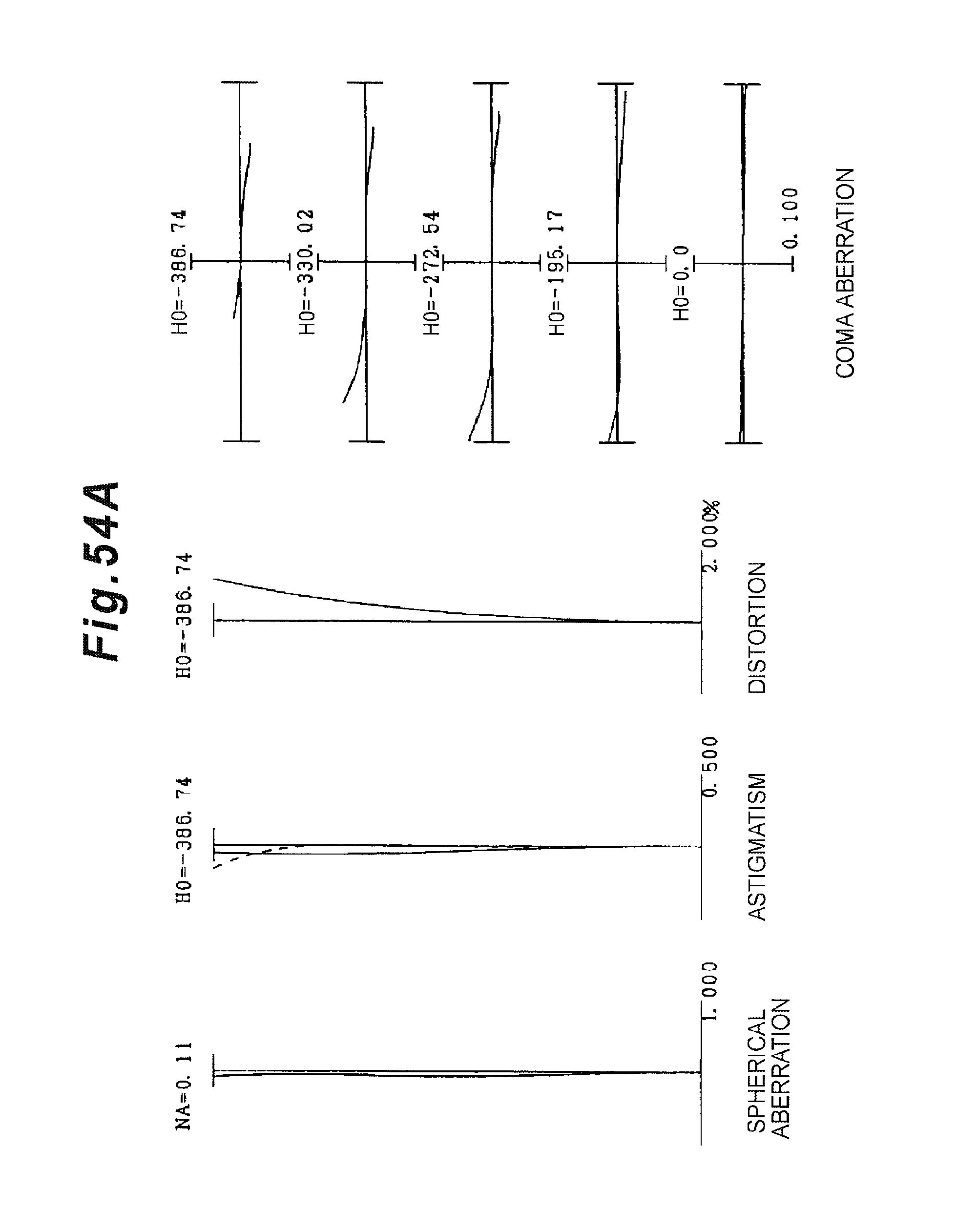
D00109

D00110

D00111

D00112

D00113
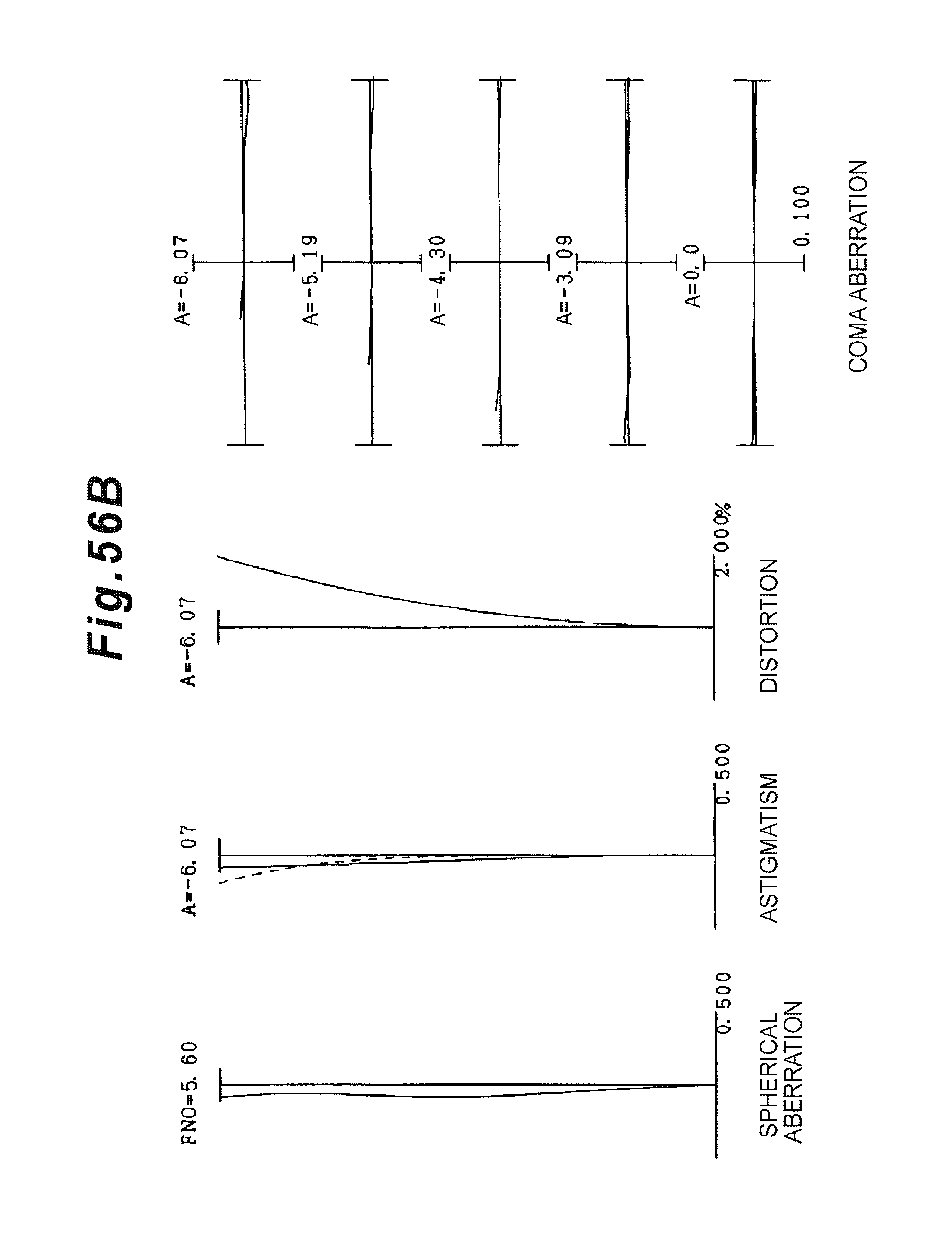
D00114

D00115

D00116

D00117

D00118

D00119

D00120

D00121
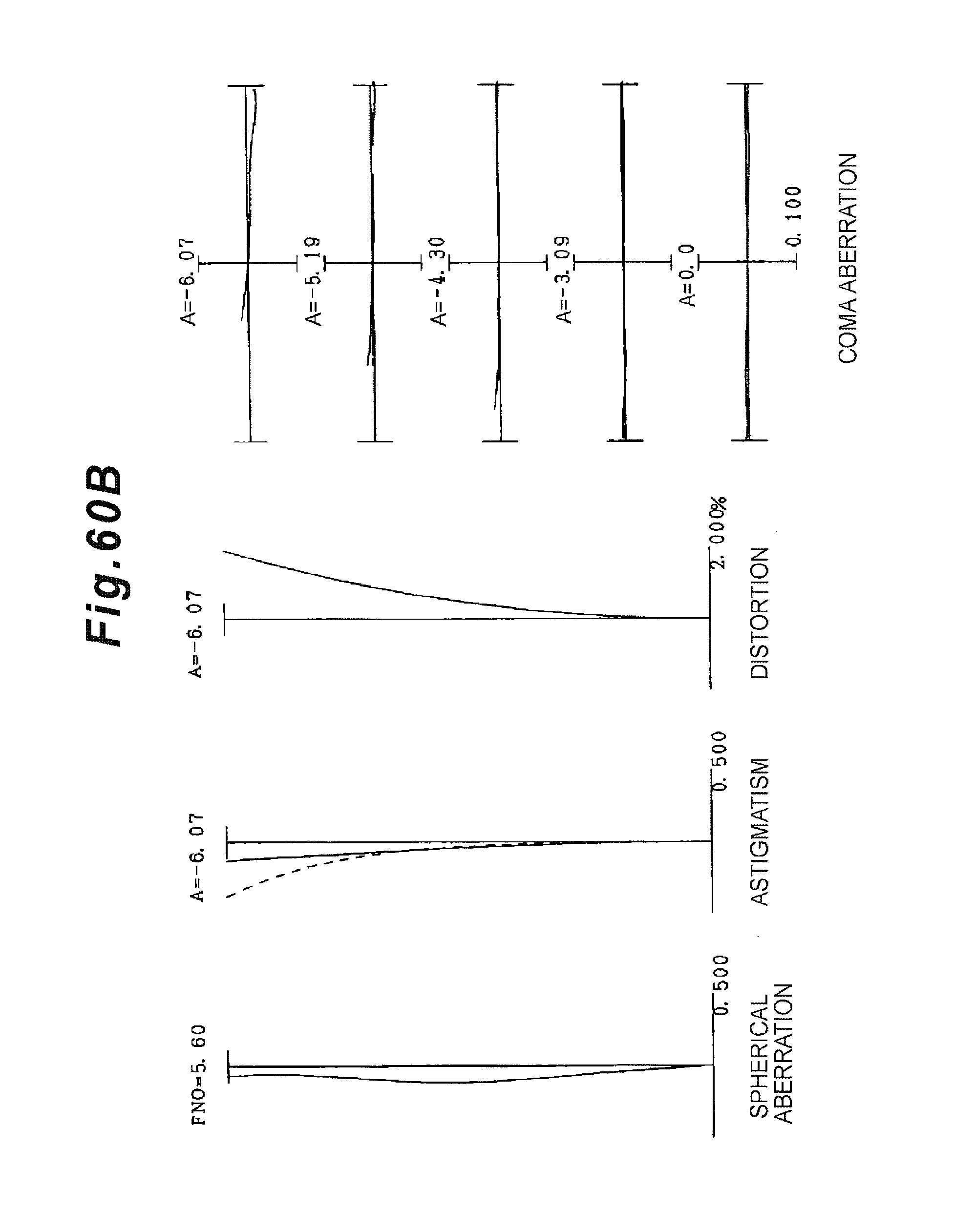
D00122

D00123

D00124
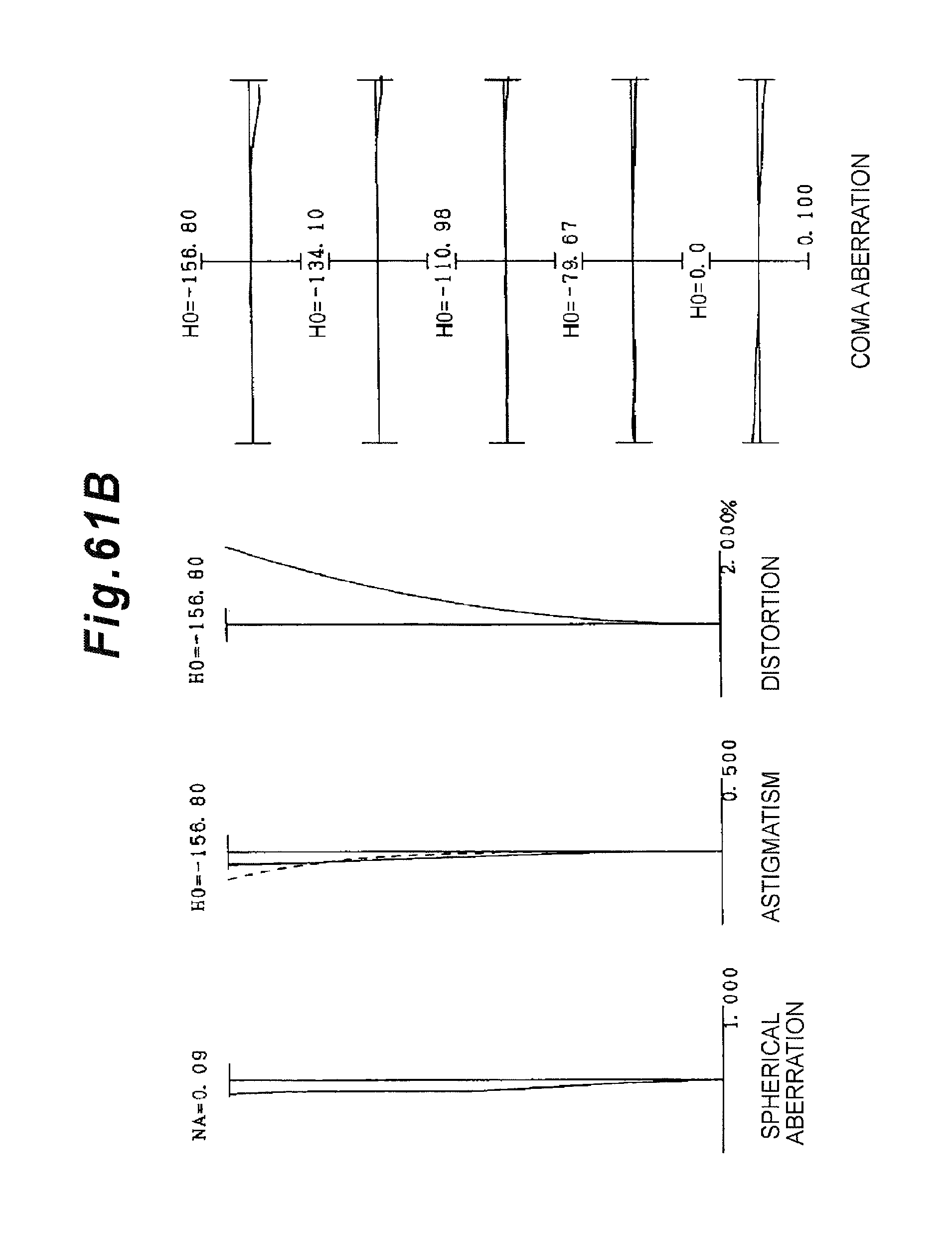
D00125

D00126

D00127

D00128

D00129

D00130

D00131

D00132
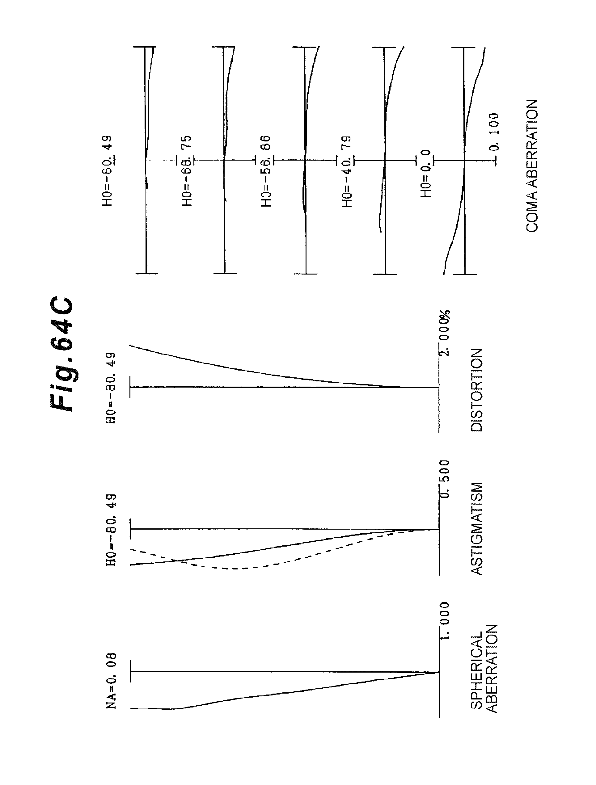
D00133

D00134

D00135

D00136

D00137
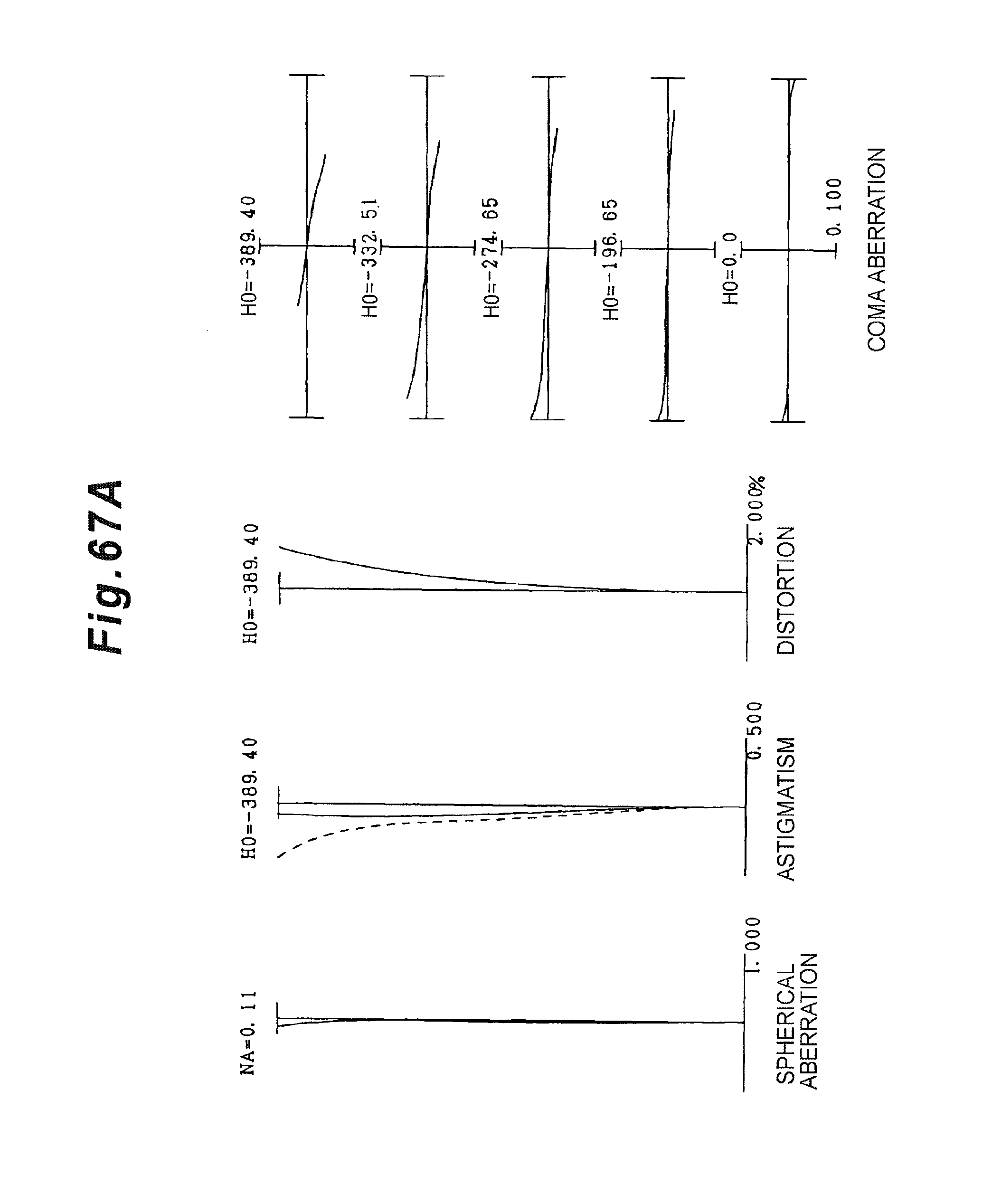
D00138

D00139

D00140

D00141

D00142

D00143

D00144

D00145

D00146

D00147

D00148

D00149

D00150

D00151

D00152

D00153

D00154

D00155

D00156

D00157

D00158

D00159

D00160
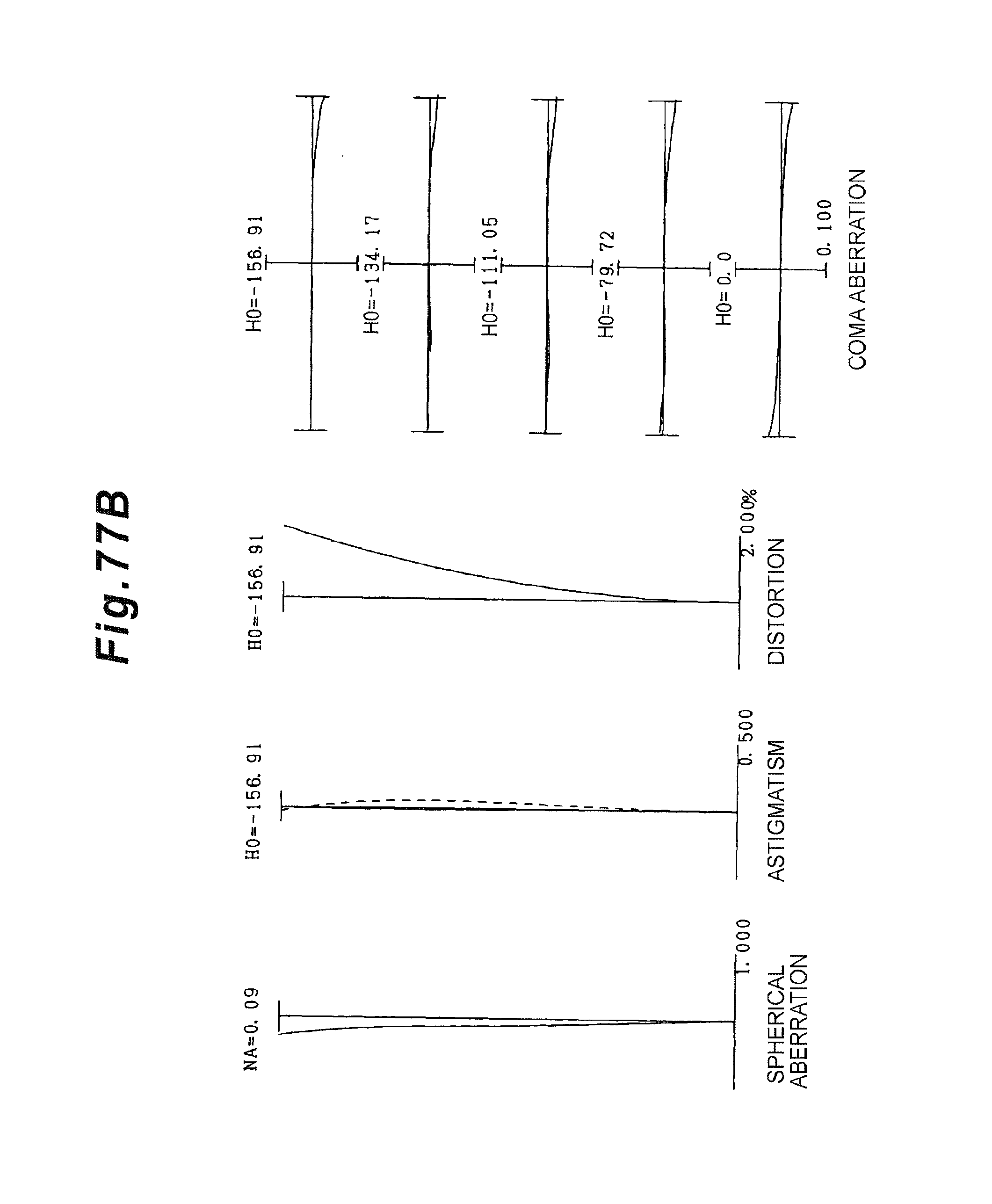
D00161

D00162

D00163

D00164

D00165

D00166

D00167

D00168

D00169

D00170

D00171

D00172

D00173

D00174

D00175

D00176

D00177

D00178

D00179

D00180

D00181

D00182

D00183

D00184

D00185

D00186

D00187

D00188

D00189

D00190

D00191

D00192

D00193

D00194

D00195
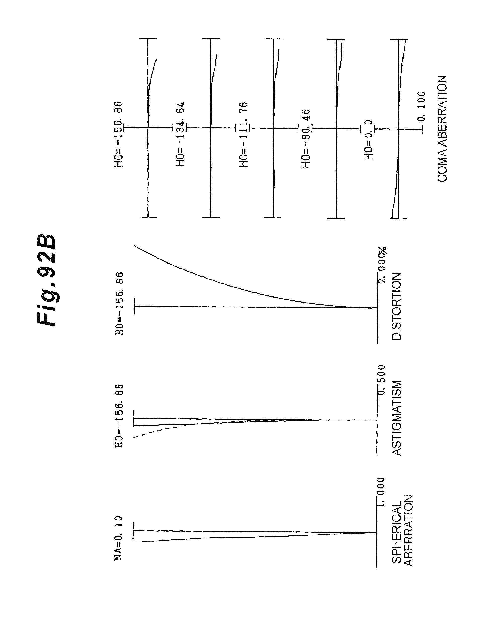
D00196

D00197

D00198

D00199

D00200

D00201

D00202

D00203

D00204

D00205

D00206

D00207

D00208

XML
uspto.report is an independent third-party trademark research tool that is not affiliated, endorsed, or sponsored by the United States Patent and Trademark Office (USPTO) or any other governmental organization. The information provided by uspto.report is based on publicly available data at the time of writing and is intended for informational purposes only.
While we strive to provide accurate and up-to-date information, we do not guarantee the accuracy, completeness, reliability, or suitability of the information displayed on this site. The use of this site is at your own risk. Any reliance you place on such information is therefore strictly at your own risk.
All official trademark data, including owner information, should be verified by visiting the official USPTO website at www.uspto.gov. This site is not intended to replace professional legal advice and should not be used as a substitute for consulting with a legal professional who is knowledgeable about trademark law.