Optical encoder for detecting rotational and axial movement
Rothkopf , et al. Ja
U.S. patent number 10,190,891 [Application Number 14/333,416] was granted by the patent office on 2019-01-29 for optical encoder for detecting rotational and axial movement. This patent grant is currently assigned to Apple Inc.. The grantee listed for this patent is Apple Inc.. Invention is credited to Colin M. Ely, Prashanth S. Holenarsipur, Fletcher R. Rothkopf.


| United States Patent | 10,190,891 |
| Rothkopf , et al. | January 29, 2019 |
Optical encoder for detecting rotational and axial movement
Abstract
Embodiments of the present disclosure provide an optical encoder for an electronic device. The optical encoder comprises an elongated shaft having an encoding pattern made up of axial markings and radial markings. The encoding pattern may be disposed around a circumference of the elongated shaft. The optical encoder also includes an optical sensor. In embodiments, the optical sensor includes an emitter and a photodiode array. The emitter causes light to shine on the encoding pattern. The encoding pattern reflects the light back to the photodiode array and the photodiode array determines movement of the shaft based on the reflected light.
| Inventors: | Rothkopf; Fletcher R. (Cupertino, CA), Holenarsipur; Prashanth S. (Cupertino, CA), Ely; Colin M. (Cupertino, CA) | ||||||||||
|---|---|---|---|---|---|---|---|---|---|---|---|
| Applicant: |
|
||||||||||
| Assignee: | Apple Inc. (Cupertino,
CA) |
||||||||||
| Family ID: | 65032705 | ||||||||||
| Appl. No.: | 14/333,416 | ||||||||||
| Filed: | July 16, 2014 |
| Current U.S. Class: | 1/1 |
| Current CPC Class: | G01D 5/3473 (20130101); G01P 3/486 (20130101); G01P 3/50 (20130101); G01P 3/36 (20130101); G01D 5/34746 (20130101); G01D 5/34792 (20130101) |
| Current International Class: | G01D 5/347 (20060101) |
| Field of Search: | ;250/231.1,231.13,231.14,231.16,231.17 ;356/615,616,617,622,620 ;33/1N,1M,1L,1PT ;341/11,13,14 |
References Cited [Referenced By]
U.S. Patent Documents
| 2237860 | April 1941 | Bolle |
| 2288215 | June 1942 | Taubert et al. |
| 2497935 | February 1950 | Feurer |
| 2771734 | November 1956 | Morf |
| 2788236 | April 1957 | Kafowi |
| 2797592 | July 1957 | Marrapese |
| 3040514 | June 1962 | Dinstman |
| 3056030 | September 1962 | Kelchner |
| 3130539 | April 1964 | Davis |
| 3355873 | December 1967 | Morf |
| 3410247 | November 1968 | Dronberger |
| 3495398 | February 1970 | Widmer et al. |
| 3577876 | May 1971 | Spadini |
| 3621649 | November 1971 | Vulcan et al. |
| 3662618 | May 1972 | Kroll et al. |
| 4007347 | February 1977 | Haber |
| 4031341 | June 1977 | Wuthrich et al. |
| 4037068 | July 1977 | Gaynor |
| 4077200 | March 1978 | Schneider |
| 4170104 | October 1979 | Yamagata |
| 4258096 | March 1981 | LaMarche |
| 4287400 | September 1981 | Kitik |
| 4289400 | September 1981 | Kubola et al. |
| 4311026 | January 1982 | Ochoa |
| 4311990 | January 1982 | Burke |
| 4324956 | April 1982 | Sakakino et al. |
| 4345119 | August 1982 | Latasiewicz |
| 4364674 | December 1982 | Tesch |
| 4379642 | April 1983 | Meyrat |
| 4395134 | July 1983 | Luce |
| 4396298 | August 1983 | Ripley |
| 4417824 | November 1983 | Paterson et al. |
| 4581509 | April 1986 | Sanford et al. |
| 4593194 | June 1986 | Graham et al. |
| 4600316 | July 1986 | Besson |
| 4617461 | October 1986 | Subbarao et al. |
| 4634861 | January 1987 | Ching et al. |
| 4641026 | February 1987 | Garcia, Jr. |
| 4670737 | June 1987 | Rilling |
| 4766642 | August 1988 | Gaffney et al. |
| 4783772 | November 1988 | Umemoto et al. |
| 4884073 | November 1989 | Souloumiac |
| 4914831 | April 1990 | Kanezashi et al. |
| 4922070 | May 1990 | Dorkinski |
| 4931794 | June 1990 | Haag |
| 4952799 | August 1990 | Loewen |
| 4980685 | December 1990 | Souloumiac et al. |
| 4987299 | January 1991 | Kobayashi |
| 5034602 | July 1991 | Garcia et al. |
| 5214278 | May 1993 | Banda |
| 5258592 | November 1993 | Nishikawa et al. |
| 5288993 | February 1994 | Bidiville |
| 5347123 | September 1994 | Jackson et al. |
| 5383166 | January 1995 | Gallay |
| 5471054 | November 1995 | Watanabe |
| 5509174 | April 1996 | Worrell |
| 5572314 | November 1996 | Hyman et al. |
| 5583560 | December 1996 | Florin et al. |
| 5631881 | May 1997 | Pessey et al. |
| 5726645 | March 1998 | Kamon et al. |
| 5748111 | May 1998 | Bates |
| 5825353 | October 1998 | Will |
| 5841050 | November 1998 | Clift et al. |
| 5847335 | December 1998 | Sugahara |
| 5847694 | December 1998 | Redford |
| 5867082 | February 1999 | Van Zeeland |
| 5943233 | August 1999 | Ebina |
| 5953001 | September 1999 | Challener et al. |
| 5960366 | September 1999 | Duwaer et al. |
| 5963332 | October 1999 | Feldman et al. |
| 6069567 | May 2000 | Zawilski |
| 6134189 | October 2000 | Carrard |
| 6154201 | November 2000 | Levin et al. |
| 6175679 | January 2001 | Veligdan et al. |
| 6246050 | June 2001 | Tullis |
| 6252825 | June 2001 | Perotto |
| 6304247 | October 2001 | Black |
| 6355891 | March 2002 | Ikunami |
| 6392640 | May 2002 | Will |
| 6396006 | May 2002 | Yokoji et al. |
| 6422740 | July 2002 | Leuenberger |
| 6477117 | November 2002 | Narayanaswami et al. |
| 6502982 | January 2003 | Bach et al. |
| 6525278 | February 2003 | Villain et al. |
| 6556222 | April 2003 | Narayanaswami |
| 6575618 | June 2003 | Inoue et al. |
| 6587400 | July 2003 | Line |
| 6646635 | November 2003 | Pogatetz et al. |
| 6661438 | November 2003 | Billman |
| 6672758 | January 2004 | Ehrsam et al. |
| 6707027 | March 2004 | Liess et al. |
| 6794992 | September 2004 | Rogers |
| 6809275 | October 2004 | Cheng |
| 6834430 | December 2004 | Worrell |
| 6846998 | January 2005 | Hasumi et al. |
| 6888076 | May 2005 | Hetherington |
| 6896403 | May 2005 | Gau |
| 6909378 | June 2005 | Lambrechts et al. |
| 6914551 | July 2005 | Vidal |
| 6961099 | November 2005 | Takano et al. |
| 6963039 | November 2005 | Weng et al. |
| 6977868 | December 2005 | Brewer et al. |
| 6985107 | January 2006 | Anson |
| 6998553 | February 2006 | Hisamune et al. |
| 7016263 | March 2006 | Gueissaz et al. |
| 7034237 | April 2006 | Ferri et al. |
| 7081905 | July 2006 | Raghunath et al. |
| 7102626 | September 2006 | Denny, III |
| 7111365 | September 2006 | Howie, Jr. |
| 7119289 | October 2006 | Lacroix |
| 7167083 | January 2007 | Giles |
| 7202851 | April 2007 | Cunningham et al. |
| 7244927 | July 2007 | Huynh |
| 7265336 | September 2007 | Hataguchi et al. |
| 7274303 | September 2007 | Dresti et al. |
| 7285738 | October 2007 | Lavigne et al. |
| 7292741 | November 2007 | Ishiyama et al. |
| 7345513 | March 2008 | Gropper et al. |
| 7358481 | April 2008 | Yeoh et al. |
| 7371745 | May 2008 | Ebright et al. |
| 7385874 | June 2008 | Vuilleumier |
| 7404667 | July 2008 | Born et al. |
| 7465917 | December 2008 | Chin et al. |
| 7506269 | March 2009 | Lang et al. |
| 7520664 | April 2009 | Wai |
| 7528824 | May 2009 | Kong |
| 7545367 | June 2009 | Sunda et al. |
| 7591582 | September 2009 | Hiranuma et al. |
| 7593755 | September 2009 | Colando et al. |
| 7605846 | October 2009 | Watanabe |
| 7634263 | December 2009 | Louch et al. |
| 7646677 | January 2010 | Nakamura |
| 7682070 | March 2010 | Burton |
| 7708457 | May 2010 | Girardin |
| 7710456 | May 2010 | Koshiba et al. |
| 7732724 | June 2010 | Otani et al. |
| 7761246 | July 2010 | Matsui |
| 7763819 | July 2010 | Ieda et al. |
| 7772507 | August 2010 | Orr |
| 7778115 | August 2010 | Ruchonnet |
| 7781726 | August 2010 | Matsui |
| RE41637 | September 2010 | O'Hara et al. |
| 7791597 | September 2010 | Silverstein et al. |
| 7856255 | December 2010 | Tsuchiya et al. |
| 7858583 | December 2010 | Schmidt et al. |
| 7865324 | January 2011 | Lindberg |
| 7946758 | May 2011 | Mooring |
| 7999199 | August 2011 | Villain |
| 8063892 | November 2011 | Shahoian et al. |
| 8138488 | March 2012 | Grot |
| 8143981 | March 2012 | Washizu et al. |
| 8167126 | May 2012 | Stiehl |
| 8169402 | May 2012 | Shahoian et al. |
| 8188989 | May 2012 | Levin et al. |
| 8195313 | June 2012 | Fadell et al. |
| 8229535 | July 2012 | Mensinger et al. |
| 8248815 | August 2012 | Yang et al. |
| 8263886 | September 2012 | Lin et al. |
| 8263889 | September 2012 | Takahashi et al. |
| 8294670 | October 2012 | Griffin et al. |
| 8312495 | November 2012 | Vanderhoff |
| 8368677 | February 2013 | Yamamoto |
| 8371745 | February 2013 | Manni |
| 8373661 | February 2013 | Lan et al. |
| 8410971 | April 2013 | Friedlander |
| 8432368 | April 2013 | Momeyer et al. |
| 8439559 | May 2013 | Luk et al. |
| 8441450 | May 2013 | Degner et al. |
| 8446713 | May 2013 | Lai |
| 8456430 | June 2013 | Oliver et al. |
| 8477118 | July 2013 | Lan et al. |
| 8487237 | July 2013 | Watanabe |
| 8493190 | July 2013 | Periquet et al. |
| 8508511 | August 2013 | Tanaka et al. |
| 8525777 | September 2013 | Stavely et al. |
| 8562489 | October 2013 | Burton et al. |
| 8568313 | October 2013 | Sadhu |
| 8576044 | November 2013 | Chapman |
| 8576171 | November 2013 | Grant |
| 8593598 | November 2013 | Chen et al. |
| 8607662 | December 2013 | Huang |
| 8614881 | December 2013 | Yoo |
| 8666682 | March 2014 | LaVigne et al. |
| 8704787 | April 2014 | Yamamoto |
| 8711093 | April 2014 | Ong et al. |
| 8743088 | June 2014 | Watanabe |
| 8783944 | July 2014 | Doi |
| 8816962 | August 2014 | Obermeyer et al. |
| 8824245 | September 2014 | Lau et al. |
| 8847741 | September 2014 | Birnbaum et al. |
| 8859971 | October 2014 | Weber |
| 8860674 | October 2014 | Lee et al. |
| 8863219 | October 2014 | Brown et al. |
| D717679 | November 2014 | Anderssen |
| 8878657 | November 2014 | Periquet et al. |
| 8885856 | November 2014 | Sacha |
| 8890045 | November 2014 | Toh et al. |
| 8895911 | November 2014 | Takahashi |
| 8905631 | December 2014 | Sakurazawa et al. |
| 8908477 | December 2014 | Peters et al. |
| 8920022 | December 2014 | Ishida et al. |
| 8922399 | December 2014 | Bajaj et al. |
| 8928452 | January 2015 | Kim et al. |
| 8994694 | March 2015 | Lee et al. |
| 8994827 | March 2015 | Mistry et al. |
| 9024733 | May 2015 | Wouters |
| 9028134 | May 2015 | Koshoji et al. |
| 9030446 | May 2015 | Mistry et al. |
| 9034666 | May 2015 | Vaganov et al. |
| 9052696 | June 2015 | Breuillot et al. |
| 9086717 | July 2015 | Meerovitsch |
| 9101184 | August 2015 | Wilson |
| 9105413 | August 2015 | Hiranuma et al. |
| 9123483 | September 2015 | Ferri et al. |
| 9134145 | September 2015 | Shimizu |
| 9141087 | September 2015 | Brown et al. |
| 9176577 | November 2015 | Jangaard et al. |
| 9202372 | December 2015 | Reams et al. |
| 9213409 | December 2015 | Redelsheimer et al. |
| 9223296 | December 2015 | Yang et al. |
| 9241635 | January 2016 | Yuen et al. |
| 9244438 | January 2016 | Hoover et al. |
| 9256209 | February 2016 | Yang et al. |
| 9277156 | March 2016 | Bennett et al. |
| 9285926 | March 2016 | Yang et al. |
| 9350850 | May 2016 | Pope et al. |
| 9386932 | July 2016 | Chatterjee et al. |
| 9426275 | August 2016 | Eim et al. |
| 9430042 | August 2016 | Levin |
| 9437357 | September 2016 | Furuki et al. |
| 9449770 | September 2016 | Sanford et al. |
| 9501044 | November 2016 | Jackson et al. |
| 9520100 | December 2016 | Houjou et al. |
| 9532723 | January 2017 | Kim |
| 9545541 | January 2017 | Aragones et al. |
| 9552023 | January 2017 | Joo et al. |
| 9599964 | March 2017 | Gracia |
| 9638587 | May 2017 | Marquas et al. |
| 9659482 | May 2017 | Yang et al. |
| 9680831 | June 2017 | Jooste et al. |
| 9709956 | July 2017 | Ely et al. |
| D800172 | October 2017 | Akana |
| 9797752 | October 2017 | Ruh et al. |
| 9797753 | October 2017 | Gowreesunker et al. |
| 9800717 | October 2017 | Ma et al. |
| 9836025 | December 2017 | Ely et al. |
| 9891590 | February 2018 | Shim et al. |
| 9946297 | April 2018 | Nazzaro et al. |
| 10001817 | June 2018 | Zambetti et al. |
| 10025399 | July 2018 | Kim et al. |
| 2003/0174590 | September 2003 | Arikawa et al. |
| 2004/0047244 | March 2004 | Iino et al. |
| 2004/0082414 | April 2004 | Knox |
| 2004/0130971 | July 2004 | Ecoffet et al. |
| 2004/0264301 | December 2004 | Howard et al. |
| 2005/0075558 | April 2005 | Vecerina |
| 2005/0157971 | July 2005 | Juijve et al. |
| 2006/0091304 | May 2006 | Saint Clair |
| 2006/0250377 | November 2006 | Zadesky et al. |
| 2007/0013775 | January 2007 | Shin |
| 2007/0050054 | March 2007 | Sambandam Guruparan et al. |
| 2007/0146348 | June 2007 | Villain |
| 2007/0211042 | September 2007 | Kim et al. |
| 2007/0222756 | September 2007 | Wu et al. |
| 2007/0229671 | October 2007 | Takeshita et al. |
| 2007/0247421 | October 2007 | Orsley et al. |
| 2008/0130914 | June 2008 | Cho |
| 2008/0278445 | November 2008 | Sweetser et al. |
| 2009/0051649 | February 2009 | Rondel |
| 2009/0073119 | March 2009 | Phan Le |
| 2009/0122656 | May 2009 | Bonnet et al. |
| 2009/0146975 | June 2009 | Chang |
| 2009/0152452 | June 2009 | Lee et al. |
| 2009/0177416 | July 2009 | Nilsagard |
| 2009/0217207 | August 2009 | Kagermeier et al. |
| 2009/0285443 | November 2009 | Camp et al. |
| 2009/0312051 | December 2009 | Hansson et al. |
| 2010/0033430 | February 2010 | Kakutani et al. |
| 2010/0053468 | March 2010 | Havrill |
| 2010/0081375 | April 2010 | Rosenblatt et al. |
| 2010/0149099 | June 2010 | Elias |
| 2011/0007468 | January 2011 | Burton et al. |
| 2011/0090148 | April 2011 | Li et al. |
| 2011/0158057 | June 2011 | Brewer et al. |
| 2011/0242064 | October 2011 | Ono et al. |
| 2012/0023459 | January 2012 | Westerman |
| 2012/0067711 | March 2012 | Yang |
| 2012/0068833 | March 2012 | Rothkopf et al. |
| 2012/0068857 | March 2012 | Rothkopf et al. |
| 2012/0075082 | March 2012 | Rothkopf et al. |
| 2012/0112859 | May 2012 | Park et al. |
| 2012/0113044 | May 2012 | Strazisar et al. |
| 2012/0177237 | July 2012 | Shukla et al. |
| 2012/0206248 | August 2012 | Biggs |
| 2012/0272784 | November 2012 | Bailey et al. |
| 2013/0037396 | February 2013 | Yu |
| 2013/0087443 | April 2013 | Kikuchi |
| 2013/0191220 | July 2013 | Dent et al. |
| 2013/0261405 | October 2013 | Lee et al. |
| 2013/0335196 | December 2013 | Zhang et al. |
| 2014/0071050 | March 2014 | Armstrong-Muntner |
| 2014/0071098 | March 2014 | You |
| 2014/0132516 | May 2014 | Tsai et al. |
| 2014/0197936 | July 2014 | Biggs et al. |
| 2014/0268150 | September 2014 | Leung et al. |
| 2014/0327630 | November 2014 | Burr et al. |
| 2014/0340318 | November 2014 | Stringer et al. |
| 2014/0347289 | November 2014 | Suh et al. |
| 2015/0041289 | February 2015 | Ely |
| 2015/0051671 | February 2015 | Browne et al. |
| 2015/0098309 | April 2015 | Adams et al. |
| 2015/0124415 | May 2015 | Goyal et al. |
| 2015/0186609 | July 2015 | Utter, II |
| 2015/0221460 | August 2015 | Teplitxky et al. |
| 2015/0227217 | August 2015 | Fukumoto |
| 2015/0341031 | November 2015 | Marquas et al. |
| 2015/0366098 | December 2015 | Lapetina et al. |
| 2016/0018846 | January 2016 | Zenoff |
| 2016/0054813 | February 2016 | Shediwy et al. |
| 2016/0061636 | March 2016 | Gowreesunker et al. |
| 2016/0062623 | March 2016 | Howard et al. |
| 2016/0069713 | March 2016 | Ruh et al. |
| 2016/0098016 | April 2016 | Ely et al. |
| 2016/0109861 | April 2016 | Kim et al. |
| 2016/0116306 | April 2016 | Ferri et al. |
| 2016/0147432 | May 2016 | Shi et al. |
| 2016/0168178 | June 2016 | Misra |
| 2016/0170598 | June 2016 | Zambetti et al. |
| 2016/0170608 | June 2016 | Zambetti et al. |
| 2016/0170624 | June 2016 | Zambetti et al. |
| 2016/0253487 | September 2016 | Sarkar et al. |
| 2016/0258784 | September 2016 | Boonsom et al. |
| 2016/0259301 | September 2016 | Ely |
| 2016/0306437 | October 2016 | Zhang et al. |
| 2016/0306446 | October 2016 | Chung et al. |
| 2016/0313703 | October 2016 | Ely et al. |
| 2016/0320583 | November 2016 | Hall, Jr. |
| 2016/0327911 | November 2016 | Eim et al. |
| 2016/0378072 | December 2016 | Ely et al. |
| 2017/0003655 | January 2017 | Ely |
| 2017/0010751 | January 2017 | Shedletsky |
| 2017/0011210 | January 2017 | Cheong et al. |
| 2017/0011873 | January 2017 | Ely et al. |
| 2017/0031449 | February 2017 | Karsten et al. |
| 2017/0045958 | February 2017 | Battlogg |
| 2017/0061863 | March 2017 | Eguchi |
| 2017/0069443 | March 2017 | Wang et al. |
| 2017/0069444 | March 2017 | Wang et al. |
| 2017/0069447 | March 2017 | Wang et al. |
| 2017/0104902 | April 2017 | Kim et al. |
| 2017/0115757 | April 2017 | Armstrong-Muntner |
| 2017/0139489 | May 2017 | Chen et al. |
| 2017/0216668 | August 2017 | Burton et al. |
| 2017/0238138 | August 2017 | Aminzade |
| 2017/0251561 | August 2017 | Fleck et al. |
| 2017/0269715 | September 2017 | Kim et al. |
| 2017/0285404 | October 2017 | Kubota et al. |
| 2017/0301314 | October 2017 | Kim et al. |
| 2017/0308039 | October 2017 | Ely et al. |
| 2017/0331869 | November 2017 | Bendahan et al. |
| 2017/0357465 | December 2017 | Dzeryn et al. |
| 2018/0018026 | January 2018 | Bushnell et al. |
| 2018/0031395 | February 2018 | Ruh et al. |
| 1888928 | Jan 1937 | CH | |||
| 1302740 | Sep 2001 | CN | |||
| 1445627 | Oct 2003 | CN | |||
| 1624427 | Jun 2005 | CN | |||
| 101201587 | Jun 2008 | CN | |||
| 101750958 | Jun 2010 | CN | |||
| 101923314 | Dec 2010 | CN | |||
| 102890443 | Jan 2013 | CN | |||
| 202710937 | Jan 2013 | CN | |||
| 1 03191557 | Jul 2013 | CN | |||
| 103645804 | Mar 2014 | CN | |||
| 203564224 | Apr 2014 | CN | |||
| 103852090 | Jun 2014 | CN | |||
| 103956006 | Jul 2014 | CN | |||
| 203693601 | Jul 2014 | CN | |||
| 203732900 | Jul 2014 | CN | |||
| 103995456 | Aug 2014 | CN | |||
| 203941395 | Nov 2014 | CN | |||
| 104777987 | Apr 2015 | CN | |||
| 104880937 | Sep 2015 | CN | |||
| 204650147 | Sep 2015 | CN | |||
| 105096979 | Nov 2015 | CN | |||
| 105547146 | May 2016 | CN | |||
| 3706194 | Sep 1988 | DE | |||
| 102008023651 | Nov 2009 | DE | |||
| 0556155 | Aug 1993 | EP | |||
| 1345095 | Sep 2003 | EP | |||
| 1669724 | Jun 2006 | EP | |||
| 1832969 | Sep 2007 | EP | |||
| 2375295 | Oct 2011 | EP | |||
| 2720129 | Apr 2014 | EP | |||
| 2030093 | Oct 1970 | FR | |||
| 2801402 | May 2001 | FR | |||
| 2433211 | Jun 2007 | GB | |||
| S578582 | Jan 1982 | JP | |||
| S5734457 | Feb 1982 | JP | |||
| H02285214 | Nov 1990 | JP | |||
| H04093719 | Mar 1992 | JP | |||
| H05203465 | Aug 1993 | JP | |||
| H05312595 | Nov 1993 | JP | |||
| H06347293 | Dec 1994 | JP | |||
| H10161811 | Jun 1998 | JP | |||
| 11121210 | Apr 1999 | JP | |||
| H11191508 | Jul 1999 | JP | |||
| 2000337892 | Dec 2000 | JP | |||
| 2001084934 | Mar 2001 | JP | |||
| 2001202178 | Jul 2001 | JP | |||
| 2003050668 | Feb 2003 | JP | |||
| 2003151410 | May 2003 | JP | |||
| 2003331693 | Nov 2003 | JP | |||
| 2004184396 | Jul 2004 | JP | |||
| 2005017011 | Jan 2005 | JP | |||
| 2005063200 | Mar 2005 | JP | |||
| 2006164275 | Jun 2006 | JP | |||
| 2007248176 | Sep 2007 | JP | |||
| 2007311153 | Nov 2007 | JP | |||
| 2008053980 | Mar 2008 | JP | |||
| 2008122124 | May 2008 | JP | |||
| 2008122377 | May 2008 | JP | |||
| 2008170436 | Jul 2008 | JP | |||
| 2008235226 | Oct 2008 | JP | |||
| 2009070657 | Apr 2009 | JP | |||
| 2010032545 | Feb 2010 | JP | |||
| 2010165001 | Jul 2010 | JP | |||
| 2010186572 | Aug 2010 | JP | |||
| 2010243344 | Oct 2010 | JP | |||
| 2010244797 | Oct 2010 | JP | |||
| 2011165468 | Aug 2011 | JP | |||
| 2013057516 | Mar 2013 | JP | |||
| 2013079961 | May 2013 | JP | |||
| 2014174031 | Sep 2014 | JP | |||
| 20010030477 | Apr 2001 | KR | |||
| 20070014247 | Feb 2007 | KR | |||
| 20080045397 | May 2008 | KR | |||
| 20110011393 | Feb 2011 | KR | |||
| 1040225 | Nov 2014 | NL | |||
| 200633681 | Oct 2006 | TW | |||
| WO 01/022038 | Mar 2001 | WO | |||
| WO 01/069567 | Sep 2001 | WO | |||
| WO 10/058376 | May 2010 | WO | |||
| WO 12/083380 | Jun 2012 | WO | |||
| WO 14/018118 | Jan 2014 | WO | |||
| WO 15/147756 | Oct 2015 | WO | |||
| WO 16/155761 | Oct 2016 | WO | |||
Other References
|
Epstein et al., "Economical, High-Performance Optical Encoders," Hewlett-Packard Journal Oct. 1988, pp. 99-106 [text only version]. cited by applicant . Epstein et al., "Economical, High-Performance Optical Encoders," Hewlett-Packard Journal Oct. 1988, pp. 99-106. cited by applicant . Hewlett-Packard Journal, Oct. 1988, vol. 39, No. 5, 112 pages. cited by applicant . Krishnan et al., "A Miniature Surface Mount Reflective Optical Shaft Encoder," Hewlett-Packard Journal, Dec. 1996, Article 8, pp. 1-6. cited by applicant . U.S. Appl. No. 61/645,033, filed May 9, 2012, 84 pages. cited by applicant . DeskThorityNet, Optical Switch Keyboards, http://deskthority.net/keyboards-f2/optical-switch-keyboards-t1474.html, Jul. 11, 2015, 22 pages. cited by applicant . Author Unknown, "How Vesag Helps Kids Women and Visitors," http://www.sooperarticles.com/health-fitness-articles/children-health-art- icles/how-vesag-helps-kids-women-visitors-218542.html, 2 pages, at least as early as May 20, 2015. cited by applicant . Author Unknown, "mHealth," http://mhealth.vesag.com/?m=201012, 7 pages, Dec. 23, 2010. cited by applicant . Author Unknown, "mHealth Summit 2010," http://www.virtualpressoffice.com/eventsSubmenu.do?page=exhibitorPage&sho- wId= 1551 &companyId=5394, 5 pages, Nov. 18, 2010. cited by applicant . Author Unknown, "RedEye mini Plug-in Universal Remote Adapter for iPhone, iPod touch and iPad," Amazon.com, 4 pages, date unknown. cited by applicant . Author Unknown, "Re iPhone Universal Remote Control--Infrared Remote Control Accessory for iPhone and iPod touch," http://www.amazon.com/iPhone-Universal-Remote-Control-Accessory/dp/tech-d- ata/B0038Z4 . . . , 2 pages, at least as early as Jul. 15, 2010. cited by applicant . Author Unknown, "Vesag Wrist Watch for Dementia Care from VYZIN," http://vyasa-kaaranam-ketkadey.blogspot.com/2011/03/vesag-wrist-watch-for- -dementia-care.html, 2 pages, Mar. 31, 2011. cited by applicant . Author Unknown, "Vyzin Electronics Private Limited launches Vesag Watch," http://www.virtualpressoffice.com/showJointPage.do?page=jp&showId=1544, 5 pages, Jan. 6, 2011. cited by applicant . Author Unknown, "Vyzin Unveiled Personal Emergency Response System (PERS) with Remote Health Monitoring That Can Be Used for Entire Family," http://www.24-7pressrelease.com/press-release/vyzin-unveiled-personal-eme- rgency-response-system-pers-with-remote-health-monitoring-that-can-be-used- -for-entire-family-219317.php, 2 pages, Jun. 17, 2011. cited by applicant . IBM, "Additional Functionality Added to Cell Phone via "Learning" Function Button," www.ip.com, 2 pages, Feb. 21, 2007. cited by applicant . Kim, Joseph, "2010 mHealth Summit Emerges as Major One-Stop U.S. Venue for Mobile Health," http://www.medicineandtechnology.com/2010/08/2010-mhealth-summit-emerges-- as-major.html, 3 pages, Aug. 26, 2010. cited by applicant . Rick, "How VESAG Helps Health Conscious Citizens," http://sensetekgroup.com/2010/11/29/wireless-health-monitoring-system/, 2 pages, Nov. 29, 2010. cited by applicant . Sadhu, Rajendra, "How VESAG Helps People Who Want to `Be There`?," http://ezinearticles.com/?How-Vesag-Helps-People-Who-Want-to-Be-There?&id- -5423873, 1 page, Nov. 22, 2010. cited by applicant . Sadhu, Rajendra, "Mobile Innovation Helps Dementia and Alzheimer's Patients," http://www.itnewsafrica.com/2010/11/mobile-innovation-helps-dementia-anda- lzheimer%E2%80%99s-patients/, 3 pages, Nov. 22, 2010. cited by applicant . Sherr, Sol, "Input Devices," p. 55, Mar. 1988. cited by applicant . Tran et al., "Universal Programmable Remote Control/Telephone," www.ip.com, 2 pages, May 1, 1992. cited by applicant . GreyB, "Google Watch: Convert your arm into a keyboard," http://www.whatafuture.com/2014/02/28/google-smartwatch/#sthash.Yk35cDXK.- dpbs, 3 pages, Feb. 28, 2014. cited by applicant . U.S. Appl. No. 15/729,499, filed Oct. 10, 2017, Ruh et al. cited by applicant . Liess et al., "A miniaturized multidirectional optical motion sensor and input device based on laser self-mixing," Measurement Science and Technology, Institute of Physics Publishing, vol. 13, 2002, pp. 2001-2006. cited by applicant . Author Unknown, "Fossil Q ups smartwatch game with handsome design and build," Business Mirror, Makati City, Philippines, 3 pages, Dec. 20, 2016. cited by applicant . Author Unknown, "MyKronoz ZeTime: World's Most Funded Hybrid Smartwatch Raised over $3M on Kickstarter, Running until Apr. 27," Buisness Wire, New York, New York, 3 pages, Apr. 21, 2017. cited by applicant . Author Unknown, "Desirable Android Wear smartwatch from LG," Gulf News, Dubai, 3 pages, Jan. 30, 2015. cited by applicant. |
Primary Examiner: Le; Que T
Assistant Examiner: Bennett; Jennifer
Attorney, Agent or Firm: Brownstein Hyatt Farber Schreck, LLP
Claims
We claim:
1. An optical encoder for an electronic device, the optical encoder comprising: an elongated shaft; a crown attached to a first end of the elongated shaft; a set of surface forms disposed on the shaft, the set of surface forms created as a byproduct of forming the shaft; an optical sensor comprising a light emitter configured to emit light towards the set of surface forms; a plurality of photodiodes arranged in an array and configured to receive diffusively reflected light from the set of surface forms; and a processor operably connected to the plurality of photodiodes; wherein: a rotational movement of the elongated shaft changes the diffusely reflected light; a translational movement of the elongated shaft changes the diffusely reflected light; changes in the diffusely reflected light produce changes in an output of the plurality of photodiodes; the processor is configured to analyze changes in the output of the plurality of photodiodes and determine a direction of rotation of the elongated shaft when the elongated shaft is rotated; the processor is configured to analyze changes in the output of the plurality of photodiodes and determine a direction of translation of the elongated shaft when the elongated shaft is translated; and the processor is configured to analyze changes in the output of the plurality of photodiodes and determine the direction of rotation and the direction of translation when the elongated shaft is rotated and translated.
2. The optical encoder of claim 1, wherein a portion of the optical sensor is radially aligned with respect to the elongated shaft.
3. The optical encoder of claim 1, further comprising a plurality of markings on the elongated shaft, wherein a first set of the plurality of markings comprises a light marking and wherein a second set of the plurality of markings comprises a dark marking.
4. The optical encoder of claim 3, wherein the plurality of markings alternate along the elongated shaft between a dark marking and a light marking.
5. The optical encoder of claim 1, further comprising a sealed portion disposed around the elongated shaft.
6. The optical encoder of claim 1, wherein the optical sensor is divided into quadrants.
7. The optical encoder of claim 1, further comprising a switch.
8. The optical encoder of claim 7, wherein the switch is configured to provide a mechanical feel.
9. The optical encoder of claim 1, wherein the plurality of photodiodes are arranged in at least two arrays.
10. The optical encoder of claim 3, wherein the dark marking causes diffuse reflection of the emitted light, and the light marking causes specular reflection of the emitted light.
11. The optical encoder for an electronic device of claim 1, wherein the emitted light is received at the plurality of photodiodes without passing through an intervening structure.
12. The optical encoder of claim 1, wherein: the processor is configured to use multiple sequential samples of the output of the plurality of photodiodes to detect a speed of the rotational movement of the elongated shaft; and the processor is configured to use the multiple sequential samples of the output of the plurality of photodiodes to detect a speed of the translational movement of the elongated shaft.
13. An electronic device comprising: a processor; a memory; and an optical encoder, wherein the optical encoder comprises: an elongated shaft having a plurality of markings formed as a byproduct of machining the elongated shaft and disposed around a circumference of the elongated shaft; a crown attached to a first end of the elongated shaft; a light emitter configured to emit light towards the elongated shaft; and an array of photodiodes configured to receive diffusively reflected light from the elongated shaft; wherein: rotational and translational movements of the elongated shaft each produce changes in reception by the array of photodiodes of the diffusely reflected light from the plurality of markings; an output from the array of photodiodes changes in response to the changes in reception of the diffusely reflected light; and multiple sequential samples of the output from the array of photodiodes are compared by the processor to determine directions of the rotational and translational movements of the elongated shaft.
14. The electronic device of claim 13, wherein the light emitter is a laser diode light source.
15. The electronic device of claim 13, further comprising a sealing component disposed around the elongated shaft.
16. The electronic device of claim 15, wherein the sealing component comprises a transmissive window.
17. The electronic device of claim 16, wherein the transmissive window enables light from the light emitter to pass through and reflect off of the plurality of marking.
18. The electronic device of claim 13, further comprising a mechanical switch, wherein the mechanical switch is configured to be actuated by the elongated shaft.
19. The electronic device of claim 13, wherein the elongated shaft includes an encoding pattern comprising a plurality of colored strips helically extending along the shaft.
20. The electronic device of claim 13, wherein the emitted light that is reflected from the elongated shaft is received at the array of photodiodes without passing through an intervening structure.
21. A method for detecting a movement of a shaft contained within a housing of an electronic device, the method comprising: causing a light source to emit light toward a circumference of the shaft, wherein: the shaft includes encoding forms formed as a byproduct of a machining operation carried out on the shaft; a crown is attached to a first end of the shaft; and at least a portion of the encoding forms causes the light emitted from the light source to be diffusely reflected off of the shaft; while the shaft undergoes the movement, receiving the diffusely reflected light at a photodiode array, wherein; the movement of the shaft includes rotational movement of the shaft and translational movement of the shaft; and the movement of the shaft changes the diffusely reflected light to produce a change in an output current of at least one photodiode in the photodiode array; for the at least one photodiode in the photodiode array, comparing an output current at a first time period to an output current at a second time period; and determining a direction of the rotational movement of the shaft and a direction of the translational movement of the shaft based on the comparison.
22. The method for detecting movement of a shaft of claim 21, wherein the emitted light that is reflected from the shaft is received at the photodiode array without passing through an intervening structure.
Description
TECHNICAL FIELD
The present disclosure is directed to optical encoders for electronic devices. Specifically, the present disclosure is directed to an optical encoder in which markings of an encoding pattern of the optical encoder has both an axial component and a radial component disposed around a circumference of the shaft of the optical encoder. In addition, a light source and a photodiode array are aligned in various patterns with respect to the optical encoder so as to detect the rotational and linear movement of the shaft of the optical encoder.
BACKGROUND
Many devices, including mechanical, electronic and computerized devices, may utilize various types of encoders for obtaining and collecting data about the particular device. For example, a rotary encoder may be used to collect information about a position of a component in the device, a direction in which the component is moving, and/or as a speed of the movement of the component. However, some of these encoders are not suitable for use in a small or compact space that may be required for an electronic device having a small form factor.
It is with respect to these and other general considerations that embodiments have been made. Also, although relatively specific problems have been discussed, it should be understood that the embodiments should not be limited to solving the specific problems identified in the background.
SUMMARY
This summary is provided to introduce a selection of concepts in a simplified form that are further described below in the Detailed Description section. This summary is not intended to identify key features or essential features of the claimed subject matter, nor is it intended to be used as an aid in determining the scope of the claimed subject matter.
Embodiments of the present disclosure provide an optical encoder for an electronic device. The optical encoder comprises an elongated shaft having an encoding pattern that includes an axial component and a radial component. The axial component and the radial component may consist of a plurality of stripes or markings that are disposed around a circumference of the elongated shaft. The optical encoder also includes an optical sensor. In embodiments, the optical sensor includes an emitter and a photodiode array. The emitter is configured to emit light that is reflected off of the encoding pattern and received by the photodiode array.
In another embodiment, an electronic device is provided. The electronic device includes a processor, a memory and an optical encoder. The optical encoder includes an elongated shaft having an encoding pattern. The encoding pattern includes an axial component and a radial component made up of a plurality of markings that are arranged around a circumference of the elongated shaft.
In yet another embodiment of the present disclosure, a method for detecting movement of a shaft contained within a housing of an electronic device is disclosed. The method includes causing a light source to emanate light on the shaft. The shaft includes an encoding pattern that has an axial component and a radial component disposed around a circumference of the shaft. The encoding pattern reflects the light into a photodiode array. When the reflected light is received by the photodiode array, rotational and linear movement of the shaft may be determined.
BRIEF DESCRIPTION OF THE DRAWINGS
FIG. 1A illustrates an exemplary electronic device according to one or more embodiments of the present disclosure;
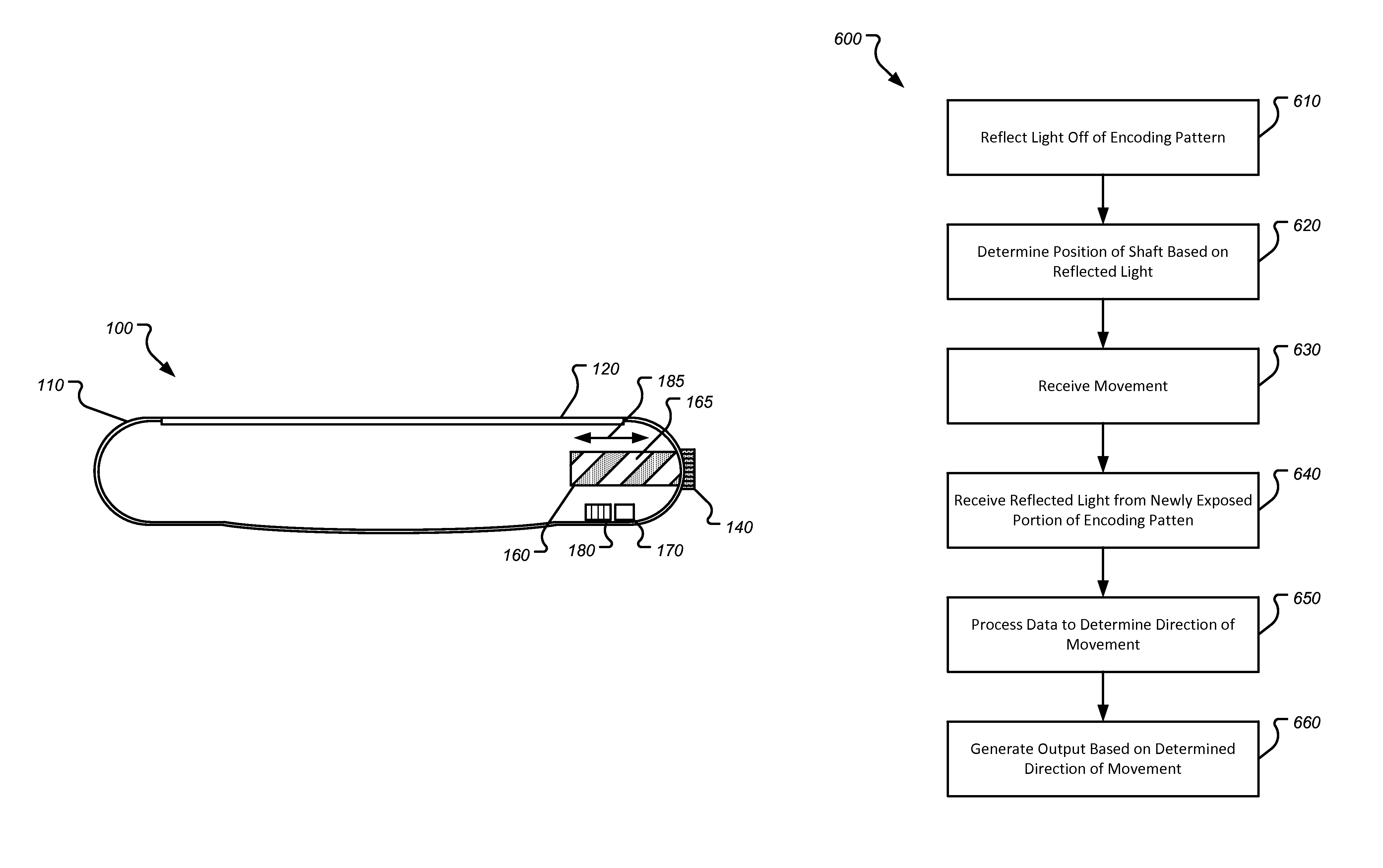
FIG. 1B illustrates a cross-sectional view of the electronic device of FIG. 1A according to one or more embodiments of the present disclosure;
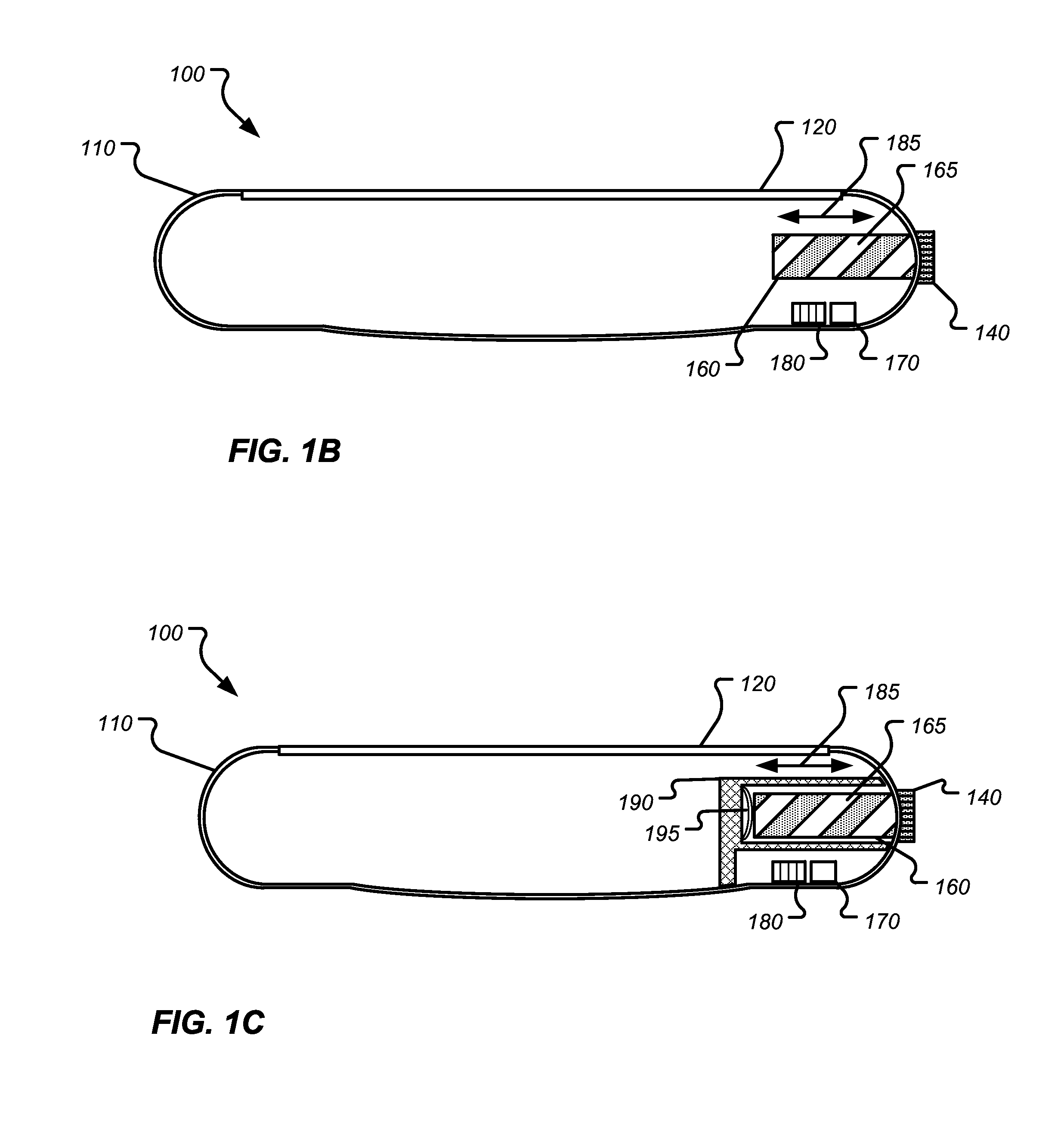
FIG. 1C illustrates a cross-sectional view of the electronic device of FIG. 1A according to an alternate embodiment of the present disclosure
FIGS. 2A-2C illustrate exemplary encoding patterns of an optical encoder according to one or more embodiments of the present disclosure;
FIG. 3 illustrates an exemplary segmented photodiode array according to one or more embodiments of the present disclosure;
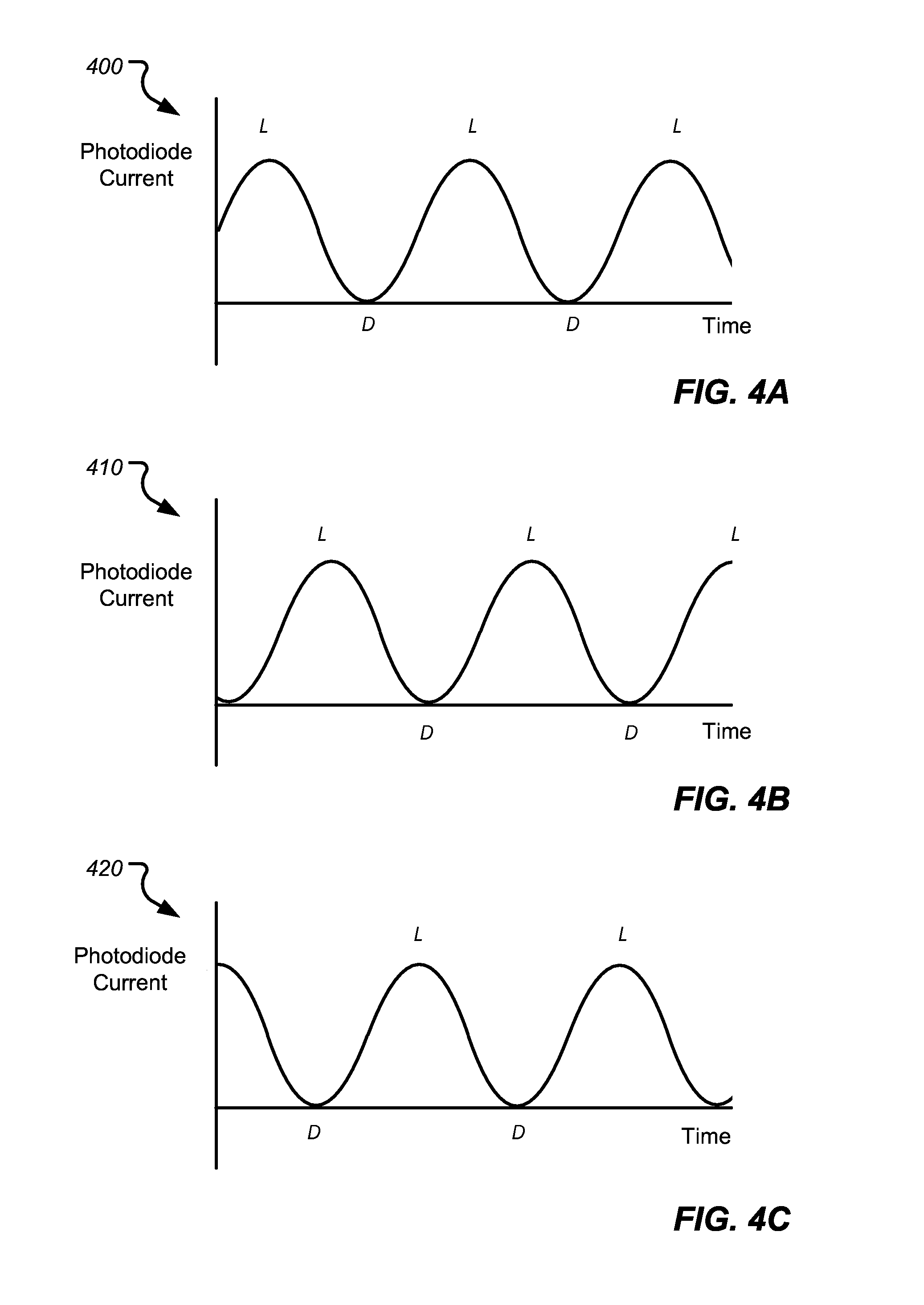
FIGS. 4A-4C illustrate exemplary current output graphs of a photodiode array according to embodiments of the present disclosure;
FIGS. 5A-5B illustrate an optical encoder having components of an optical sensor according to one or more embodiments of the present disclosure; and
FIG. 6 illustrates a method for detecting movement of a component of an electronic device according to one or more embodiments of the present disclosure.
DETAILED DESCRIPTION
Various embodiments are described more fully below with reference to the accompanying drawings, which form a part hereof, and which show specific exemplary embodiments. However, embodiments may be implemented in many different forms and should not be construed as limited to the embodiments set forth herein; rather, these embodiments are provided so that this disclosure will be thorough and complete, and will fully convey the scope of the embodiments to those skilled in the art. The following detailed description is, therefore, not to be taken in a limiting sense.
In some electronic devices, one or more components of the electronic device may be configured to move in a variety of directions. Further, each direction in the variety of directions may have a specific purpose or cause a specific outcome. For example, a crown of a time keeping device may be configured to rotate clockwise and counter-clockwise manner in order to move hands or dials that are displayed or otherwise present on a face of the time keeping device. In addition, the crown may also be configured to move linearly from a first position to a second position. For example, the crown may be pressed inward or pulled outward to accomplish a specified task or perform a particular function.
In the examples described above a single optical encoder may be used to detect both the rotational movement of the crown as well as linear movement of the crown. More specifically, embodiments of the present disclosure describe an optical encoder that detects rotational movement, rotational direction and/or rotational speed of a component of the electronic device as well as linear movement and speed of the component of the electronic device. Once the movement has been determined, this information may be used to output or change information and images that are presented on a display or user interface of the electronic device.
As will be explained below, the optical encoder of the present disclosure includes a light source, a photodiode array, and a shaft. However, unlike typical optical encoders, the optical encoder of the present disclosure utilizes an encoding pattern disposed directly on the shaft. For example, the encoding pattern includes a number of light and dark markings or stripes that are axially disposed and radially disposed along the shaft. Each stripe or combination of stripes on the shaft may be used to identify a position of the shaft.
For example, as light is emitted from the light source and reflected off of the shaft into the photodiode array, a position, rotation, rotation direction and rotation speed of movement of the shaft may be determined. Once the rotation direction and speed are determined, output, images and other information that are presented on the display or user interface of the electronic device may be updated.
In other embodiments, the shape or form of the shaft of the encoder may be used to determine a position linear movement and direction, linear speed, rotational movement, rotational direction rotation speed of the shaft. For example, the shaft may be fluted or have a number of channels that cause the light to be reflected in a number of different directions. Accordingly, a diffractive pattern may be used to determine each of the movements described above.
FIG. 1A illustrates an exemplary electronic device 100 according to one or more embodiments of the present disclosure. In certain embodiments, the electronic device 100 may be a portable computing device. Such examples include cell phones, smart phones, tablet computers, laptop computers, time-keeping devices, computerized glasses and other wearable devices navigation devices, sports devices, accessory devices, health-monitoring devices, medical devices and the like. In one example, and as shown in FIG. 1, the electronic device 100 may be a wearable electronic device. The electronic device 100 may include a housing 110 as well as a display 120, a button 130 (or other input mechanism) and a crown 140.
In many examples, the wearable device, such as is depicted in FIG. 1A, may include a processor coupled with or in communication with a memory, one or more communication interfaces, output devices such as displays and speakers, and one or more additional input devices such as buttons, dials, microphones, or touch-based interfaces. The communication interface(s) can provide electronic communications between the communications device and any external communication network, device or platform, such as but not limited to wireless interfaces, Bluetooth interfaces, Near Field Communication interfaces, infrared interfaces, USB interfaces, Wi-Fi interfaces, TCP/IP interfaces, network communications interfaces, or any conventional communication interfaces. The wearable electronic device 100 may provide information regarding time, health, statuses or externally connected or communicating devices and/or software executing on such devices, messages, video, operating commands, and so forth (and may receive any of the foregoing from an external device), in addition to communications.
In embodiments, the display 120 of the electronic device 100 may be a touch-sensitive display having an input area. The input area may cover the entire display 120 or substantially all of the display 120. In another embodiment, the input area may cover only a portion of the display 120.
The display 120 is configured to output a user interface that displays information about the electronic device 100 as well as other information that is stored in a memory of the electronic device 100. For example, the user interface may present information corresponding to one or more applications that are being executed on the electronic device 100. Such applications may include a time keeping application, an email application, a phone application, a calendaring application, a game application and the like.
In embodiments, the button 130 or the crown 140 may be used to select, adjust or change various images that are output on the display 120. For example, if the display 120 of the electronic device 100 is displaying a time keeping application, the crown 140 may be rotated in either direction to change or adjust the position of the hands or the digits that are displayed for the time keeping application. In other embodiments, the crown 140 may be rotated to move a cursor or other type of selection mechanism from a first displayed location to a second displayed location in order to select an icon or move the selection mechanism between various icons that are output on the display 120. Likewise, the crown may be pulled, pushed or pressed to provide another input to the device 100.
Although not shown in FIG. 1A, the electronic device 100 may also include various additional components that assist in the overall operation of the device. For example, the electronic device 100 may include a sensor, a microphone, a processor, a memory, and the like. Further, the crown 140 and the button 130 may interact with one or more of the components listed to facilitate operation of the electronic device 100.
The electronic device 100 may also include a band 150 that may be used to secure or attach the electronic device 100 to a user. Other attachment mechanisms, such as, for example, a strap, a lanyard or other such attachment mechanism may also be used.
In certain embodiments, electronic device 100 may also include a keyboard or other input mechanism. Additionally, the electronic device 100 may include one or more components that enable the electronic device 100 to connect to the Internet and/or access one or more remote databases or storage devices. The electronic device 100 may also enable communication over wireless media such as acoustic, radio frequency (RF), infrared, and other wireless media mediums. Such communication channels may enable the electronic device 100 to remotely connect and communicate with one or more additional devices such as, for example, a laptop computer, tablet computer, mobile telephone, personal digital assistant, portable music player, speakers and/or headphones and the like.
FIG. 1B and FIG. 1C illustrate cross-sectional views of the electronic device 100 of FIG. 1A according to one or more embodiments of the present disclosure. Referring to FIG. 1B, the electronic device 100 includes an optical encoder that consists of a shaft 160, a light source 170 and a photodiode array 180. Although a photodiode array is specifically mentioned, embodiments disclosed herein may use various types of sensors that are arranged in various configurations for detecting the movement described herein. For example, the movement of the shaft 160 may be detected by an image sensor, a light sensor such as a CMOS light sensor or imager, a photovoltaic cell or system, photo resistive component, a laser scanner and the like.
The optical encoder is used to determine positional data of the crown 140. More specifically, the optical encoder may be used to detect rotational and translational movement of the crown 140 including the direction of each of the movements, the speed of each of the movements and so on. The movement may be rotational movement, translational movement, angular movement, and various combinations. The optical encoder may also be used to detect the degree of the change of rotation of the crown 140 and/or the angle of rotation of the crown 140 as well as the speed and the direction of the rotation of the crown 140. Once the movement data of the crown 140 is determined, one or more graphics, images or icons on the display 120 of the electronic device 100 may be updated or altered accordingly.
For example, and continuing with the time keeping application example discussed above, the crown 140 may be rotated in a clockwise manner in order to change the displayed time. The optical encoder of the present disclosure will detect the original starting position of the crown 140, the rotational movement of the crown 140 in the clockwise direction, and will also detect the speed at which the crown 140 is being rotated. As a result, the displayed hands of the time keeping application may rotate or otherwise move in a similar direction and speed.
In another example, the crown 140 of the electronic device may be actuated in a translational manner such as shown by arrow 185. For example, the crown 140 may be pressed inward toward the housing 110 to select a displayed option. In another example, the crown 140 may be pulled outward to perform a particular function. In still yet another example, the crown may be actuated in a translational manner and in a rotational manner simultaneously or substantially simultaneously. Regardless of the movement, the optical encoder disclosed herein may detect the movement and output or change displayed data accordingly.
Referring back to FIG. 1B, the optical encoder may include a shaft 160. The shaft 160 may be coupled to the crown 140. In another embodiment the shaft 160 may be an extension of the crown 140. That is, the crown 140 and the shaft 160 may be manufactured from a single piece. As the shaft 160 is coupled to, or is otherwise a part of the crown 140, as the crown 140 rotates or moves in a particular direction and at a particular speed, the shaft 160 also rotates or moves in the same direction and with the same speed.
The shaft 160 of the optical encoder includes an encoding pattern 165. As discussed, the encoding pattern 165 is used to determine positional information about the shaft 160 including translational movement, rotational movement, angular displacement as well as movement speed. The encoding pattern 165 may include a plurality of light and dark stripes such as shown in FIG. 1B.
In certain embodiments, the encoding pattern 165 may have an axial component and a radial component. For example, the encoding pattern 165 may include light and dark stripes arranged in an angled configuration 200 such as shown in FIG. 2A, a square wave configuration 210 such as shown in FIG. 2B, a saw-tooth configuration 220 such as shown in FIG. 2C and so on. Although specific shapes and patterns are mentioned, the encoding pattern 165 may also be arranged in a sine wave and various other patterns having both an axial component and a radial component.
Further, although light stripes and dark stripes are specifically mentioned and shown in the figures, the encoding pattern 165 may consist of various types of stripes having various shades or colors that provide surface contrasts. For example, the encoding pattern may include a stripe or marking that has a high reflective surface and another stripe that has a low reflective surface regardless of the color or shading of the stripes or markings. In another embodiment, a first stripe or portion of the first stripe of the encoding pattern may cause specular reflection while a second stripe or a portion of the second stripe of the encoding pattern 165 may cause diffuse reflection. When the reflected light is received by the photodiode array 180, a determination may be made as to the position and movement of the shaft such as described below. In embodiments where a holographic or diffractive pattern is used, the light from the light source will diffract from the shaft. Based on the diffracted light, the photodiode array 180 may determine the position, movement and direction of movement and type of the shaft.
The stripes of the encoding pattern 165 may extend both axially and radially along the shaft 160. The stripes may extend along the entire length of the shaft 160 or partially along a length of the shaft. In addition, the encoding pattern 165 may also be disposed around the entire circumference of the shaft 160. In other embodiments, the encoding pattern may include a radial component. In yet other embodiments, the encoding pattern may have both a radial component and an axial component. For example, the encoding pattern may extend axially along the shaft 160 for a first distance, then extend radially across the shaft 160 for a second distance, extend axially along the shaft 160 for a third distance and so on. The first, second and third distances may all be different distances, similar distances or substantially similar distances. Further, each of the first, second and third distances may have the same width or different widths.
In another embodiment, the encoding pattern 165 may be disposed only on certain areas of the shaft 160. For example, if a shaft 160 was configured to have partial rotational movement about an axis in a given direction (instead of full rotational movement about the axis such as described herein), the encoding pattern 165 may only be disposed on a portion of the shaft 160 that would be visible to the photodiode array 180 as the shaft 160 is moved in a rotational direction and/or a translational direction.
The light and dark stripes of the encoding pattern 165 may alternate between a light stripe and a dark stripe. In another embodiment, the light stripes and the dark stripes of the encoding pattern 165 may be arranged in a particular pattern or order. In such embodiments, each section of the pattern may indicate a position of the shaft 160.
In another example, the stripes of the encoding pattern 165 may have varying widths. The varying widths of each stripe may provide a pattern that indicates a position of the shaft 160. For example, a stripe having a first width may indicate that the shaft 160 is in a first position while a stripe having a second width may indicate the shaft 160 is in a second position. In still yet another example, the different widths of each of the strips may be used to determine linear movement of the shaft 160 as well as rotational movement of the shaft 160.
The stripes of the encoding pattern 200 may also be arranged in different patterns. For example, the stripes of the encoding pattern 200 may arranged in a QR code, a bar code or other such pattern that may be used to determine a rotational, translational, or angular movement of the shaft 160 as well as the movement speed of the shaft 160.
Referring back to FIG. 1B, the optical encoder of the present disclosure also includes a photodiode array 180. The photodiode array 180 may be separated into a number of quadrants or otherwise divided into various sections. Each quadrant of the photodiode array 180 is configured to receive light that is reflected off of the shaft 160. Specifically, the photodiode array 180 is configured to receive light of different intensity values based on whether the light has been reflected off of the encoding pattern and in a direction toward to photodiode array in a diffusive manner, in a specular manner or a combination thereof. The intensity values of the light that is received may then be compared with an intensity value of light received at a previous time to determine movement direction, speed and the like.
For example, the photodiode array 180 may receive light that is reflected off of the encoding pattern 165. Specifically, as light from the light source 170 hits the various stripes of the encoding pattern 165, the light is reflected off of the light stripes in a specular manner and reflected off of the dark stripes in a diffusive manner. The various intensities of the reflected light are then received by the photodiode array 180 which then converts the reflected light into an output current.
Thus, the higher the output current from the photodiode, the more the light stripe, or the reflective stripe, is seen by the quadrants in the photodiode array 180 (or seen by a particular photodiode of the photodiode array 180). Likewise, the smaller the output current, the more the dark stripe, or non-reflective surface, is seen by the photodiode array 180 (or seen by a particular photodiode or quadrant of the photodiode array 180).
Based on the above, rotational and translational movement of the shaft 160 and ultimately the crown 140 may be determined. For example, rotational data may be derived from analyzing the outputs of the photodiodes in the photodiode array 180 across various sample frames. The variance of the outputs in a given time between the sample frames is related to the motion or rotational direction of the stripes of the encoding pattern 180 and ultimately the shaft 160.
Referring to FIG. 3, FIG. 3 illustrates an exemplary segmented photodiode array 300 according to embodiments of the present disclosure. The photodiode array 300 may be similar to the photodiode arrays disclosed herein. For example, photodiode array 300 may be similar to photodiode array 180 described above with respect to FIG. 1B and FIG. 1C or may be similar to photodiode array 530 described below with respect to FIG. 5A and FIG. 5B.
As shown in FIG. 3, the photodiode array 300 may be segmented into various quadrants such, as, for example, quadrant A, quadrant B, quadrant C and quadrant D. Although the photodiode array 300 is shown in various segments, the photodiode array 300 may be arranged in any two dimensional pattern (either segmented or not) that may receive light reflected off of an optical encoder as the optical encoder moves in a translational manner and a rotational manner.
Light from the light source is reflected off of an encoding pattern and received by each quadrant. Values of current received by each quadrant may then be combined and analyzed to determine translational and/or rotational movement of an encoding pattern. Specifically, a change in current values between pairs of quadrants may be compared against previously received values to determine the movement.
For example, current values received in quadrant A and quadrant B (either separately or combined) may be compared with current values received in quadrant C and quadrant D (either separately or combined) over a time period t to detect translational movement of a shaft of an encoder. Likewise, current values received in quadrant A and quadrant C may be compared with current values received in quadrant B and quadrant D over a time period t to detect rotational movement of the shaft of the encoder.
In embodiments, the values received in each quadrant may be compared simultaneously or substantially simultaneously. For example, a determination of translational movement may be determined simultaneously or substantially simultaneously with a determination of rotational movement and vice versa based on output from the photodiode array 300.
In some embodiments, an update to a display may only occur if translational or rotational movement exceeds a threshold. For example, if the photodiode array 300 detects movement in both a translational direction and in a rotational direction simultaneously or substantially simultaneously, a display will be updated only if the movement of the shaft exceeds a given threshold. In another example, a display may only be updated if a change in current output provided by the photodiode array 300 exceeds a particular threshold.
Referring to FIG. 4A-FIG. 4C, FIG. 4A-FIG. 4C show exemplary current output graphs provided by a photodiode array. For example, each graph 400, 410, and 420 represent output provided by a photodiode array as it receives light that is reflected off of an encoding pattern. As discussed above, the sensor that is used to detect movement of the shaft of the optical encoder may be any type of sensor. Thus, the output shown in FIGS. 4A-4C are but one example of output provided by a sensor.
For example, the graph 400 shown in FIG. 4A may represent output of a photodiode array over a time t. In a subsequent time period, the output of the photodiode array may look like the output provided by graph 410 of FIG. 4B. When compared with the output of the graph 400 of FIG. 4A, it can be determined that the shaft of the encoder is rotating in a particular direction or that the shaft of the encoder has moved in a translational direction (e.g., pushed inward). Similarly, when the output of graph 420 shown in FIG. 4C is compared with the output of graph 400, it can be determined that the shaft of the encoder is rotating in another direction or is moving in another translational direction (e.g., pulled outward). More specifically, as the photodiodes in the photodiode array take multiple sequential samples and compare the samples with at least one previous sample, rotational and translational movement is able to be determined based on the current output of the photodiode array.
In addition to the rotational information, the current output from the photodiode array may be used to determine a speed at which the shaft is rotating or moving. In embodiments, the speed of the movement of the shaft is determined based on how quickly the pattern of reflected light changes. Once the movement direction and speed are determined, output on a display of the electronic device may be adjusted accordingly. In addition, the output provided by the photodiode array may be used to detect the angular rotation of the shaft in a similar manner.
Referring back to FIG. 1B, the light source 170 of the electronic device 100 may be any type of emitter that provides a light that can be reflected off of the shaft 160 to be received by the photodiode array 180. For example, the light source 170 may be an LED, an infrared light such as, for example an infrared LED, a linear light source, a laser diode, a light bulb and the like.
In embodiments when the light source 170 is an infrared light source, the encoding pattern 165 disposed on the shaft 160 may be invisible to the human eye but the overall movement determination may operate as described above. For example, a first set of stripes of the encoding pattern 165 may be IR-absorptive and a second set of stripes of the encoding pattern 165 may be IR-reflective. The photodiode array may receive the IR-reflective light when the IR-reflective stripe is shown and less light as the shaft turns. Accordingly, a determination of rotational movement may be made as described above.
In embodiments, the light source 170 and the photodiode 180 are axially aligned with respect to the shaft 160. In another embodiment, the light source 170 and the photodiode 180 may be radially aligned with respect to the shaft 160. Although specific alignments are disclosed, in certain embodiments the light source 170 and the photodiode array 180 may be aligned with the shaft 160 in any suitable manner so long as light is emitted from the light source 170 is reflected off of the encoding pattern 165 on the shaft 160 and received by the photodiode array 180.
Depending on the use of the shaft 160, the length of the shaft 160 may vary between embodiments. For example, in some embodiments, the length of the shaft 160 may extend along a length or width of the housing 110. In another embodiment, the shaft 160 may have a length that is substantially less than a length or width of the housing 110.
In addition to the above, the distance in a z direction between the shaft 160 and the light source 170 and the photodiode array 180 may also vary. Generally, it should be noted that, as the z distance between the shaft 160 and the light source 170 and the photodiode 180 increases, the pattern of light reflected off of the shaft 160 increases in size. Specifically, the number of samples in a given time frame decreases. Likewise, as the z distance between the shaft 160 and the light source 170 and the photodiode array 180 decreases, the pattern of light reflected off of the shaft 160 decreases in size. More specifically, the number of samples in a given time frame increases. As the number of samples increase, the rotational direction and the rotation speed of the shaft may be better determined.
FIG. 1C illustrates a cross-sectional view of the electronic device 100 according to another embodiment of the present disclosure. As shown in FIG. 1C, the electronic device 100 includes similar components to those described above with respect to FIG. 1B. For example, the electronic device 100 includes an optical encoder that consists of a shaft 160, a light source 170 and a photodiode array 180. The shaft 160 includes an encoding pattern 165 that has both axial components and radial components. Further the optical encoder may be used to detect rotational movement and translational movement (as shown by arrow 185).
In addition to the components described above with respect to FIG. 1B, the electronic device 100 shown in FIG. 1C includes a sealing portion 190 and a button 195. Referring to the sealing portion 190, the sealing portion 190 may be used to protect the encoder wheel from outside elements that may cause damage or otherwise corrode the encoding pattern 165 or the shaft 160. In embodiments, the sealing portion 190 may be used to fully seal all of the components of the optical encoder including the photodiode array 180 and the light source 170.
The sealing portion 190 may be made of glass, plastic, sapphire or other transmissive material. In embodiments, only the portion of the sealing portion 190 through which light from the light source 170 passes is transmissive. In other embodiments, all, or substantially all of the sealing portion 190 may be made from the same material. Further, the sealing portion 190 may be rounded, rectilinear, square and so on.
In embodiments, the space between the sealing portion 190 and the rest of the components of the optical encoder may be filled with air, inert gas, a liquid (e.g., an oil lubricant) or may be a vacuum space. Use of such materials may prevent or help to prevent rust and/or reduce wear and tear on the various components of the optical sensor.
The sealing portion 190 may also include a button 195. In embodiments, the button 195 may be a mechanical tac switch that creates a switch click but contains no electronics. Thus, when a user pushes on the crown 140 of the electronic device, the user feels actuation of a button. However, translational movement of the optical encoder such as described above, provides the data regarding the "button press." In other embodiments, button 195 may include all electronics of a button and provide signals when actuated.
FIG. 5A-FIG. 5B illustrate an optical encoder 500 according to one or more embodiments of the present disclosure. In embodiments, the optical encoder 500 may be similar to the optical encoder shown and described with respect to FIG. 1B and FIG. 1C.
As shown in FIG. 5A, the optical encoder 500 includes a shaft 510, a light source 540 and a photodiode array 530. The shaft 510 includes an encoding pattern 515. The encoding pattern 515 may include a plurality of different colored stripes or shaded stripes that have an axial component and a radial component. For example, as shown in FIG. 5A, the stripes of the encoding pattern 515 may wrap around a circumference of the shaft 510 along a length of the shaft 515.
In other embodiments, the stripes of the encoding pattern may alternate in color, width, length and the like. For example, a first stripe of the encoding pattern 515 may be in a first color, a second stripe of the encoding pattern 515 may be in a second color and a third stripe of the encoding pattern 515 may be in a third color. As different colors may be used, the photodiode array 550 may be color-sensitive. Accordingly the change in color in the encoding pattern 515 as the shaft rotates about it axis may be used to determine rotational and translational movement of the shaft 510 as well as movement speed of the shaft 510.
In certain embodiments, the stripes of the encoding pattern 515 may be configured to cause specular reflection and diffuse reflection. For example, the light 545 from the light source 540 may be reflected in either or both of a specular manner or in a diffusive manner from the shaft to the photodiode array 530. When the light 545 is received by the photodiode array, a current, based on the intensity of the light, is used to determine a current position of the shaft. When the shaft is moved, the change in light intensity or current that is output from the photodiode array is used to determine translational and/or rotational movement of the shaft 510 such as described above.
Although embodiments shown and described discuss the use of both light and dark stripes in the encoding pattern, in certain embodiments, the entire shaft 510 may be specular (e.g., the entire shaft 510 enables specular reflection). In such embodiments, the shaft 510 may have one or more striations, flutes, channels and the like.
For example, a shaft of an optical encoder may include a plurality of surface forms, such as, for example one or more flutes, channels and the like. The surface forms may include be axially aligned with respect to the shaft, radially aligned with respect to the shaft or a combination thereof. These surface forms may cause light to be reflected from the shaft even if there is no variation in color or reflectance from the shaft. In embodiments, the surface forms may be added to the shaft during the manufacturing process or may be a natural byproduct (or otherwise present) in the shaft due to a machining process.
In embodiments where the surface forms are present, the shape of the one or more surface forms in the shaft may cause the light from a light source to be reflected from the shaft in many different angles and be received by a photodiode array thereby simulating diffusion. In such embodiments, the surface forms may vary in size or have the same or substantially the same size. In other embodiments, the shaft may include surface forms as well as one or more light and/or dark stripes of an encoding pattern such as described above. As such, both features may then be used in conjunction to determine rotational and/or linear movement and speed such as described above.
Referring back to FIG. 5A, the optical encoder 500 may include a light source 540 and a photodiode array 530. In embodiments, the light source 540 may be axially aligned or radially aligned with the photodiode array 530 or with the shaft 510.
The photodiode array 530 may be segmented into quadrants such as described above. In another embodiment, the photodiode array 530 may be a two dimensional array having a n rows and m columns. For example as shown in FIG. 5A, the photodiode array 530 may be a four by two photodiode array. However, the number of photodiodes in the two dimensional photodiode array may increase or decrease depending on the size of the collection area of each of the photodiodes. For example, an accurate rotational or linear movement of the shaft 510 may be collected from an array of two photodiodes. In other embodiments, eight or more photodiodes may be required. In another embodiment, multiple arrays of photodiodes may be used. Further, each of photodiode arrays may be arranged in various alignments and positions with respect to the shaft 510.
In another embodiment, the photodiode array 530 may be arranged such as shown in FIG. 5B. As shown, at least one portion of the photodiode array is axially aligned with the respect to the shaft 510 or more specifically, at least one stripe of the optical encoder is axially aligned with respect to the photodiode array 530. In such arrangement, a first portion of the photodiode array 530 may be used to determine rotational movement while a second portion of the photodiode array may be used to determine translational movement.
In yet another embodiment, a portion of the photodiode array 530 may be offset from the encoder in a push or a pull direction. Thus, any change in light intensity received by the offset portion of the photodiode array would indicate translational actuation of the of the shaft 510.
FIG. 6 illustrates a method 600 for collecting and determining movement of a shaft of an optical encoder according to one or more embodiments of the present disclosure. In embodiments, the method 600 may be used to determine rotational movement of the shaft, angular movement of the shaft, translational movement of the shaft as well as a speed of movement of the shaft. Further, the method 600 described below may be used with the embodiments shown and described above with respect to FIG. 1A through FIG. 5B.
The method 600 begins by causing light from a light source to be reflected off of an encoding pattern that is disposed on a shaft of an optical encoder. The encoding pattern disposed on the shaft may include a plurality of light and dark stripes that have one or both of an axial component and a radial component.
In another embodiment, the shaft of the optical encoder may include one or more surface components. In such embodiments, the surface components may be used to reflect light in a variety of different directions. The surface components may be used in conjunction with the light and dark markings of the encoding pattern. In alternative embodiments, the surface components may be used without the need of either one or both of the light markings of the encoding pattern or the dark markings of the encoding pattern.
In operation 620, the light that is reflected off of the encoding pattern is received by a photodiode array. More specifically, light that is reflected off of the encoding pattern is received by various quadrants of the photodiode array. When the photodiode array receives the reflected light, an initial position of the shaft may be determined. Specifically, as light is reflected from the encoding pattern and received by the quadrants of the photodiode array, pairs of quadrants of the photodiode array output a current which represents the amount of light and dark stripes that are in view of the respective quadrants of the photodiode array. This output current may then be used to represent a position of the shaft at a time t.
Flow then proceeds to operation 630 in which movement of the shaft is received. In embodiment, the movement may be rotational movement, translational movement, angular movement or combinations thereof. For example a crown of an electronic device may be rotated to change an output on a display such as described above. In another embodiment, the crown may be pushed inward or pulled outward.
Flow then proceeds to operation 640 in which light from the newly exposed portion of the encoding pattern is received by the quadrants of the photodiode array. When the newly reflected light is received, the quadrants of the photodiode array output a current based on the intensity of the reflected light.
Once the reflected light from the newly exposed encoding pattern is received, operation 650 provides that the data output by the quadrants of the photodiode array is analyzed to determine a direction of movement of the shaft. In embodiments, the speed of the movement of the shaft may also be determined.
Specifically, operation 650 provides that data output by specific quadrants of the photodiode array from operation 620 above may be compared against data output by the photodiode array from operation 640. For example, the comparison of light intensity received by quadrants A and B (FIG. 3) versus the light intensity received by quadrants C and D at a first time is compared with light intensity received by quadrants A and B versus quadrants C and D at a second time to determine whether any translational movement occurred. Likewise, the comparison of light intensity received by quadrants A and C (FIG. 3) versus light intensity received by quadrants B and D at a first time is compared against light intensity received by quadrants A and C versus light intensity received by quadrants B and D at a second time to determine if rotational movement has occurred.
Further, operation 650 may be used to determine a speed of rotation of the shaft. For example, as the photodiode array outputs the detected change in current, the speed of the change may also be monitored. The change in speed may then be used to determine the overall speed of the movement of the shaft.
In operation 660, output is generated based on the determined direction of the movement of the shaft. For example, as a crown of an electronic device is rotated or otherwise moves, one or more icons or images a display of the electronic device may need to be updated accordingly. For example, if the display of the electronic device is displaying a time keeping application, the crown of the electronic device may be rotated in either direction to change or adjust the position of the hands that are displayed by the time keeping application. Specifically, the hands that are displayed by the time keeping application may move in the direction and speed indicated by the determined movement and speed of the shaft such as described above. If translational movement is determined, a specific functionality (e.g., selection of an icon) may be performed.
Although embodiments have been described above with respect to a rotational and translational movement of a shaft of an electronic device, embodiments of the present disclosure are not so limited. For example, the crown of the electronic device shown with respect to FIG. 1A could be replaced by a keycap for a keyboard. Thus, each key of the keyboard may be optically encoded for translational movement or other types of movement. In other embodiments, the optical encoder disclosed herein could be used with a button a sliding switch and the like.
Embodiments of the present disclosure are described above with reference to block diagrams and operational illustrations of methods and the like. The operations described may occur out of the order as shown in any of the figures. Additionally, one or more operations may be removed or executed substantially concurrently. For example, two blocks shown in succession may be executed substantially concurrently. Additionally, the blocks may be executed in the reverse order.
The description and illustration of one or more embodiments provided in this disclosure are not intended to limit or restrict the scope of the present disclosure as claimed. The embodiments, examples, and details provided in this disclosure are considered sufficient to convey possession and enable others to make and use the best mode of the claimed embodiments. Additionally, the claimed embodiments should not be construed as being limited to any embodiment, example, or detail provided above. Regardless of whether shown and described in combination or separately, the various features, including structural features and methodological features, are intended to be selectively included or omitted to produce an embodiment with a particular set of features. Having been provided with the description and illustration of the present application, one skilled in the art may envision variations, modifications, and alternate embodiments falling within the spirit of the broader aspects of the embodiments described herein that do not depart from the broader scope of the claimed embodiments.
* * * * *
References
-
deskthority.net/keyboards-f2/optical-switch-keyboards-t1474.html
-
sooperarticles.com/health-fitness-articles/children-health-articles/how-vesag-helps-kids-women-visitors-218542.html
-
mhealth.vesag.com/?m=201012
-
virtualpressoffice.com/eventsSubmenu.do?page=exhibitorPage&showId=1551&companyId=5394
-
amazon.com/iPhone-Universal-Remote-Control-Accessory/dp/tech-data/B0038Z4
-
vyasa-kaaranam-ketkadey.blogspot.com/2011/03/vesag-wrist-watch-for-dementia-care.html
-
-
24-7pressrelease.com/press-release/vyzin-unveiled-personal-emergency-response-system-pers-with-remote-health-monitoring-that-can-be-used-for-entire-family-219317.php
-
ip.com
-
medicineandtechnology.com/2010/08/2010-mhealth-summit-emerges-as-major.html
-
sensetekgroup.com/2010/11/29/wireless-health-monitoring-system
-
ezinearticles.com/?How-Vesag-Helps-People-Who-Want-to-Be-There?&id-5423873
-
itnewsafrica.com/2010/11/mobile-innovation-helps-dementia-andalzheimer%E2%80%99s-patients
-
whatafuture.com/2014/02/28/google-smartwatch/#sthash.Yk35cDXK.dpbs
D00000
D00001
D00002
D00003
D00004
D00005
D00006
D00007
D00008
XML
uspto.report is an independent third-party trademark research tool that is not affiliated, endorsed, or sponsored by the United States Patent and Trademark Office (USPTO) or any other governmental organization. The information provided by uspto.report is based on publicly available data at the time of writing and is intended for informational purposes only.
While we strive to provide accurate and up-to-date information, we do not guarantee the accuracy, completeness, reliability, or suitability of the information displayed on this site. The use of this site is at your own risk. Any reliance you place on such information is therefore strictly at your own risk.
All official trademark data, including owner information, should be verified by visiting the official USPTO website at www.uspto.gov. This site is not intended to replace professional legal advice and should not be used as a substitute for consulting with a legal professional who is knowledgeable about trademark law.