Intraocular lens inserter
Auld Ja
U.S. patent number 10,188,506 [Application Number 14/679,921] was granted by the patent office on 2019-01-29 for intraocular lens inserter. This patent grant is currently assigned to Alcon Pharmaceuticals, Ltd.. The grantee listed for this patent is ALCON PHARMACEUTICALS LTD.. Invention is credited to Jack R. Auld.


| United States Patent | 10,188,506 |
| Auld | January 29, 2019 |
Intraocular lens inserter
Abstract
An intraocular lens inserter can include an energy storage portion, an actuator portion, and a lens support portion. The energy storage portion can include a compressible energy storage device, such as a compressible fluid, springs, and other devices. The inserter can include an actuator portion operating with a substantially incompressible fluid, such as liquids or other noncompressible fluids. The actuator can be configured to provide an operator with control over the release of energy from the energy storage portion so as to move a plunger for the discharge of a lens from an intraocular lens cartridge.
| Inventors: | Auld; Jack R. (Lake Forest, CA) | ||||||||||
|---|---|---|---|---|---|---|---|---|---|---|---|
| Applicant: |
|
||||||||||
| Assignee: | Alcon Pharmaceuticals, Ltd.
(Case Postale, Fribourg, CH) |
||||||||||
| Family ID: | 49712566 | ||||||||||
| Appl. No.: | 14/679,921 | ||||||||||
| Filed: | April 6, 2015 |
Prior Publication Data
| Document Identifier | Publication Date | |
|---|---|---|
| US 20160067036 A1 | Mar 10, 2016 | |
Related U.S. Patent Documents
| Application Number | Filing Date | Patent Number | Issue Date | ||
|---|---|---|---|---|---|
| 14291743 | Apr 7, 2015 | 8998983 | |||
| PCT/US2013/044183 | Jun 4, 2013 | ||||
| 61655255 | Jun 4, 2012 | ||||
| Current U.S. Class: | 1/1 |
| Current CPC Class: | A61F 2/1678 (20130101); A61F 2/167 (20130101); A61F 2/1662 (20130101); A61F 9/007 (20130101) |
| Current International Class: | A61F 2/16 (20060101); A61F 9/007 (20060101) |
| Field of Search: | ;606/107-108 ;623/6.11-6.13 ;604/8-10,57,59-60,187 |
References Cited [Referenced By]
U.S. Patent Documents
| 2547099 | April 1951 | Smoot |
| 4429421 | February 1984 | Levy |
| 4573998 | March 1986 | Mazzocco |
| 4615703 | October 1986 | Callahan et al. |
| 4619256 | October 1986 | Horn |
| 4634423 | January 1987 | Bailey, Jr. |
| 4699140 | October 1987 | Holmes et al. |
| 4715373 | December 1987 | Mazzocco et al. |
| 4726367 | February 1988 | Shoemaker |
| 4747404 | May 1988 | Jampel et al. |
| 4763650 | August 1988 | Hauser |
| 4765329 | August 1988 | Cumming et al. |
| 4822360 | April 1989 | Deacon |
| 4844065 | July 1989 | Faulkner |
| 4844093 | July 1989 | Jampel et al. |
| 4852566 | August 1989 | Callahan et al. |
| 4862885 | September 1989 | Cumming |
| 4880000 | November 1989 | Holmes et al. |
| 4906247 | March 1990 | Fritch |
| 4919130 | April 1990 | Stoy et al. |
| 4934363 | June 1990 | Smith et al. |
| 5007913 | April 1991 | Dulebohn et al. |
| 5064413 | November 1991 | McKinnon |
| 5066297 | November 1991 | Cumming |
| 5098439 | March 1992 | Hill et al. |
| 5123905 | June 1992 | Kelman |
| 5222972 | January 1993 | Hill et al. |
| 5190552 | March 1993 | Kelman |
| 5304182 | April 1994 | Rheinish et al. |
| 5354333 | October 1994 | Kammann et al. |
| 5496328 | March 1996 | Nakajima et al. |
| 5562676 | October 1996 | Brady et al. |
| 5582613 | December 1996 | Brady et al. |
| 5582614 | December 1996 | Feingold |
| 5607433 | March 1997 | Polla et al. |
| 5616148 | April 1997 | Eagles et al. |
| 5629577 | May 1997 | Polla et al. |
| 5630821 | May 1997 | Klaas |
| 5643275 | July 1997 | Blake |
| 5643276 | July 1997 | Zaleski |
| 5693057 | December 1997 | Dusek |
| 5716364 | February 1998 | Makker et al. |
| 5772666 | June 1998 | Feingold et al. |
| 5772667 | June 1998 | Blake |
| 5776138 | July 1998 | Vidal et al. |
| 5800441 | September 1998 | Polla et al. |
| 5803925 | September 1998 | Yang et al. |
| 5807400 | September 1998 | Chambers et al. |
| 5810833 | September 1998 | Brady et al. |
| 5860984 | January 1999 | Chambers et al. |
| 5868751 | February 1999 | Feingold |
| 5873879 | February 1999 | Figueroa et al. |
| 5876406 | March 1999 | Wolf et al. |
| 5876407 | March 1999 | Makker et al. |
| 5876440 | March 1999 | Feingold |
| 5921989 | June 1999 | Deacon et al. |
| 5944725 | August 1999 | Cicenas et al. |
| 5947975 | September 1999 | Kikuchi et al. |
| 5947976 | September 1999 | Van Noy et al. |
| 6042587 | March 2000 | Polla et al. |
| 6162230 | December 2000 | Polla et al. |
| 6299618 | October 2001 | Sugiura |
| 6312433 | November 2001 | Butts et al. |
| 6334862 | January 2002 | Vidal et al. |
| 6336932 | January 2002 | Figueroa et al. |
| 6342058 | January 2002 | Portney |
| 6371960 | April 2002 | Heyman et al. |
| 6387101 | May 2002 | Butts et al. |
| 6398789 | June 2002 | Capetan |
| 6428545 | August 2002 | Portney |
| 6468282 | October 2002 | Kikuchi et al. |
| 6491697 | December 2002 | Clark et al. |
| 6500181 | December 2002 | Portney |
| 6500239 | December 2002 | Castellano et al. |
| 6503275 | January 2003 | Cumming |
| 6506195 | January 2003 | Chambers et al. |
| 6537281 | March 2003 | Portney |
| 6537283 | March 2003 | Van Noy |
| 6540754 | April 2003 | Brady |
| 6554839 | April 2003 | Brady |
| 6558395 | May 2003 | Hjertman et al. |
| 6592591 | July 2003 | Polla et al. |
| 6607537 | August 2003 | Binder |
| 6629979 | October 2003 | Feingold et al. |
| 6666871 | December 2003 | Kikuchi et al. |
| 6679891 | January 2004 | Makker et al. |
| 6685740 | February 2004 | Figueroa et al. |
| 6712848 | March 2004 | Wolf et al. |
| 6723104 | April 2004 | Ott |
| 6733507 | May 2004 | McNicholas et al. |
| 6858033 | February 2005 | Kobayashi |
| 6921405 | July 2005 | Feingold et al. |
| 6923815 | August 2005 | Brady et al. |
| 6976989 | December 2005 | Vincent |
| 7025782 | April 2006 | Kobayashi et al. |
| 7033366 | April 2006 | Brady |
| 7037312 | May 2006 | Kikuchi et al. |
| 7037328 | May 2006 | Vincent |
| 7131976 | November 2006 | Kobayashi et al. |
| 7137994 | November 2006 | De Juan, Jr. et al. |
| 7156854 | January 2007 | Brown et al. |
| 7156855 | January 2007 | Oda |
| 7276071 | October 2007 | Lin et al. |
| 7279006 | October 2007 | Vincent |
| 7335209 | February 2008 | Meyer |
| RE40185 | March 2008 | Kikuchi et al. |
| 7348038 | March 2008 | Makker et al. |
| 7422604 | September 2008 | Vaquero et al. |
| 7429263 | September 2008 | Vaquero et al. |
| 7458976 | December 2008 | Peterson et al. |
| 7476229 | January 2009 | Meyer |
| 7476230 | January 2009 | Ohno et al. |
| 7645300 | January 2010 | Tsai |
| 7687097 | March 2010 | Makker et al. |
| 7704258 | April 2010 | Feingold et al. |
| 7717879 | May 2010 | Mansouri |
| 7740607 | June 2010 | Willis et al. |
| 7740636 | June 2010 | Lee et al. |
| 7744603 | June 2010 | Zadno-Azizi et al. |
| 7867240 | January 2011 | Peterson et al. |
| 7892283 | February 2011 | Shepherd |
| 7901414 | March 2011 | Tourrette et al. |
| 7947049 | May 2011 | Vaquero |
| 7988701 | August 2011 | Vaquero et al. |
| 8021423 | September 2011 | Tanaka |
| 8048085 | November 2011 | Peterson et al. |
| 8062360 | November 2011 | Pollock |
| 8080017 | December 2011 | Tanaka |
| 8114095 | February 2012 | Rathert |
| 8123719 | February 2012 | Edwards et al. |
| 8123804 | February 2012 | Tanaka |
| 8142498 | March 2012 | Tsai |
| 8152817 | April 2012 | Tanaka |
| 8216629 | July 2012 | Mentak |
| 8225643 | July 2012 | Abboud et al. |
| 8246631 | August 2012 | Pynson |
| 8252053 | August 2012 | Pynson |
| 8308736 | November 2012 | Boukhny et al. |
| 8308799 | November 2012 | Chen et al. |
| 8500681 | August 2013 | Gonnelli et al. |
| 8574196 | November 2013 | Stammen et al. |
| 8579969 | November 2013 | Zacharias |
| 8617099 | December 2013 | Williamson |
| 8657835 | February 2014 | Boukhny et al. |
| 8668734 | March 2014 | Hildebrand et al. |
| 8721702 | May 2014 | Ramada et al. |
| 8758433 | June 2014 | Cole et al. |
| 8956408 | February 2015 | Smiley et al. |
| 8968396 | March 2015 | Matthews et al. |
| 8998983 | April 2015 | Auld |
| 9228273 | January 2016 | Keszler et al. |
| 9255665 | February 2016 | Brouillette et al. |
| 2001/0007075 | July 2001 | Hjertman et al. |
| 2001/0007942 | July 2001 | Kikuchi et al. |
| 2001/0015593 | August 2001 | Polla et al. |
| 2002/0193803 | December 2002 | Portney |
| 2003/0187455 | October 2003 | Kobayashi et al. |
| 2003/0212406 | November 2003 | Kobayashi et al. |
| 2003/0212407 | November 2003 | Kikuchi et al. |
| 2003/0216745 | November 2003 | Brady et al. |
| 2004/0059343 | March 2004 | Shearer et al. |
| 2004/0127911 | July 2004 | Figueroa et al. |
| 2004/0215207 | October 2004 | Cumming |
| 2004/0267359 | December 2004 | Maker et al. |
| 2005/0033308 | February 2005 | Callahan et al. |
| 2005/0171555 | August 2005 | Tran et al. |
| 2005/0222577 | October 2005 | Vaquero |
| 2005/0267403 | December 2005 | Landau et al. |
| 2005/0283162 | December 2005 | Stratas |
| 2005/0283163 | December 2005 | Portney et al. |
| 2005/0283164 | December 2005 | Wu et al. |
| 2006/0085013 | April 2006 | Dusek et al. |
| 2006/0129125 | June 2006 | Copa et al. |
| 2006/0142780 | June 2006 | Pynson et al. |
| 2006/0142781 | June 2006 | Pynson et al. |
| 2006/0167466 | July 2006 | Dusek |
| 2006/0184181 | August 2006 | Cole et al. |
| 2006/0264971 | November 2006 | Akahoshi |
| 2006/0271063 | November 2006 | Sunada et al. |
| 2006/0287655 | December 2006 | Khuray et al. |
| 2006/0293694 | December 2006 | Futamura |
| 2007/0060925 | March 2007 | Pynson |
| 2007/0112355 | May 2007 | Salahieh et al. |
| 2007/0203502 | August 2007 | Makker et al. |
| 2007/0270881 | November 2007 | Hishinuma et al. |
| 2007/0270945 | November 2007 | Kobayashi et al. |
| 2008/0004610 | January 2008 | Miller et al. |
| 2008/0027460 | January 2008 | Kobayashi |
| 2008/0027461 | January 2008 | Vaquero et al. |
| 2008/0033449 | February 2008 | Cole et al. |
| 2008/0039862 | February 2008 | Tran |
| 2008/0058830 | March 2008 | Cole et al. |
| 2008/0086146 | April 2008 | Ishii et al. |
| 2008/0097459 | April 2008 | Kammerlander et al. |
| 2008/0097460 | April 2008 | Boukhny et al. |
| 2008/0097461 | April 2008 | Boukhny et al. |
| 2008/0114203 | May 2008 | Crank |
| 2008/0119783 | May 2008 | Green |
| 2008/0147080 | June 2008 | Pynson |
| 2008/0147081 | June 2008 | Pynson |
| 2008/0147082 | June 2008 | Pynson |
| 2008/0154361 | June 2008 | Pynson et al. |
| 2008/0171968 | July 2008 | Stout et al. |
| 2008/0208176 | August 2008 | Loh |
| 2008/0255579 | October 2008 | Wollenhaupt et al. |
| 2008/0269770 | October 2008 | Pynson et al. |
| 2009/0005788 | January 2009 | Rathert |
| 2009/0018548 | January 2009 | Charles |
| 2009/0024136 | January 2009 | Martin et al. |
| 2009/0030425 | January 2009 | Smiley et al. |
| 2009/0036898 | February 2009 | Ichinohe et al. |
| 2009/0043313 | February 2009 | Ichinohe et al. |
| 2009/0112222 | April 2009 | Barrows et al. |
| 2009/0198247 | August 2009 | Ben Nun |
| 2009/0204122 | August 2009 | Ichinohe et al. |
| 2009/0234366 | September 2009 | Tsai et al. |
| 2009/0248031 | October 2009 | Ichinohe et al. |
| 2009/0270876 | October 2009 | Hoffmann et al. |
| 2009/0292293 | November 2009 | Bogaert et al. |
| 2009/0318933 | December 2009 | Anderson |
| 2010/0010498 | January 2010 | Biddle et al. |
| 2010/0057095 | March 2010 | Khuray et al. |
| 2010/0076450 | March 2010 | Yoshida et al. |
| 2010/0082037 | April 2010 | Kobayashi et al. |
| 2010/0087832 | April 2010 | Seyboth |
| 2010/0094309 | April 2010 | Boukhny et al. |
| 2010/0106160 | April 2010 | Tsai |
| 2010/0121340 | May 2010 | Downer |
| 2010/0125278 | May 2010 | Wagner |
| 2010/0125279 | May 2010 | Karakelle et al. |
| 2010/0160926 | June 2010 | Artsyukhovich et al. |
| 2010/0161049 | June 2010 | Inoue |
| 2010/0185206 | July 2010 | Ichinohe et al. |
| 2010/0204704 | August 2010 | Davies et al. |
| 2010/0204705 | August 2010 | Brown et al. |
| 2010/0217273 | August 2010 | Someya et al. |
| 2010/0217274 | August 2010 | Lee et al. |
| 2010/0228260 | September 2010 | Callahan et al. |
| 2010/0228261 | September 2010 | Feingold et al. |
| 2010/0256651 | October 2010 | Jani et al. |
| 2010/0280521 | November 2010 | Vaquero et al. |
| 2010/0286704 | November 2010 | Ichinohe et al. |
| 2010/0305577 | December 2010 | Muchhala et al. |
| 2010/0312254 | December 2010 | Downer et al. |
| 2011/0046633 | February 2011 | Pankin et al. |
| 2011/0046634 | February 2011 | Rathert |
| 2011/0046635 | February 2011 | Pankin et al. |
| 2011/0082463 | April 2011 | Inoue |
| 2011/0098717 | April 2011 | Inoue |
| 2011/0144653 | June 2011 | Pankin et al. |
| 2011/0152872 | June 2011 | Seyboth et al. |
| 2011/0152873 | June 2011 | Shepherd |
| 2011/0172676 | July 2011 | Chen |
| 2011/0190777 | August 2011 | Hohl |
| 2011/0213380 | September 2011 | Han |
| 2011/0224677 | September 2011 | Niwa et al. |
| 2011/0245840 | October 2011 | Seyboth et al. |
| 2011/0264101 | October 2011 | Inoue et al. |
| 2011/0264102 | October 2011 | Cole et al. |
| 2011/0264103 | October 2011 | Cole et al. |
| 2011/0270264 | November 2011 | Shoji et al. |
| 2011/0288557 | November 2011 | Kudo et al. |
| 2011/0295264 | December 2011 | Cole et al. |
| 2011/0313425 | December 2011 | Han |
| 2012/0016374 | January 2012 | Han |
| 2012/0016375 | January 2012 | Peterson et al. |
| 2012/0022547 | January 2012 | Hildebrand et al. |
| 2012/0022548 | January 2012 | Zacharias |
| 2012/0071888 | March 2012 | Putallaz et al. |
| 2012/0130390 | May 2012 | Davies et al. |
| 2012/0158007 | June 2012 | Brown et al. |
| 2012/0165824 | June 2012 | Tsai |
| 2012/0245591 | September 2012 | Matthews |
| 2012/0253356 | October 2012 | Niwa et al. |
| 2012/0289969 | November 2012 | Seyboth et al. |
| 2012/0289970 | November 2012 | Pynson |
| 2012/0296264 | November 2012 | Boukhny et al. |
| 2013/0012956 | January 2013 | Mirlay |
| 2013/0035939 | February 2013 | Gilbert et al. |
| 2013/0041382 | February 2013 | Ben Nun |
| 2013/0197531 | August 2013 | Boukhny et al. |
| 2013/0197532 | August 2013 | Boukhny et al. |
| 2013/0281927 | October 2013 | Jennings et al. |
| 2014/0200590 | July 2014 | Chen |
| 2015/0088149 | March 2015 | Auld |
| 2015/0342726 | December 2015 | Deacon |
| 2858485 | Jun 2013 | CA | |||
| 174129 | Mar 1986 | EP | |||
| 0477466 | Apr 1992 | EP | |||
| 0937466 | Aug 1999 | EP | |||
| 1481652 | Nov 2006 | EP | |||
| 1175187 | Jun 2007 | EP | |||
| 1857075 | Nov 2007 | EP | |||
| 1736118 | Dec 2008 | EP | |||
| 2368526 | Sep 2011 | EP | |||
| 1344503 | Oct 2011 | EP | |||
| 2324797 | Feb 2012 | EP | |||
| 2074962 | Mar 2012 | EP | |||
| 1539065 | Dec 2012 | EP | |||
| 1748811 | Dec 2012 | EP | |||
| 2178464 | Aug 2013 | EP | |||
| 2491902 | Jul 2015 | EP | |||
| 2560578 | Jun 2016 | EP | |||
| 2502603 | Oct 2016 | EP | |||
| 3075353 | Oct 2016 | EP | |||
| 3122286 | Feb 2017 | EP | |||
| 3207374 | Sep 1991 | JP | |||
| 2004261263 | Sep 2004 | JP | |||
| 2007215990 | Aug 2007 | JP | |||
| 2008500876 | Jan 2008 | JP | |||
| 2016049321 | Apr 2016 | JP | |||
| 2386423 | Apr 2010 | RU | |||
| 1996037152 | Nov 1996 | WO | |||
| 200164147 | Sep 2001 | WO | |||
| WO 2007-0098622 | Sep 2007 | WO | |||
| WO 2007-0112130 | Oct 2007 | WO | |||
| WO 2010-0028873 | Mar 2010 | WO | |||
| 2011133823 | Oct 2011 | WO | |||
| 2012006616 | Jan 2012 | WO | |||
| 2012086797 | Jun 2012 | WO | |||
| 2013076067 | May 2013 | WO | |||
| 2013086612 | Jun 2013 | WO | |||
| 2013184727 | Feb 2014 | WO | |||
| 2014149459 | Sep 2014 | WO | |||
| 2015144870 | Oct 2015 | WO | |||
| 2015144890 | Oct 2015 | WO | |||
| 2015154049 | Oct 2015 | WO | |||
| 2014089250 | Jun 2016 | WO | |||
| 2016208725 | Dec 2016 | WO | |||
| 201747715 | Mar 2017 | WO | |||
Other References
|
International Search Report and Written Opinion in Application No. PCT-US2013-044183 dated Nov. 4, 2013 in 15 pages. cited by applicant . EP0477466, dated Apr. 1, 1992, Adatomed Pharmazeutische, English Abstract. cited by applicant . RU2386423 with English translation. cited by applicant. |
Primary Examiner: Eastwood; David C
Parent Case Text
RELATED APPLICATIONS
Any and all applications for which a foreign or domestic priority claim is identified in the Application Data Sheet as filed with the present application are hereby incorporated by reference under 37 CFR 1.57.
The present application is a continuation of U.S. application Ser. No. 14/291,743, filed May 30, 2014, which is a continuation of International Application No. PCT/US2013/044183, filed Jun. 4, 2013, titled INTRAOCULAR LENS INSERTER and published as WO 2013/0184727, which claims priority to U.S. Provisional Patent Application No. 61/655,255, filed Jun. 4, 2012, the entire contents of both of which are hereby incorporated by reference.
Claims
What is claimed is:
1. An implant inserter comprising: a compressed gas storage portion comprising a compressed gas cartridge configured to release a compressed gas into the compressed gas storage portion; a hydraulic portion containing a substantially incompressible fluid; a piston disposed between the compressed gas cartridge and the hydraulic portion and configured to impart pressure of the released compressed gas in the compressed gas storage portion to the substantially incompressible fluid in the hydraulic portion; an actuator portion comprising a button or lever and a plunger mounted for sliding movement between a retracted position and an extended position, the actuator portion configured to allow a user to control a flow of the substantially incompressible fluid through the hydraulic portion to move the plunger from the retracted position to the extended position by using the button or lever; and an implant retaining portion comprising an implant for insertion into a treatment region of an animal and aligned with the plunger such that the plunger pushes the implant when the plunger moves from the retracted position toward the extended position.
2. The implant inserter of claim 1, wherein the compressed gas storage portion comprises a pressurized gas.
3. The implant inserter of claim 1, wherein the compressed gas cartridge comprises a two-phase pressurized material.
4. The implant inserter of claim 1, wherein the compressed gas storage portion further comprises a receiving portion.
5. The implant inserter of claim 4, wherein the receiving portion is sized to receive the compressed gas cartridge such that compressed gas cartridge can be contained in the implant inserter.
6. The implant inserter of claim 5, wherein the implant inserter further comprises a piercing needle, the piercing needle configured to pierce a seal on the compressed gas cartridge.
7. The implant inserter of claim 1, wherein the substantially incompressible fluid is positioned between the compressed gas storage portion and the plunger, the substantially incompressible fluid configured to transfer energy from the compressed gas storage portion to the plunger.
8. The implant inserter of claim 7, wherein the actuator portion further comprises a control portion with an actuator operably coupled to the button or lever, the control portion configured to control the flow of the substantially incompressible fluid from the compressed gas storage portion to the plunger.
9. The implant inserter of claim 8, wherein the actuator comprises an actuator rod, the actuator rod operably coupled to the button or lever at a first end and having an actuator piston at a second end, the actuator rod slidably translatable within the control portion.
10. The implant inserter of claim 7, wherein the piston comprises an accumulator piston contained in an accumulator piston chamber, the accumulator piston sealingly dividing the accumulator piston chamber into a first subchamber and second subchamber, the first subchamber in communication with the compressed gas storage portion and the second subchamber in communication with the substantially incompressible fluid.
11. The implant inserter of claim 10, wherein the implant inserter further comprises a plunger piston in a plunger piston chamber, the plunger piston sealingly in communication with the substantially incompressible fluid at a first end and connected to the plunger at a second end.
12. The implant inserter of claim 1, wherein the implant retaining portion is configured to receive an implant cartridge having an outer housing and the implant disposed therein.
13. The implant inserter of claim 12, wherein the implant retaining portion comprises a first distal end configured to engage a distal portion of the implant cartridge and a proximal end configured to engage a proximal portion of the implant cartridge.
14. The implant inserter of claim 12, wherein the implant retaining portion further comprises a sliding cartridge receiver, the sliding cartridge receiver configured to be slidably movable with respect to the actuator portion.
15. The implant inserter of claim 14, wherein the sliding cartridge receiver is configured to attach to a main body portion of the implant inserter and wherein the plunger is configured to extend into an implant cartridge, the plunger being slidably movable with respect to the implant cartridge.
16. The implant inserter of claim 1, wherein the implant comprises an ocular implant.
17. The implant inserter of claim 1, further comprising: a needle portion; and a throat portion, the needle portion configured to cooperate with the throat portion, wherein the actuator portion is configured to allow the user to control the flow of the substantially incompressible fluid by displacing the needle portion from the throat portion to form a gap between the needle portion and the throat portion, the gap increasing with increasing displacement of the needle portion from the throat portion.
18. A method for discharging an implant from an implant cartridge, the method comprising: providing the implant inserter of claim 1; releasing stored energy from the compressed gas cartridge into the compressed gas storage portion; transmitting the released energy from the compressed gas storage portion to the plunger and controlling translation of the plunger with the actuator portion.
19. The method of claim 18, wherein the step of transmitting the released energy from the compressed gas storage portion to the plunger comprises transmitting the released energy via the substantially incompressible fluid.
20. The method of claim 19, additionally comprising controlling the flow of the substantially incompressible fluid to the plunger.
21. The method of claim 18, wherein the implant comprises an ocular implant.
22. An implant inserter comprising: an implant retaining portion comprising an implant; a compressed gas storage portion comprising a compressed gas cartridge configured to release a compressed gas into the compressed gas storage portion; a hydraulic portion containing a substantially incompressible fluid; a piston disposed between the compressed gas cartridge and the hydraulic portion and configured to impart pressure of the released compressed gas in the compressed gas storage portion to the substantially incompressible fluid in the hydraulic portion; an actuator portion comprising a plunger, the actuator portion communicating with the compressed gas storage portion and configured to allow a user to control a flow of the substantially incompressible fluid through the hydraulic portion to move the plunger via the substantially incompressible fluid for discharging the implant.
23. The implant inserter of claim 22, wherein the compressed gas storage portion comprises a pressurized gas.
24. The implant inserter of claim 22, wherein the compressed gas storage cartridge comprises a two-phase pressurized material.
25. The implant inserter of claim 22, wherein the actuator portion comprises at least one actuator configured to control a flow of the substantially incompressible fluid.
26. The implant inserter of claim 22, wherein the piston comprises a piston configured to transfer energy from the compressed gas storage portion to the substantially incompressible fluid.
27. The implant inserter of claim 22, wherein the implant is an ocular implant.
28. An implant inserter comprising: an implant receiving portion comprising an implant for insertion into a treatment region of an animal; a compressed gas storage portion comprising a compressed gas cartridge configured to release a compressed gas into the compressed gas storage portion; a hydraulic portion containing a substantially incompressible fluid; a piston disposed between the compressed gas cartridge and the hydraulic portion and configured to impart pressure of the released compressed gas in the compressed gas storage portion to the substantially incompressible fluid in the hydraulic portion; a plunger configured to contact the implant and discharge the implant from the implant receiving portion; and a means for allowing a user to control a flow of the substantially incompressible fluid through the hydraulic portion to move the plunger.
29. The implant inserter of claim 28, wherein the implant is an ocular implant.
Description
TECHNICAL FIELD
The inventions disclosed herein generally relate to devices and methods for inserting intraocular lens into an eye of an animal.
BACKGROUND
A cataract is a clouding that develops in the crystalline lens of the eye or in its envelope (lens capsule), varying in degree from slight to complete opacity and obstructing the passage of light. Early in the development of age-related cataract, the power of the lens may be increased, causing near-sightedness (myopia), and the gradual yellowing and opacification of the lens may reduce the perception of blue colors. Cataracts typically progress slowly to cause vision loss, and are potentially blinding if untreated. The condition usually affects both eyes, but almost always one eye is affected earlier than the other. The following is a list of different types of cataracts:
Senile cataract--Characterized by an initial opacity in the lens, subsequent swelling of the lens, and final shrinkage with complete loss of transparency occurring in the elderly.
Morgagnian cataract--Liquefied cataract cortex forming a milky white fluid, which can cause severe inflammation if the lens capsule ruptures and leaks, occurring as a progression of the cataract. Untreated, the advanced cataract can cause phacomorphic glaucoma. Very advanced cataracts with weak zonules are liable to dislocation anteriorly or posteriorly.
Cataract resulting from trauma--A cataract resulting from trauma to the eye in an otherwise healthy individual. Blunt trauma or penetrating trauma resulting from accidental injury to the eye can result in crystalline lens opacification. Retinal surgery involving a para plana vitrectomy will result in a post-operative cataract in six to nine months after the surgery. Infrequently, an adverse event can occur where by the otherwise healthy crystalline lens is touched by a surgical instrument during Retinal surgery. The crystalline lens clouds and a cataract forms within minutes of the contact.
Congenital cataract--A cataract developed in a child before or just after birth.
In the United States, age-related lenticular changes have been reported in 42% of those between the ages of 52 and 64, 60% of those between the ages 65 and 74, and 91% of those between the ages of 75 and 85.
Age-related cataract is responsible for 48% of world blindness, which represents about 18 million people, according to the World Health Organization. Continued population growth with the shift of the average age will result in increased numbers of patients with cataracts. The increase in ultraviolet radiation resulting from depletion of the ozone layer is expected to further increase the incidence of cataracts.
In many countries, surgical services are inadequate, and cataracts remain the leading cause of blindness. Cataracts are a large cause of low vision in both developed and developing countries. Even where surgical services are available, low vision associated with cataracts can remain prevalent, as a result of long waits for operations and barriers to surgical uptake, such as cost, lack of information and patient transportation problems.
Several factors can promote the formation of cataracts, including long-term exposure to ultraviolet light, exposure to ionizing radiation, secondary effects of diseases such as diabetes, hypertension and advanced age, or trauma (possibly much earlier); they are usually a result of denaturation of lens protein. Genetic factors are often a cause of congenital cataracts, and positive family history may also play a role in predisposing someone to cataracts at an earlier age, a phenomenon of "anticipation" in presenile cataracts. Cataracts may also be produced by eye injury or physical trauma.
A study among Icelandair pilots showed commercial airline pilots are three times more likely to develop cataracts than people with nonflying jobs. This is thought to be caused by excessive exposure at high altitudes to radiation coming from outer space, which becomes attenuated by atmospheric absorption at ground level. Supporting this theory is the report that 33 of the 36 Apollo astronauts involved in the nine Apollo missions to leave Earth orbit have developed early stage cataracts that have been shown to be caused by exposure to cosmic rays during their trips. At least 39 former astronauts have developed cataracts, of whom 36 were involved in high-radiation missions such as the Apollo missions.
Cataracts are also unusually common in persons exposed to infrared radiation, such as glassblowers, who suffer from exfoliation syndrome. Exposure to microwave radiation can cause cataracts. Atopic or allergic conditions are also known to quicken the progression of cataracts, especially in children. Cataracts can also be caused by iodine deficiency. Cataracts may be partial or complete, stationary or progressive, or hard or soft. Some drugs can induce cataract development, such as corticosteroids and the antipsychotic drug quetiapine (sold as Seroquel, Ketipinor, or Quepin).
The operation to remove cataracts can be performed at any stage of their development. There is no longer a reason to wait until a cataract is "ripe" before removing it. However, since all surgery involve some level of risk, it is usually worth waiting until there is some change in vision before removing the cataract.
The most effective and common treatment is to make an incision (capsulotomy) into the capsule of the cloudy lens to surgically remove it. Two types of eye surgery can be used to remove cataracts: extra-capsular cataract extraction (ECCE) and intra-capsular cataract extraction (ICCE). ECCE surgery consists of removing the lens, but leaving the majority of the lens capsule intact. High frequency sound waves (phacoemulsification) are sometimes used to break up the lens before extraction. ICCE surgery involves removing the lens and lens capsule, but it is rarely performed in modern practice. In either extra-capsular surgery or intra-capsular surgery, the cataractous lens is removed and replaced with an intraocular plastic lens (an intraocular lens implant) which stays in the eye permanently. The intraocular lens is placed into a cartridge and inserted through the small surgical incision. The inserter folds the intraocular lens and pushed it through a small needle. The end of the needle is positioned within the capsular bag. When the folded intraocular lens exits the end of the needle, it slowly unfolds as the surgeon manipulated the lens into its final position. Cataract operations are usually performed using a local anesthetic, and the patient is allowed to go home the same day. Until the early twenty-first century intraocular lenses were always monofocal; since then improvements in intraocular technology allow implanting a multifocal lens to create a visual environment in which patients are less dependent on glasses. Such multifocal lenses are mechanically flexible and can be controlled using the eye muscles used to control the natural lens.
Complications are possible after cataract surgery, including endophthalmitis, posterior capsular opacification and retinal detachment.
Laser surgery involves cutting away a small circle-shaped area of the lens capsule, enough to allow light to pass directly through the eye to the retina. There are, as always, some risks, but serious side effects are very rare. As of 2012 research into the use of extremely-short-pulse (femtosecond) lasers for cataract surgery was being carried out. High frequency ultrasound is currently the most common means to extract the cataract lens.
Cataract surgeries are conducted in an operating room under sterile conditions to prevent the risk of infection, particularly endophthalmitis; a rapid devastating infection that can cause blindness in a few days. The patient's eye is cleaned with an antiseptic, and then isolated with a sterile drape that fully covers the patient with only the eye exposed. A sterile field is established around the patient such that any personnel or instrumentation must be suitably scrubbed, draped or sterilized following standard aseptic procedures.
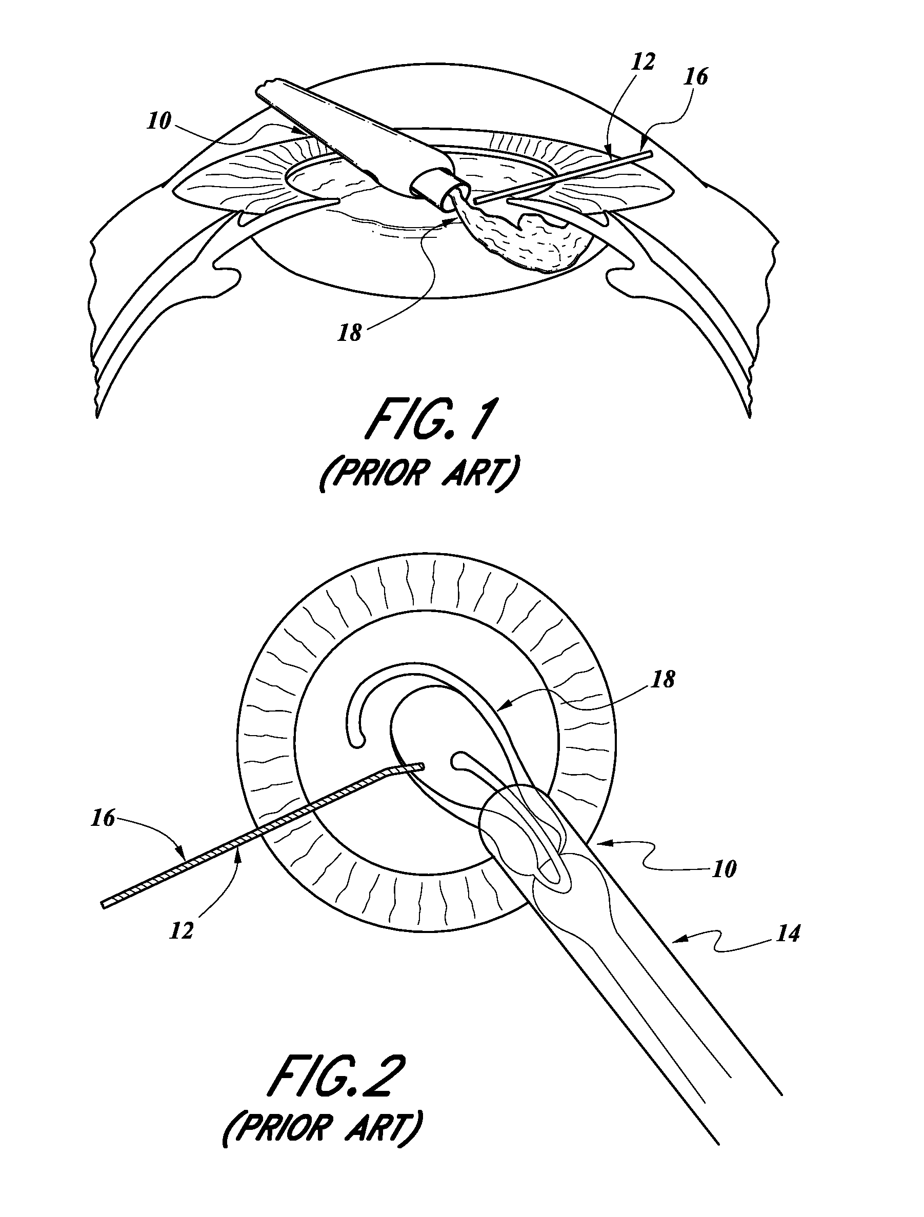
With reference to FIGS. 1 and 2, such a prior art type of cataract surgery includes using a surgical microscope to view the interior of the eye through a patient's cornea and iris. The surgeon typically makes two incisions 10, 12 in the patient's cornea, close to the limbus, to enable surgical instruments to gain access to the interior segment of the eye and to implant an intraocular lens after the cataract crystalline lens has been removed. For example, an intraocular lens inserter 14 can be inserted through the incision 10 and a positioning device 16 can be inserted through the incision 12.
The surgery typically includes creating a full-circle tear in the center of the capsular bag on the interior side, called a "capsulorhexis," and remove the torn circle of the capsule. Then, the cataract crystalline lens is removed using a phacoemulsifer, an ultrasonic infusing and aspirating instrument that breaks up the cataract and aspirates the fragments, removing the cataract.
The lingering cortical material that is attached to the inner surface of the capsular bag is then aspirated using an infusion/aspirating instrument. The intraocular lens 18 is then inserted using the lens inserter 14 and positioned within the capsular bag using the positioning device 16 or other devices.
The lens inserter 14 transfers the flat intraocular lens 18 through the small clear corneal incision 10 into the capsular opening (capsulorhexis) and to its final position within the capsular bag. The inserter 14 pushes the flat lens 18 through a cartridge which causes the lens to fold and pass through a tubular portion of the cartridge which is placed into the small incision 10. As the lens 18 emerges out of the tubular end of the cartridge 14, it slowly unfolds and returns to its original flat shape.
Recent advances in femtosecond laser instrumentation has automated the process of making entry incisions and the capsulorhexis as well as pre-cutting the cataract making the cataract surgical procedure more precise, safer, and easier for the surgeon to execute.
The majority of current lens inserters are manually operated re-usable instruments with primarily one of two means to push the lens: a lead screw or plunger. The lead screw approach provides consistent and smooth delivery of the lens, however slowly, and requires the surgeon or an assistant to turn the manual lead screw as the surgeon positions the tip of the instrument
The plunger approach does not require an assistant, as the surgeon uses their thumb to drive the lens forward, much like injecting a drug from a syringe. Additionally, the surgeon can more readily control the speed of delivery, swiftly moving though the less critical portions and slowing for the more delicate segments. A draw back of the plunger approach can emerge when the lens becomes stuck resulting in a more forceful push by the surgeon where upon clearance of the hang-up, the lens can over-shoot its exit and injure the patient.
Re-usable instrumentation requires re-processing (cleaning and sterilization) resulting in additional instrumentation overhead and increased risk of Toxic Anterior Segment Syndrome (TASS) http://www.cdc.gov/mmwr/preview/mmwrhtml/mm5625a2.htm.
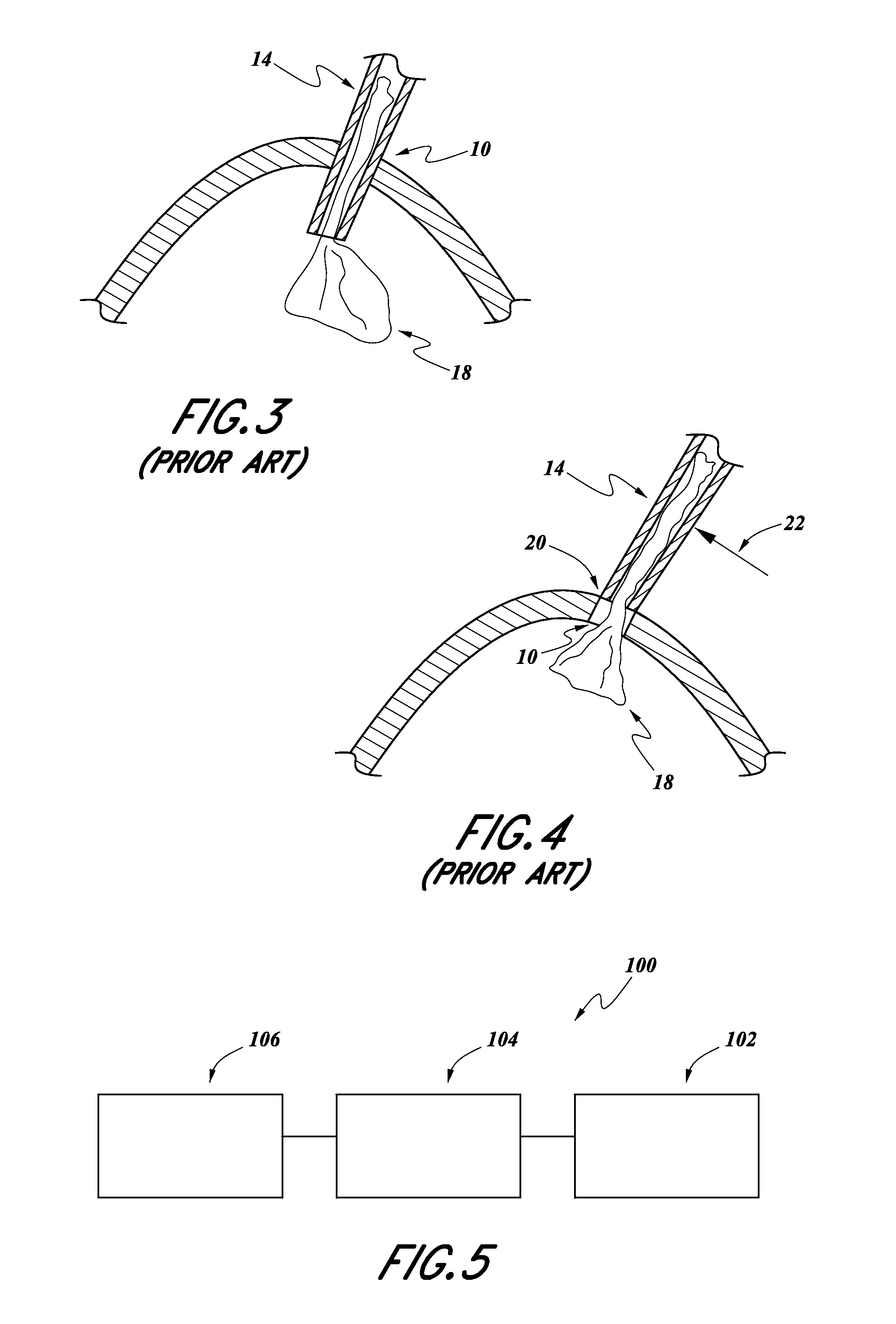
Recently, efforts have been made to perform such lens replacement surgeries using smaller corneal incisions. For example, as shown schematically in the illustration of FIG. 3, typically, the distal end of an intraocular lens inserter 14 is inserted completely through the incision 10, during a procedure of inserting an intraocular lens 18.
However, with reference to FIG. 4, recently surgeons have been adopting a "wound-assist" technique, wherein only a small portion of the tip 20 of the intraocular lens inserter 14 is inserted into the incision 10, wherein the incision 10 is smaller than the incisions previously made, such as during the procedure illustrated in FIG. 3. As such, the intraocular lens 18, in its folded state, is pushed through and slides along interior surfaces of the incision 10. This allows the incision 10 to be smaller and the wound itself (incision 10) becomes a lumen for inserting the lens 18 into the eye.
During such a procedure, the surgeon can use the distal end 20 of the tip of the intraocular inserter 14 to help hold the incision 10 open. For example, the surgeon might apply a lateral force in the direction of arrow 22 in order to hold the incision 10 open such that the lens 18 can be pushed therethrough.
SUMMARY OF THE INVENTION
An aspect of at least one of the inventions disclosed herein includes the realization that an intraocular lens inserter design can allow a surgeon to actuate and thus discharge a lens from an inserter device with one hand can provide a surgeon and can also reduce the manual force that must be applied by the surgeon. For example, in some known conventional devices, such as plunger devices, a surgeon must use significant manual force against the proximal end of the plunger to push the lens through the end of the inserter device. This makes it more difficult for the surgeon to hold the device in the desired orientation and location during insertion. This problem is more significant in the surgical procedures more recently adopted such as that described above with reference to FIG. 4. Thus, an intraocular lens insertion device that provides assisted discharge force can help a surgeon perform the surgical procedure as desired.
Another aspect of at least one of the inventions disclosed herein includes the realization that significant costs for such devices can be reduced by the use of an inserted device having an incorporated mechanism for storing energy for providing a discharge force, which is not connected by a tether, for example, to a separate console. For example, some known types of surgical devices include electrical motors or pneumatic systems that are operated by standalone consoles that provide either electrical power to an electric motor or compressed air to a compressed air motor inside a handpiece of a surgical device. Such systems require the surgeons to purchase or rent the console devices for use with such specialized surgical tools.
Thus, by providing an intraocular lens inserter with energy storage for providing a discharge force, the intraocular lens inserter is more portable and avoids the requirement for a surgeon to purchase or rent a separate standalone console.
Another aspect of at least one of the inventions disclosed herein includes the realization that compressible energy storage devices, such as springs, or compressed air, can provide convenient and portable means for storage of energy which can be output as forces. However, such energy storage devices are more difficult to control for providing, for example, constant velocity output. Thus, an aspect of at least one of the inventions disclosed herein includes the realization that providing an actuating circuit operating with a substantially incompressible fluid, such as a liquid, accommodates the use of mechanisms that can provide more fine control over the velocity of downstream components, even where energy is supplied by a compressible storage device, such as springs or compressed air.
Another aspect of at least one of the inventions disclosed herein includes the realization that a hand-held intraocular lens inserter can be made with an incorporated energy storage device and a movement control actuator, with sufficient simplicity that the resulting device can be designed as a single use device and thus disposable, thereby avoiding the costs of resterilization and the potential for cross-contamination. Thus, for example, an intraocular lens inserter device can include a compressible energy storage device and an actuator configured to operate with a substantially incompressible fluid for controlling the release of the energy stored by the energy storage device and the movement of downstream components, such as a lens insertion rod.
This summary is provided to introduce a selection of concepts in a simplified form that are further described below in the Detailed Description. This summary is not intended to identify key features or essential features of the claimed subject matter, nor is it intended to be used as an aid in determining the scope of the claimed subject matter.
BRIEF DESCRIPTION OF THE DRAWINGS
A more complete understanding of the subject matter may be derived by referring to the Detailed Description and claims when considered in conjunction with the following figures, wherein like reference numerals refer to similar elements throughout the figures.
FIG. 1 is an enlarged sectional view of a human eye with an intraocular lens inserter inserted through an incision in the cornea and a positioning device inserted through a second incision, with an intraocular replacement lens shown as being partially ejected from the intraocular lens inserter.
FIG. 2 is a front plan view of the procedure illustrated in FIG. 1.
FIG. 3 is a schematic diagram of a portion of the arrangement shown in FIG. 1, with the distal tip of an intraocular lens inserter inserted completely through an incision and discharging a replacement lens.
FIG. 4 is a schematic illustration of a different procedure than that illustrated in FIG. 3, in which the distal tip of the intraocular lens inserter is inserted only partially into the incision.
FIG. 5 is a schematic illustration of an embodiment of an intraocular lens inserter.
FIG. 6 is a perspective view of a further embodiment of an intraocular lens inserter.
FIG. 7 is a side elevational and cross-sectional view of the intraocular lens inserter of FIG. 6.
FIG. 8 is a side elevational and cross-sectional view of a portion of a housing member of the intraocular lens inserter of FIG. 7.
FIG. 9 is an enlarged sectional view of an energy storage portion of the lens inserter of FIG. 6 and in a partially exploded view;
FIG. 10 is also a cross-sectional view of lens inserter of FIG. 6 showing an energy storage device being pierced by a piercing device and within end caps screwed down over the energy storage device.
FIG. 11 is a cross-sectional view of the inserter of FIG. 6 showing movement of a piston after an expanding gas has been discharged from the energy storage device.
FIG. 12 is an enlarged sectional view of an actuator portion of the inserter of FIG. 6.
FIG. 13 is an exploded view of a lens cartridge holder portion of the inserter of FIG. 6.
FIG. 14 is an enlarged perspective and exploded view of the inserter shown in FIG. 13.
FIG. 15 is an enlarged side elevational view of a lens cartridge removed from the lens cartridge holding portion.
FIG. 16 is a view of the inserter of FIG. 15 with the lens cartridge inserted into the lens cartridge holder portion.
FIG. 17 is a partial cross-sectional view of the inserter of FIG. 16 prior to the lens cartridge being engaged with a plunger.
FIG. 18 is a cross-sectional view of the inserter shown after the lens holder portion has been moved axially to engage the plunger with the lens cartridge.
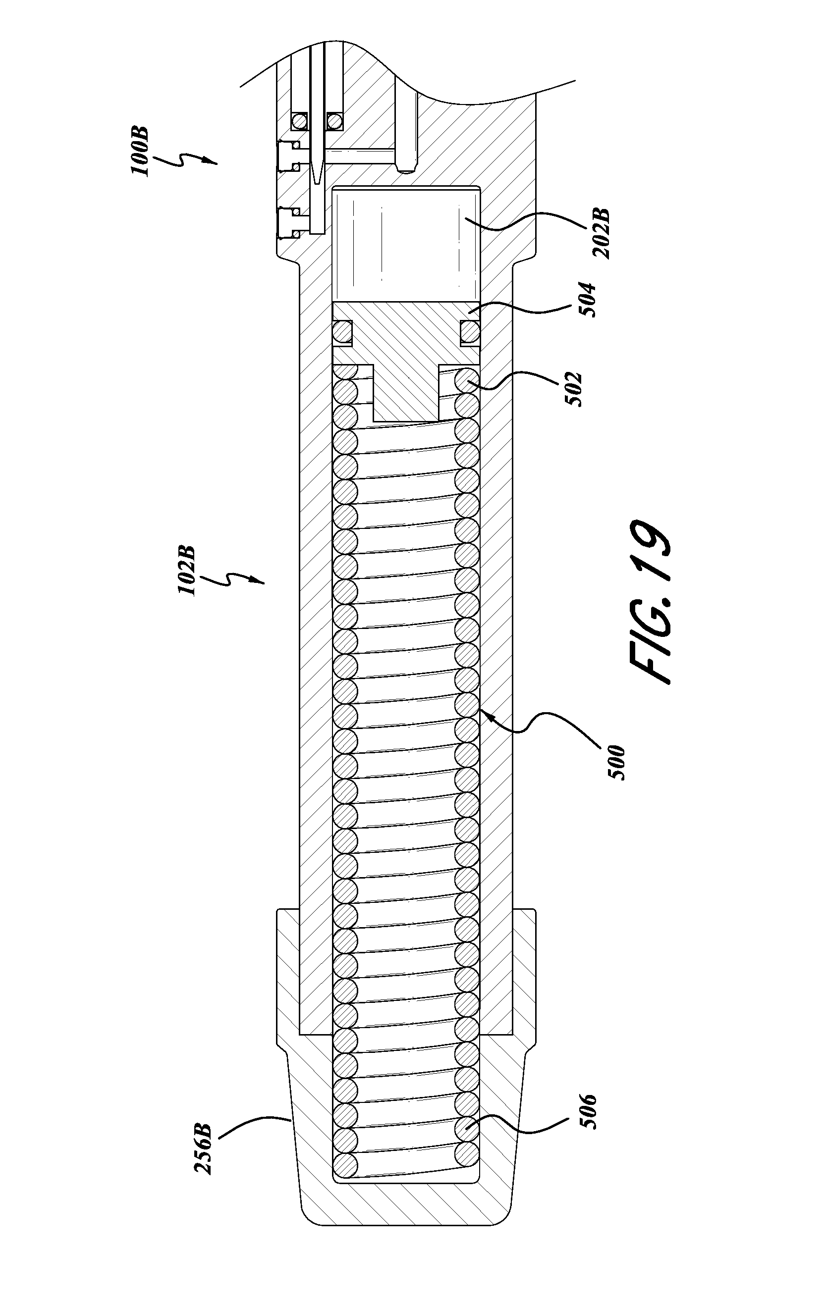
FIG. 19 is an illustration of a further embodiment of the inserter in FIG. 6, in which the energy storage device is in the form of a spring.
DETAILED DESCRIPTION OF THE PREFERRED EMBODIMENT
The following detailed description is merely illustrative in nature and is not intended to limit the embodiments of the subject matter or the application and uses of such embodiments. As used herein, the word "exemplary" means "serving as an example, instance, or illustration." Any implementation described herein as exemplary is not necessarily to be construed as preferred or advantageous over other implementations. Furthermore, there is no intention to be bound by any expressed or implied theory presented in the proceeding technical field, background, brief summary, or the following detailed description.
Certain terminology may be used in the following description for the purpose of reference only, and thus are not intended to be limiting. For example, terms such as "upper", "lower", "above", and "below" refer to directions in the drawings to which reference is made. Terms such as "proximal", "distal", "front", "back", "rear", and "side" describe the orientation and/or location of portions of the component within a consistent but arbitrary frame of reference which is made clear by reference to the text and the associated drawings describing the component under discussion. Such terminology may include the words specifically mentioned above, derivatives thereof, and words of similar import. Similarly, the terms "first", "second", and other such numerical terms referring to structures do not imply a sequence or order unless clearly indicated by the context.
The inventions disclosed herein are described in the context of intraocular lens inserters for the treatment of cataracts. However, the inventions disclosed herein can be used in other context as well with regard to surgical devices that are required to discharge devices, for example, into or beyond the tissues of an animal, such as a human.
With reference to FIG. 5, an intraocular lens inserter 100 can include an energy storage device 102, an actuator device 104, and a lens discharge portion 106. The energy storage portion 102 can be in the form of any type of energy storage device. In some embodiments, the energy storage portion 102 is in the form of a device for storing a compressible fluid, mechanical springs, or other compressible types of energy storage devices. Other types of energy storage devices can also be used.
In some embodiments, the energy storage portion 102 can be configured to discharge mechanical energy from the energy stored therein. For example, where the energy storage device 102 is in the form of a compressed gas container, the energy storage device 102 can discharge such compressed gas which therefore provides an output of mechanical energy. Similarly, where the storage device 102 is in the form of a mechanical spring, such a spring can output linear or torsional movement, which is also a form of mechanical energy.
The actuator portion 104 can be any type of actuator configured to provide controllable actuation of the output of mechanical energy from the energy storage portion 102. For example, in some embodiments, the actuator portion 104 can be in the form of a mechanical or electronic button or lever for providing a user with means for controlling the output of mechanical energy from the energy storage portion 102. For example, the actuator 104 can be in the form of a button or other electronic devices configured to provide variable resistance or movement associated with a mechanical member used for outputting the energy from the energy storage portion 102. The actuator portion 104 can also provide for the control of an output member configured for interaction with the intraocular lens portion 106. For example, the actuator portion 104 can include an output plunger or other device for interacting with the intraocular lens portion.
The intraocular lens portion 106 can be configured to interact with or retain an intraocular lens cartridge which is widely commercially available from several different sources. For example, the intraocular lens portion 106 can be configured to releasably engage with an intraocular lens cartridge commercially available as a Monarch available from Alcon. The intraocular lens portion 106 can also be configured to move between an open position configured for allowing an intraocular lens cartridge to be engaged with the lens portion 106 and a closed portion in which the lens portion 106 engages with the lens cartridge.
As such, in operation, the actuator portion 104 can be manipulated by a user, such as a surgeon, to control the output of mechanical energy from the energy storage portion 102, to thereby control the discharge of a lens from a lens cartridge retained by the lens portion 106. Further, the inserter 100 can be configured to be hand-held, and in some embodiments, disposable.
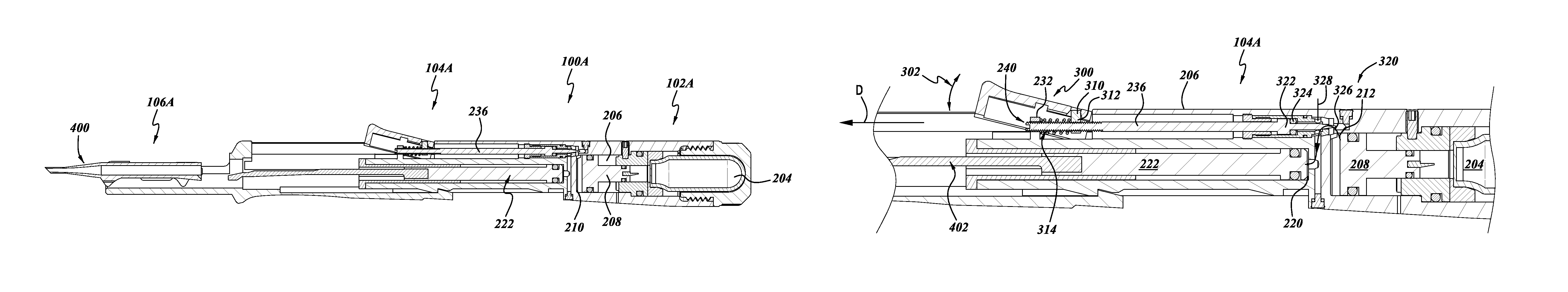
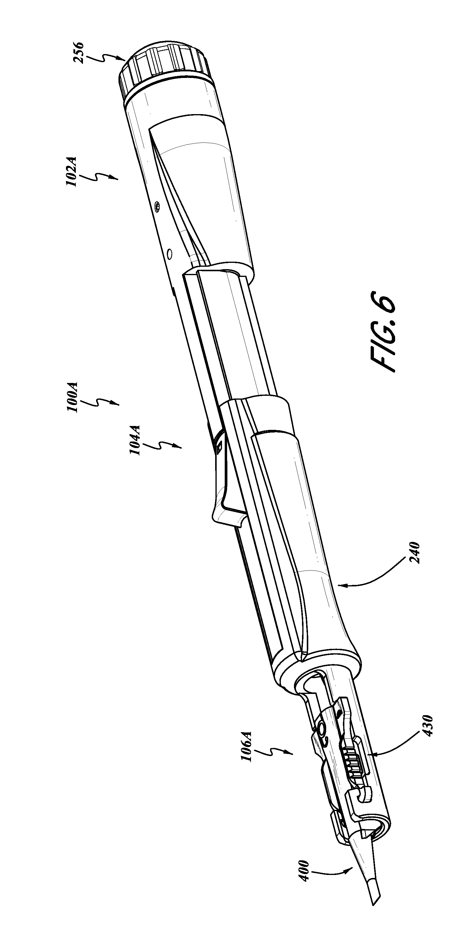
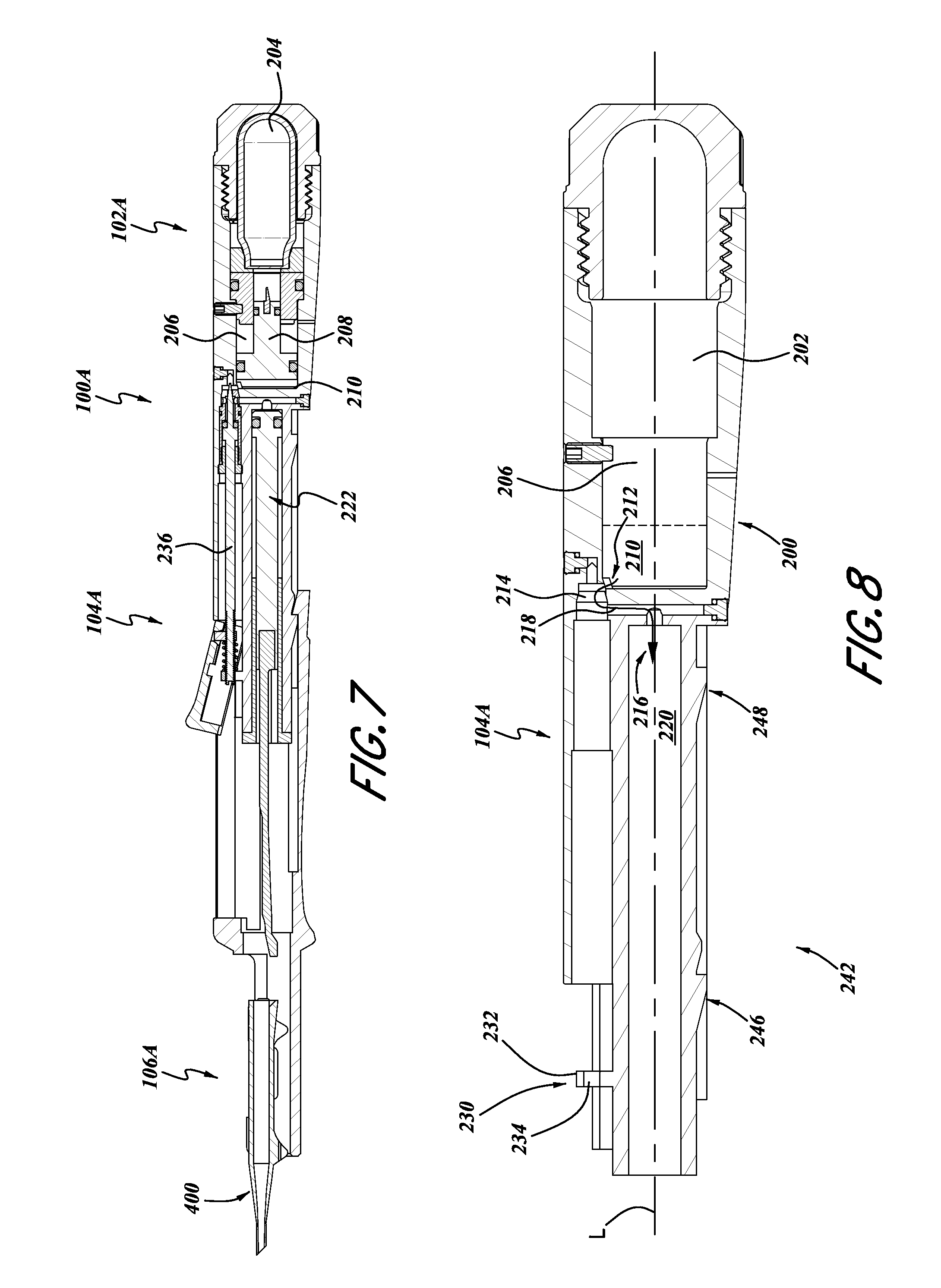
With reference to FIGS. 6-18, a further embodiment of the lens inserter 100 is illustrated there and identified by the reference number 100A. The features and components of the lens inserter 100A that can be the same or similar to corresponding components of the lens inserter 100 have been identified with the same reference numeral, except that the letter "A" has been added thereto.
With reference to FIGS. 6-8, the intraocular lens inserter 100A also includes an energy storage portion 102A, an actuator portion 104A, and a lens portion 106A.
In the illustrated embodiment, with reference to FIG. 8, the inserter 100A includes a main body portion 200 which includes various cavities, recesses, and conduits, and, in the present embodiment, provides for communication between the energy storage portion 102A and the actuator portion 104A. FIG. 8 illustrates the body portion 200 with all other components removed therefrom. In some embodiments, optionally, the body portion 200 can be made from a single piece of material forming a monolithic body. However, other configurations can also be used.
In some embodiments, the body portion 200 includes an energy storage receiving portion 202. In some embodiments, the receiving portion 202 is configured as a recess within the body 200, sized and configured to receive a container of compressed gas. In some embodiments, the recess 202 can be sized to receive a canister of compressed carbon dioxide 204. Such containers of compressed gas and, in particular, carbon dioxide, are widely commercially available.
The housing 200 can also include a piston chamber 206 configured to receive gas discharged from the container 204. The piston chamber 206 can include devices for interacting with the gas from the container 204 for providing usable mechanical energy. For example, as shown in FIG. 7, a piston 208 can be disposed in the piston chamber portion 206. In some embodiments, the piston 208 subdivides the piston chamber portion 206 into a gas-receiving portion and a liquid-receiving portion 210.
The housing 200 can also include a conduit 212 connecting the energy storage portion 102A with the actuator portion 104A. For example, the conduit 212 can provide a flow path between the liquid receiving portion 210, along the direction of arrow 216, into the actuator portion 104A.
The conduit 212 can include an aperture in a portion of the liquid-receiving portion 210, that leads into an actuator control portion 214, then to a lateral connector portion 218, into a further liquid-receiving portion 220 of the actuator portion 104A.
The actuator receiving portion 214 can be configured to receive an actuator for controlling the flow of fluid along the conduit 212. Additionally, the chamber 220 can be configured to receive a piston 222, described in greater detail below.
With continued reference to FIG. 8, the body 200 can also include an actuator mounting portion 230. The actuator mounting portion 230 can be in the form of a projection 232 extending radially outwardly from the longitudinal axis L of the body 200. The projection 232 can include an aperture 234 and could be configured to receive an actuator rod 236 (FIG. 7).
The body 200 can also include various other outer surfaces and devices for engagement with a sliding cartridge engagement member 240 (FIG. 6), described in greater detail below. For example, the outer surface 242 of the actuator portion 104A of the body 200 can include various engagement devices 246, 248, and/or other ridges for providing alignment and engagement with the engagement device 240. Such features are described in greater detail below with reference to FIG. 14.
With reference to FIGS. 9-11, the storage portion 102A is illustrated in further detail, including various components that can be included within the body member 200. The distal end 250 of the body member 200 can include internal threads 252 configured for engagement with external threads 254 disposed on a removable end cap 256.
Additionally, the energy storage portion 102A can include a bulkhead member 260. The bulkhead member 260 can be configured to provide for secure engagement with a chosen energy storage device used with the energy storage portion 102a. As noted above, the illustrated embodiment is designed for use with a cartridge of compressed carbon dioxide 204. Thus, in the illustrated embodiment, the bulkhead member 260 includes an upstream end 262 configured for abutting engagement with a distal end 205 of the cartridge 204. The bulkhead member 260 can also include a sealing device, such as an O-ring 264, for providing a sealing engagement with an inner surface of the piston chamber 206. In the illustrated embodiment, the bulkhead member 260 remains stationary during operation. Thus, the inserter 100a also includes a set screw 266 which extends through the body portion 200 for secure engagement with the bulkhead member 260. Other designs can also be used.
The energy storage portion 102A can also include an accumulator piston 280. In the illustrated embodiment, the accumulator piston 280 is slidably engaged with two surfaces. Firstly, the accumulator piston 280 includes a first portion 282 engaged with an inner surface of the bulkhead member 260 and a downstream portion 284 engaged with an inner surface of the piston chamber 206. Additionally, in the illustrated embodiment, the piston 280 includes a piercing needle 286 which is configured to pierce a seal that is commonly used on compressed gas cartridges, such as the carbon dioxide compressed gas cartridge 204.
The piston 280 is configured to move slidably along the longitudinal axis L of the inserter 100A. As such, the piston 280 includes an O-ring 288 for sealing against the inner surface of the bulkhead 260 and a second O-ring 290 for providing a sliding seal with the inner surface of the piston chamber 206.
In some embodiments, the O-ring seal 288 can be configured to maintain all of the gas discharged from the cartridge 204 in the area 292 disposed between the piston 280 and the cartridge 204. Additionally, the piston chamber 206 can be configured to receive a substantially incompressible fluid, such as a liquid, including but not limited to, silicone oil, propylene glycol, glycerin, saline, water, or other substantially incompressible fluids. For purposes of illustration, the piston 280 and the downstream or distal portion of the piston chamber 206 can be considered as a substantially incompressible fluid-receiving chamber 300. Thus, in some embodiments, the O-ring 290 is configured to maintain any liquid or fluid in the chamber 300 in the distal portion of the chamber 206.
During operation, when the cap 256 is screwed into the threads 252, the cartridge 204 is thereby pushed into the piercing needle 286, thereby opening the cartridge 204 and releasing the compressed gas therein into the space between the cartridge 204 and the bulkhead 260 and the distal proximal end portion 282 of the piston 280.
With reference to FIG. 11, when the actuator portion 104A is operated appropriately, the pressurized gas from the cartridge 204 continues to expand into the gas-receiving portion 292, thereby pressurizing any fluid or liquid in the substantially incompressible fluid receiving portion 301. Actuation of the actuator portion 104A allows the pressurized fluid in the chamber 301 to flow outwardly therefrom and into the chamber 220 to thereby drive the piston 222 longitudinally in the direction of arrow R (FIG. 11), described in greater detail below.
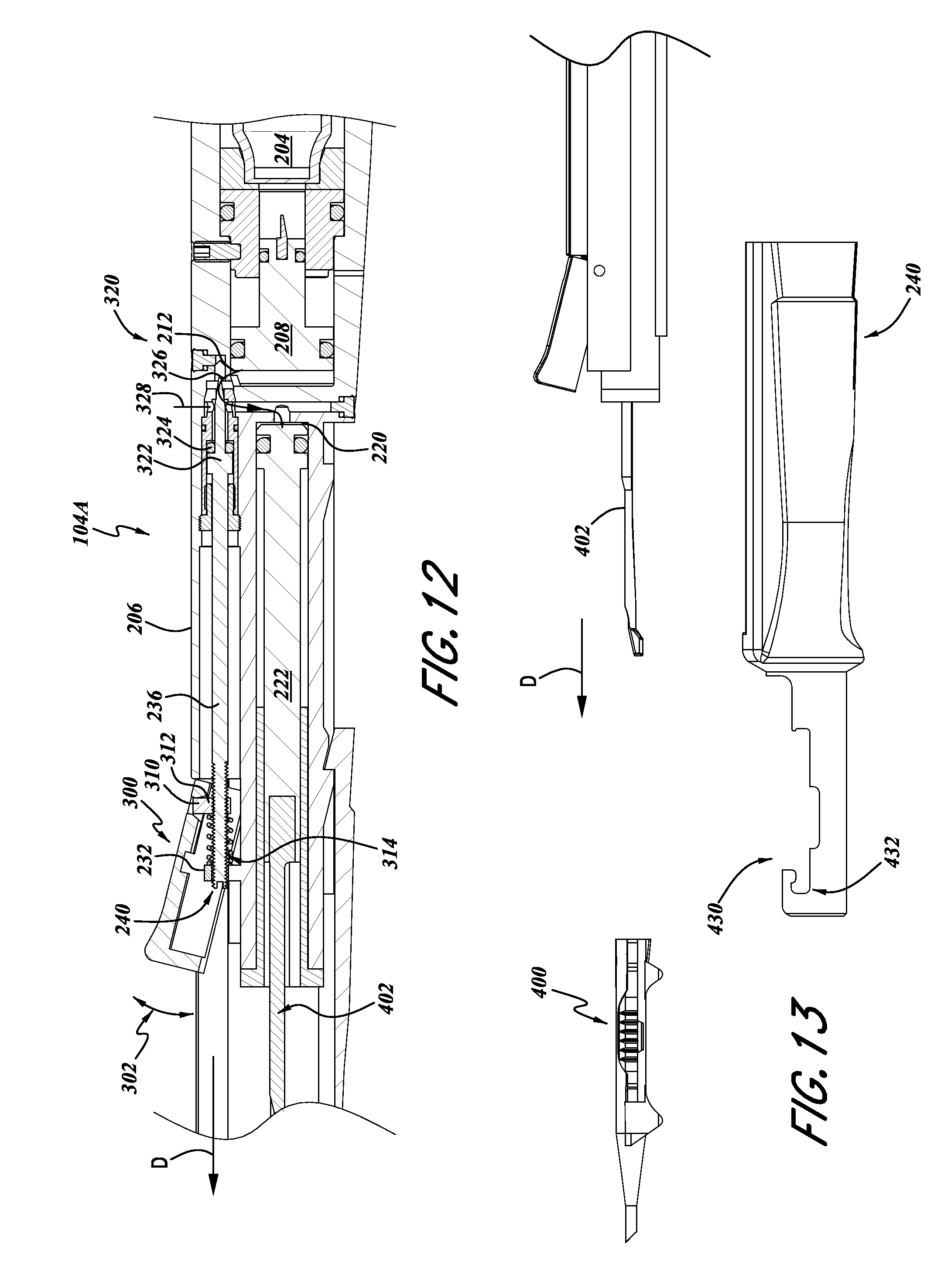
With continued reference to FIG. 12, the actuator portion 104A can include an actuator member 300 mounted relative to the housing member 200 so as to be movable between an unactuated position (illustrated in FIG. 12) and an actuated position (not shown). For example, the lever member 300 can be attached to the housing 200 with the hinge member (not shown), such that the actuator member can be pivotable along the arc 302. The actuator member 300 can also be engaged with the rod 236 which can be configured to provide a flow control function for controlling the flow of substantially noncompressible fluid from the chamber 300 toward the chamber 220 for moving the piston 222. For example, the piston rod 236 can include a distal end 240 which extends through the aperture 234 of the projection 232 and a proximal end 320 configured to provide a flow control function.
The distal end 240 of the rod 236 can include a slot for engagement with a screwdriver to provide adjustment of the positioning of the rod 236. For example, the lever member 300 can also include an engagement member 310 pivotally mounted to the lever member 300. The engagement member 310 can include a threaded portion 312 configured for engagement with external threads on the distal portion 240 of the rod 236.
Additionally, a spring 314 can provide a bias of the lever member 300 to the unactuated position. Connected as such, when the lever mover 300 is moved through the arc 302, and more particularly, when the lever member 300 is moved downwardly from the position illustrated in FIG. 12, the engagement member pulls the rod 236 in a distal direction D, thereby moving the flow control portion 320 in the direction of arrow D. The spring 314 provides a bias return action for returning the lever member 300 to the position illustrated in FIG. 12, when released by a user.
With continued reference to FIG. 12, the proximal portion 320 of the rod 236 can include a piston member 322 and seal, in the form of an O-ring 324. The proximal portion 320 can also include a needle portion 326 configured to cooperate with a throat portion 328. Using well known techniques, the engagement and cooperation of the needle portion 326 with the throat portion 328 can be used to control a flow of substantially incompressible fluid along the conduit 212. For example, when the lever 300 is moved downwardly from the position illustrated in FIG. 12, the piston rod is moved distally in the direction D, thereby moving the needle portion 326 also in the direction of arrow D, thereby forming or increasing a gap between the needle portion 326 and the throat portion 328. As such, fluid flows through the conduit 212, for example, a substantially incompressible fluid pressurized by the piston 208 due to interaction with gas discharged from the cartridge 204 can thereby flow through the conduit 212 toward the piston 222.
When the substantially incompressible fluid presses against the piston 222, the piston 222 also moves in the direction of arrow D. This movement of the piston 222 can be used to discharge a lens from the cartridge 400. More specifically, as illustrated in FIGS. 12 and 13, a plunger 402 can be attached to a distal end of the piston 222. Thus, as the piston 222 is moved by the flow of fluid through the conduit 212, the plunger 402 is also moved in the direction of arrow D. This movement of the plunger 402 can be used to discharge a lens disposed within the cartridge 400, in a technique that is well known in the art.
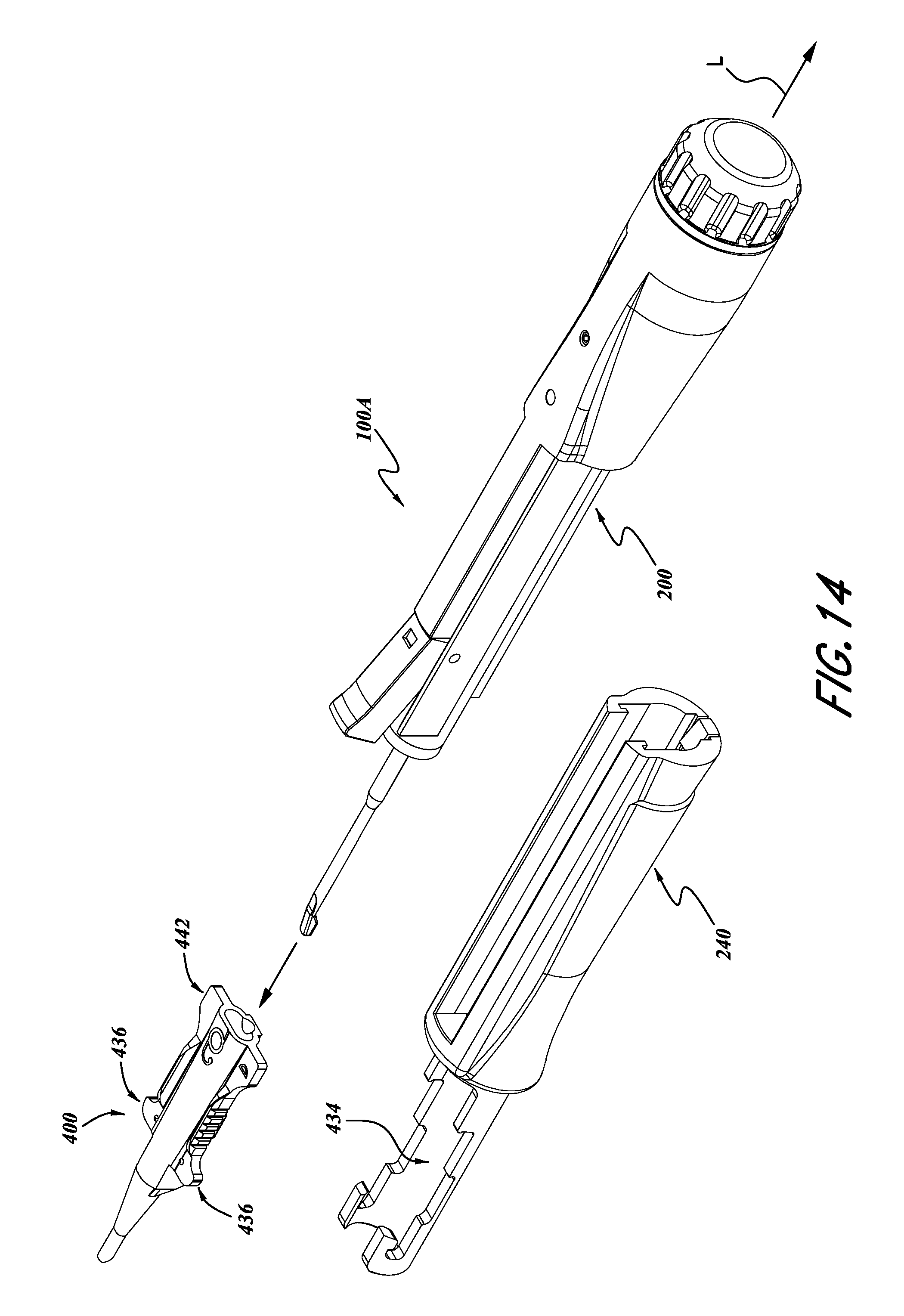
With reference to FIGS. 13 and 14, the cartridge engagement member 240 can include a cartridge receiving portion 430. For example, the cartridge receiving portion 430 can include a distal wing engagement portion 432 and a body receiving portion 434. The wing receiving portion 432 and the body receiving portion 434 can be sized in accordance with the outer dimensions of commercially available lens cartridges 400, which are well known in the art.
The distal wing receiving portion 432 can include a recess designed to engage the wings 436 of the lens cartridge 400. Thus, when the cartridge 400 is engaged with the cartridge receiving portion 430, as shown in FIG. 6, the cartridge 400 is generally aligned with the plunger 402.
With continued reference to FIGS. 15 and 16, the cartridge receiving portion 430 can optionally include a proximal engaging portion 440 configured to engage with a proximal portion of the cartridge 400. For example, in some commercial embodiments of the cartridge 400, the cartridge 400 includes rearward wings 442 or other rearward surfaces. The cartridge engagement portion 430, therefore, can include an additional proximal recess 444 and an engagement device 446, for a positive engagement with the wings 442. Thus, as shown in FIG. 16, when the cartridge 400 is engaged both with the forward engagement portion 432 and the rearward engagement portion 444, with the projection 446 extending over the rearward wings 442, the cartridge 400 is more securely seated within the cartridge receiving portion 430.
This can provide a substantial benefit to a surgeon using the inserter 100a. For example, with the projection 446 extending over the rearward wing 442, if the surgeon applies a force to the inserter 100a, in the direction of arrow F (FIG. 16), a torque T can be created or imparted onto the cartridge 400, thereby tending to cause the cartridge to pivot about the distal receiving portion 432, which can thereby tend to cause the proximal end of the cartridge 400 to lift upwardly in the direction of arrow U. However, the engagement portion 446 can help retain the proximal portion of the cartridge 400 within the receiving portion 430. This type of force can be created during execution of surgical procedures that are becoming more common, such as that described above with reference to FIG. 4, known as the "wound-assist" technique.
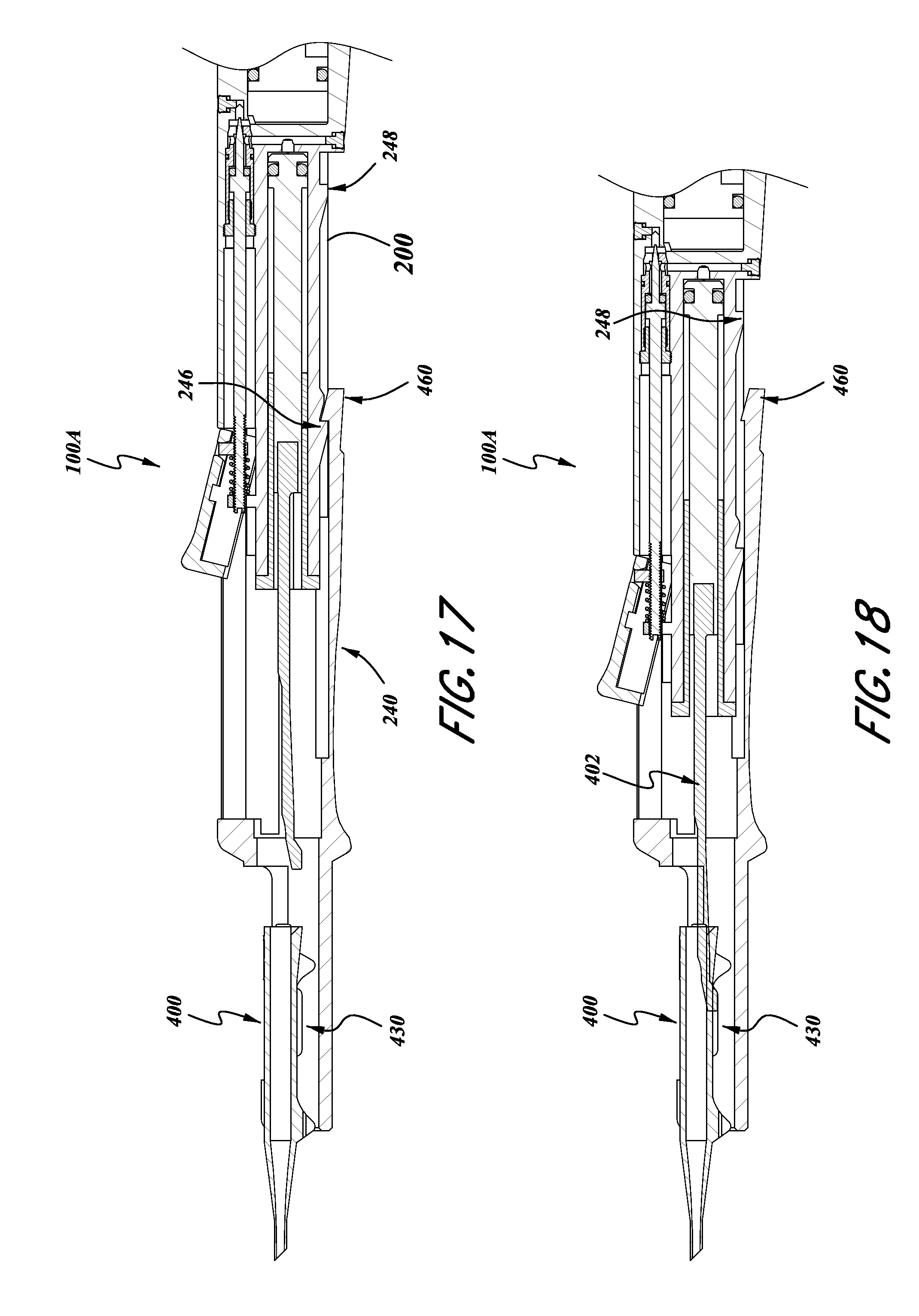
With continued reference to FIGS. 14-18, the member 240 can also be slidably engaged with the body 200. Thus, the member 240 can include various internal surfaces configured to cooperate with outer surfaces of the body 200. Thus, the member 240 can be slid longitudinally along the body 200, parallel to the longitudinal axis L of the inserter 100a.
For example, with reference to FIGS. 17 and 18, the portion 240 can be moved to a distal position, show in FIG. 17. In this position, the lens receiving portion 430 is spaced apart from the plunger 402. As such, the cartridge 400 can be inserted into the cartridge receiving portion 430 without interference of the plunger 402. Thus, after the cartridge is received as such, as shown in FIG. 18, the portion 240 can be slid backwards relative to the body 200 until the plunger 402 engages or presses against a lens within the cartridge 400.
As noted above, the body 200 can include various detents or ramps or other portions 246, 248 which can engage with a portion of the member 240 for providing positive engagement into various positions. For example, the portion 240 can include a ramp and hook portion 460 configured to engage with the portion 246 and portion 248 of the housing member 200. Thus, the member 240 can be positively engaged in the position illustrated in FIG. 17 with the body member 200, and then when pulled in the proximal direction, so as to move the plunger 402 into the cartridge 400, the portion 460 can engage with the proximal portion of the housing 200 to thereby engage into a retracted position. Other designs can also be used to provide for the convenient insertion and removal of the cartridge 400.
With reference to FIG. 19, a further embodiment of the inserter 100a is illustrated therein and identified generally by the reference numeral 100b. The components of the inserter 100b that can be the same or similar to the inserter 100a are identified with the same reference numerals, except that a letter "b" has been added thereto.
With continued reference to FIG. 19, the energy storage portion 102b can be configured to use a compressive energy storage function of a coiled spring 500. The coiled spring can include a distal end 502 engaged with a piston 504 and a proximal end 506 held in place with a removable cap 256b. The piston 504 can be configured to form a seal, for example, with an O-ring 506, so as to operatively contain a substantially incompressible fluid in the chamber 202b. The remaining portions of the inserter 100b can be constructed in accordance with the description of the inserter 100a above.
While at least one exemplary embodiment has been presented in the foregoing detailed description, it should be appreciated that a vast number of variations exist. It should also be appreciated that the exemplary embodiment or embodiments described herein are not intended to limit the scope, applicability, or configuration of the claimed subject matter in any way. Rather, the foregoing detailed description will provide those skilled in the art with a convenient road map for implementing the described embodiment or embodiments. It should be understood that various changes can be made in the function and arrangement of elements without departing from the scope defined by the claims, which includes known equivalents and foreseeable equivalents at the time of filing this patent application.
* * * * *
References
D00000
D00001
D00002
D00003
D00004
D00005
D00006
D00007
D00008
D00009
D00010
XML
uspto.report is an independent third-party trademark research tool that is not affiliated, endorsed, or sponsored by the United States Patent and Trademark Office (USPTO) or any other governmental organization. The information provided by uspto.report is based on publicly available data at the time of writing and is intended for informational purposes only.
While we strive to provide accurate and up-to-date information, we do not guarantee the accuracy, completeness, reliability, or suitability of the information displayed on this site. The use of this site is at your own risk. Any reliance you place on such information is therefore strictly at your own risk.
All official trademark data, including owner information, should be verified by visiting the official USPTO website at www.uspto.gov. This site is not intended to replace professional legal advice and should not be used as a substitute for consulting with a legal professional who is knowledgeable about trademark law.