Connecting a peripheral device
Nguyen , et al. Ja
U.S. patent number 10,185,686 [Application Number 15/306,101] was granted by the patent office on 2019-01-22 for connecting a peripheral device. This patent grant is currently assigned to Hewlett-Packard Development Company, L.P.. The grantee listed for this patent is HEWLETT-PACKARD DEVELOPMENT COMPANY, L.P.. Invention is credited to Peter W Austin, Michael Nguyen, Binh T Truong.


| United States Patent | 10,185,686 |
| Nguyen , et al. | January 22, 2019 |
| **Please see images for: ( Certificate of Correction ) ** |
Connecting a peripheral device
Abstract
The present disclosure describes a peripheral device. The peripheral device includes a device communication port to communicatively couple with a computer communication port on a computer. The peripheral device includes an automatic latch to mechanically secure the peripheral device to the computer by applying pressure in a direction that connects the device communication port and the computer communication port. The peripheral device includes a ground retention clip, to establish surface contact with an exterior surface of the computer to electrically ground the peripheral device.
| Inventors: | Nguyen; Michael (Houston, TX), Truong; Binh T (Houston, TX), Austin; Peter W (Houston, TX) | ||||||||||
|---|---|---|---|---|---|---|---|---|---|---|---|
| Applicant: |
|
||||||||||
| Assignee: | Hewlett-Packard Development
Company, L.P. (Houston, TX) |
||||||||||
| Family ID: | 55217947 | ||||||||||
| Appl. No.: | 15/306,101 | ||||||||||
| Filed: | July 28, 2014 | ||||||||||
| PCT Filed: | July 28, 2014 | ||||||||||
| PCT No.: | PCT/US2014/048452 | ||||||||||
| 371(c)(1),(2),(4) Date: | October 23, 2016 | ||||||||||
| PCT Pub. No.: | WO2016/018222 | ||||||||||
| PCT Pub. Date: | February 04, 2016 |
Prior Publication Data
| Document Identifier | Publication Date | |
|---|---|---|
| US 20170168973 A1 | Jun 15, 2017 | |
| Current U.S. Class: | 1/1 |
| Current CPC Class: | G06F 1/1607 (20130101); G06F 13/385 (20130101); G06F 13/4282 (20130101); G06F 1/16 (20130101); G06F 1/1684 (20130101); G06F 13/409 (20130101); H01R 24/64 (20130101); H01R 2107/00 (20130101) |
| Current International Class: | G06F 1/16 (20060101); G06F 13/38 (20060101); G06F 13/40 (20060101); G06F 13/42 (20060101); H01R 24/64 (20110101) |
References Cited [Referenced By]
U.S. Patent Documents
| 5825617 | October 1998 | Kochis |
| 6282088 | August 2001 | Canova |
| 7318551 | January 2008 | Mills |
| 7433185 | October 2008 | Curran |
| 7554800 | June 2009 | Bragg |
| 8029322 | October 2011 | Oh et al. |
| 8369061 | February 2013 | Chu |
| 8496213 | July 2013 | Kunert |
| 8775710 | July 2014 | Miller |
| 8972617 | March 2015 | Hirschman |
| 9678537 | June 2017 | Kupferstein |
| 2002/0054476 | May 2002 | Han |
| 2004/0073819 | April 2004 | Sekine et al. |
| 2004/0093363 | May 2004 | Cargin, Jr. |
| 2007/0019371 | January 2007 | Yang |
| 2010/0066677 | March 2010 | Garrett et al. |
| 2012/0057306 | March 2012 | Liu |
| 2012/0266235 | October 2012 | Majdic |
| 2013/0109316 | May 2013 | Lee |
| 2013/0167226 | June 2013 | Lin |
| 2013/0196527 | August 2013 | Joe |
| 2013/0311314 | November 2013 | Fernando et al. |
| 2014/0327998 | November 2014 | Barneron |
| 2016/0249476 | August 2016 | Rohmer |
| 2017/0344065 | November 2017 | Kupferstein |
| 10166154 | Mar 2010 | CN | |||
| 1082787 | Jul 2007 | EP | |||
Other References
|
Eclipse.TM. PF315V+ All-in-One POS System, GenPOS, 2012, 1 page, Available at: <genpos.ca/en/PF315V>. cited by applicant . ER689AA--HP rp5000 Point of Sale System P4 2.4 GHz 256M/40G LAN WXP WEPOS, pp. 1-17, Hewlett-Packard Company, Available at: <10057.www1ho.com/ecomcat/hpcatalog/provisioner/05/ER689AA.htm>. cited by applicant . How Do I Change the Swappable Interface on My Star Printer?--Barcoding News, BarcodesInc, Dec. 13, 2012, 1 page, Available at: <barcodesinc.com/news/?p=7157#more-7157>. cited by applicant. |
Primary Examiner: Edwards; Anthony Q
Attorney, Agent or Firm: International IP Law Group
Claims
What is claimed is:
1. A peripheral device, comprising: a device communication port to communicatively couple with a computer communication port on a computer; an automatic latch to mechanically secure the peripheral device to the computer by applying pressure in a direction that connects the device communication port and the computer communication port, wherein the automatic latch comprises a cross-bar lever; and a ground retention clip to establish surface contact with an exterior surface of the computer to electrically ground the peripheral device.
2. The peripheral device of claim 1, wherein the automatic latch is detached by applying pressure to a cross-lever tab.
3. The peripheral device of claim 2, wherein the peripheral device comprises the cross-lever tab.
4. The peripheral device of claim 1, wherein the automatic latch comprises a spring to maintain the position of the automatic latch.
5. The peripheral device of claim 1, wherein the automatic latch mechanically secures the peripheral device to the computer such that the peripheral device stays rigid in relation to the computer.
6. A computing device, comprising: a processor; a computer communication port for connecting to a corresponding communication port of a peripheral device comprising an automatic latch to mechanically secure the peripheral device to the computing device wherein the automatic latch comprises a cross-bar lever; and a chassis comprising a latch receptacle for receiving the automatic latch to mechanically secure the peripheral device to the computing device, the chassis being in contact with a ground retention surface of the peripheral device when the peripheral device is mechanically secured.
7. The computing device of claim 6, wherein the computer communication port is a Universal Serial Bus (USB) port.
8. The computing device of claim 6, comprising a device tab used to lock and releases the cross-bar lever.
9. The computing device of claim 6, wherein the peripheral device maintains a rigid relationship to the computing device when mechanically secured.
10. A system for connecting a peripheral device to a computing device, comprising: a computing device comprising a communication port and a latch receptacle; a peripheral device, comprising: a device communication port, to communicatively couple with a computer communication port on a computer; an automatic latch comprising a cross-bar lever, to mechanically secure the peripheral device to the computer by applying pressure in a direction that connects the device communication port and the computer communication port; and a ground retention clip, to establish surface contact with an exterior surface of the computing device to electrically ground the peripheral device.
11. The system of claim 10, wherein the wherein the automatic latch is automatically detached by applying pressure to a cross-lever tab.
12. The system of claim 10, wherein the automatic latch comprises a spring to maintain the position of the automatic latch.
13. The system of claim 10, wherein the peripheral device stays rigid in relation to the computing device when mechanically secured.
Description
BACKGROUND
A peripheral device typically connects to another computing device to provide additional functionality. Peripheral devices may include a number of different devices, such as a magnetic card reader, camera, printer, biometric sensor, and many others. In a number of working environments, it is useful to have the peripheral device secured to the computing device in a stable position. For example, at a point of sale, i.e., cash register, the card reader is installed so that the force of swiping the card through the reader does not disconnect, or possibly damage, the two devices.
BRIEF DESCRIPTION OF THE DRAWINGS
Certain exemplary embodiments are described in the following detailed description and in reference to the drawings, in which:
FIGS. 1A-1B are block diagrams of an example system or connecting a peripheral device.
FIGS. 2A-2C are block diagrams of example peripheral device for connecting to a computing device.
FIG. 3 is a block diagram of an example ground retention clip, in accordance with examples.
DETAILED DESCRIPTION
Connected peripheral devices are secured to the computing device using two screws on either side of the communication port. However, attaching and removing the peripheral device can be time consuming and tedious. The screws may not be accessible from outside the device, meaning parts of the computing device are removed just to get to the screws. Further, there may be various types of screws. As such, a tool such as a screwdriver may not be useful. Instead, the tool may be provided by the peripheral device manufacturer. This means that if the tool is lost somewhere between the manufacturer, reseller, and the customer, the customer may not be able install the device until ordering, and receiving, a replacement tool. Accordingly, an alternative to connecting peripheral devices may be useful.
Examples of the claimed subject matter provide peripheral devices and computing devices that may be stably connected at a communication port, and disconnected from the port, without tools. These examples enable faster connection and disconnection times than possible between current peripheral and computing devices. Examples are described in greater detail with respect to FIG. 1.
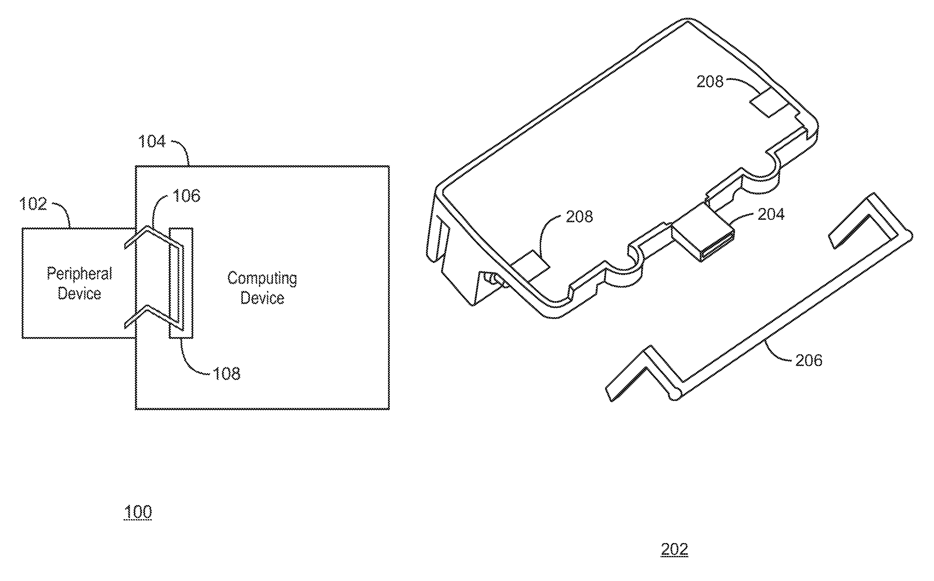
FIG. 1A is a front view of a system 100 for securing a peripheral device 102 to a computing device 104, in accordance with examples. The peripheral device 102 can be coupled to the computing device 104 to provide additional functionality. The peripheral device 102 refers to a modular device with small form factor that adds functionality to the computing device 104 by communicatively coupling to the computer via a communication port. The peripheral device 102 may be a web cam, a bar code scanner, a card reader, a finger print scanner, or a reverse-facing display screen. The computing device 104 may be a standard desktop computer, a desktop with all-in-one form factor, a tablet computer, laptop computer, point of sale device, and so on. In addition to the communicative connection, the peripheral device 102 is mechanically secured to the computing device 104 such that the peripheral device 102 stays rigid in relation to the computing device 104.
The peripheral device 102 includes a cross-bar level 106 that is disposed within a receptacle 108 of the computing device 104. In one example, the cross-bar lever 106 automatically locks upon insertion. The cross-bar lever 106 latches onto the computing device 104 to lock the devices 102, 104 into position for stability. When connected, the cross-bar lever 106 is fixed within the receptacle 108. The cross-bar lever 106 constrains any degree of motion between the peripheral device 102 and the computing device 104. Additionally, the cross-bar lever 106 may be spring loaded to a position that maintains the rigid relationship between the devices 102, 104. To disconnect the device 102, a tab lever (not shown) may be pulled, which lifts the cross-bar lever 106 from the receptacle 108. In this position, it is possible to disconnect the peripheral device 102 from the computing device 104. The tab lever may be used to secure and eject the cross-bar lever 106.
In an example of the claimed subject matter, the tab lever may be attached to the cross-bar lever 106. By applying pressure to the tab, the latch 106 may be automatically locked into the receptacle, or lifted from the receptacle 108. In another example, the tab lever may be incorporated within the peripheral device 102 as a button that pops up when the devices 102, 104 are connected. Accordingly, while the devices 102, 104 remain connected, pressing the tab-lever button lifts the cross-bar lever 106 from the receptacle. In another example, a tab-lever button may be incorporated within the computing device 104. The tab-levers described here are merely examples, and not an exhaustive list. Rather, any tab-lever capable of automatically locking the cross-bar lever 106 into the receptacle 108, or automatically lifting the cross-bar lever 106 from the receptacle 108 may be used.
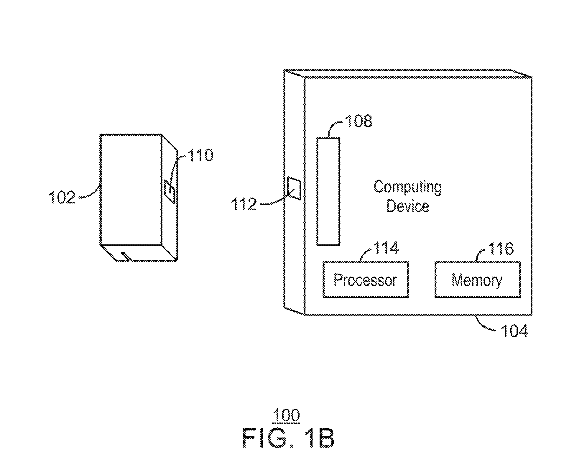
FIG. 1B is a side perspective vie of the peripheral device 102 and the computing device 104, in accordance with examples. The peripheral device 102 includes a device communication port 110. Correspondingly, the computing device 104 includes a computer communication port 112. The device communication port 110 and the computer communication port 112 may utilize any number of communications protocols, proprietary, industry-standard, and so on. For example, the device communication port 110 and the computer communication port 112 may be Universal Serial Bus (USB) ports. When connected, the device communication port 110 is connected with the computer communication port 112. The computing device 104 also includes a processor 114, and a system memory 116. The processor 114 executes computer instructions stored in system memory 116.
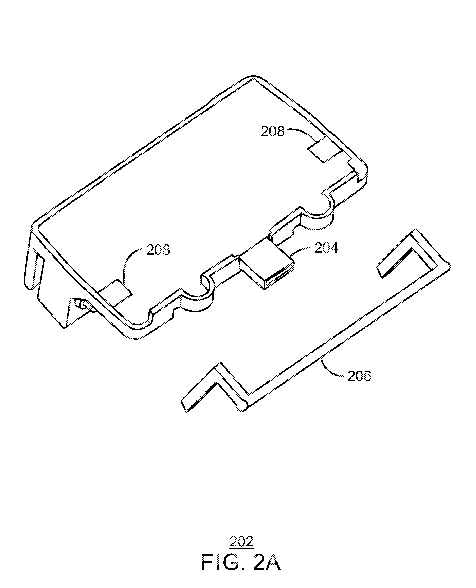
FIG. 2A is a back perspective view of a magnetic card reading peripheral device 202 and cross-bar lever 206, in accordance with examples. The device 202 includes USB communication port 204 and lever attachments 208. The lever attachments 208 may provide a receptacle for securing the cross-bar level 206 to the device 202. In one example, the attachments 208 may include springs (not shown) that provide a range of motion for the device 202 in relation to the cross-bar lever 206. Additionally, such springs may return the device 202 to a position for connecting the device 202 to an example computing device 104.
All peripheral devices 102 have electromagnetic compatibility (EMC) regulations with which to conform. These regulations enable the safe operation of electronic devices, and require that electronic devices provide a ground metal contact. Currently, the screws used to secure typical peripheral devices also provide this ground metal contact. However, example peripheral devices 102 do not include screws to secure the peripheral device 102 to the computing device. Accordingly, example peripheral devices 102 provide ground metal contact without the use of screws. Instead of screws, peripheral devices 102 include a ground retention clip that provide ground metal contacts between the peripheral device 202 and the computing device 104. The ground retention clip is described in greater detail with respect to FIGS. 2B, 2C, and 3.
FIG. 2B is a front perspective view of the device 202, in accordance with examples. The device 202 includes the USB port 204 and ground metal contacts 210. When the peripheral device 202 is connected, the ground metal contacts 210 provide contact between the computing device 104 and a chassis of the peripheral device. The ground metal contacts 210 are exposed surfaces of the ground retention clip, which is secured within the device 202.
FIG. 2C is a bottom perspective view of the device 202 with covering removed, in accordance with examples. The device includes a ground retention clip, secured to, and in contact with, the chassis of the device 202. The surface of the ground retention clip is exposed through an opening, providing the ground metal contacts 210.
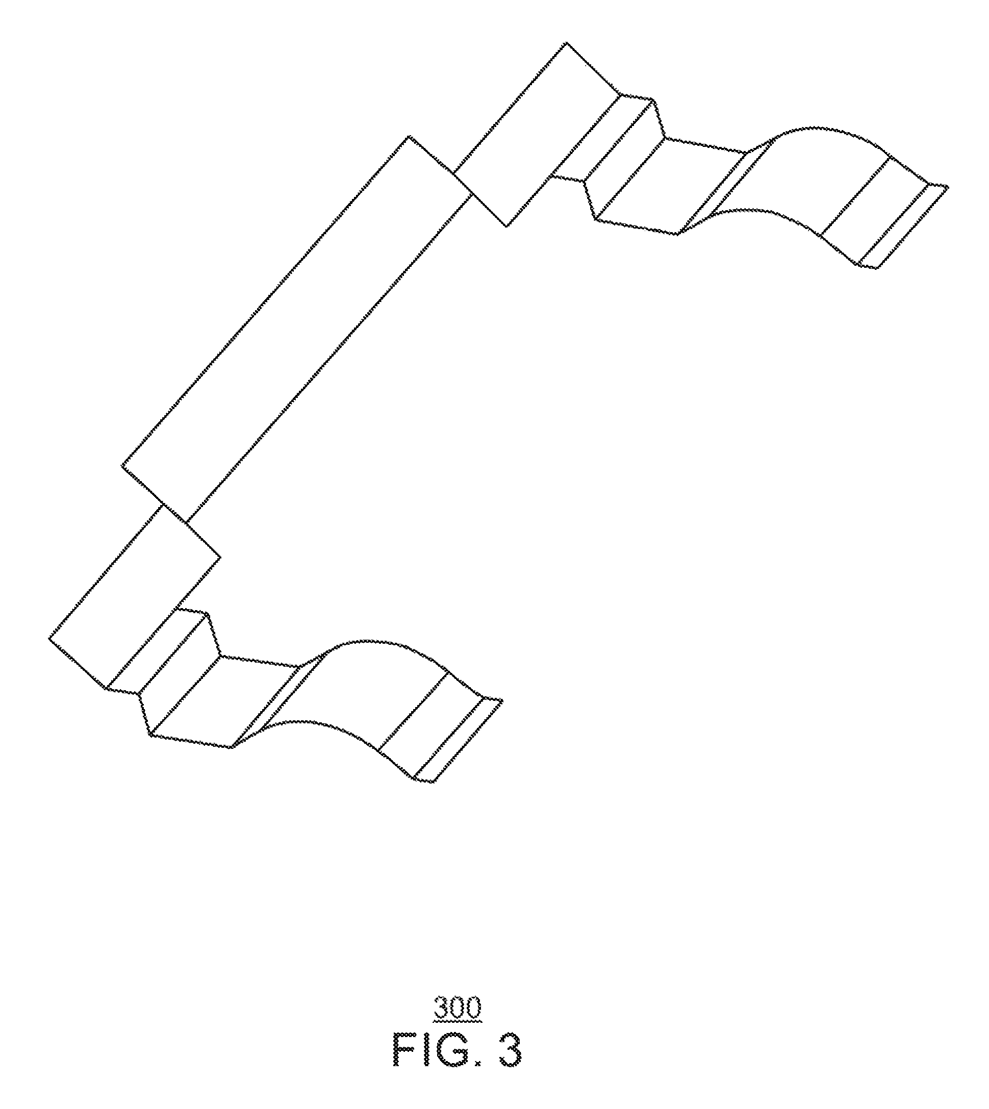
FIG. 3 is a block diagram of an example ground retention clip 300, in accordance with examples. Example peripheral devices 102 may include a ground retention clip 300 to provide grounding contact with a connected computing device 104. The ground retention clip 300 is installed within the peripheral device 102 such that the clip 300 is in electrical contact with the chassis of the peripheral device 102. Additionally, once installed in the peripheral device 102, a portion of the clip 300 is externally exposed to provide the electrical contacts to the computing device 104. It is noted that examples of the claimed subject matter are not limited to the design shown in FIG. 3. Rather, the ground retention clip 300 may be of any shape that, when installed, provides electrical contact with the chassis, and electric contact with the computing device 104, once secured.
Advantageously, a tool is not needed to connect or disconnect example peripheral devices. This tool-less technique enables suppliers and resellers of connected devices 102, 104 to reduce the time for assembly. This time savings translates to cost savings. Original design manufacturers, suppliers and resellers, who sell connected peripheral and computing devices, can save expenses in assembling example systems. In addition, faster service repair and replacement is possible with example systems because the peripheral devices 102 can be disconnected without tools.
While the present techniques may be susceptible to various modifications and alternative forms, the exemplary examples discussed above have been shown only by way of example. It is to be understood that the technique is not intended to be limited to the particular examples disclosed herein. Indeed, the present techniques include all alternatives, modifications, and equivalents falling within the true spirit and scope of the appended claims.
* * * * *
D00000
D00001
D00002
D00003
D00004
D00005
D00006
XML
uspto.report is an independent third-party trademark research tool that is not affiliated, endorsed, or sponsored by the United States Patent and Trademark Office (USPTO) or any other governmental organization. The information provided by uspto.report is based on publicly available data at the time of writing and is intended for informational purposes only.
While we strive to provide accurate and up-to-date information, we do not guarantee the accuracy, completeness, reliability, or suitability of the information displayed on this site. The use of this site is at your own risk. Any reliance you place on such information is therefore strictly at your own risk.
All official trademark data, including owner information, should be verified by visiting the official USPTO website at www.uspto.gov. This site is not intended to replace professional legal advice and should not be used as a substitute for consulting with a legal professional who is knowledgeable about trademark law.