Columnar air moving devices, systems and methods
Avedon Ja
U.S. patent number 10,184,489 [Application Number 15/969,464] was granted by the patent office on 2019-01-22 for columnar air moving devices, systems and methods. This patent grant is currently assigned to Airius IP Holdings, LLC. The grantee listed for this patent is AIRIUS IP HOLDINGS, LLC. Invention is credited to Raymond B. Avedon.


View All Diagrams
| United States Patent | 10,184,489 |
| Avedon | January 22, 2019 |
| **Please see images for: ( Certificate of Correction ) ** |
Columnar air moving devices, systems and methods
Abstract
An air moving device includes a housing member, a rotary fan assembly, and a nozzle. The air moving device further includes a light source member mounted within the nozzle. The light source member can be placed within a flow of air moving out the end of the nozzle in a generally columnar pattern. The flow of air can be used to cool the light source member. A portion of the nozzle can be transparent, allowing the light from the light source member to emanate radially, as well as longitudinally.
| Inventors: | Avedon; Raymond B. (Boulder, CO) | ||||||||||
|---|---|---|---|---|---|---|---|---|---|---|---|
| Applicant: |
|
||||||||||
| Assignee: | Airius IP Holdings, LLC
(Longmont, CO) |
||||||||||
| Family ID: | 46321505 | ||||||||||
| Appl. No.: | 15/969,464 | ||||||||||
| Filed: | May 2, 2018 |
Prior Publication Data
| Document Identifier | Publication Date | |
|---|---|---|
| US 20180320707 A1 | Nov 8, 2018 | |
Related U.S. Patent Documents
| Application Number | Filing Date | Patent Number | Issue Date | ||
|---|---|---|---|---|---|
| 15136541 | Apr 22, 2016 | 9970457 | |||
| 13517578 | May 10, 2016 | 9335061 | |||
| 61497448 | Jun 15, 2011 | ||||
| 61521270 | Aug 8, 2011 | ||||
| Current U.S. Class: | 1/1 |
| Current CPC Class: | F04D 29/545 (20130101); F04D 29/547 (20130101); F04D 25/06 (20130101); F21V 29/673 (20150115); F04D 25/08 (20130101); F04D 29/522 (20130101); F24F 13/078 (20130101); F04D 25/088 (20130101); F04D 29/002 (20130101); F21V 33/0088 (20130101); F04D 29/542 (20130101); F24F 7/065 (20130101); F04D 29/325 (20130101); F21S 8/026 (20130101); F21S 8/06 (20130101) |
| Current International Class: | F24F 7/06 (20060101); F04D 29/54 (20060101); F04D 29/52 (20060101); F04D 29/32 (20060101); F04D 29/00 (20060101); F04D 25/08 (20060101); F04D 25/06 (20060101); F21V 29/67 (20150101); F24F 13/078 (20060101) |
| Field of Search: | ;362/96,149,373 |
References Cited [Referenced By]
U.S. Patent Documents
| 866292 | September 1907 | Meston |
| 917206 | April 1909 | Watts |
| 1053025 | February 1913 | Goodwin |
| 1858067 | May 1932 | Warren |
| 1877347 | September 1932 | McCurdie |
| 1926795 | September 1933 | Sassenberg |
| 2016778 | October 1935 | Hall et al. |
| 2142307 | January 1939 | De Mey et al. |
| 2144035 | January 1939 | Smith, Jr. |
| 2154313 | April 1939 | McMahan |
| 2189008 | February 1940 | Kurth |
| 2189502 | February 1940 | Johnston |
| 2232573 | February 1941 | Teves |
| 2258731 | October 1941 | Blumenthal |
| D133120 | July 1942 | Spear |
| 2359021 | September 1944 | Campbell et al. |
| 2366773 | January 1945 | Eklund et al. |
| 2371821 | March 1945 | Havis |
| D152397 | January 1949 | Damond |
| 2513463 | July 1950 | Eklund et al. |
| 2524974 | October 1950 | Hickmott |
| 2615620 | October 1952 | Goettl |
| 2632375 | March 1953 | Stair et al. |
| 2658719 | November 1953 | Johanson |
| D174230 | March 1955 | Lewis, II |
| 2814433 | November 1957 | Brinen |
| 2830523 | April 1958 | Vehige |
| D187699 | April 1960 | van Rijn |
| 2982198 | May 1961 | Mohrman |
| 3012494 | December 1961 | Drummond |
| 3036509 | May 1962 | Babbitt |
| 3068341 | December 1962 | Ortiz et al. |
| 3072321 | January 1963 | King, Jr. |
| D195287 | May 1963 | Downing |
| 3099949 | August 1963 | Davidson |
| 3165294 | January 1965 | Anderson |
| 3188007 | June 1965 | Myklebust |
| 3212425 | October 1965 | Lindner et al. |
| 3246699 | April 1966 | Jocz |
| 3300123 | January 1967 | Freyholdt et al. |
| 3306179 | February 1967 | Lambie et al. |
| 3320869 | May 1967 | Schach |
| 3364839 | January 1968 | Sweeney et al. |
| 3382791 | May 1968 | Henry-Biabaud |
| 3386368 | June 1968 | Fielding |
| 3413905 | December 1968 | Johnson |
| 3524399 | August 1970 | Bohanon |
| 3584968 | June 1971 | Keith |
| 3601184 | August 1971 | Hauville |
| 3690244 | September 1972 | Kallel et al. |
| 3699872 | October 1972 | Kruger |
| 3765317 | October 1973 | Lowe |
| 3785271 | January 1974 | Joy |
| 3827342 | August 1974 | Hughes |
| 3835759 | September 1974 | Lloyd |
| 3876331 | April 1975 | DenHerder et al. |
| 3927300 | December 1975 | Wada et al. |
| 3932054 | January 1976 | McKelvey |
| 3934494 | January 1976 | Butler |
| 3967927 | July 1976 | Patterson |
| 3973479 | August 1976 | Whiteley |
| 3988973 | November 1976 | Honmann |
| 4006673 | February 1977 | Meyer et al. |
| 4064427 | December 1977 | Hansen et al. |
| 4123197 | October 1978 | Keem et al. |
| D251851 | May 1979 | Palm |
| 4152973 | May 1979 | Peterson |
| 4185545 | January 1980 | Rusth et al. |
| D255488 | June 1980 | Kanarek |
| D256273 | August 1980 | Townsend et al. |
| 4261255 | April 1981 | Anderson et al. |
| 4321659 | March 1982 | Wheeler |
| 4344112 | August 1982 | Brown |
| 4396352 | August 1983 | Pearce |
| 4473000 | September 1984 | Perkins |
| 4512242 | April 1985 | Bohanon, Sr. |
| 4515538 | May 1985 | Shih |
| 4522255 | June 1985 | Baker |
| 4524679 | June 1985 | Lyons |
| 4546420 | October 1985 | Wheeler et al. |
| 4548548 | October 1985 | Gray, III |
| 4550649 | November 1985 | Zambolin |
| 4630182 | December 1986 | Moroi et al. |
| 4657483 | April 1987 | Bede |
| 4662912 | May 1987 | Perkins |
| 4678410 | July 1987 | Kullen |
| 4681024 | July 1987 | Ivey |
| 4692091 | September 1987 | Ritenour |
| 4715784 | December 1987 | Mosiewicz |
| 4716818 | January 1988 | Brown |
| 4730551 | March 1988 | Peludat |
| 4790863 | December 1988 | Nobiraki et al. |
| 4794851 | January 1989 | Kurrle |
| 4796343 | January 1989 | Wing |
| 4848669 | July 1989 | George |
| 4850265 | July 1989 | Raisanen |
| 4890547 | January 1990 | Wagner et al. |
| 4895065 | January 1990 | Lamparter |
| D308416 | June 1990 | Brumbach |
| 4930987 | June 1990 | Stahl |
| 4971143 | November 1990 | Hogan |
| 4973016 | November 1990 | Hertenstein |
| 5000081 | March 1991 | Gilmer |
| 5021932 | June 1991 | Ivey |
| 5033711 | July 1991 | Gregorich et al. |
| 5042366 | August 1991 | Panetski et al. |
| 5078574 | January 1992 | Olsen |
| 5094676 | March 1992 | Karbacher |
| D325628 | April 1992 | Cho |
| 5107755 | April 1992 | Leban et al. |
| 5121675 | June 1992 | Muller et al. |
| 5127876 | July 1992 | Howe et al. |
| 5152606 | October 1992 | Borraccia et al. |
| 5156568 | October 1992 | Ricci |
| 5191618 | March 1993 | Hisey |
| D340765 | October 1993 | Joss et al. |
| 5251461 | October 1993 | Fallows, III et al. |
| 5328152 | July 1994 | Castle |
| 5358443 | October 1994 | Mitchell et al. |
| 5399119 | March 1995 | Birk et al. |
| 5429481 | July 1995 | Liu |
| 5439349 | August 1995 | Kupferberg |
| 5439352 | August 1995 | Line |
| 5443625 | August 1995 | Schaffhausen |
| 5458505 | October 1995 | Prager |
| 5462484 | October 1995 | Jung et al. |
| 5466120 | November 1995 | Takeuchi et al. |
| 5511942 | April 1996 | Meier |
| 5513953 | May 1996 | Hansen |
| 5520515 | May 1996 | Bailey et al. |
| 5545241 | August 1996 | Vanderauwera et al. |
| 5547343 | August 1996 | Jane et al. |
| 5551841 | September 1996 | Kamada |
| 5561952 | October 1996 | Damron |
| 5569019 | October 1996 | Katariya et al. |
| 5584656 | December 1996 | Rose |
| 5595068 | January 1997 | Amr |
| 5613833 | March 1997 | Wolfe et al. |
| 5658196 | August 1997 | Swaim |
| 5664872 | September 1997 | Spearman et al. |
| 5709458 | January 1998 | Metz |
| 5725356 | March 1998 | Carter |
| 5791985 | August 1998 | Schiedegger et al. |
| 5822186 | October 1998 | Bull |
| 5918972 | July 1999 | Van Belle |
| 5934783 | August 1999 | Yoshikawa |
| D414550 | September 1999 | Bloom |
| 5947816 | September 1999 | Schiedegger et al. |
| 5967891 | October 1999 | Riley et al. |
| 5997253 | December 1999 | Fechan |
| 6004097 | December 1999 | Wark et al. |
| 6068385 | May 2000 | Hsieh |
| 6095671 | August 2000 | Hutain |
| 6109874 | August 2000 | Steiner |
| 6145798 | November 2000 | Janisse et al. |
| 6149513 | November 2000 | Lyu |
| 6155782 | December 2000 | Hsu |
| 6168517 | January 2001 | Cook |
| 6176680 | January 2001 | Ringblom et al. |
| 6183203 | February 2001 | Grintz |
| 6192702 | February 2001 | Shimogori |
| 6196915 | March 2001 | Schiedegger et al. |
| 6319304 | November 2001 | Moredock |
| D453960 | February 2002 | Shelby et al. |
| 6352473 | March 2002 | Clark |
| 6360816 | March 2002 | Wagner |
| 6361428 | March 2002 | Tosconi et al. |
| 6361431 | March 2002 | Kawano |
| 6364760 | April 2002 | Rooney |
| 6382911 | May 2002 | Beltowski |
| 6383072 | May 2002 | Schiedegger et al. |
| 6384494 | May 2002 | Avidano et al. |
| 6386828 | May 2002 | Davis et al. |
| 6386970 | May 2002 | Vernier, II et al. |
| 6386972 | May 2002 | Schiedegger et al. |
| 6435964 | August 2002 | Chang |
| 6451080 | September 2002 | Rocklitz et al. |
| 6458028 | October 2002 | Snyder |
| 6458628 | October 2002 | Distefano et al. |
| 6484524 | November 2002 | Ulanov |
| 6551185 | April 2003 | Miyake et al. |
| 6575011 | June 2003 | Busby et al. |
| 6581974 | June 2003 | Ragner et al. |
| 6582291 | June 2003 | Clark |
| 6592328 | July 2003 | Cahill |
| 6595747 | July 2003 | Bos |
| 6626003 | September 2003 | Kortum et al. |
| 6626636 | September 2003 | Bohn |
| D481101 | October 2003 | Boehrs et al. |
| D481159 | October 2003 | Walker |
| 6648752 | November 2003 | Vernier, II et al. |
| 6679433 | January 2004 | Gordon et al. |
| 6682308 | January 2004 | Fei et al. |
| 6700266 | March 2004 | Winkel et al. |
| 6761531 | July 2004 | Toye |
| 6767281 | July 2004 | McKee |
| 6783578 | August 2004 | Tillman, Jr. |
| 6804627 | October 2004 | Marokhovsky et al. |
| 6805627 | October 2004 | Marts et al. |
| 6812849 | November 2004 | Ancel |
| 6886270 | May 2005 | Gilmer |
| 6916240 | July 2005 | Morton |
| 6938631 | September 2005 | Gridley |
| 6951081 | October 2005 | Bonshor |
| 6966830 | November 2005 | Hurlstone et al. |
| 6974381 | December 2005 | Walker et al. |
| D514688 | February 2006 | Avedon |
| 7011500 | March 2006 | Matson |
| 7011578 | March 2006 | Core |
| 7044849 | May 2006 | Dippel |
| 7048499 | May 2006 | Mathson et al. |
| 7056092 | June 2006 | Stahl |
| 7056368 | June 2006 | Moredock et al. |
| 7101064 | September 2006 | Ancel |
| 7152425 | December 2006 | Han et al. |
| 7166023 | January 2007 | Haigh et al. |
| 7175309 | February 2007 | Craw et al. |
| 7185504 | March 2007 | Kasai et al. |
| 7201110 | April 2007 | Pawlak |
| 7201650 | April 2007 | Demerath et al. |
| 7214035 | May 2007 | Bussieres et al. |
| 7246997 | July 2007 | Liu et al. |
| 7288023 | October 2007 | Leopold |
| 7311492 | December 2007 | Ostberg |
| 7320636 | January 2008 | Seliger et al. |
| 7331764 | February 2008 | Reynolds et al. |
| D567930 | April 2008 | Smith |
| 7374408 | May 2008 | Savage et al. |
| D570981 | June 2008 | McClelland |
| 7381129 | June 2008 | Avedon |
| 7467931 | December 2008 | O'Toole |
| 7473074 | January 2009 | Herbst et al. |
| 7476079 | January 2009 | Bartlett |
| 7497773 | March 2009 | Schmidt |
| 7516578 | April 2009 | Bonshor |
| 7544124 | June 2009 | Polston |
| 7549258 | June 2009 | Lajewski |
| 7566034 | July 2009 | Bonshor |
| D599471 | September 2009 | Borovicka et al. |
| 7607935 | October 2009 | Dahl |
| 7610726 | November 2009 | Lajewski |
| D605332 | December 2009 | Miranda |
| 7645188 | January 2010 | Peerbolt |
| 7651390 | January 2010 | Profeta et al. |
| 7677770 | March 2010 | Mazzochette |
| 7677964 | March 2010 | Bucher et al. |
| 7708625 | May 2010 | Leseman et al. |
| D617890 | June 2010 | Thomas |
| D620096 | July 2010 | Underwood |
| 7748954 | July 2010 | Eguchi et al. |
| 7752814 | July 2010 | Bonshor |
| 7774999 | August 2010 | McKee |
| 7780510 | August 2010 | Polston |
| D631148 | January 2011 | Benton et al. |
| 7901278 | March 2011 | O'Hagin |
| 7930858 | April 2011 | Lajewski |
| 8052386 | November 2011 | Fitzpatrick et al. |
| D672863 | December 2012 | Romero Carreras |
| 8366387 | February 2013 | Reuter |
| D681184 | April 2013 | Romero Carreras |
| D684307 | June 2013 | Teller |
| 8459846 | June 2013 | Tsao |
| 8487517 | July 2013 | Fang |
| 8529324 | September 2013 | Moredock et al. |
| 8596596 | December 2013 | Naji et al. |
| 8616842 | December 2013 | Avedon |
| D698916 | February 2014 | Avedon |
| 8641375 | February 2014 | Tian et al. |
| D710490 | August 2014 | Shurtleff |
| D715904 | October 2014 | Tate et al. |
| 8894354 | November 2014 | Hodgson et al. |
| 8899930 | December 2014 | Innocenti et al. |
| 8967983 | March 2015 | Kampf |
| 8992174 | March 2015 | Chang |
| 9151295 | October 2015 | Avedon |
| D743521 | November 2015 | Jackson |
| D746971 | January 2016 | Avedon |
| D747453 | January 2016 | Stewart et al. |
| D755438 | May 2016 | Kimmet |
| D756498 | May 2016 | Norman et al. |
| 9335061 | May 2016 | Avedon |
| D758642 | June 2016 | Eguchi |
| D768844 | October 2016 | Koseoglu |
| 9459020 | October 2016 | Avedon |
| D775719 | January 2017 | Smith et al. |
| D783795 | April 2017 | Avedon |
| 9631627 | April 2017 | Avedon |
| 9696026 | July 2017 | Hardgrave |
| 9702576 | July 2017 | Avedon |
| 9714663 | July 2017 | Avedon |
| D805176 | December 2017 | Avedon |
| 9970457 | May 2018 | Avedon |
| D820967 | June 2018 | Avedon |
| 10024531 | July 2018 | Avedon |
| 2001/0049927 | December 2001 | Toepel |
| 2002/0045420 | April 2002 | Tailion |
| 2002/0137454 | September 2002 | Baker |
| 2003/0092373 | May 2003 | Kuo |
| 2004/0050077 | March 2004 | Kasai et al. |
| 2004/0052641 | March 2004 | Chen |
| 2004/0240214 | December 2004 | Whitlow et al. |
| 2004/0253095 | December 2004 | Sasaki et al. |
| 2005/0092888 | May 2005 | Gonce |
| 2005/0159101 | July 2005 | Hrdina et al. |
| 2005/0202776 | September 2005 | Avedon |
| 2006/0087810 | April 2006 | Rockenfeller |
| 2006/0172688 | August 2006 | Johnson |
| 2006/0193139 | August 2006 | Sun |
| 2006/0276123 | December 2006 | Sanagi et al. |
| 2006/0284435 | December 2006 | Vitito |
| 2007/0213003 | September 2007 | Railkar et al. |
| 2007/0231145 | October 2007 | Jin |
| 2007/0246579 | October 2007 | Blateri |
| 2007/0297906 | December 2007 | Wu |
| 2007/0297912 | December 2007 | Reuter |
| 2008/0019836 | January 2008 | Butz et al. |
| 2008/0188175 | August 2008 | Wilkins |
| 2008/0227381 | September 2008 | Avedon |
| 2009/0041580 | February 2009 | Wichmann et al. |
| 2009/0122516 | May 2009 | Yang |
| 2009/0155080 | June 2009 | Yu |
| 2009/0170421 | July 2009 | Adrian et al. |
| 2009/0219727 | September 2009 | Weaver |
| 2009/0262550 | October 2009 | Inoue |
| 2010/0009621 | January 2010 | Hsieh |
| 2010/0052495 | March 2010 | Liu et al. |
| 2010/0075588 | March 2010 | Haneline |
| 2010/0176706 | July 2010 | Fu et al. |
| 2010/0192611 | August 2010 | Yamaguchi et al. |
| 2010/0202932 | August 2010 | Danville |
| 2010/0232168 | September 2010 | Horng |
| 2010/0266400 | October 2010 | Avedon |
| 2010/0295436 | November 2010 | Horng |
| 2010/0328881 | December 2010 | Huang |
| 2011/0037368 | February 2011 | Huang |
| 2011/0057551 | March 2011 | Lee et al. |
| 2011/0057552 | March 2011 | Weaver |
| 2011/0080096 | April 2011 | Dudik et al. |
| 2011/0084586 | April 2011 | Lain et al. |
| 2011/0133622 | June 2011 | Mo et al. |
| 2011/0140588 | June 2011 | Chen |
| 2011/0223016 | September 2011 | Ediger et al. |
| 2012/0062095 | March 2012 | Horng |
| 2012/0194054 | August 2012 | Johnston |
| 2012/0195749 | August 2012 | Avedon |
| 2013/0011254 | January 2013 | Avedon |
| 2013/0196588 | August 2013 | Liao |
| 2014/0314560 | October 2014 | Avedon |
| 2015/0176834 | June 2015 | Avedon |
| 2015/0176851 | June 2015 | Avedon |
| 2015/0354578 | December 2015 | Avedon |
| 2016/0146222 | May 2016 | Avedon |
| 2016/0186765 | June 2016 | Avedon |
| 2017/0370363 | December 2017 | Avedon |
| 2018/0149161 | May 2018 | Avedon |
| 2018/0149380 | May 2018 | Avedon |
| 2013203632 | Nov 2016 | AU | |||
| 1426729 | Jul 2003 | CN | |||
| 101592328 | Dec 2009 | CN | |||
| 201560963 | Aug 2010 | CN | |||
| 44 13 542 | Oct 1995 | DE | |||
| 196 38 518 | Apr 1998 | DE | |||
| 10 2008 044874 | Mar 2010 | DE | |||
| 0 037 958 | Oct 1981 | EP | |||
| 0 212 749 | Mar 1987 | EP | |||
| 0 772 007 | May 1997 | EP | |||
| 2 248 692 | Nov 2010 | EP | |||
| 2 721 350 | Apr 2014 | EP | |||
| 2 721 352 | Apr 2014 | EP | |||
| 0 715 101 | Nov 1931 | FR | |||
| 2 784 423 | Apr 2000 | FR | |||
| 0 792 369 | Mar 1958 | GB | |||
| 0 824 390 | Nov 1959 | GB | |||
| 0 981 188 | Jan 1965 | GB | |||
| 1 251 880 | Nov 1971 | GB | |||
| 2 344 619 | Jun 2000 | GB | |||
| 2 468 504 | Sep 2010 | GB | |||
| 55-032965 | Mar 1980 | JP | |||
| 61-502267 | Oct 1986 | JP | |||
| 01-067548 | Mar 1989 | JP | |||
| 07-167097 | Jul 1995 | JP | |||
| 07-253231 | Oct 1995 | JP | |||
| 08-219939 | Aug 1996 | JP | |||
| 11-132543 | May 1999 | JP | |||
| 2001-193979 | Jul 2001 | JP | |||
| 2002-349489 | Dec 2002 | JP | |||
| 2006-350237 | Dec 2006 | JP | |||
| 2010-181124 | Aug 2010 | JP | |||
| 20-0176664 | Apr 2000 | KR | |||
| 2003-0025428 | Mar 2003 | KR | |||
| 10-1255739 | Apr 2013 | KR | |||
| 2400254 | Sep 2010 | RU | |||
| M337636 | Aug 2008 | TW | |||
| WO 01/034983 | May 2001 | WO | |||
| WO 2005/091896 | Oct 2005 | WO | |||
| WO 2006/078102 | Jul 2006 | WO | |||
| WO 2008/062319 | May 2008 | WO | |||
| WO 2010/046536 | Apr 2010 | WO | |||
| WO 2010/114702 | Oct 2010 | WO | |||
| WO 2011/067430 | Jun 2011 | WO | |||
| WO 2012/174155 | Dec 2012 | WO | |||
| WO 2012/174156 | Dec 2012 | WO | |||
| WO 2015/187856 | Dec 2015 | WO | |||
| WO 2016/081693 | May 2016 | WO | |||
Other References
|
"Airius Model R20 EC `Eyeball` Data Sheet", http://airius.com.au/products/new-retail-series-2/attachment/na_std_retai- lseries/ published Jun. 15, 2016 as printed May 23, 2017 in 1 page. cited by applicant . Keeler-Hardware, "OC Oval Cylinder Escutcheon", https://www.keelerhardware.com.au/products/oc-oval-cylinder-escutcheon, as printed Nov. 13, 2017 in 3 pages. cited by applicant . "The New Airius Q50 Ec", https://web.archive.org/web/20150721185407/http://airius.com.au/technical- /specification-sheets/the-new-airius-q50-ec/ as archived Jul. 21, 2015, pp. 2. cited by applicant. |
Primary Examiner: Harris; William N
Attorney, Agent or Firm: Knobbe Martens Olson & Bear LLP
Parent Case Text
CROSS-REFERENCE TO RELATED APPLICATIONS
This application is a continuation of U.S. patent application Ser. No. 15/136,541, filed Apr. 22, 2016, which is a continuation of U.S. patent application Ser. No. 13/517,578, filed Jun. 13, 2012, which claims the benefit under 35 U.S.C. .sctn. 119(e) to U.S. Provisional Patent Application No. 61/497,448, filed Jun. 15, 2011, and to U.S. Provisional Patent Application No. 61/521,270, filed Aug. 8, 2011, each of which is incorporated in its entirety by reference herein.
This application is related to U.S. Provisional Patent Application No. 61/497,422, entitled Columnar Air Moving Devices, Systems and Methods, filed Jun. 15, 2011, and to U.S. Provisional Patent Application No. 61/497,446, entitled Columnar Air Moving Devices, Systems and Methods, filed Jun. 15, 2011, each of which is incorporated in its entirety by reference herein. This application is also related to U.S. patent application Ser. No. 12/130,909, filed May 30, 2008, and to U.S. patent application Ser. No. 12/724,799, filed Mar. 16, 2010, each of which is incorporated in its entirety by reference herein.
Claims
What is claimed is:
1. An air moving device comprising: an outer housing having an outlet and an annular interior wall therein defining an interior space extending axially to the outlet; a plurality of stators extending axially through the interior space; an impeller configured to move air along a first flow path extending through the interior space to the outlet; and an inner housing located downstream of the impeller, the inner housing having: an inside chamber defining a second flow path extending axially through the inside chamber to the outlet, an upstream opening configured to divert some of the moving air from the first flow path to the second flow path; and a light source positioned downstream of the inside chamber within the second flow path.
2. The air moving device of claim 1, wherein a top of the annular interior wall is positioned downstream of the impeller.
3. The air moving device of claim 1, wherein the light source comprises an LED.
4. The air moving device of claim 1, wherein the annular interior wall has a venturi section.
5. The air moving device of claim 1, wherein the inside chamber has an hourglass profile.
6. The air moving device of claim 1, wherein the plurality of stators are positioned within the interior space equidistantly in a circumferential pattern.
7. The air moving device of claim 1, wherein the annular interior wall is surrounded by the plurality of stators.
8. The air moving device of claim 1, wherein the plurality of stators are positioned radially outward from the light source.
9. The air moving device of claim 1, wherein the plurality of stators extend completely through the interior space to the outlet.
Description
BACKGROUND OF THE INVENTIONS
Field of the Inventions
The present application relates generally to systems, devices and methods for moving air that are particularly suitable for creating air temperature de-stratification within a room, building, or other structure.
Description of the Related Art
The rise of warm air and the sinking of cold air can create significant variation in air temperatures between the ceiling and floor of buildings with conventional heating, ventilation and air conditioning systems. Air temperature stratification is particularly problematic in large spaces with high ceilings such as warehouses, gymnasiums, offices, auditoriums, hangers, commercial buildings, residences with cathedral ceilings, agricultural buildings, and other structures, and can significantly increase heating and air conditioning costs. Structures with both low and high ceiling rooms can often have stagnant or dead air, as well, which can further lead to air temperature stratification problems.
One proposed solution to air temperature stratification is a ceiling fan. Ceiling fans are relatively large rotary fans, with a plurality of blades, mounted near the ceiling. The blades of a ceiling fan have a flat or airfoil shape. The blades have a lift component that pushes air upwards or downwards, depending on the direction of rotation, and a drag component that pushes the air tangentially. The drag component causes tangential or centrifugal flow so that the air being pushed diverges or spreads out. Conventional ceiling fans are generally ineffective as an air de-stratification device in relatively high ceiling rooms because the air pushed by conventional ceiling fans is not maintained in a columnar pattern from the ceiling to the floor, and often disperses or diffuses well above the floor.
Another proposed solution to air temperature stratification is a fan connected to a vertical tube that extends substantially from the ceiling to the floor. The fan can be mounted near the ceiling, near the floor or in between. This type of device can push cooler air up from the floor to the ceiling or warmer air down from the ceiling to the floor. Such devices, when located away from the walls in an open space in a building, interfere with floor space use and are not aesthetically pleasing. When confined to locations only along the walls of an open space, such devices may not effectively circulate air near the center of the open space. Examples of fans connected to vertical tubes are disclosed in U.S. Pat. No. 3,827,342 to Hughes, and U.S. Pat. No. 3,973,479 to Whiteley.
A more practical solution is a device, for example, with a rotary fan that minimizes a rotary component of an air flow while maximizing axial air flow quantity and velocity, thereby providing a column of air that flows from a high ceiling to a floor in a columnar pattern with minimal lateral dispersion without a physical transporting tube. Examples of this type of device are described in U.S. patent application Ser. No. 12/130,909, filed May 30, 2008, and U.S. patent application Ser. No. 12/724,799, filed Mar. 16, 2010, each of which is incorporated in its entirety by reference herein.
Fan and light combinations are also known. For example, ceiling fans often have light members positioned below the ceiling fan, used to help illuminate a room. Additionally, can lights, placed individually in ceiling structures of bathrooms, kitchens, and other residential rooms are also known. These can lights can sometimes include a fan member for ventilation purposes. Sometimes the fan member can be used to cool a recessed lighting. Examples can be found in U.S. Pat. No. 7,607,935, or U.S. Pat. No. 6,095,671.
SUMMARY OF THE INVENTION
An aspect of at least one of the embodiments disclosed herein includes the realization that light source members (e.g. LED light engines) mounted within the ceiling structure of a room or building are often susceptible to damage from high levels of heat in the surrounding air. The life expectancy of a light source member can be directly proportional to the level of heat within a building, and especially the level of heat adjacent a ceiling. It has been found, for example, that for some light source members, the life of the light source member decreases by 50% for every 10.degree. F. over 77.degree. F. in the area surrounding the light source member.
Therefore, it would be advantageous to not only have an air de-stratification device that is designed to de-stratify the air in a room and reduce pockets of high temperature near the ceiling, but also to have an air de-stratification device that additionally houses a light source member, and through use of heat exchange during the de-stratification process, keeps the light source member as cool as possible.
Thus, in accordance with at least one embodiment described herein, a columnar air moving device can comprise a housing member forming an interior space within the air moving device, the housing member comprising at least one opening for directing a volume of air into the interior space, a rotary fan assembly mounted within the interior space, the rotary fan assembly comprising an impeller and a plurality of blades for directing a volume of air in a downwardly direction, an elongate nozzle communicating with and extending downwardly from the rotary fan assembly, the elongate nozzle comprising at least one structure for directing the volume of air downwardly out of the air moving device in a generally columnar manner, and a light source member positioned at least partially within the nozzle, the light source member configured to direct light out of the air moving device, the light source member positioned within a flow of the volume of air being directed downwardly through the nozzle and out of the air moving device, and at least one vent structure located between the rotary fan assembly and the bottom of the air moving device.
BRIEF DESCRIPTION OF THE DRAWINGS
These and other features and advantages of the present embodiments will become more apparent upon reading the following detailed description and with reference to the accompanying drawings of the embodiments, in which:
FIG. 1 is a top perspective view of an air moving device in accordance with an embodiment;
FIG. 2 is a front elevation view of the device of FIG. 1;
FIG. 3 is a top plan view of the device of FIG. 1;
FIG. 4 is a bottom plan view of the device of FIG. 1;
FIG. 5 is a perspective, partial view of the device of FIG. 1, taken along line 5-5 in FIG. 2;
FIG. 6 is a perspective, partial view of the device of FIG. 1, taken along line 6-6 in FIG. 2;
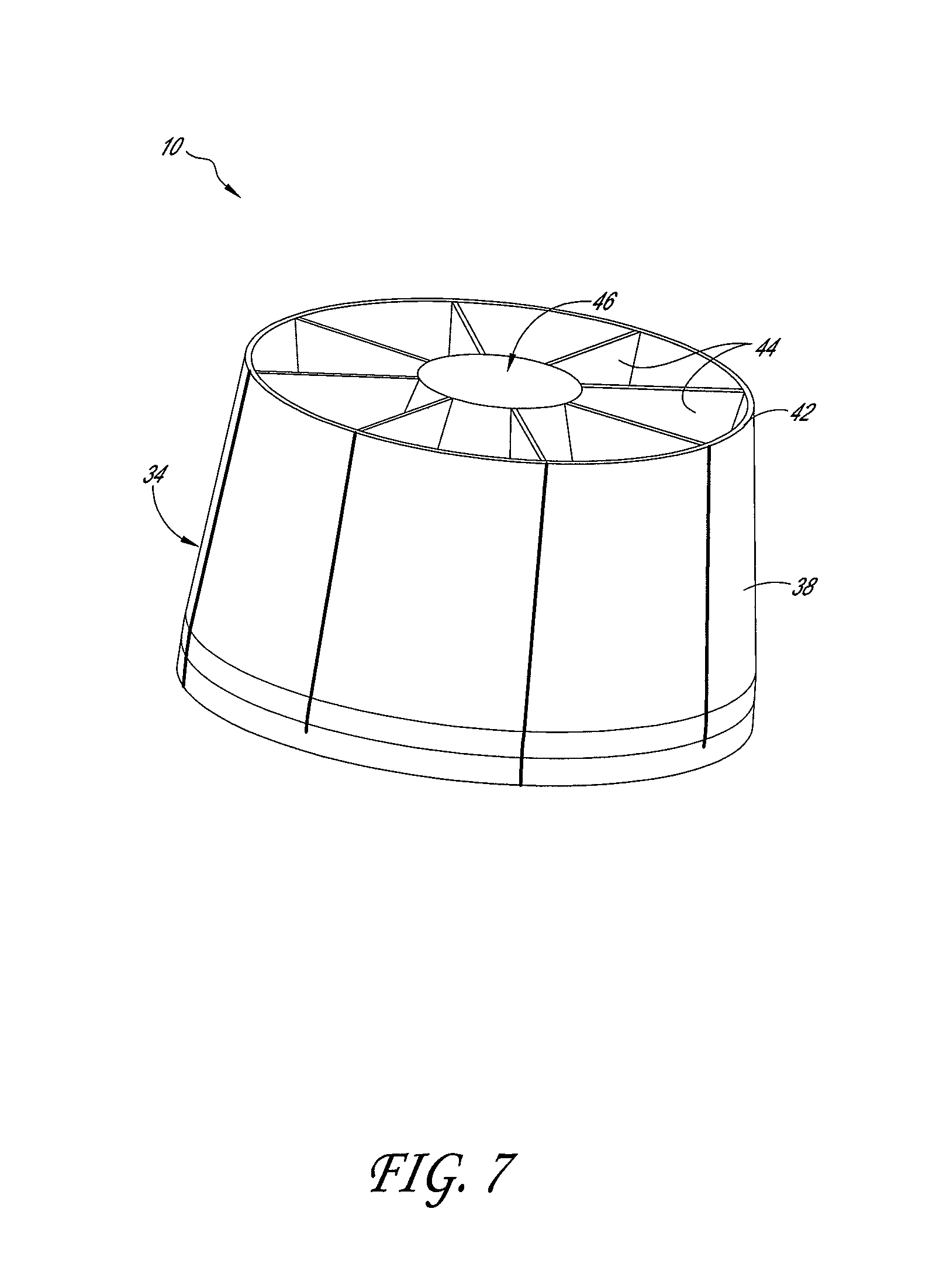
FIG. 7 a perspective, partial view of the device of FIG. 1, taken along line 7-7 in FIG. 2;
FIG. 8 is cross-sectional view of the device of FIG. 1, taken along line 9-9 in FIG. 2;
FIG. 9 is a schematic view of a connection feature between two stator vanes in the air moving device of FIG. 1;
FIG. 10 is a schematic, cross-sectional view of an air moving device according to an embodiment;
FIG. 11 is a schematic view of an air moving device in accordance with an embodiment mounted within a ceiling structure;
FIGS. 12A-F are illustrations of embodiments of light source members with one or more channels therethrough, FIGS. 12A, 12C, and 12E being top perspective views of three different embodiments, and FIGS. 12B, 12D, and 12F being the corresponding bottom plan views thereof;
FIG. 13 is a front, cross-sectional view of an air moving device in accordance with another embodiment;
FIG. 14 is a bottom, cross-sectional perspective view of the air moving device of FIG. 13;
FIG. 15 is a bottom perspective view of the air moving device of FIG. 13; and
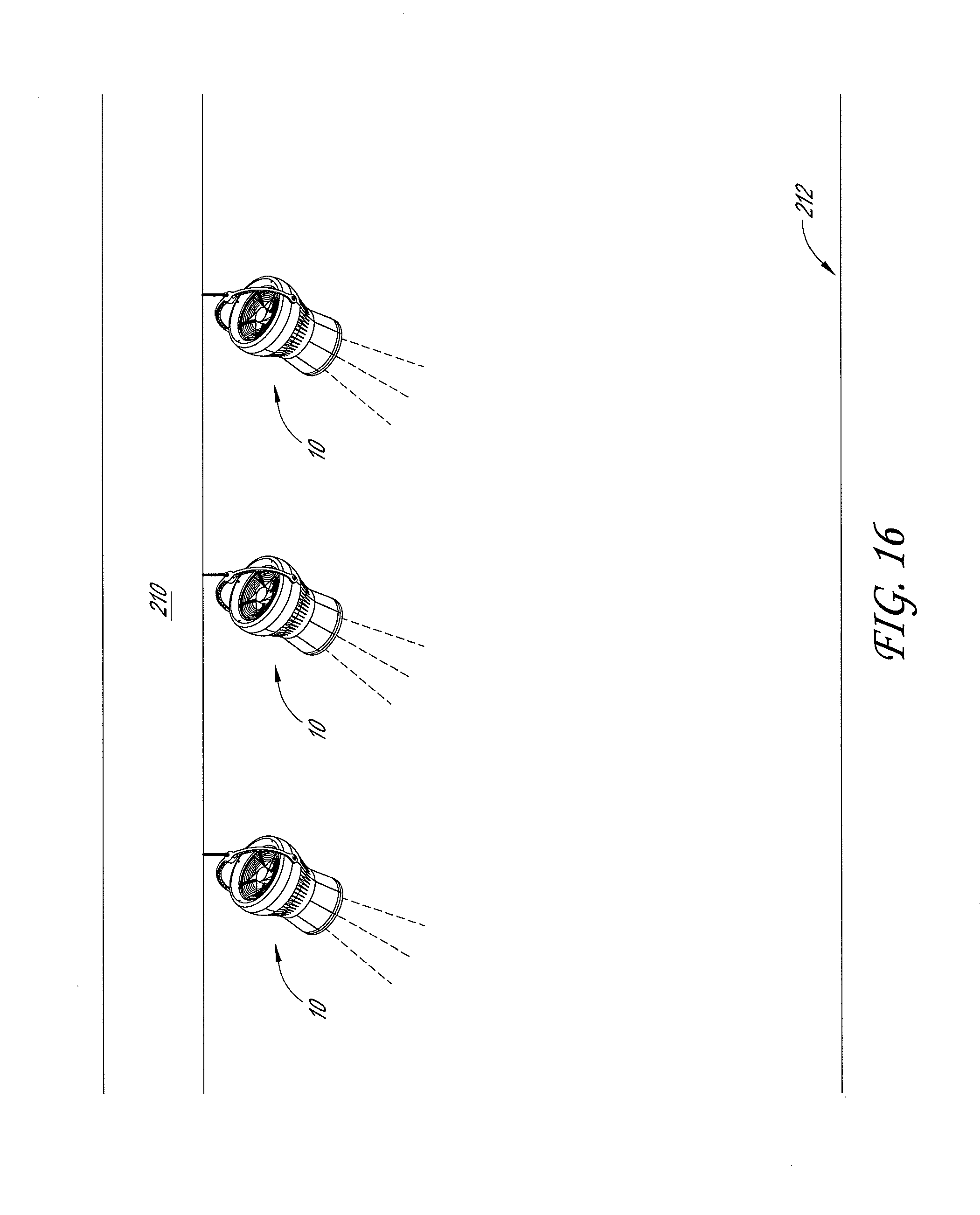
FIG. 16 is a schematic view of cascading air moving devices in a structure.
DETAILED DESCRIPTION OF THE PREFERRED EMBODIMENTS
With reference to FIGS. 1-4, an air moving device 10 can comprise a housing member 12. The housing member 12 can form an outer shell of the air moving device 10, and can at least partially enclose an interior space within the air moving device 10. The housing member 12 can be formed from one or more sections. For example, the housing member 12 can comprise an upper housing section 14, and a lower housing section 16. In some embodiments the upper and lower housing sections 14, 16 can be attached to one other through use of fasteners, adhesive, or other structure. In some embodiments, the upper housing section 14 and lower housing section 16 can be integrally formed as a single piece.
The air moving device 10 can include a support member 18. The support member 18 can be used to support the weight of the air moving device 10, and/or to attach the air moving device 10 to another structure. In some embodiments, the support member 18 can comprise a ring-shaped structure 20 (e.g. an eye-bolt). The support member 18 can extend from the upper housing section 14. The support member 18 can be used, for example, to hang the air moving device 10 from a ceiling structure within a building, for example with wire, string, rope, or other device(s). In some embodiments, the housing member 12 can comprise multiple support members 18.
In some embodiments, the support member 18 can comprise a generally arched structure 22. The arched structure 22 can be connected to the housing member 12 with two ratcheting structures 24 on either side of the air housing member 12. The ratcheting structures 24 can enable the arched structure 22 to be moved (e.g. pivoted) relative to the rest of the housing member 12. This can allow the air moving device 10 to be hung, for example, above a first location on the floor of a room or building, and to be angled such that it directs air to a second, different location on the floor of the room or building.
With continued reference to FIGS. 1-4 and 8, in some embodiments the housing member 12 can comprise a cowling 23 and an intake grill 26. The cowling 23 and intake grill 26 can be configured to direct a volume of air into the interior space of the air moving device 10. For example, the cowling 23 can comprise a structure with a curved profile that extends inwardly into the air moving device 10. The intake grill 26 can sit slightly below the cowling 23. Air from the surrounding environment can be directed over the curved surface of the cowling 23, through the intake grill 26, and down into the interior space of the air moving device 10. The intake grill 26 can inhibit or prevent unwanted debris from entering the interior space of the air moving device 10. Other structures for air intake are also possible, including but not limited to one or more air vents situated on and around the housing member 12.
With reference to FIGS. 5 and 8, the air moving device 10 can comprise a rotary fan assembly 28 mounted within the interior space. The rotary fan assembly 28 can comprise an impeller 30 and a plurality of blades 32. The rotary fan assembly 28 can be configured to direct a volume of air that has entered through the cowling 23 and intake grill 26 downwardly through the air moving device 10. The rotary fan assembly 28 can push, or force, a volume of air downwardly within the interior space of the air moving device 10. The rotary fan assembly 28 can comprise a motor. For example, the impeller 30 itself can house a motor (not shown). The motor can cause the impeller 30 and blades 32 to spin. In some embodiments, the motor can be located elsewhere within the air moving device 10, or located at least partially outside the air moving device 10. The rotary fan assembly 28 can comprise at least one electrical component. In some embodiments, the rotary fan assembly 28 can be mounted to the lower housing section 16.
With continued reference to FIGS. 1-4, the air moving device 10 can comprise a nozzle 34. The nozzle 34 can communicate with and extend downwardly from the housing member 12. In some embodiments, the nozzle 34 is attached to the housing member 12. The nozzle 34 can communicate with and extend downwardly from the rotary fan assembly 28. In some embodiments, the nozzle 34 is attached to the rotary fan assembly 28.
The nozzle 34 can comprise a structure for directing a volume of air out of the air moving device 10. For example, the nozzle 34 can comprise a structure for directing a volume of air out of the air moving device 10 that has previously entered through the cowling 23, intake grill 26, and rotary fan assembly 28.
With reference to FIGS. 1, 2, and 5-8, the nozzle 34 can have multiple sections. For example, the nozzle 34 can comprise a first section 36 extending downwardly from the lower housing section 16, and angled generally inwardly. The nozzle 34 can have a second section 38 located below the first section 36, and angled generally outwardly. In some embodiments, the nozzle 34 can have additional sections.
In some embodiments, the nozzle 34 can include sections that are integrally formed together. For example, the first and second sections 36, 38 can be formed integrally together.
In some embodiments, the nozzle 34 can include sections that are releasably connected together. For example, one or more of the first and second sections 36, 38 can be releasably connected to one another. In some embodiments, the second section 38 can be releasably connected to the first section 36. The connection of the first section 36 to the second section 38 can form a joint 42 around the air moving device 10. In some embodiments, a locking device or mechanism can lock one or more sections of the nozzle 34 together. For example, the first section 36 can be locked together with the second section 38 at the joint 42.
With reference to FIGS. 6-8, the nozzle 34 can comprise at least one stator vane 44. The stator vanes 44 can be positioned equidistantly in a circumferential pattern within the nozzle 34. In some embodiments, eight stator vanes 44 can be used. The stator vanes 44 can direct a volume of air that has entered through the rotary fan assembly 28. The stator vanes 44 can be used to straighten a volume of air within the nozzle 34. The stator vanes 44 can be used to force a volume of air to move in a generally columnar direction downwardly towards the floor of a building or other structure, with minimal lateral dispersion, similar to the devices described for example in U.S. patent application Ser. No. 12/130,909, and U.S. patent application Ser. No. 12/724,799, each of which is incorporated in its entirety by reference herein. In some embodiments, the nozzle 34 can have no stator vanes 44.
In some embodiments, the air moving device 10 can be a self-contained unit, not connected to any ductwork, tubing, or other structure within a room or building. The air moving device 10 can be a stand-alone de-stratification device, configured to de-stratify air within a given space.
In some embodiments, the air moving device 10 can have an overall height (extending from the top of the housing member 12 to the bottom of the nozzle 34) that ranges from between approximately one foot to four feet, though other ranges are also possible. For example, in some embodiments the air moving device 10 can have an overall height that ranges from approximately two feet to three feet. In some embodiments the housing member 12 can have an overall outside diameter that ranges from approximately 8 inches to 30 inches, though other ranges are also possible. For example, in some embodiments the housing member 12 can have an overall outside diameter that ranges from approximately 12 inches to 24 inches. In some embodiments, the nozzle 34 can have an outside diameter that ranges between approximately 5 inches to 12 inches, though other ranges are possible. For example, in some embodiments the nozzle 34 can have an outside diameter that ranges from between approximately 8 to 10 inches. In embodiments for example where a light source member 46 is included in the nozzle 34, the nozzle 34 can have an outside diameter that ranges from 20 inches to 28 inches, though other diameters are also possible. In some embodiments the air moving device 10 can have a motor with an overall power that ranges between approximately 720 and 760 watts, though other ranges are possible. In some embodiments the air moving device 10 can have a motor with an overall power that is approximately 740 watts (i.e. about 1.0 hp).
With reference to FIGS. 4, 7, 8, and 10, the air moving device 10 can comprise at least one light source member 46. The light source member 46 can be positioned at least partially within the nozzle 34. The light source member 46 can comprise any of a variety of light sources, including but not limited to an LED light source, and/or a lamp. In some embodiments, the light source member 46 can comprise a bulb and/or lens. The light source member 46 can be attached to the nozzle 34. The light source member 46 can fit within a recess formed within the nozzle 34. The light source member 46 can be configured to direct light out of the air moving device 10. For example, the light source member can be configured to direct light out of a bottom of the nozzle 34.
In some embodiments, the light source member 46 can be mounted within a section of the nozzle 34. For example, the light source member 46 can be mounted within the plurality of stator vanes 44. In some embodiments, the stator vanes 44 can include cut-out portions configured to form a cavity or opening for insertion of the light source member 46. The light source member 46 can rest on top the stator vanes 44 within the nozzle 34, without being securely attached to the nozzle 34. In some embodiments, the light source member 46 can be positioned within the nozzle 34 such that stator vanes 44 are located directly above and directly below the light source member 46.
With continued reference to FIG. 8, and as described above, at least a portion of the nozzle 34 can be removed and/or replaced. For example, the second section 38 can be removed from the air moving device 10, so that the light source member 46 can be taken out and replaced with a different light source member 46. In some embodiments, an entire portion of the nozzle 34 can be removed and replaced, along for example with the light source member 46. In some embodiments, portions of the nozzle 34 can be locked together with tabs, friction fit, and/or other locking mechanisms.
With reference to FIGS. 6, 7, 9, and 10, in some embodiments the stator vanes 44, and/or other portions of the air moving device 10, can have a v-shaped section or sections 50 along their edge. The v-shaped sections 50 can fit, or mate together, to form a joint or joints within the nozzle 34. The v-shaped sections 50 can facilitate joining one or more portions of the nozzle 34 together. Other connection or mating mechanisms are also possible.
With continued reference to FIGS. 5, 6, 8, and 10, the nozzle 34 can comprise at least one restriction portion 52. The restriction portion 52 can comprise an area of the nozzle 34 that extends inwardly relative to the rest of the nozzle 34. The restriction portion 52 can form a venturi within the nozzle 34. The restriction portion 52 can force air moving through the nozzle 34 to accelerate. The restriction portion 52 can create a narrowed channel for air to pass through within the nozzle 34. In some embodiments, at least one restriction portion 52 can be formed generally at the joint 42. In some embodiments, the restriction portion 52 can be configured to accelerate air flow past the light source member 46, so as to better cool the light source member 46.
As described above, light source members 46 can be susceptible to high levels of heat. The life of a light source member 46 can be directly proportional to the level of surrounding heat. Therefore, by placing the light source member 46 within and/or adjacent the flow of air moving through the nozzle 34, the light source member 46 can be cooled. Further, by including a recessed portion 52, the cooling can be increased.
With reference to FIG. 8, in some embodiments, the light source member 46 can include a lens 54 on one end. The lens 54 can be configured to direct light out of the nozzle 34. In some embodiments, the volume of air moving through the nozzle 34 can flow adjacent the lens 54, but not directly at or towards the lens 54. In some embodiments, the light source member 46 can have a generally cone-like shape, having a first end 56 and a second end 58, forming a bulb that emits light. Other types and shapes of light source members are also possible. In some embodiments, the shape of the light source member 46 itself can generate a restriction within the nozzle, and increase the air flow along the lower, larger diameter end 58 of the light source member 46, thereby facilitating cooling of the light source member.
In some embodiments, the light source member 46 can be configured to direct light in a first direction out of the air moving device 10 and into a room or other structure. In some embodiments, the first direction is a generally downward direction. In some embodiments, the light source member 46 can be configured to direct light out of the air moving device 10 to illuminate a particular target space. Similarly, in some embodiments the air moving device 10 can be configured to direct air in a first direction out of the air moving device 10 and into a room or other structure. The first direction can be a generally downward direction. In some embodiments, the air moving device 10 can be configured to direct air out of the air moving device 10 to de-stratify a particular target space.
In some embodiments, at least a portion of the outer body 48 of the nozzle 34, and/or at least one of the stator vanes 44, can be transparent. The transparency can allow the light from the light source member 46 to not only emanate in a generally longitudinal direction downwardly out of the air moving device, but also radially outwardly. The transparency can facilitate a wider area within which the light from the light source member 46 emanates.
With reference to FIG. 11, an air moving device 10 that includes a light source member 46 can be mounted within a ceiling structure 110, as opposed to for example being hung from a ceiling structure. The ceiling structure 110 can comprise, for example, a first ceiling level 112, and a second ceiling level 114 separated from the first ceiling level 112 by a height H. The air moving device 10 can be supported by the first ceiling level 112, and/or mounted to the first ceiling level 112, such that at least a portion of the air moving device 10 is positioned between the first and second ceiling levels 112, 114, and so that a volume of air is directed into a room 116 below the ceiling structure 110. For example, the air moving device 10 can comprise a support member 118 for supporting the housing member 12 (the top of which can be in the form of a dome-like structure) on the ceiling level 112, and at least one air vent 120 can be located below the first ceiling level 112, so as to direct air from the room 116 into the air moving device 10.
In some embodiments, the light source member 46 can be relatively large and difficult to cool because of its shape and/or size. The light source member 46 can also block some of the flow of air from moving out of the air moving device 10, thereby creating unwanted back pressure within the air moving device 10. Unwanted back pressure can inhibit the efficiency of the air moving device 10. For example, the unwanted back pressure can slow the de-stratification process.
Therefore, in at least some embodiments, and with reference to FIGS. 12A-F, the light source member 46 can have one or more channels 60 for directing air flow out of the air moving device 10. The channels 60 can extend partially or entirely through the light source member 46. The channels 60 can be used to help cool the light source member 46, by directing air along one or more surfaces of the light source member 60. The channels can also, or alternatively, be used to more efficiently move the air through the air moving device 10, and inhibit unwanted back pressure. The channels can be formed by slots, holes, tubes, and/or other structures that create one or more channels extending through the light source member 46.
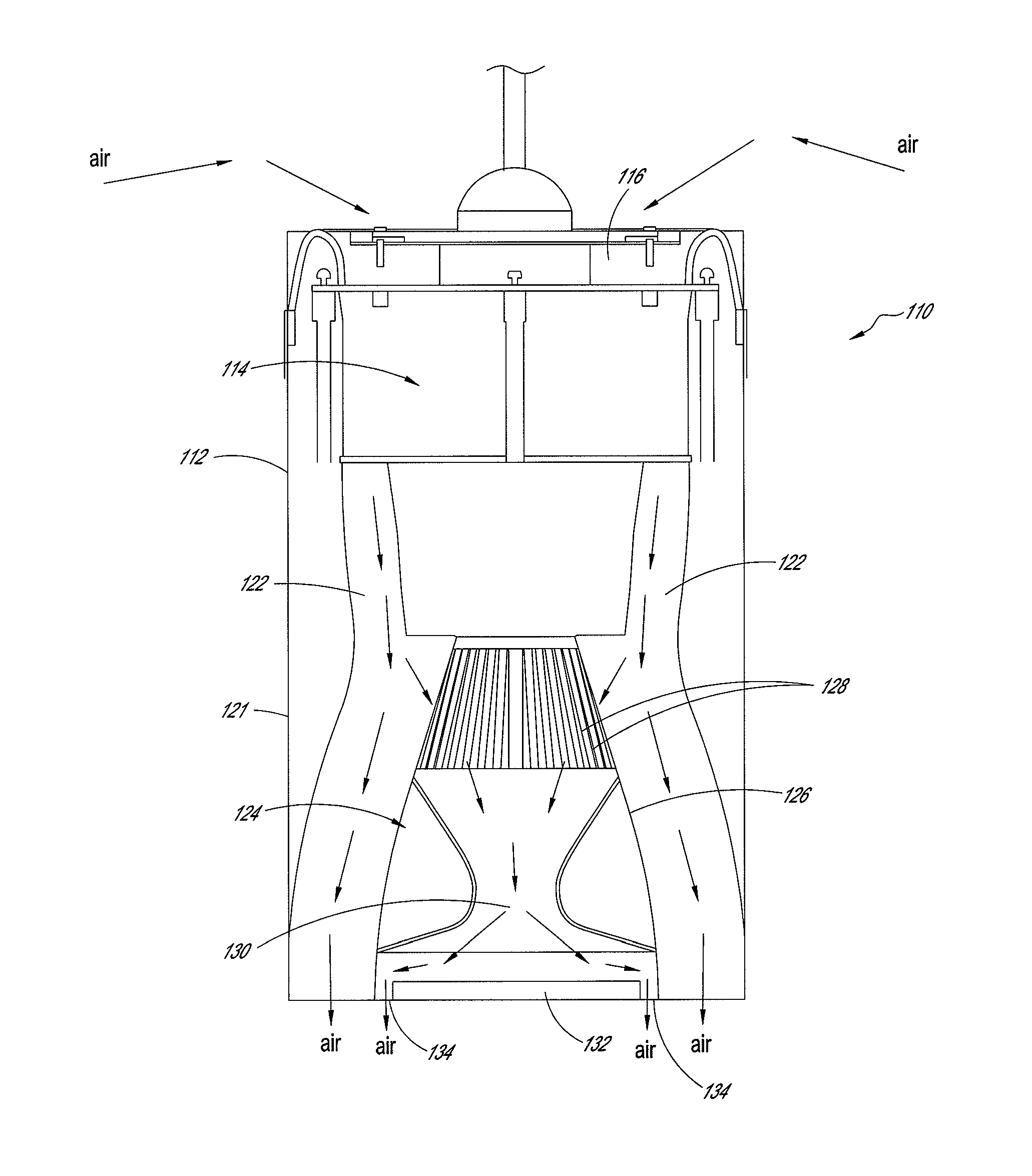
FIGS. 13-15 illustrate another embodiment of an air moving device 110, one in which the air moving device 110 includes a light source member with a specially designed ability to cool a light source. With reference to FIGS. 13-15, the air moving device 110 can include an outer housing 112. In some embodiments the outer housing 112 can comprise a generally cylindrical structure. In some embodiments the outer housing 112 can extend in an elongate manner vertically once the air moving device 110 is in an installed position.
The air moving device 110 can further comprise a rotary fan assembly 114. The rotary fan assembly 114 can be mounted within the outer housing 112. The rotary fan assembly 114 can comprise an impeller 118 and a plurality of blades 120, similar to the impeller 30 and blades 32 described above. The rotary fan assembly 114 can be configured to direct a volume of air that has entered through a top portion 116 of the air moving device 10 downwardly through a nozzle 121 of the air moving device 10. The top portion 116 can comprise a structure for air intake, for example a cowling, grill, etc., such as the structures described above for the air moving device 10. The rotary fan assembly 114 can push, or force, a volume of air downwardly within an interior space 122 of the air moving device 110. The rotary fan assembly 114 can comprise a motor. For example, the impeller 118 itself can house a motor. The motor can cause the impeller and blades to spin. In some embodiments, the motor can be located elsewhere within the air moving device 110, or located at least partially outside the air moving device 110. The rotary fan assembly 114 can comprise at least one electrical component. The rotary fan assembly can be powered via an electrical power source (e.g. via power cord extending into the top of the device).
The air moving device 110 can further comprise a light source member 124 in the nozzle 121 (e.g. at the bottom of the nozzle 121). The light source member 124 can be similar to the light source member 46 described above. The light source member 124 can comprise a housing 126. The housing 126 can include one or more openings 128. The openings 128 can be in the form of slits extending around a top portion of the housing 126. The openings 128 can permit some of the air that has exited the rotary fan assembly 114 and is traveling through the interior space 122 to enter an inside chamber 130 of the light source member 124. In some embodiments, the inside chamber 130 can have the shape of an hour-glass. For example, as illustrated in FIG. 13, the inside chamber 130 can have a narrowed profile in a middle portion of the chamber 130.
With continued reference to FIGS. 13-15, the light source member 124 can include at least one LED light engine 132, or other source of light. The light engine 132 can be similar to the lens 54 described above. In some embodiments the light engine 132 can comprise a disk-like structure. The light engine 132 can be used to direct light out of the air moving device 110. In some embodiments the light engine can be powered by the same power source that powers the rotor fan assembly 114. A power cord can be extended down through the outer housing 112 and connected to the light engine 132. In some embodiments the power cord can hold the light engine 132 in place. In some embodiments the light engine can be connected to the housing 126 of the light source member 124.
With continued reference to FIGS. 13-15, in some embodiments the air moving device 110 can comprise stator vanes 136 within the interior space 122. The stator vanes 136 can help to guide the air movement through the air moving device 110. The stator vanes 136 can be positioned equidistantly in a circumferential pattern. For example, in some embodiments, four stator vanes 136 can be used. The stator vanes 136 can be used to straighten a volume of air within air moving device 110. The stator vanes 136 can be used to force a volume of air to move in a generally columnar direction downwardly towards the floor of a building or other structure, with minimal lateral dispersion.
In some embodiments, a portion or portions of the housing 112 can be transparent, so as to allow light from the light source member 124 to escape out the sides of the device, and to illuminate areas other than areas directly below the air moving device 110.
With reference to FIG. 13, arrows are illustrated which show air movement throughout the air moving device 110. Air is first brought in through the top 116 of the air moving device 110. The air then travels through the rotary fan assembly 114, where it is directly downwardly in a columnar manner into the interior space 122. The interior space 122 can have a curved profile, as seen in FIG. 13, such that a high pressure area is created around the openings 128 of the housing 126. This high pressure area can help force at least a portion of the air into the housing 126 and chamber 130 of the light source member 124. The chamber 130 can be used to cool the light engine 132. For example, as air is moved through the narrowed (i.e. hour-glass) profile of the chamber 130, the air can enter an expanded profile near the light engine 132. The air can then move directly over the light engine 132, laterally along the light engine 132, and continue on and down along the sides of the light engine 132 and out through the openings 134. Simultaneously, the remainder of the air traveling through the interior space 122 that did not enter the light source member 124 can continue to travel through the interior space 122 and finally out of the air moving device 110, as illustrated by the arrows exiting the bottom of the air moving device in FIG. 13.
Overall, the cooling effect of the chamber 130, and the use of the chamber 130 and openings 128 in the light source member 124, can advantageously reduce the temperature of the light engine 132 so as to avoid overheating. This cooling effect can also reduce the need for additional heat sinks at or near the light engine 132, and can extend the life of a particular light engine, sometimes by thousands of hours. In some embodiments, the light engine 132 can additionally comprise one or more heat sinks. For example, the light engine 132 can comprise a rib or ribs which help to further reduce overheating of the light engine 132.
The de-stratification devices with light source members described above can advantageously be used in all types of structures, including but not limited to residential buildings, as well as large warehouses, hangers, and structures with high ceilings. In contrast, commonly used can light devices that include fans are designed primarily for use in bathrooms, showers, kitchen, and other similar areas. These devices are used for ventilation purposes, or to cool, for example, recessed lighting. These devices often require large amounts of electricity to power both the fan and the light, and are different than the de-stratification device described above.
The air moving device described above advantageously can function both as a means of de-stratification, as well as a means of providing light. Because of the combination of de-stratification and a light source member, the life of the light source member can be improved. This reduces the number of times someone will be required to access the light source member. Because of the high ceilings, accessing the light source member can often be difficult. The access often requires using a riser (e.g. a mechanical lift). This adds extra cost, and requires time that is otherwise saved with a combined de-stratification device and light source member.
In some embodiments, more than one air moving device 10, 110 can be used, in a cascading manner, to direct air flow within a structure. For example, and with reference to FIG. 16, in some embodiments a plurality of air moving devices 10, 110 can be spaced apart from one another along a ceiling structure 210 above a floor 212. The air moving devices 10, 110 can be angled, so that columns of exiting air work together to direct and de-stratify and/or move large volumes of air in one direction or another. In some embodiments, air exiting out the bottom of one air moving device 10 can enter the top of another air moving device 10. In some embodiments the ceiling structure 210 can be that of a building, room, or other structure. In some embodiments, the ceiling structure 210 can be that of a subway tunnel, or underground structure, where it may be advantageous to direct large volumes of air, in a cascading manner, so as to move and de-stratify the otherwise stagnant, hot air that often accumulates underground. In embodiments where the air moving device 10 includes a light source member 46, 124, the light source member 46, 124 can also provide additional lighting to an area below.
In some embodiments, rather than using a plurality of air moving devices 10, 110 in a ceiling structure 210, the air moving device 10, 110 can be mounted to outside structures, and the columns of air can be used to cool an outside area. For example, a plurality of air moving devices 10, 110 can be arranged in a cascading manner such that the devices 10, 110 work together to help cool people that are standing outside below the air moving devices 10, 110. Sometimes people are required to stand in long lines outdoors during hot times of the year. By arranging a plurality of air moving devices 10, 110 near the long lines, the people in line can be kept cool and comfortable, and at night can be blanketed with light if desired. In embodiments where the air moving device 10, 110 includes a light source member 46, 124 the light source member 46, 124 can also provide additional lighting to an area below.
In some embodiments, the cascading system can be operated so that the air moving devices 10, 110 do not all function at the same time. For example, in some embodiments some of the air moving devices 10, 110 can be shut off. In some embodiments the air moving devices 10, 110 can be turned on one after another, moving along a row of cascading devices 10, 110 as needed, to move the air in a large air space. In some embodiments the cascading system of air devices 10, 110 can be operated wirelessly with a wireless control system.
Although these inventions have been disclosed in the context of certain preferred embodiments and examples, it will be understood by those skilled in the art that the present inventions extend beyond the specifically disclosed embodiments to other alternative embodiments and/or uses of the inventions and obvious modifications and equivalents thereof. In addition, while several variations of the inventions have been shown and described in detail, other modifications, which are within the scope of these inventions, will be readily apparent to those of skill in the art based upon this disclosure. It is also contemplated that various combinations or sub-combinations of the specific features and aspects of the embodiments can be made and still fall within the scope of the inventions. It should be understood that various features and aspects of the disclosed embodiments can be combined with or substituted for one another in order to form varying modes of the disclosed inventions. Thus, it is intended that the scope of at least some of the present inventions herein disclosed should not be limited by the particular disclosed embodiments described above.
* * * * *
References
D00000
D00001
D00002
D00003
D00004
D00005
D00006
D00007
D00008
D00009
D00010
D00011
D00012

D00013

D00014

D00015

D00016
XML
uspto.report is an independent third-party trademark research tool that is not affiliated, endorsed, or sponsored by the United States Patent and Trademark Office (USPTO) or any other governmental organization. The information provided by uspto.report is based on publicly available data at the time of writing and is intended for informational purposes only.
While we strive to provide accurate and up-to-date information, we do not guarantee the accuracy, completeness, reliability, or suitability of the information displayed on this site. The use of this site is at your own risk. Any reliance you place on such information is therefore strictly at your own risk.
All official trademark data, including owner information, should be verified by visiting the official USPTO website at www.uspto.gov. This site is not intended to replace professional legal advice and should not be used as a substitute for consulting with a legal professional who is knowledgeable about trademark law.