Series fan inclination structure
Chang , et al. Ja
U.S. patent number 10,184,477 [Application Number 15/368,702] was granted by the patent office on 2019-01-22 for series fan inclination structure. This patent grant is currently assigned to ASIA VITAL COMPONENTS CO., LTD.. The grantee listed for this patent is ASIA VITAL COMPONENTS CO., LTD.. Invention is credited to Bor-Haw Chang, Yu-Tzu Chen, Chung-Shu Wang.


| United States Patent | 10,184,477 |
| Chang , et al. | January 22, 2019 |
Series fan inclination structure
Abstract
A series fan inclination structure includes an inclined frame body assembly, a first rotor assembly and a second rotor assembly. The inclined frame body assembly has a receiving space. The receiving space includes a first space, a second space and a flow guide passage. A first base seat is obliquely disposed in the first space. A second base seat is obliquely disposed in the second space. The flow guide passage is formed between the first and second base seats in communication with the first and second spaces. The first and second rotor assemblies are correspondingly rotatably disposed on the first and second base seats. The series fan inclination structure is able to greatly reduce the vibration and lower the noise caused by the interaction of the dipole.
| Inventors: | Chang; Bor-Haw (New Taipei, TW), Chen; Yu-Tzu (New Taipei, TW), Wang; Chung-Shu (New Taipei, TW) | ||||||||||
|---|---|---|---|---|---|---|---|---|---|---|---|
| Applicant: |
|
||||||||||
| Assignee: | ASIA VITAL COMPONENTS CO., LTD.
(New Taipei, TW) |
||||||||||
| Family ID: | 62240554 | ||||||||||
| Appl. No.: | 15/368,702 | ||||||||||
| Filed: | December 5, 2016 |
Prior Publication Data
| Document Identifier | Publication Date | |
|---|---|---|
| US 20180156222 A1 | Jun 7, 2018 | |
| Current U.S. Class: | 1/1 |
| Current CPC Class: | F04D 19/007 (20130101); F04D 29/665 (20130101); F04D 25/166 (20130101); F04D 25/08 (20130101) |
| Current International Class: | F04D 19/00 (20060101); F04D 29/66 (20060101); F04D 25/08 (20060101); F04D 25/16 (20060101) |
| Field of Search: | ;361/676-678,679.46-679.54,688-723,699-704,709-710,719-721 ;165/80.1-80.5,104.33,185 ;174/15.1-15.3,16.1-16.3,547,548 ;257/712-722,E23.088 ;24/453,458-459 ;454/184 ;312/236 |
References Cited [Referenced By]
U.S. Patent Documents
| 5244347 | September 1993 | Gallivan |
| 5544012 | August 1996 | Koike |
| 5796580 | August 1998 | Komatsu |
| 5880932 | March 1999 | Jelinger |
| 6061237 | May 2000 | Sands |
| 6183214 | February 2001 | Ko |
| 6315656 | November 2001 | Pawlowski |
| 6481527 | November 2002 | French |
| 6512673 | January 2003 | Wiley |
| 6537019 | March 2003 | Dent |
| 7238104 | July 2007 | Greenslade |
| 7626819 | December 2009 | Chen |
| 7771165 | August 2010 | Chen |
| 7824155 | November 2010 | Chen |
| 7990700 | August 2011 | Guo |
| 8047803 | November 2011 | Yamada |
| 8100674 | January 2012 | Lin |
| 8177486 | May 2012 | Lee |
| 8757970 | June 2014 | Hsu |
| 8817470 | August 2014 | Aoki |
| 2002/0018337 | February 2002 | Nakamura |
| 2002/0075647 | June 2002 | DiFonzo |
| 2002/0153371 | October 2002 | Oshima |
| 2003/0198018 | October 2003 | Cipolla |
| 2005/0052843 | March 2005 | Baker |
| 2005/0260065 | November 2005 | Kikuichi |
| 2006/0039110 | February 2006 | Foster, Sr. |
| 2006/0268514 | November 2006 | Fan |
| 2007/0047200 | March 2007 | Huang |
| 2007/0109743 | May 2007 | Sugimoto |
| 2007/0158053 | July 2007 | Nicolai |
| 2008/0053639 | March 2008 | Lin |
| 2008/0101021 | May 2008 | Sanchez |
| 2008/0218446 | September 2008 | Yamanaka |
| 2008/0314555 | December 2008 | Wu |
| 2009/0022587 | January 2009 | Yoshida |
| 2009/0139691 | June 2009 | Wei |
| 2009/0230201 | September 2009 | Na |
| 2010/0027215 | February 2010 | Wu |
| 2010/0073873 | March 2010 | Horng |
| 2010/0107397 | May 2010 | Letourneau |
| 2010/0149753 | June 2010 | Lin |
| 2010/0296237 | November 2010 | Guo |
| 2011/0149513 | June 2011 | Silvennoinen |
| 2011/0255245 | October 2011 | Cheng |
| 2011/0292604 | December 2011 | Janes |
| 2012/0009059 | January 2012 | Okamoto |
| 2012/0026678 | February 2012 | Rodriguez |
| 2012/0045325 | February 2012 | Horng |
| 2012/0057973 | March 2012 | Chen |
| 2012/0113593 | May 2012 | Hsu |
| 2012/0171057 | July 2012 | Wu |
| 2012/0183396 | July 2012 | Feng |
| 2012/0201003 | August 2012 | Shimasaki |
| 2013/0070409 | March 2013 | Hoss |
| 2013/0070417 | March 2013 | Du |
| 2013/0168064 | July 2013 | Akiyoshi |
| 2013/0229774 | September 2013 | Chen |
| 2014/0118926 | May 2014 | Santos |
| 2014/0118937 | May 2014 | Adrian |
| 2014/0233185 | August 2014 | Wen |
| 2015/0086351 | March 2015 | Chang |
| 2015/0354598 | December 2015 | Dygert |
| 2016/0381836 | December 2016 | Hall |
| 2018/0028407 | February 2018 | Omura |
| 2018/0135650 | May 2018 | Chang |
Assistant Examiner: Gafur; Razmeen
Attorney, Agent or Firm: Jackson IPG PLLC Jackson; Demian K.
Claims
What is claimed is:
1. A non-coaxial series fan structure comprising: an inclined fan frame body assembly having a receiving space including: a first rotor space, a second rotor space, a flow guide passage, a first base seat obliquely disposed in the first rotor space and having multiple first support sections, and a second base seat obliquely disposed in the second rotor space and having multiple second support sections, the first and second support sections being connected to an inner wall of the inclined fan frame body assembly and the first and the second support sections each configured as static inclined blade structures, the flow guide passage being formed between the first and second base seats in communication with the first and second rotor spaces; a first rotor assembly disposed on the first base seat; and a second rotor assembly disposed on the second base seat, wherein the first and second rotor assemblies are disposed in a non-coaxial, series arrangement such that the first rotor assembly drives an airflow to pass through the second rotor assembly, a flow direction and pattern of the airflow entering the non-coaxial series fan structure changing therein so as to destroy development of an audio frequency dipole.
2. The non-coaxial series fan structure as claimed in claim 1, wherein the inclined fan frame body assembly has a horizontal axis, the horizontal axis and outer wall of the inclined frame body assembly containing a first angle.
3. The non-coaxial series fan structure as claimed in claim 1, wherein the inclined fan frame body assembly has a first vertical axis, the first vertical axis and the first base seat containing a second angle.
4. The non-coaxial series fan structure as claimed in claim 1, wherein the inclined fan frame body assembly has a second vertical axis, the second vertical axis and the second base seat containing a third angle.
5. The non-coaxial series fan structure as claimed in claim 1, wherein the inclined fan frame body assembly further has a first support frame and a second support frame, the first support frame and the first base seat being integrally formed, the second support frame and the second base seat being integrally formed.
6. The non-coaxial series fan structure as claimed in claim 5, wherein the first and second support frames are assembled by insertion, locking, adhesion, engagement or latching.
7. The non-coaxial series fan structure as claimed in claim 5, wherein the first support frame has a first air inlet and a first air outlet, the first air inlet and the first air outlet communicating with the first space, the second support frame having a second air inlet and a second air outlet, the second air inlet and the second air outlet communicating with the second space.
8. The non-coaxial series fan structure as claimed in claim 1, wherein the inclined fan frame body assembly has an upper support frame and a lower support frame, the lower support frame and the first and second base seats integrally formed.
9. The non-coaxial series fan structure as claimed in claim 8, wherein the upper and lower support frames are assembled by insertion, locking, adhesion, engagement or latching.
10. The non-coaxial series fan structure as claimed in claim 1, wherein the first rotor assembly has a first receiving section for receiving therein a first stator assembly and the second rotor assembly has a second receiving section for receiving therein a second stator assembly.
Description
BACKGROUND OF THE INVENTION
1. Field of the Invention
The present invention relates generally to a series fan inclination structure, and more particularly to a series fan inclination structure, which can greatly reduce the vibration and lower the noise.
2. Description of the Related Art
Along with the continuous advance of science and technologies, the dependence of peoples on various electronic apparatuses has more and more increased. In operation, the internal components of the electronic products (such as computers and notebooks) will generate high heat. The heat generated by the internal components must be conducted outside the electronic product in time. Otherwise, the electronic product will overheat. In general, a fan is disposed in the electronic product to dissipate the heat and keep the electronic product operating at an operation temperature within a certain range.
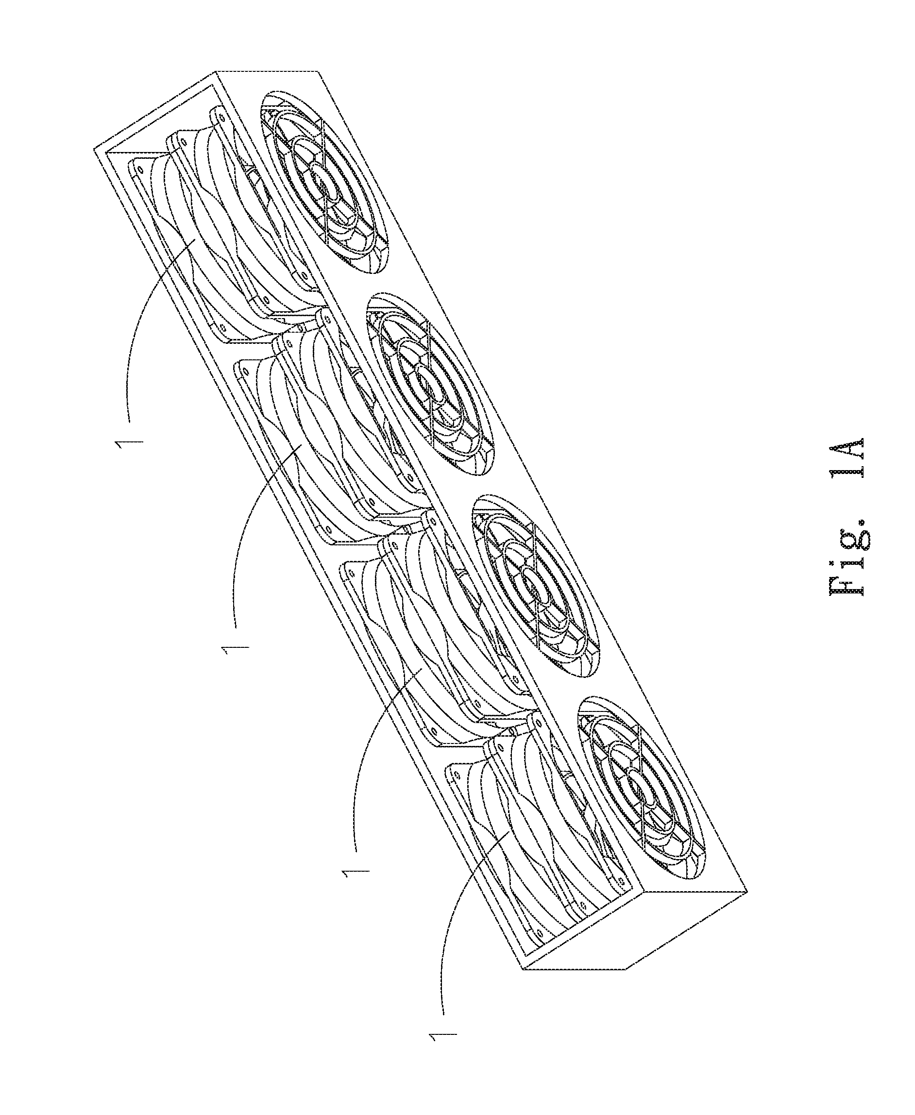
Please refer to FIGS. 1A and 1B. In a conventional series fan 1, the fan frames 10 are mated and serially connected with each other. With respect to the heat dissipation of a large-scale apparatus, sometimes multiple series fans are further combined in parallel and co-used. When the series fan 1 operates, on the design principle of the motor torque operation, the fan 1 will inevitably vibrate, especially in the case that more than two series fans 1 are combined in parallel and co-used. The parallel combination of the series fans 1 is able to increase the air volume so as to effectively exhaust the heat from the interior of the electronic product. However, when all the series fans 1 simultaneously operate, under the inter-affection of the ground-state vibration frequency of the fan impellers 11 of the fans 1, the fan frames 10 will severely resonate. The series fans 1 are combined in parallel so that the pairs of fans will interact on each other to synergize the development of the noise dipole. This will make loud noise.
According to the above, the conventional series fan has the following shortcomings:
1. The vibration of the fan is more serious.
2. Due to the development and interaction of the dipole, the fan will make loud noise.
It is therefore tried by the applicant to provide a series fan inclination structure to solve the above problems of the conventional series fan.
SUMMARY OF THE INVENTION
It is therefore a primary object of the present invention to provide a series fan inclination structure, which can greatly reduce the vibration.
It is a further object of the present invention to provide a series fan inclination structure, which can destruct the interaction of the noise dipole so as to lower the noise.
To achieve the above and other objects, the series fan inclination structure of the present invention includes an inclined frame body assembly, a first rotor assembly and a second rotor assembly. The inclined frame body assembly has a receiving space. The receiving space includes a first space, a second space and a flow guide passage. A first base seat is obliquely disposed in the first space. A second base seat is obliquely disposed in the second space. The flow guide passage is formed between the first and second base seats in communication with the first and second spaces. The first rotor assembly is correspondingly disposed on the first base seat. The first rotor assembly has a first shaft and multiple first blades. One end of the first shaft is rotatably disposed on the first base seat. The second rotor assembly is correspondingly disposed on the second base seat. The second rotor assembly has a second shaft and multiple second blades. One end of the second shaft is rotatably disposed on the second base seat.
In the above series fan inclination structure, the inclined frame body assembly has a horizontal axis. The horizontal axis and outer wall of the inclined frame body assembly contain a first angle. The inclined frame body assembly has a first vertical axis. The first vertical axis and the first base seat contain a second angle. The inclined frame body assembly has a second vertical axis. The second vertical axis and the second base seat contain a third angle. In other words, the inclined frame body assembly has an inclined configuration and the first and second base seats are obliquely disposed on the inner wall of the inclined frame body assembly. Therefore, the first and second rotor assemblies are also rotatably disposed on the first and second base seats in an inclined state. Accordingly, the entire series fan has an inclined structure. In this case, the flow direction and pattern of the airflow entering the series fan structure are changed and the development of audio frequency of the dipole is destructed. This solves the problem of the conventional series fan that when multiple series fans are combined in parallel and co-used, the pairs of fans will interact on each other to synergize the development of the noise dipole and cause great vibration and make loud noise. Therefore, the present invention can greatly lower the noise.
BRIEF DESCRIPTION OF THE DRAWINGS
The structure and the technical means adopted by the present invention to achieve the above and other objects can be best understood by referring to the following detailed description of the preferred embodiments and the accompanying drawings, wherein:
FIG. 1A is a perspective view of a conventional series fan structure;
FIG. 1B is a sectional assembled view of the conventional series fan structure;
FIG. 2 is a perspective exploded view of a first embodiment of the series fan inclination structure of the present invention;
FIG. 3 is a perspective assembled view of the first embodiment of the series fan inclination structure of the present invention;
FIG. 4 is a sectional view of the first embodiment of the series fan inclination structure of the present invention;
FIG. 5 is a sectional view of a second embodiment of the series fan inclination structure of the present invention;
FIG. 6 is a perspective exploded view of a third embodiment of the series fan inclination structure of the present invention;
FIG. 7 is a perspective assembled view of the third embodiment of the series fan inclination structure of the present invention;
FIG. 8 is a perspective assembled view of a fourth embodiment of the series fan inclination structure of the present invention; and
FIG. 9 is a sectional assembled view of the fourth embodiment of the series fan inclination structure of the present invention.
DETAILED DESCRIPTION OF THE PREFERRED EMBODIMENTS
Please refer to FIGS. 2, 3 and 4. FIG. 2 is a perspective exploded view of a first embodiment of the series fan inclination structure of the present invention. FIG. 3 is a perspective assembled view of the first embodiment of the series fan inclination structure of the present invention. FIG. 4 is a sectional view of the first embodiment of the series fan inclination structure of the present invention. According to the first embodiment, the series fan inclination structure 2 of the present invention includes an inclined frame body assembly 21, a first rotor assembly 23 and a second rotor assembly 24. The inclined frame body assembly 21 has a receiving space 22. The receiving space 22 includes a first space 221, a second space 222 and a flow guide passage 223. A first base seat 224 is obliquely disposed in the first space 221. A second base seat 225 is obliquely disposed in the second space 222. The flow guide passage 223 is formed between the first and second base seats 224, 225 in communication with the first and second spaces 221, 222. The first base seat 224 has multiple first support sections 2241. The second base seat 225 has multiple second support sections 2251. The first and second support sections 2241, 2251 are connected to the inner wall of the inclined frame body assembly 21. The structure and configuration of the first and second support sections 2241, 2251 can be designed as static blade wing-shaped structures (as shown in FIG. 2) or rib structures (not shown) according to the requirement of a user. This will not affect the effect achieved by the present invention.
The inclined frame body assembly 21 has a horizontal axis L1. The horizontal axis L1 and the outer wall of the inclined frame body assembly 21 contain a first angle .alpha.. The inclined frame body assembly 21 has a first vertical axis L2. The first vertical axis L2 and the first base seat 224 contain a second angle .beta.. The inclined frame body assembly 21 further has a second vertical axis L3. The second vertical axis L3 and the second base seat 225 contain a third angle .gamma.. The first, second and third angles .alpha., .beta., .gamma. are not specifically limited and are determined by the inclination of the inclined frame body assembly 21 and the inclinations of the first and second base seats 224, 225 obliquely disposed in the first and second spaces 221, 222.
The first rotor assembly 23 is correspondingly disposed on the first base seat 224. The first rotor assembly 23 has a first shaft 232 and multiple first blades 233. One end of the first shaft 232 is rotatably disposed on the first base seat 224. The first rotor assembly 23 further has a first receiving section 231 for receiving therein a first stator assembly 25.
The second rotor assembly 24 is correspondingly disposed on the second base seat 225. The second rotor assembly 24 has a second shaft 242 and multiple second blades 243. One end of the second shaft 242 is rotatably disposed on the second base seat 225. The second rotor assembly 24 further has a second receiving section 241 for receiving therein a second stator assembly 26.
Please further refer to FIGS. 2 and 3. In this embodiment, the inclined frame body assembly 21 further has a first support frame 226 and a second support frame 227. The first support frame 226 and the first base seat 224 are integrally formed. The second support frame 227 and the second base seat 225 are integrally formed. The first and second support frames 226, 227 are assembled by means of insertion, locking, adhesion, engagement or latching. The first support frame 226 has a first air inlet 2261 and a first air outlet 2262. The first air inlet 2261 and the first air outlet 2262 communicate with the first space 221. The second support frame 227 has a second air inlet 2271 and a second air outlet 2272. The second air inlet 2271 and the second air outlet 2272 communicate with the second space 222.
According to the structural design of the present invention, in use, the first air outlet 2262 of the first support frame 226 is correspondingly mated and connected with the second air inlet 2271 of the second support frame 227. (Alternatively, as shown in FIG. 5, in a second embodiment, the first air outlet 2262 of the first support frame 226 is correspondingly mated and connected with the second air outlet 2272 of the second support frame 227). The inclined frame body assembly 21 has an inclined configuration and the first and second base seats 224, 225 are obliquely disposed on the inner wall of the inclined frame body assembly 21, (that is, the first and second base seats 224, 225 and the first and second vertical axes L2, L3 contain the second and third angles .beta. and .gamma. as shown in FIGS. 4 and 5). Therefore, the first and second rotor assemblies 23, 24 are also disposed on the first and second base seats 224, 225 in a state inclined from the horizontal axis L1. Accordingly, the entire series fan has an inclined structure. In this case, after the airflow 3 flows into the first space 221 from the first air inlet 2261, the airflow 3 will flow through the flow guide passage 223 and the first air outlet 2262 and then flow into the second air inlet 2271 and the second space 222. Finally, the airflow 3 flows out from the second air outlet 2272. Accordingly, the flow direction and pattern of the airflow 3 entering the series fan structure are changed and the development of audio frequency of the dipole is destructed. This solves the problem of the conventional series fan that when multiple series fans are combined in parallel and co-used, the pairs of fans will interact on each other to synergize the development of the noise dipole and cause great vibration and make loud noise. Therefore, the present invention can be greatly lower the noise.
Please now refer to FIGS. 6 and 7. FIG. 6 is a perspective exploded view of a third embodiment of the series fan inclination structure of the present invention. FIG. 7 is a perspective assembled view of the third embodiment of the series fan inclination structure of the present invention. The third embodiment is partially identical to the first embodiment in component and relationship between the components and thus will not be repeatedly described hereinafter. The third embodiment is mainly different from the first embodiment in that in this embodiment, the inclined frame body assembly 21 has another form. The inclined frame body assembly 21 has an upper support frame 228 and a lower support frame 229. In this embodiment, the lower support frame 229 and the first and second base seats 224, 225 are, but not limited to, integrally formed. In practice, alternatively, the upper support frame 228 and the first and second base seats 224, 225 are integrally formed (not shown). The upper and lower support frames 228, 229 are assembled by means of insertion, locking, adhesion, engagement or latching. The structural design of this embodiment can also achieve the same effect as the above embodiment.
Finally, please refer to FIGS. 8 and 9. FIG. 8 is a perspective assembled view of a fourth embodiment of the series fan inclination structure of the present invention. FIG. 9 is a sectional assembled view of the fourth embodiment of the series fan inclination structure of the present invention. The fourth embodiment is partially identical to the first embodiment in component and relationship between the components and thus will not be repeatedly described hereinafter. The fourth embodiment is mainly different from the first embodiment in that multiple inclined frame body assemblies 21 are further combined in parallel and co-used. The inclined frame body assemblies 21 are applicable to a large-scale apparatus for dissipating the heat thereof. This solves the problem of the conventional series fan that when multiple series fans are combined in parallel and co-used, the pairs of fans will interact on each other to synergize the development of the noise dipole and cause great vibration and make loud noise. Therefore, the present invention can greatly lower the noise.
The present invention has been described with the above embodiments thereof and it is understood that many changes and modifications in such as the form or layout pattern or practicing step of the above embodiments can be carried out without departing from the scope and the spirit of the invention that is intended to be limited only by the appended claims.
* * * * *
D00000
D00001
D00002
D00003
D00004
D00005
D00006
D00007
D00008
D00009
D00010
XML
uspto.report is an independent third-party trademark research tool that is not affiliated, endorsed, or sponsored by the United States Patent and Trademark Office (USPTO) or any other governmental organization. The information provided by uspto.report is based on publicly available data at the time of writing and is intended for informational purposes only.
While we strive to provide accurate and up-to-date information, we do not guarantee the accuracy, completeness, reliability, or suitability of the information displayed on this site. The use of this site is at your own risk. Any reliance you place on such information is therefore strictly at your own risk.
All official trademark data, including owner information, should be verified by visiting the official USPTO website at www.uspto.gov. This site is not intended to replace professional legal advice and should not be used as a substitute for consulting with a legal professional who is knowledgeable about trademark law.