Occlusion resistant catheter and method of use
Mohan , et al. Ja
U.S. patent number 10,183,143 [Application Number 14/216,530] was granted by the patent office on 2019-01-22 for occlusion resistant catheter and method of use. This patent grant is currently assigned to Bitol Designs, LLC. The grantee listed for this patent is Bitol Designs, LLC. Invention is credited to Mark J. Bernhard, Ashik A. Mohan, Avinash L. Mohan.


View All Diagrams
| United States Patent | 10,183,143 |
| Mohan , et al. | January 22, 2019 |
Occlusion resistant catheter and method of use
Abstract
An implantable occlusion and tissue ingrowth resistant fluid interface is provided with a housing, an orifice and a catheter port. The housing is formed from at least one biocompatible material and is configured without sharp edges or corners. The housing at least partially defines an internal housing cavity. The orifice member at least partially defines an orifice between the internal housing cavity and an exterior of the housing. The orifice has an elongated transverse cross-section configured with a length that is at least four times its maximum width. The catheter port is located on the housing and is configured to couple with a catheter such that the internal housing cavity is in fluid communication with a lumen of the catheter when the catheter is coupled to the catheter port. Embodiments having a moving cylinder, a rotor, and non-chemical surface modifications, as well as methods of use are also disclosed.
| Inventors: | Mohan; Ashik A. (Alamo, CA), Mohan; Avinash L. (Yorktown Heights, NY), Bernhard; Mark J. (Alamo, CA) | ||||||||||
|---|---|---|---|---|---|---|---|---|---|---|---|
| Applicant: |
|
||||||||||
| Assignee: | Bitol Designs, LLC (Alamo,
CA) |
||||||||||
| Family ID: | 51538555 | ||||||||||
| Appl. No.: | 14/216,530 | ||||||||||
| Filed: | March 17, 2014 |
Prior Publication Data
| Document Identifier | Publication Date | |
|---|---|---|
| US 20140288479 A1 | Sep 25, 2014 | |
Related U.S. Patent Documents
| Application Number | Filing Date | Patent Number | Issue Date | ||
|---|---|---|---|---|---|
| 61801232 | Mar 15, 2013 | ||||
| Current U.S. Class: | 1/1 |
| Current CPC Class: | A61M 25/0017 (20130101); A61M 27/006 (20130101); A61M 2025/0073 (20130101) |
| Current International Class: | A61M 25/00 (20060101); A61M 27/00 (20060101) |
References Cited [Referenced By]
U.S. Patent Documents
| 3419010 | December 1968 | Donald |
| 3796950 | March 1974 | Kuecken |
| 3985140 | October 1976 | Harris |
| 3999553 | December 1976 | Spitz et al. |
| D24319 | January 1977 | Pemberton |
| D24722 | February 1978 | Pemberton |
| D25018 | November 1978 | Pemberton |
| 4205252 | May 1980 | Sinclair et al. |
| 4260983 | April 1981 | Falck et al. |
| 4261367 | April 1981 | Freese |
| 4271840 | June 1981 | Lattin et al. |
| 4327251 | April 1982 | Fomenko et al. |
| 4332255 | June 1982 | Hakim et al. |
| 4375816 | March 1983 | Labianca |
| 4399437 | August 1983 | Falck et al. |
| 4511887 | April 1985 | Fiore |
| 4540400 | September 1985 | Hooven |
| 4557721 | December 1985 | Hooven |
| 4576589 | March 1986 | Kraus et al. |
| 4578057 | March 1986 | Sussman |
| 4583967 | April 1986 | Harris |
| 4588085 | May 1986 | Sussman |
| 4598579 | July 1986 | Cummings et al. |
| 4601724 | July 1986 | Hooven et al. |
| 4605395 | August 1986 | Rose et al. |
| 4627832 | December 1986 | Hooven et al. |
| 4631051 | December 1986 | Harris |
| 4675003 | June 1987 | Hooven |
| 4676772 | June 1987 | Hooven |
| 4681559 | July 1987 | Hooven |
| 4705499 | November 1987 | Hooven |
| 4714458 | December 1987 | Hooven |
| 4714459 | December 1987 | Hooven |
| 4729762 | March 1988 | Doumenis |
| 4767400 | August 1988 | Miller et al. |
| 4769002 | September 1988 | Hooven |
| 4769016 | September 1988 | Labianca |
| 4776838 | October 1988 | Sainte Rose et al. |
| 4776839 | October 1988 | Doumenis |
| 4781672 | November 1988 | Hooven |
| 4950232 | August 1990 | Ruzicka et al. |
| 5069663 | December 1991 | Sussman |
| 5230623 | July 1993 | Guthrie et al. |
| 5336166 | August 1994 | Sierra |
| 5368556 | November 1994 | Lecuyer |
| 5409462 | April 1995 | Ross |
| 5513238 | April 1996 | Leber et al. |
| 5560358 | October 1996 | Arnold et al. |
| 5660200 | August 1997 | Paes |
| 5695514 | December 1997 | Chin |
| 5738666 | April 1998 | Watson et al. |
| 5755758 | May 1998 | Woloszko et al. |
| 5766195 | June 1998 | Nobles |
| 5782741 | July 1998 | Bradshaw et al. |
| 5797878 | August 1998 | Bleam |
| 5800376 | September 1998 | Watson et al. |
| 5843013 | December 1998 | Lecuyer et al. |
| 5865748 | February 1999 | Co et al. |
| 5911685 | June 1999 | Siess et al. |
| 5921979 | July 1999 | Kovac et al. |
| 5921992 | July 1999 | Costales et al. |
| 5928182 | July 1999 | Kraus et al. |
| 5935084 | August 1999 | Southworth |
| 5971997 | October 1999 | Guthrie et al. |
| 5983141 | November 1999 | Sluijter et al. |
| 6041101 | March 2000 | Kooy et al. |
| 6048306 | April 2000 | Spielberg |
| 6050969 | April 2000 | Kraus |
| 6110155 | August 2000 | Baudino |
| 6113613 | September 2000 | Spaulding |
| 6120465 | September 2000 | Guthrie et al. |
| 6122541 | September 2000 | Cosman et al. |
| 6146380 | November 2000 | Racz et al. |
| 6161048 | December 2000 | Sluijter et al. |
| 6167295 | December 2000 | Cosman |
| 6193682 | February 2001 | Ahmed |
| 6275725 | August 2001 | Cosman |
| 6348042 | February 2002 | Warren |
| 6371464 | April 2002 | Porche et al. |
| 6383159 | May 2002 | Saul et al. |
| 6402771 | June 2002 | Palmer et al. |
| 6415823 | July 2002 | Vasek et al. |
| 6436142 | August 2002 | Pees et al. |
| 6506199 | January 2003 | Rogers et al. |
| 6540727 | April 2003 | Harper et al. |
| 6540736 | April 2003 | Harper et al. |
| 6689085 | February 2004 | Rubenstein et al. |
| 6692493 | February 2004 | McGovern et al. |
| 6731976 | May 2004 | Penn et al. |
| 6852122 | February 2005 | Rush |
| 6871740 | March 2005 | Cao |
| 6881210 | April 2005 | Wilson |
| 6883241 | April 2005 | Moskowitz et al. |
| 6913589 | July 2005 | Dextradeur et al. |
| 6916310 | July 2005 | Sommerich |
| 6919100 | July 2005 | Narayanan |
| 6953444 | October 2005 | Rosenberg |
| 7025739 | April 2006 | Saul |
| 7036369 | May 2006 | Keppner et al. |
| 7037288 | May 2006 | Rosenberg et al. |
| 7059330 | June 2006 | Makower et al. |
| 7069779 | July 2006 | Zumkehr et al. |
| 7094214 | August 2006 | Dextradeur et al. |
| 7172571 | February 2007 | Moskowitz et al. |
| 7181963 | February 2007 | Bork |
| 7189221 | March 2007 | Silverberg et al. |
| 7192413 | March 2007 | Kraus et al. |
| 7195640 | March 2007 | Falotico et al. |
| 7226441 | June 2007 | Kulessa |
| 7235060 | June 2007 | Kraus |
| 7261735 | August 2007 | Llanos et al. |
| D550348 | September 2007 | Copley et al. |
| 7286879 | October 2007 | Wallace |
| 7300434 | November 2007 | Moskowitz et al. |
| 7303758 | December 2007 | Falotico et al. |
| 7304277 | December 2007 | Weber |
| 7309330 | December 2007 | Bertrand et al. |
| 7320676 | January 2008 | Miesel |
| 7334582 | February 2008 | Bertrand et al. |
| 7334594 | February 2008 | Ludin |
| 7415309 | August 2008 | McIntyre |
| 7510533 | March 2009 | Mauge et al. |
| 7530963 | May 2009 | Albright |
| 7582068 | September 2009 | Koullick et al. |
| 7585280 | September 2009 | Wilson et al. |
| 7614743 | November 2009 | Geiger |
| 7620456 | November 2009 | Gliner et al. |
| 7695731 | April 2010 | Falotico et al. |
| 7715896 | May 2010 | Ramzipoor et al. |
| 7736312 | June 2010 | Taylor et al. |
| 7771381 | August 2010 | McCusker et al. |
| 7806924 | October 2010 | Falotico et al. |
| 7812290 | October 2010 | Weber |
| 7842004 | November 2010 | Kassem |
| 7846940 | December 2010 | Falotico et al. |
| 7875282 | January 2011 | Falotico et al. |
| 7922685 | April 2011 | Rosenberg |
| 8015977 | September 2011 | Bertrand et al. |
| 8088092 | January 2012 | McCusker et al. |
| 8192445 | June 2012 | Parmer et al. |
| 8216296 | July 2012 | Wu et al. |
| 8389083 | March 2013 | Atanasoska et al. |
| 8622978 | January 2014 | Bertrand et al. |
| 2003/0004495 | January 2003 | Saul |
| 2004/0068201 | April 2004 | Saul |
| 2004/0092908 | May 2004 | Harper et al. |
| 2005/0043669 | February 2005 | Rosenberg |
| 2005/0043670 | February 2005 | Rosenberg |
| 2005/0055009 | March 2005 | Rosenberg |
| 2005/0137579 | June 2005 | Heruth |
| 2005/0256510 | November 2005 | Moskowitz et al. |
| 2006/0079927 | April 2006 | Kaemmerer et al. |
| 2006/0211944 | September 2006 | Mauge et al. |
| 2006/0211945 | September 2006 | Mauge et al. |
| 2006/0222756 | October 2006 | Lentz et al. |
| 2006/0224102 | October 2006 | Glenn |
| 2007/0004999 | January 2007 | Miethke |
| 2007/0197952 | August 2007 | Stiger |
| 2007/0203516 | August 2007 | Nayak |
| 2008/0039768 | February 2008 | Francis |
| 2008/0039770 | February 2008 | Francis et al. |
| 2008/0082036 | April 2008 | Trescony et al. |
| 2008/0140051 | June 2008 | Bei et al. |
| 2008/0249458 | October 2008 | Yamasaki |
| 2009/0105725 | April 2009 | O'Connor et al. |
| 2010/0249691 | September 2010 | Van Der Mooren et al. |
| 2010/0303722 | December 2010 | Jin |
| 2012/0232462 | September 2012 | Miethke |
| 1056088 | Sep 2000 | CN | |||
| WO02/20083 | Mar 2002 | WO | |||
Assistant Examiner: Weng; Kai
Attorney, Agent or Firm: Shay Glenn LLP
Parent Case Text
CROSS-REFERENCE TO RELATED APPLICATIONS
This application claims the benefit under 35 U.S.C. 119 of U.S. Provisional Patent Application 61/801,232 filed Mar. 15, 2013, and entitled "Occlusion Resistant Catheter and Method of Use."
Claims
What is claimed is:
1. An implantable occlusion resistant fluid interface comprising: an outer housing formed from at least one biocompatible material and configured without sharp external edges or corners, the outer housing at least partially defining an internal housing cavity; an orifice member formed from at least one biocompatible material and coupled with the outer housing in a manner that permits the orifice member to be freely movable in at least one of a lateral direction and a longitudinal direction with respect to the outer housing and to float between a first side and an opposite side of the outer housing, the movable orifice member together with the first side of the outer housing at least partially defining edges of a first orifice, the first orifice providing fluid communication between the internal housing cavity and an exterior of the outer housing, the first orifice having a first elongated cross-section configured to be transverse to a fluid flow between the internal housing cavity and the exterior of the outer housing, the first elongated cross-section having a maximum width and configured with a length that is at least four times the maximum width, wherein the maximum width of the first elongated cross-section varies when the orifice member floats or moves with respect to the outer housing, wherein the first orifice is configured to be in direct fluid contact with a region of a patient without an intervening restriction located between the first orifice and the region of the patient, the movable orifice member together with the opposite side of the outer housing at least partially defining edges of a second orifice, the second orifice providing fluid communication between the internal housing cavity and the exterior of the outer housing, the second orifice having a second elongated cross-section configured to be transverse to a second fluid flow between the internal housing cavity and the exterior of the outer housing, the second elongated cross-section having a second maximum width and configured with a second length that is at least four times the second maximum width, wherein the maximum width of the second elongated cross-section varies when the orifice member floats or moves with respect to the outer housing, wherein the second orifice is configured to be in direct fluid contact with a second region of the patient without an intervening restriction located between the second orifice and the second region of the patient; and a catheter port located on the outer housing and configured to couple with a catheter such that the internal housing cavity is in fluid communication with a lumen of the catheter when coupled to the catheter port.
2. The fluid interface of claim 1, wherein the maximum width of the transverse cross-section of the first orifice does not exceed 0.003 inches.
3. The fluid interface of claim 1, wherein the orifice member is freely movable in both the lateral direction and the longitudinal direction with respect to the outer housing.
4. The fluid interface of claim 3, wherein the movable orifice member comprises a plate.
5. The fluid interface of claim 1, wherein the housing is formed from at least two separate pieces that are joined together to captivate the orifice member therebetween.
6. The fluid interface of claim 5, wherein each of the at least two separate pieces is an elongated hemispherical toroidal shell that form a completed elongated toroidal shell when joined together, and wherein the orifice member is located across a central aperture of the toroid.
7. The fluid interface of claim 1, wherein the first and the second elongated cross-sections have a combined width that remains constant as the orifice member floats between the first side and the opposite side of the outer housing such that fluid flow through the fluid interface is not restricted as the orifice member floats.
8. The fluid interface of claim 7, wherein the first and the second elongated cross-sections have a combined width that remains constant as the orifice member freely moves in at least one of a lateral direction and a longitudinal direction with respect to the outer housing such that fluid flow through the fluid interface is not restricted as the orifice member freely moves.
9. The fluid interface of claim 1, wherein the orifice member movably resides in an oval shaped aperture through the outer housing.
10. An implantable occlusion resistant fluid interface comprising: a housing formed from at least one biocompatible material and configured without sharp external edges or corners, the housing at least partially defining an internal housing cavity; an orifice member formed from at least one biocompatible material and at least partially defining an orifice between the internal housing cavity and an exterior of the housing, the orifice having an elongated transverse cross-section configured to be transverse to a fluid flow between the internal housing cavity and the exterior of the housing, the elongated cross-section having a maximum width and configured with a length that is at least four times the maximum width, wherein the orifice is configured to be in direct fluid contact with a region of a patient without an intervening restriction located between the orifice and the region of the patient; and a catheter port located on the housing and configured to couple with a catheter such that the internal housing cavity is in fluid communication with a lumen of the catheter when coupled to the catheter port, wherein the orifice member comprises nano-ripples formed by ion blasting on one or more surfaces, the nano-ripples having a height of 50 nm or less and a spacing of 52 nm or less.
11. An implantable occlusion resistant shunt comprising: the fluid interface of claim 1; and a flexible catheter formed from a biocompatible material and having a first end and a second end, wherein the first end is coupled with the catheter port of the fluid interface.
12. The shunt of claim 11, further comprising a second fluid interface according to claim 1, wherein the second end of the catheter is coupled with the catheter port of the second fluid interface.
13. A method of treating hydrocephalus comprising: providing the shunt of claim 11; implanting the fluid interface and the first end of the catheter within a patient adjacent to brain tissue; implanting a remainder of the catheter within the patient; and locating the second end of the catheter in a region of the patient away from the brain tissue.
Description
INCORPORATION BY REFERENCE
All publications and patent applications mentioned in this specification are herein incorporated by reference in their entirety to the same extent as if each individual publication or patent application was specifically and individually indicated to be incorporated by reference.
FIELD
The present disclosure relates to implantable occlusion resistant fluid interfaces, such as catheter tips used in the treatment of hydrocephalus.
BACKGROUND
One application of the occlusion resistant catheters disclosed herein is in shunting systems for cerebral-spinal fluid for use in treating hydrocephalus. Conventional shunting systems used for this purpose typically include three components: a ventricular catheter portion; a peritoneal catheter portion; and a valve located between the two catheter portions. The catheter portions typically are formed from a flexible synthetic polymer such as silicone rubber. A proximal end of the ventricular catheter portion is configured for insertion in a cerebral ventricle. A distal end of the peritoneal catheter portion is configured for insertion in a body cavity, or in some cases configured to drain fluid outside of the body. In many cases it would be preferable that all three components be implanted subcutaneously and left in place for many years.
The purpose of the shunting systems when treating hydrocephalus is to affect periodic drainage of excess cerebral-spinal fluid from the cerebral ventricle. The cerebral ventricle that is typically drained is ventricle III. The cerebral-spinal fluid is drained from the cerebral ventricle in order to maintain proper endro-cranial tension or pressure at normal physiological values.
Conventional shunting systems for treating hydrocephalus suffer from occlusion of the fluid path through the shunt, typically at the inlet in the proximal end of the ventricular catheter portion and/or at the outlet in the distal end of the peritoneal catheter portion. Many attempts have been made to design clog resistant tips and orifices, however most have not met with much success. Blockage in the fluid path typically occurs as a result of tissue ingrowth and/or protein buildup in and around these orifices, often the result of the deposition of filaments of fibrin. Such blockage will often render the shunting systems useless in less than two years after implantation, requiring frequent replacement of the shunt. Such replacement procedures can be expensive, uncomfortable for the patient, and expose the patient to unnecessary complications associated with the procedures.
Further information relating to the treatment of hydrocephalus with conventional shunting systems may be found in U.S. Pat. No. 4,375,816 to Labianca and U.S. Pat. No. 7,582,068 to Koullick et al.
What is needed and is not provided by the prior art are implantable shunting systems that can be used in the treatment of hydrocephalus, and in other medical applications such as hemodialysis, without occlusion and tissue ingrowth.
SUMMARY OF THE DISCLOSURE
According to some aspects of the present disclosure, an implantable occlusion resistant fluid interface may be configured to prevent inflammatory cells from binding to its surface(s), as the inflammatory process and associated tissue can greatly reduce the necessary fluid flow of the implantable. In some embodiments, the occlusion resistant interface is provided with a housing, an orifice and a catheter port. The housing is formed from at least one biocompatible material and may be configured without sharp edges or corners. The housing may at least partially define an internal housing cavity. The orifice member is formed from at least one biocompatible material and may at least partially define an orifice between the internal housing cavity and an exterior of the housing. In some embodiments, the orifice has an elongated transverse cross-section configured with a length that is at least four times its maximum width. The catheter port is located on the housing and is configured to couple with a catheter such that the internal housing cavity is in fluid communication with a lumen of the catheter when the catheter is coupled to the catheter port.
In some embodiments, the maximum width of the transverse cross-section of the orifice does not exceed 0.003 inches. The orifice member may be configured to be movable with respect to the housing. In some embodiments, the movable orifice member includes a plate. The housing may be formed from at least two separate pieces that are joined together to captivate the plate therebetween. In some embodiments, each of the at least two separate pieces is an elongated hemispherical toroidal shell that form a completed elongated toroidal shell when joined together. The plate is located across a central aperture of the toroid in these embodiments.
According to other aspects of the present disclosure, an implantable occlusion resistant shunt is provided with a fluid interface as described above. The shunt is also provided with a flexible catheter formed from a biocompatible material. The catheter has a first end and a second end, with the first end coupled with the catheter port of the fluid interface. In some embodiments, the shunt further comprises a second fluid interface as described above. In these embodiments, the second end of the catheter is coupled with the catheter port of the second fluid interface.
According to other aspects of the present disclosure, a method of treating hydrocephalus is disclosed. In some embodiments, the method comprises providing a shunt as described above, and implanting the fluid interface and the first end of the shunt catheter within a patient adjacent to brain tissue. The method may also include implanting a remainder of the catheter within the patient, and locating the second end of the catheter in a region of the patient away from the brain tissue.
In some embodiments, an implantable occlusion resistant fluid interface comprises a housing, an orifice member and a catheter port. In these embodiments, the housing is formed from at least one biocompatible material and is configured without sharp edges or corners. The housing at least partially defines an internal housing cavity. The orifice member is also formed from at least one biocompatible material and it at least partially defines an orifice between the internal housing cavity and an exterior of the housing. The orifice has an elongated transverse cross-section configured with a maximum width and configured with a length that is at least four times the maximum width. The catheter port is located on the housing and is configured to couple with a catheter such that the internal housing cavity is in fluid communication with a lumen of the catheter when coupled to the catheter port.
In some embodiments of the above fluid interface, the maximum width of the transverse cross-section of the orifice does not exceed 0.003 inches. The orifice member may be movable with respect to the housing and may comprise a plate. The housing may be formed from at least two separate pieces that are joined together to captivate the plate therebetween. The at least two separate pieces may each be an elongated hemispherical toroidal shell that form a completed elongated toroidal shell when joined together, and the plate may be located across a central aperture of the toroid. In some embodiments, the orifice member comprises nano-ripples formed by ion blasting on one or more surfaces. The nano-ripples may have a height of about 50 nm or less and a spacing of about 52 nm or less.
In some embodiments, an implantable occlusion resistant shunt comprises a fluid interface as described above, and a flexible catheter formed from a biocompatible material. In these embodiments, the flexible catheter has a first end and a second end, and the first end is coupled with the catheter port of the fluid interface. The shunt may further comprise a second fluid interface as described above, wherein the second end of the catheter is coupled with the catheter port of the second fluid interface.
In some embodiments, a method of treating hydrocephalus comprises providing a shunt as described above and implanting the fluid interface and the first end of the catheter within a patient adjacent to brain tissue. These methods further comprise implanting a remainder of the catheter within the patient and locating the second end of the catheter in a region of the patient away from the brain tissue.
In some embodiments, an implantable occlusion resistant fluid interface comprises a housing, an agitator and a catheter. In these embodiments, the housing is formed from at least one biocompatible material and configured without sharp edges or corners. The housing at least partially defines an internal housing cavity. The agitator is formed from at least one biocompatible material and at least partially defines an orifice between the internal housing cavity and an exterior of the housing. The agitator is configured to passively move longitudinally between a first position and a second position, thereby changing fluid flow patterns within the internal housing cavity. The catheter port is located on the housing and is configured to couple with a catheter such that the internal housing cavity is in fluid communication with a lumen of the catheter when coupled to the catheter port.
In some embodiments of the above fluid interface, the agitator is cylindrically shaped. The housing may comprise a transverse cross-section that is generally triangular in shape. The transverse cross-section may comprise three rounded apexes and three inwardly curving side faces spanning between the three apexes. Each of the three apexes may comprise a longitudinally extending internal channel that overlaps with and is in fluid communication with the internal housing cavity. Each of the three side faces may comprise an elongated slot in fluid communication with the internal housing cavity and with the exterior of the housing.
In some embodiments, an implantable occlusion resistant fluid interface comprises a housing, a rotor and a catheter port. In these embodiments, the housing is formed from at least one biocompatible material and is configured without sharp edges or corners. The housing at least partially defines an internal housing cavity. The rotor is formed from at least one biocompatible material and is rotatably mounted within the internal housing cavity such that a fluid flow in the cavity will cause the rotor to passively rotate. The catheter port is located on the housing and is configured to couple with a catheter such that the internal housing cavity is in fluid communication with a lumen of the catheter when coupled to the catheter port.
In some embodiments of the above fluid interface, the rotor comprises a plurality of turbine blades. The rotor may be elongated and have two ends, and the fluid interface may further comprise a ball bearing located at each of the two rotor ends configured to allow the rotor to passively rotate relative to the housing. The ball bearings may be made of sapphire. The housing may comprise an end cap having at least one vent hole therethrough. The vent hole may be configured to allow fluid to flow from the internal housing cavity, past the turbine blades and out through the vent hole to an exterior of the housing.
BRIEF DESCRIPTION OF THE DRAWINGS
The novel features of the invention are set forth with particularity in the claims that follow. A better understanding of the features and advantages of the present invention will be obtained by reference to the following detailed description that sets forth illustrative embodiments, in which the principles of the invention are utilized, and the accompanying drawings of which:
FIG. 1 is a side perspective view showing a first exemplary embodiment of an implantable fluid interface;
FIG. 2 is an exploded perspective view showing the components of the fluid interface of FIG. 1;
FIG. 3 is a cross-sectional view taken along Line 3-3 of FIG. 1;
FIG. 4 is an enlarged cross-sectional view showing a portion of FIG. 3;
FIG. 5 is a top plan view showing an exemplary fluid interface coupled with a catheter;
FIG. 6 is a perspective view showing a second exemplary embodiment of an implantable fluid interface;
FIG. 7 is an exploded perspective view showing the components of the fluid interface of FIG. 6;
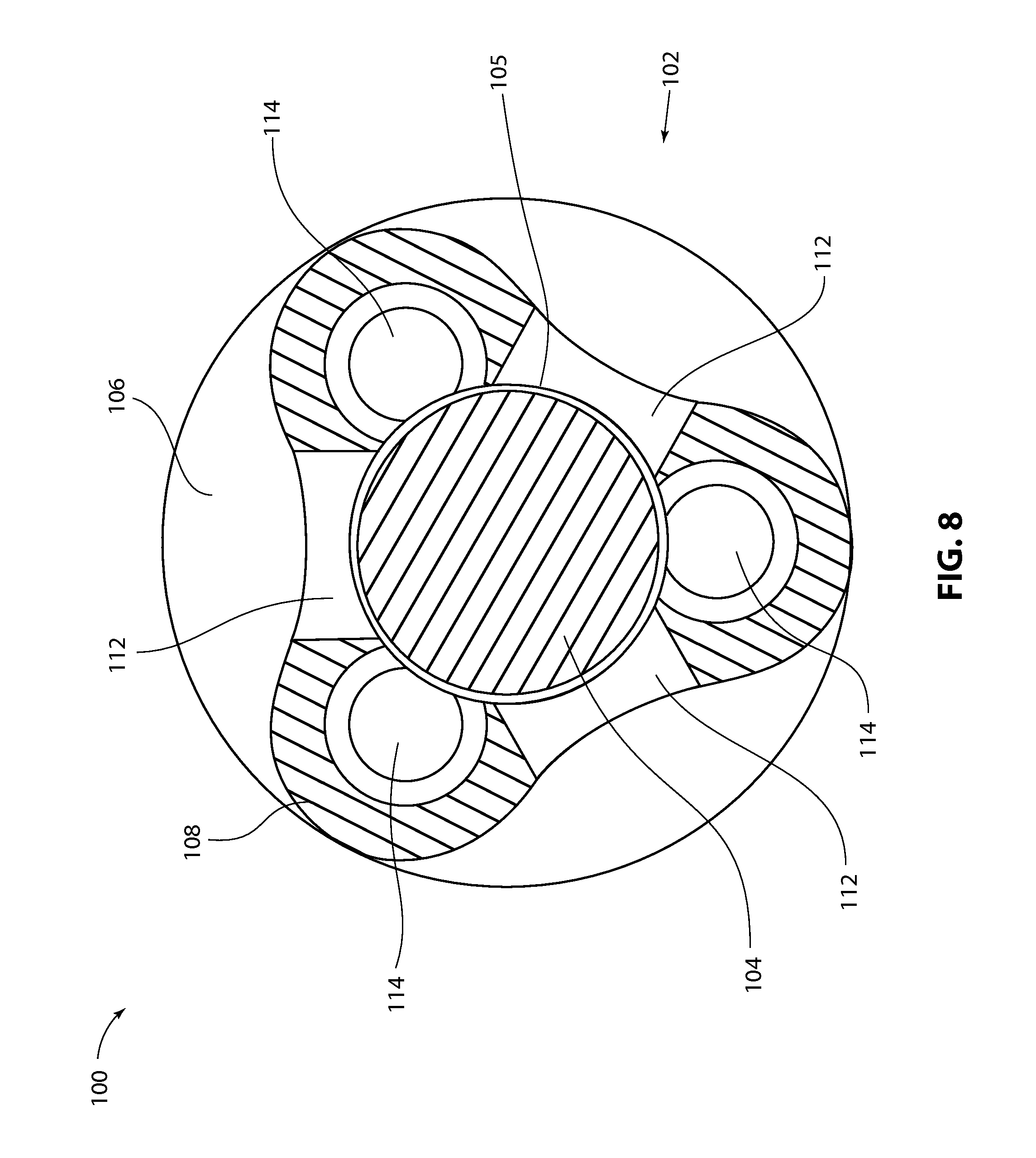
FIG. 8 is a cross-sectional view taken along Line 8-8 of FIG. 6;
FIG. 9 is a cross-sectional view taken along Line 9-9 of FIG. 6;
FIG. 10 is a perspective view showing a third exemplary embodiment of an implantable fluid interface;
FIG. 11 is an exploded perspective view showing the components of the fluid interface of FIG. 10;
FIG. 12 is another exploded perspective view taken from an opposite direction from that of FIG. 11;
FIG. 13 is an enlarged perspective view of the middle housing portion of the fluid interface of FIG. 10;
FIG. 14 is a proximally-looking end elevation view of the middle housing portion of the fluid interface of FIG. 10; and
FIG. 15 is a cross-sectional view taken along Line 15-15 of FIG. 10.
DETAILED DESCRIPTION
Referring to FIGS. 1-3, a first exemplary embodiment of an implantable occlusion resistant fluid interface 10 is shown. In this embodiment, fluid interface 10 includes three components: a top housing shell 12, a bottom housing shell 14, and a movable orifice member plate 16. In its assembled configuration, as shown in FIG. 1, plate 16 is sandwiched between top shell 12 and bottom shell 14, and is movably captivated therebetween. In this embodiment, top shell 12 and bottom shell 14 are manufactured to be identical pieces differing only in name.
Referring to FIG. 2, the main portion of bottom shell 14 is provided with an oval shaped inner wall 18, a U-shaped outer wall 20, and a recessed portion 22 located therebetween. The right side of bottom shell 14 is provided with a trough 24 that communicates with recessed portion 22. Thickened wall sections 26 are provided on either side of trough 24. Top shell 12 includes the same features as bottom shell 14. During the assembly of device 10, the outer wall 20 of bottom shell 14 is joined with outer wall 20 of top shell 12, and the thickened wall sections 26 of bottom shell 14 are joined with the thickened wall sections 26 of top shell 12. The joining process may include laser welding, ultrasonic welding, adhesive, or other suitable joining processes. Once top shell 12 is joined with bottom shelf 14, a catheter port 28 is formed at one end of device 10 by troughs 24, as shown in FIG. 1.
Referring to FIG. 3, a cross-section of device 10 taken along line 3-3 of FIG. 1 is shown. Once the top housing shell 12 and bottom housing shell 14 are joined together as previously described, their respective recessed portions 22 together form an internal housing cavity defined by the toroidal housing of assembled device 10. As can be seen in FIG. 3, the inner walls 18 of top shell 12 and bottom shell 14 do not extend as far towards the opposing shell as do outer walls 20. This arrangement leaves room for plate 16 to be movably received between top shell 12 and bottom shell 14 with additional space remaining above and/or below plate 16 between it and inner walls 18 of top shell 12 and bottom shell 14. This additional space not only allows plate 16 to move relative to the housing of device 10, but provides at least one oval shaped orifice 30 (also shown in FIG. 1) between the internal housing cavity and the exterior of the housing (in the center portion of the toroidal housing). It can be seen from FIG. 3 that plate 16 is sized such that when it moves laterally in either direction to contact the inside of outer walls 20, the opposite side of plate 16 still remains within the space between inner walls 18. This is also true when plate 16 moves in either direction longitudinally relative to top shell 12 and bottom shell 14.
Referring to FIG. 4, an enlarged portion of the cross-sectional view of FIG. 3 showing plate 16 is provided. In this exemplary embodiment, plate 16 is captivated between inner walls 18 of top housing shell 12 and bottom housing shell 14, and is allowed to float therebetween, as shown in FIGS. 3 and 4. As depicted in these figures, orifice 30 can exist above and/or below plate 30. It can be appreciated that a maximum orifice width W can be defined as the distance between the upper inner walls 18 and lower inner walls 18 minus the thickness of plate 16. This maximum orifice width W would occur on the opposite side of plate 16 when it rests against either the upper inner walls 18 or the lower inner walls 18. In FIG. 4, plate 16 is depicted as being in a central position with an orifice width W/2 above the plate and another orifice having width W/2 below the plate. Orifice or orifices 30 can also be defined as having a length of at least L, as shown in FIG. 4. The length L of orifice 30 can alternatively be defined in the longitudinal direction of device 10, or even as the length of the inside circumference of inner wall 18 of either the top housing shell 12 or bottom housing shell 14.
In some embodiments, the maximum orifice width is maintained at about 0.010 inches or less. In some embodiments, the maximum orifice width is maintained at about 0.003 inches or less. In other embodiments, a mixture of orifice sizes is used. Initial testing suggests that by keeping the maximum orifice width W to these small dimensions, tissue ingrowth and/or protein buildup that would otherwise clog orifice 30 can be impeded or eliminated. To increase the flow rate through orifice 30, it is desirable for the orifice to have a larger cross-section. The orifice cross-section is defined as being transverse to the fluid flow through the orifice. This can be accomplished by maintaining the orifice width W at 0.010 inches, 0.003 inches or less and increasing the length L to create an elongated orifice. In some embodiments of the inventiveness fluid interface, the orifice has an elongated transverse cross-section configured with a length that is at least four times the maximum width. In some embodiments, the orifice length is at least 10 times the maximum width. In some embodiments the orifice length is at least 100 times the maximum width. In the exemplary embodiment shown, the device is about 0.5 inches long, has an orifice length L of about 0.7 inches (taken along the inside circumference of inner walls 18) and a maximum width W of 0.003 inches. This yields an orifice 30 having an elongated transverse cross-section configured with a length L that is more than 200 times the maximum width W.
In addition to the elongated transverse cross-section of orifice 30, the movement of plate 16 relative to orifice or orifices 30 that it partially defines contributes to impeding or eliminating tissue ingrowth and/or protein buildup that would otherwise clog the orifice(s). In some cases when device 10 is implanted within a patient, plate 16 is continuously or at least periodically moving relative to inner walls 18. Such movement can cause the orifice to be self-cleaning. The movement can also create a varying orifice size, and therefore create variable regional fluid flow near the orifice. It is believed that such variable regional fluid flow, or flow instability, contributes to impeding or eliminating tissue and/or protein buildup in and around the orifice. Conversely, it is believed that a constant, non-varying fluid flow contributes to tissue and/or protein buildup.
In some embodiments, top housing shell 12, bottom housing shell 14 and orifice member plate 16 are formed from titanium. The outside of device 10 can be ultra-electropolished. To further inhibit orifice clogging, plate 16 can be nano-etched (roughened) to help prevent tissue and proteins from forming on plate 16. This can be accomplished with ion blasting, such as with a xenon ion gun, to form nano channels or ripples on plate 16. There will be less adsorbed proteins on the modified surfaces due to a decrease of the surface energy caused by the surface modification. In some embodiments, the nano-ripples are less than about 50 nm high. In some embodiments, the nano-ripples are about 10 nm high. Initial testing indicates that if the nano-ripples are created with a spacing of about 52 nm or less, adhesion of tissue and protein to plate 16 can be prevented. Some embodiments include varied nano sized surface curvatures. These surface treatments can be applied to other surfaces of device 10 and to surfaces of other devices disclosed herein.
In some embodiments, surface treatment(s) of plate 16 are purely mechanical, as described above, without any chemical treatments or changes to the stoichiometry of the device surfaces. Advantages of purely mechanical treatments include avoidance of degradation of the material of plate 16, and also the avoidance of additional regulatory issues, such as with the U.S. Food and Drug Administration (FDA).
As shown in FIG. 5, device 10 can be attached to one end of a catheter 32. In one embodiment, this is accomplished by welding a titanium mesh onto the neck or catheter port 28 of device 10, and then over molding the mesh with silicone to bond to catheter 32. Alternatively, a solid neck having one or more grooves 34, barbs or other recessed features may be used as the core in an over molding process. A silicon material having a higher durometer than the rest of the catheter 32 may be overmolded in the region of catheter port 28 as depicted in FIG. 5. An essentially seamless transition 36 between the catheter 32 and catheter port 28 can be created by matching the outer diameter of catheter port 28 with the outer diameter of catheter 32. This inhibits tissue ingrowth after implantation and also enables device 10 to be removed from a patient without tissue damage.
A fluid interface device 10 constructed according to aspects of the present disclosure can be located at the inlet end of a catheter, at the outlet end, or both, when the catheter is used to move fluid from one region of a patient to another.
The exterior surfaces of device 10 can be roughened to reduce surface tension. This in turn can alleviate air bubbles from adhering to device 10 during insertion of the device into the patient, which would otherwise cause adverse effects.
In an alternative embodiment (not shown), the principles of the present disclosure can be used to construct a device having a movable ball instead of a movable plate. In such an embodiment, the ball can partially define one or more orifices, such as round holes located on opposite sides of a housing.
Referring to FIGS. 6-9, a second exemplary embodiment of an implantable occlusion resistant fluid interface 100 is shown. In this embodiment, fluid interface 100 includes an elongated housing 102 and a cylindrical agitator 104 captivated within a central void 105 inside housing 102. As best seen in FIGS. 6 and 7, housing 102 comprises a proximal portion 106, a middle portion 108, and a distal portion 110. Housing portions 106, 108 and 110 may be separate components that are joined together during assembly, or one or more of the components may be integrally formed. Proximal housing portion 106 comprises a fitting configured to couple to a catheter. A central lumen through proximal portion 106 is in fluid communication with central void 105 inside middle portion 108. Middle portion 108 is provided with three elongated slot 112 that provide fluid communication between central void 105 inside middle portion 108 and the exterior of device 100.
Referring to FIG. 8, middle housing portion 108 as a transverse cross-section that is generally triangular in shape, but has rounded apexes and inwardly curving side faces. Each apex or lobe is provided with a longitudinally extending channel 114 that overlaps with and is in fluid communication with central void 105. In some embodiments, agitator 104 has a diameter of 0.059 inches and central void 105 has a diameter of 0.062 inches, leaving an even gap of about 0.0015 inches between agitator 104 and central void 105 on all sides, or a maximum gap of about 0.003 inches on one side. In some embodiments, channels 114 have a diameter of 0.032 inches.
As best seen in FIGS. 6 and 9, distal housing portion 110 is generally hemispherical in shape and is contoured to mate smoothly with the apexes and inwardly curving side faces of middle housing portion 108. Similarly, proximal housing portion 106 has a larger cylindrical portion that is also contoured to mate smoothly with the apexes and inwardly curving side faces of middle housing portion 108. The outer diameter of the larger cylindrical portion of proximal housing portion 106 may be identical to the outer diameter of the catheter it mates with. With the above described contours and dimensions, device 100 may be more easily implanted and/or removed, and may reside within a patient without causing trauma to adjacent tissue.
Referring to FIG. 9, a longitudinal cross-section of device 100 is shown. As can be seen, the length of agitator 104 is shorter than the length of central void 105 so that agitator 104 may slide longitudinally within central void 105. With this arrangement, agitator 104 may passively move within central void 105 when the orientation of device 100 changes and or the direction of fluid flow through central void 105 changes. For example, when the distal end 110 of device 100 is lowered and or fluid is flowing in a distal direction, agitator 104 may move distally. Conversely, when the distal end 110 of device 100 is raised and or fluid is flowing in a proximal direction, agitator 104 may move proximally. Such changes in fluid direction may be caused by the use of a fluid bulb in fluid communication with the catheter (not shown) to back flush the catheter system. Longitudinal movement of agitator 104 may serve to disrupt any tissue ingrowth and or protein build up that may be starting to occur within device 100, and or may serve to change the fluid flow paths when the fluid flow changes direction, thereby inhibiting tissue ingrowth and or protein build up.
In the exemplary embodiment shown in FIGS. 6-9, device 100 has an overall length of about 0.65 inches and has a maximum diameter of about 0.135 inches.
Referring to FIGS. 10-15, a third exemplary embodiment of an implantable occlusion resistant fluid interface 200 is shown. In this embodiment, fluid interface 200 includes a housing 202 and a rotor 204 (shown in FIG. 11) rotatably disposed within a central cavity 205 inside housing 202. As best seen in FIGS. 11 and 12, housing 202 comprises a proximal portion 206, a middle portion 208, and a distal end cap 210. Housing portions 206, 208 and 210 may be separate components that are joined together during assembly, or one or more of the components may be integrally formed. Proximal housing portion 206 comprises a double-barbed fitting configured to couple to a catheter. A central lumen 212 through proximal portion 206 is in fluid communication through apertures 214 with central void 205 inside middle portion 208.
Referring to FIG. 11, rotor 204 comprises a series of radially extending turbine blades 216 disposed around its distal end. Rotor 204 is received within central cavity 205 inside middle housing portion 208 and captivated therein when distal cap 210 is attached to the distal end of middle housing portion 208 during assembly. Rotor 204 is allowed to freely rotate about a longitudinal axis by virtue of its being mounted between two ball bearings 218, which in some embodiments are made of sapphire. The distal most ball 218 is located between a circular recess 220 in the distal end of rotor 204 and a circular recess 222 on the proximal side of distal end cap 210 (shown in FIG. 12.) The proximal most ball 218 is located between a circular recess 224 on the proximal end of rotor 204 (shown in FIG. 12) and a circular recess 226 located within middle housing portion 208 (shown in FIGS. 13 and 14.) The vent holes 228 are provided through distal end cap 210 to allow fluid to flow from central cavity 205 past turbine blades 216 and out through vent holes 228 to the exterior of device 200, and or along the same path in the opposite direction. The flow of fluid past turbine blades 216 causes rotor 204 to rotate about its longitudinal axis. The distal most edges of turbine blades 216 may be located very close to vent holes 228 (such as within about 0.005 inches or less) such that the movement of turbine blades 216 disrupts tissue, protein and other matter from adhering to end cap 210.
Referring to FIG. 14, a longitudinal cross-section of device 200 is shown. Representative fluid flow is depicted with arrows between point A and point B. Fluid flow may also be in the opposite direction.
In the exemplary embodiment shown in FIGS. 10-15, device 200 has an overall length of about 0.54 inches and has a maximum diameter of about 0.125 inches.
According to aspects of the invention, clog-resistant fluid orifices may be formed between a passively movable component and a device housing, wherein the movable component is not part of a valve or other structure. In some embodiments, components forming an orifice, such as a movable component and a housing, may comprise dissimilar metals. The dissimilar metals can create an electrical potential between the components that changes the hydrophobicity of the surface(s). This in turn can repel proteins and or inhibit tissue ingrowth. In some embodiments, the electrical potential is tuned to attract particular biomarkers that the device is configured to sample.
According to aspects of the invention, the exemplary fluid interface devices disclosed herein can be used in various applications. For example, the devices may be used in hydrocephalus drainage systems (such as for brain injuries), in hemodialysis systems, in fluid sampling systems, in wound care (such as for Extremity Compartment Syndrome, reconstructive flaps, burns, surgical incisions, etc.) The devices may also be used for drug delivery, such as long-term chemotherapeutics, localized drug delivery to tumor sites, delivery of antibiotics, pain medications, regenerative growth factors, etc. In some applications such as hydrocephalus drainage systems, typical fluid flow rates can be around 2 milliliters per minute or less. In other applications, fluid flow rates may be about 40 ml/min. unassisted and 400 ml/min. under assistance, such as suction or pressure.
As for additional details pertinent to the present invention, materials and manufacturing techniques may be employed as within the level of those with skill in the relevant art. The same may hold true with respect to method-based aspects of the invention in terms of additional acts commonly or logically employed. Also, it is contemplated that any optional feature of the inventive variations described may be set forth and claimed independently, or in combination with any one or more of the features described herein. Likewise, reference to a singular item, includes the possibility that there are plural of the same items present. More specifically, as used herein and in the appended claims, the singular forms "a," "and," "said," and "the" include plural referents unless the context clearly dictates otherwise. It is further noted that the claims may be drafted to exclude any optional element. As such, this statement is intended to serve as antecedent basis for use of such exclusive terminology as "solely," "only" and the like in connection with the recitation of claim elements, or use of a "negative" limitation. Unless defined otherwise herein, all technical and scientific terms used herein have the same meaning as commonly understood by one of ordinary skill in the art to which this invention belongs. The breadth of the present invention is not to be limited by the subject specification, but rather only by the plain meaning of the claim terms employed.
* * * * *
D00000
D00001
D00002
D00003
D00004
D00005
D00006
D00007
D00008
D00009
D00010
D00011
D00012

D00013

D00014

D00015

XML
uspto.report is an independent third-party trademark research tool that is not affiliated, endorsed, or sponsored by the United States Patent and Trademark Office (USPTO) or any other governmental organization. The information provided by uspto.report is based on publicly available data at the time of writing and is intended for informational purposes only.
While we strive to provide accurate and up-to-date information, we do not guarantee the accuracy, completeness, reliability, or suitability of the information displayed on this site. The use of this site is at your own risk. Any reliance you place on such information is therefore strictly at your own risk.
All official trademark data, including owner information, should be verified by visiting the official USPTO website at www.uspto.gov. This site is not intended to replace professional legal advice and should not be used as a substitute for consulting with a legal professional who is knowledgeable about trademark law.