Method for manufacturing dental prosthesis
Fujimoto , et al. Ja
U.S. patent number 10,182,894 [Application Number 15/119,552] was granted by the patent office on 2019-01-22 for method for manufacturing dental prosthesis. This patent grant is currently assigned to GC CORPORATION. The grantee listed for this patent is GC CORPORATION. Invention is credited to Tatsuya Fujimoto, Go Mashio, Daisuke Ohta, Masatoshi Yoshinaga.


| United States Patent | 10,182,894 |
| Fujimoto , et al. | January 22, 2019 |
Method for manufacturing dental prosthesis
Abstract
An object is to provide a method for manufacturing a dental prosthesis consisting of a plurality of layers with high productivity. The method for manufacturing a dental prosthesis comprises: filling a cavity (21a) formed in a mold which has a shape of the dental prosthesis with a layered material body (23) that is made by layering materials (23a, 23b) corresponding to the plurality of layers; and after this filling, rotating the mold on a material inlet (21b) of the mold and cutting the materials.
| Inventors: | Fujimoto; Tatsuya (Tokyo, JP), Yoshinaga; Masatoshi (Tokyo, JP), Mashio; Go (Tokyo, JP), Ohta; Daisuke (Tokyo, JP) | ||||||||||
|---|---|---|---|---|---|---|---|---|---|---|---|
| Applicant: |
|
||||||||||
| Assignee: | GC CORPORATION (Tokyo,
JP) |
||||||||||
| Family ID: | 53878307 | ||||||||||
| Appl. No.: | 15/119,552 | ||||||||||
| Filed: | February 18, 2015 | ||||||||||
| PCT Filed: | February 18, 2015 | ||||||||||
| PCT No.: | PCT/JP2015/054385 | ||||||||||
| 371(c)(1),(2),(4) Date: | August 17, 2016 | ||||||||||
| PCT Pub. No.: | WO2015/125807 | ||||||||||
| PCT Pub. Date: | August 27, 2015 |
Prior Publication Data
| Document Identifier | Publication Date | |
|---|---|---|
| US 20170056139 A1 | Mar 2, 2017 | |
Foreign Application Priority Data
| Feb 21, 2014 [JP] | 2014-031851 | |||
| Current U.S. Class: | 1/1 |
| Current CPC Class: | A61C 13/081 (20130101); A61C 13/08 (20130101); A61C 13/09 (20130101); B29C 41/22 (20130101); B29C 41/04 (20130101); A61C 13/20 (20130101); B29L 2031/753 (20130101); B29K 2101/12 (20130101) |
| Current International Class: | A61C 13/08 (20060101); B29C 41/04 (20060101); B29C 41/22 (20060101); A61C 13/09 (20060101); A61C 13/20 (20060101) |
References Cited [Referenced By]
U.S. Patent Documents
| 1511458 | October 1924 | Gibson |
| 6648646 | November 2003 | Sato |
| 2008/0023872 | January 2008 | Criel |
| 2009/0239199 | September 2009 | Cadario et al. |
| 1197528 | Apr 2005 | CN | |||
| 1960849 | May 2007 | CN | |||
| 1988995 | Jun 2007 | CN | |||
| 5734844 | Feb 1982 | JP | |||
| 06269466 | Sep 1994 | JP | |||
| 2010-503474 | Feb 2010 | JP | |||
| 2013066282 | May 2013 | WO | |||
Other References
|
International Search Report dated Apr. 28, 2015; PCT/JP2015/054385. cited by applicant. |
Primary Examiner: Grun; Robert J
Attorney, Agent or Firm: Ladas & Parry LLP Thompson; Loren K.
Claims
The invention claimed is:
1. A method for manufacturing a dental prosthesis that has a plurality of layers, the method comprising: filling a cavity that has a shape of the dental prosthesis with a layered material body that is made by layering at least two kinds of materials corresponding to the plurality of layers, the cavity being formed in a mold, by injecting/casting the materials into the mold at the same time; and after said filling, rotating the mold on a material inlet of the mold and cutting the materials.
2. The method for manufacturing a dental prosthesis according to claim 1, wherein all of an outer circumference of the dental prosthesis is covered by one kind of the layers.
Description
TECHNICAL FIELD
This invention relates to a method for manufacturing a dental prosthesis, and more particularly relates to a method for manufacturing a dental prosthesis including a plurality of layers.
BACKGROUND ART
A dental prosthesis such as a crown is one means for artificially reproducing functions of a lost natural tooth. An exterior of a natural tooth is formed hard by enamel and has a unique texture. A natural tooth affects not only the function of mastication but also impression of a human's face. Thus, preferably, a dental prosthesis having as close color and texture to a natural tooth as possible is used. As one method for improving so-called aesthetics of a dental prosthesis as described, for example, Patent Literature 1 proposes a dental prosthesis that consists of a plurality of layers having an inside layer of low transparency and an outside layer of high transparency as disclosed. According to this, the inside layer shields the color of an abutment from the exterior view, and the aesthetic property can be improved by the outer layer of high transparency and the inside layer seen through the outer layer.
Patent Literature 1 discloses that the inner layer is cast first and then, the outer layer is cast on the inner layer as a method for manufacturing such a dental prosthesis having a plurality of layers.
CITATION LIST
Patent Literature
Patent Literature 1: JP H6-269466A
SUMMARY OF INVENTION
Technical Problem
There is a problem that it takes some effort to form a dental prosthesis consisting of a plurality of layers with the manufacturing method as described in Patent Literature 1, and it is demanded that the productivity be improved.
In view of the above problem, an object of this invention is to provide a method for manufacturing a dental prosthesis consisting of a plurality of layers with high productivity.
Solution to Problem
The present invention will be described below. Here, reference signs attached to the drawings are described together in parentheses for easy understanding. However, the present invention is not limited thereto.
The invention of claim 1 is a method for manufacturing a dental prosthesis (10) that has a plurality of layers (11, 12), the method comprising: filling a cavity (21a) that has a shape of the dental prosthesis with a layered material body (23) that is made by layering materials (23a, 23b) corresponding to the plurality of layers, the cavity being formed in a mold (21); and after said filling, rotating the mold on a material inlet (21b) of the mold and cutting the materials.
In the invention of claim 2, all of an outer circumference of the dental prosthesis is covered by one kind of the layers in the method for manufacturing a dental prosthesis according to claim 1.
Advantageous Effects of Invention
According to the present invention, the productivity can be improved because it is not necessary to individually make a plurality of layers of a dental prosthesis but the layers can be formed at the same time.
BRIEF DESCRIPTION OF DRAWINGS
FIG. 1 is an exterior perspective view of a dental prosthesis 10.
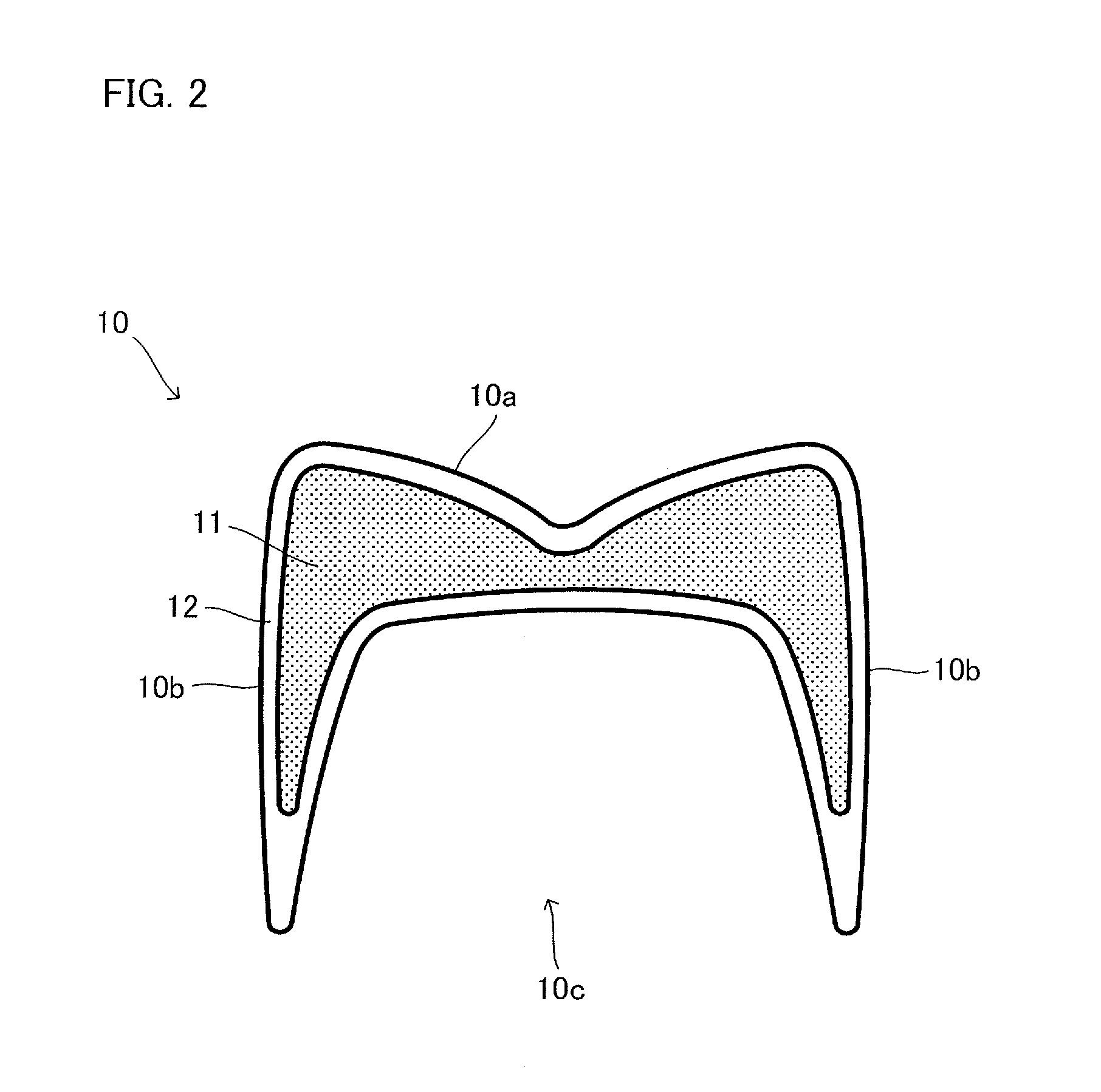
FIG. 2 is a cross-sectional view of the dental prosthesis 10.
FIG. 3 shows a wax pattern 20.
FIG. 4 is a view to explain the scene where a mold 21 is attached to a filling device 22.
FIG. 5 is an exterior perspective view of a layered material body 23.
FIG. 6 is a view to explain one scene of molding the dental prosthesis 10.
FIG. 7 is a view to explain a process of filling with materials.
FIG. 8 is a view to explain the scene where filling with the materials is completed.
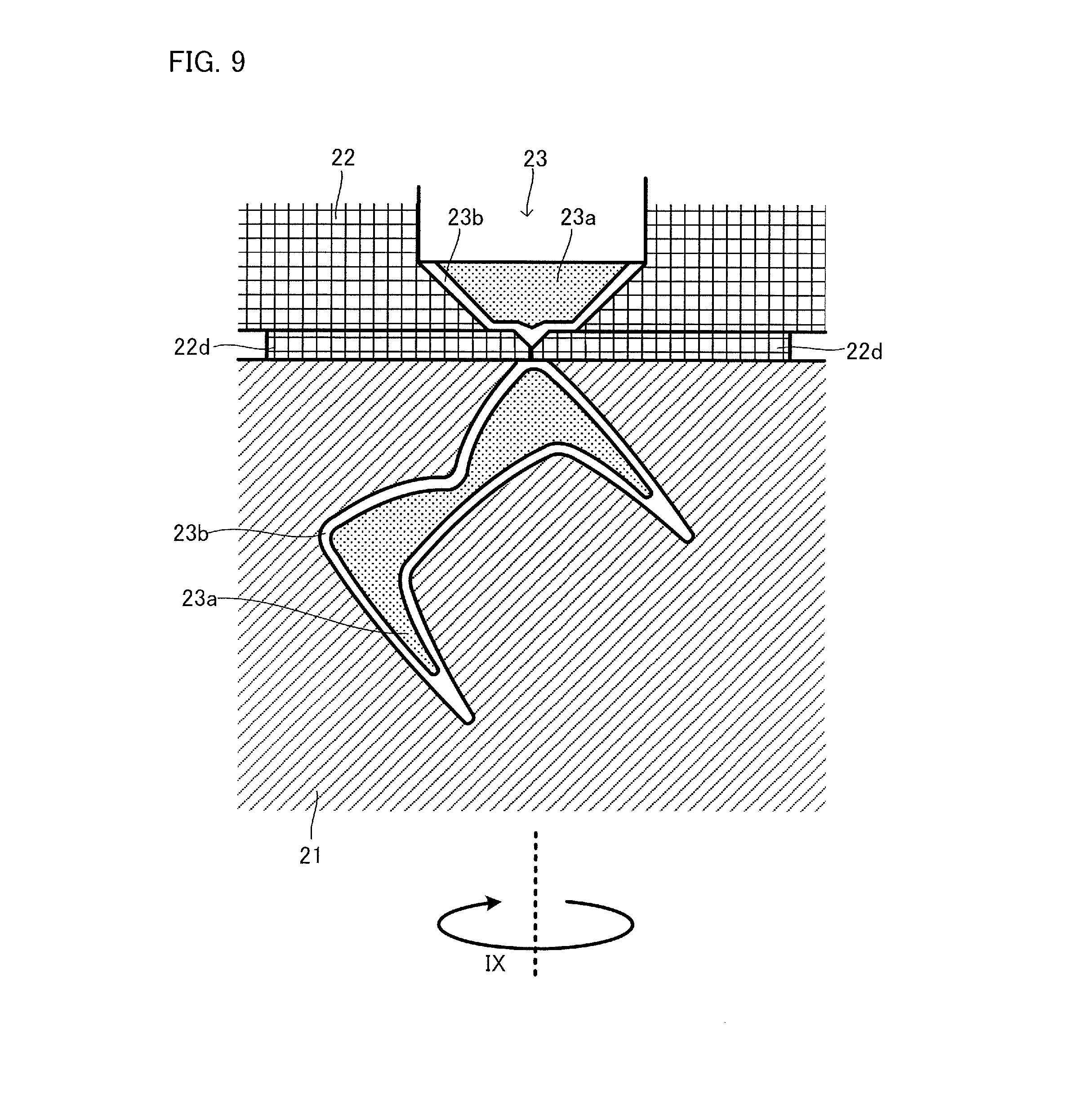
FIG. 9 is a view to explain the scene of rotating the mold 21 and cutting the materials.
DESCRIPTION OF EMBODIMENTS
The above described operation and advantage of the present invention are made clear by the embodiments described as follows. The present invention will be described below based on the embodiments shown in the drawings. However, the present invention is not limited to these embodiments.
Before describing a method for manufacturing a dental prosthesis, one example of a shape of a dental prosthesis manufactured by this method is described. FIG. 1 is an exterior perspective view of a dental prosthesis 10 that is the example. FIG. 2 is a cross-sectional view taken along the line II-II in FIG. 1 in the direction of the arrows. As is seen from FIGS. 1 and 2, the dental prosthesis 10 of this example is a crown. Intraoral side surface 10a and side surface 10b have shapes that imitate a natural tooth. In contrast, the side of the dental prosthesis 10 which faces the intraoral side surface 10a is an abutment side surface 10c that has a shape like a recess. An abutment is inserted to this portion, which is shaped to be like a recess, to retain the dental prosthesis 10 in an oral cavity.
The dental prosthesis 10 of this example is formed to have an inner layer 11 and an outer layer 12 as is seen from FIG. 2.
The inner layer 11 has color close to a natural tooth, and functions so that the dental prosthesis 10 resembles a natural tooth as a whole. The inner layer 11 is structured so as to hide an abutment from the outer view when the dental prosthesis 10 is attached to the abutment. Thereby, impression closer to a natural tooth can be given because the abutment cannot be seen.
In view of the above, the inner layer 11 has color close to a natural tooth, and is constituted by a material whose transparency is kept low. Examples of a material used for the inner layer 11 in view of this include thermoplastic resin, ceramics and glass ceramics. Ceramics and glass ceramics are preferable among them in view of the strength and aesthetics of the dental prosthesis.
The outer layer 12 is a layer that is formed so as to surround the outer circumference of the inner layer 11. In this example, the outer layer 12 is layered around all the circumference of the inner layer 11. The outer layer 12 has a function of making texture of the outer surface of the dental prosthesis 10 close to that of a natural tooth. Because of this, the outer layer 12 has color close to a natural tooth, and is constituted by a material whose transparency is higher than the inner layer 11.
Examples of a material used for the outer layer 12 in view of this include thermoplastic resin, ceramics and glass ceramics.
Ceramics and glass ceramics are preferable among them in view of the strength and aesthetics of the dental prosthesis.
Here, in view of easy molding and improvement of the aesthetics, preferably combination of materials of the inner layer 11 and the outer layer 12 is not combination of largely different materials in property such as thermoplastic resin and ceramics. It is more preferable to employ combination of different materials of similar properties.
Specific color of the inner layer 11 and the outer layer 12 is adjusted according to a patient's natural tooth and any other requirements. Such adjustment is carried out by a known method.
The dental prosthesis 10 of this example has the structure that all the circumference of the inner layer 11 is surrounded only by one kind of a layer (only by the outer layer 12) and thus the border between the inner layer 11 and the outer layer 12 is not exposed. Therefore, such faults can be held down that spots intrude between the inner layer 11 and the outer layer 12, which lowers the aesthetics.
Next, one embodiment will be described concerning the method for manufacturing a dental prosthesis that is formed by having a plurality of layers like the dental prosthesis 10. Here, an example of manufacturing the dental prosthesis 10 is described. However, the present invention is not necessarily limited thereto, and for example, a dental prosthesis of such an embodiment can be manufactured that the outer circumference is not formed by one kind of a layer only, and part of the inner layer 11 is exposed. FIGS. 3 to 9 are views for explanation. These drawings are conceptual drawings shown to explain this manufacturing method, and are not drawings showing modes and behaviors of materials precisely.
In the manufacturing method of this embodiment, first, a wax pattern 20 of the dental prosthesis 10 that is to be manufactured is made as shown in FIG. 3 by a known method. In making, an end surface for an opening 20a and a passage forming part 20b which are for forming a passage where materials pass when a mold 21 (see FIG. 4) is made are provided together.
Next, the wax pattern 20 is invested in dental investment. After the dental investment is cured, the wax pattern 20 is liquated out and combusted, to be removed. Thereby, the mold 21 shown in FIG. 4 is made. Thus, in the mold 21, a cavity 21a having a shape of the dental prosthesis 10, material inlet 21b where materials are forced, and a passage 21c that is a passage linking the material inlet 21b with the cavity 21a are formed.
The mold 21 formed like the above is attached to a filling device 22 as shown in FIG. 4. The filling device 22 includes a material insertion part 22a that is a space for disposing a block-like layered material body 23 (see FIG. 5), a reduced diameter part 22b that is a space whose diameter is continuously reduced from the material insertion part 22a, a material inlet 22c for filling the mold 21 with materials at an end part of the reduced diameter part 22b, and a pressing member that presses the layered material body 23 toward the material inlet 22e side, which is not depicted. Here, the filling device 22 is provided with a shutter 22d that closes the material inlet 22c and cuts materials. The filling device 22 is further structured so that, assuming that a direction parallel to the pressing direction is an axis, the mold 21 can be rotated on the axis.
When the mold 21 is attached to the filling device 22, as shown in FIG. 4, they are arranged so that the material inlet 22c of the filling device 22 communicates with the material inlet 21b of the mold 21.
FIG. 5 is a perspective view of the block-like layered material body 23, which is used as materials that form the dental prosthesis 10. In this embodiment, the layered material body 23 is a columnar shape correspondingly to the shape of the material insertion part 22a of the filling device 22. A material for an inner layer 23a and a material for an outer layer 23b are layered in a direction along the axis of the columnar shape. The materials each are to constitute the inner layer 11 and the outer layer 12, and are as described above.
Next, as shown in FIG. 6, the layered material body 23 is arranged in the material insertion part 22a of the filling device 22. At this time, the material for an outer layer 23b faces the mold 21 side and the material for an inner layer 23a faces the opposite side to the mold 21 (a side of the pressing member not shown). The layered material body 23 is heated to a predetermined temperature that is lower than melting temperature in order to decrease the viscosity.
The layered material body 23 is pressed by the pressing member not shown from the state shown in FIG. 6 in the direction indicated by VI in FIG. 6. Thereby, the layered material body 23, whose viscosity is decreased, passes through the reduced diameter part 22b and the material inlet 22c, enters the mold 21 through the material inlet 21b, and passes through the passage 21c, and the cavity 21a is filled therewith as shown in FIG. 7.
At this time, as shown in FIG. 7, the cavity 21a is filled with the layered material body 23, whose viscosity is decreased, as the material for an inner layer 23a, which is in the side further from the mold 21, moves forward inside the material for an outer layer 23b, which is in the side closer to the mold 21, the material for an outer layer 23b covers the inner circumferential face of the cavity 21a, and the material for an inner layer 23a moves forward inside the covered inner circumferential face. Thereby, as shown in FIG. 8, when filling (pressing) is completed, the shape and the layer structure of the dental prosthesis 10 to be obtained are simultaneously formed.
Under the state shown in FIG. 8, the materials communicate between the mold 21 side and the filling device 22 side. Thus, it is necessary to isolate the mold 21 from the filling device 22. Just pulling or sliding might bring the situation where the material for an inner layer 23a is exposed outside at this portion. In contrast, in the manufacturing method of this embodiment, as shown in FIG. 9, the mold 21 is rotated on the pressing axis (the axis of the pressing) as the center as indicated by IX in FIG. 9, and further, the shutter 22d provided for the filling device 22 is closed; whereby the material inlet 22c is closed, the materials are cut, and the mold 21 is isolated from the filling device 22. Thereby, the material for an outer layer 23b covers the material for an inner layer 23a even at the portion of the material inlet 21b of the mold 21, and the material for an inner layer 23a can be prevented from being exposed.
At this time, the number of rotations of the mold 21 is preferably 1 rpm to 100 rpm. More preferably, 10 rpm to 70 rpm. Less than 1 rpm of the number of rotations results in bad productivity More than 100 rpm of the number of rotations might make the above described effect deteriorate.
The materials with which the mold 21 is filled are cooled down and separated from the mold, and then the dental prosthesis 10 may be taken out.
According to the manufacturing method as described above, a plurality of layers can be formed just once simultaneously, and a dental prosthesis can be manufactured efficiently. When the mold is removed from the filling device, the mold 21 is rotated and the shutter 22d is used as described above; thereby the material for an inner layer 23a can be properly arranged inside the material for an outer layer 23b even at the portion of the material inlet.
In this embodiment, an example of making the mold 21 using the wax pattern 20 is described in view of matching an individual patient. This invention is not limited to this example, and when a dental prosthesis of an embodiment for multiple uses which has an average shape is manufactured, the above method may be carried out with using a die as a mold with which the dental prosthesis of an embodiment for multiple uses can be obtained.
REFERENCE SIGNS LIST
10 dental prosthesis
11 inner layer
12 outer layer
20 wax pattern
21 mold
21a cavity
21b material inlet
21c passage
22 filling device
22a material insertion part
22b reduced diameter part
22c material inlet
22d shutter
23 layered material body
23a material for an inner layer
23b material for an outer layer
* * * * *
D00000
D00001
D00002
D00003
D00004
D00005
D00006
D00007
D00008
D00009
XML
uspto.report is an independent third-party trademark research tool that is not affiliated, endorsed, or sponsored by the United States Patent and Trademark Office (USPTO) or any other governmental organization. The information provided by uspto.report is based on publicly available data at the time of writing and is intended for informational purposes only.
While we strive to provide accurate and up-to-date information, we do not guarantee the accuracy, completeness, reliability, or suitability of the information displayed on this site. The use of this site is at your own risk. Any reliance you place on such information is therefore strictly at your own risk.
All official trademark data, including owner information, should be verified by visiting the official USPTO website at www.uspto.gov. This site is not intended to replace professional legal advice and should not be used as a substitute for consulting with a legal professional who is knowledgeable about trademark law.