Multi-pivot hinge
Tazbaz , et al. J
U.S. patent number 10,174,534 [Application Number 14/606,979] was granted by the patent office on 2019-01-08 for multi-pivot hinge. This patent grant is currently assigned to Microsoft Technology Licensing, LLC. The grantee listed for this patent is Microsoft Technology Licensing, LLC. Invention is credited to Brian Bitz, John Campbell, Bonggwon Ji, Jeff Liao, Errol Mark Tazbaz, Jingjiang Zhang.


| United States Patent | 10,174,534 |
| Tazbaz , et al. | January 8, 2019 |
Multi-pivot hinge
Abstract
The description relates to devices, such as computing devices that have hinged portions. One example can include a first portion and a second portion. This example can also include a sequential multi-pivot hinge assembly rotatably securing the first portion and the second portion. The sequential multi-pivot hinge assembly can include a first set of links configured to control a relative order of rotation around individual axes of rotation of the sequential multi-pivot hinge assembly when the first and second portions are being rotated away from one another and a second different set of links configured to control the relative order of rotation around the individual axes of rotation of the sequential multi-pivot hinge assembly when the first and second portions are being rotated toward one another.
| Inventors: | Tazbaz; Errol Mark (Bellevue, WA), Bitz; Brian (Sherwood, OR), Campbell; John (Puyallup, WA), Ji; Bonggwon (Hangzhou, CN), Liao; Jeff (Hangzhou, CN), Zhang; Jingjiang (Hangzhou, CN) | ||||||||||
|---|---|---|---|---|---|---|---|---|---|---|---|
| Applicant: |
|
||||||||||
| Assignee: | Microsoft Technology Licensing,
LLC (Redmond, WA) |
||||||||||
| Family ID: | 55410195 | ||||||||||
| Appl. No.: | 14/606,979 | ||||||||||
| Filed: | January 27, 2015 |
Prior Publication Data
| Document Identifier | Publication Date | |
|---|---|---|
| US 20160215541 A1 | Jul 28, 2016 | |
| Current U.S. Class: | 1/1 |
| Current CPC Class: | G06F 1/1616 (20130101); E05D 7/00 (20130101); E05D 3/14 (20130101); H04M 1/022 (20130101); G06F 1/1681 (20130101) |
| Current International Class: | E05D 3/06 (20060101); E05D 3/14 (20060101); E05D 7/00 (20060101); G06F 1/16 (20060101); H04M 1/02 (20060101) |
References Cited [Referenced By]
U.S. Patent Documents
| 3289877 | December 1966 | Hans |
| 4355666 | October 1982 | Torii |
| 4611710 | September 1986 | Mitsufuji |
| 4617699 | October 1986 | Nakamura |
| 4711046 | December 1987 | Herrgord |
| 4845809 | July 1989 | Pillifant, Jr. |
| 5056192 | October 1991 | Grass |
| 5229921 | July 1993 | Bohmer |
| 5448799 | September 1995 | Stein, Jr. |
| 5456195 | October 1995 | Ozaku et al. |
| 5509590 | April 1996 | Medeiros, Jr. |
| 5796575 | August 1998 | Podwalny et al. |
| 5845366 | December 1998 | Kuroda |
| 5987704 | November 1999 | Tang |
| 6223393 | May 2001 | Knopf |
| 6421235 | July 2002 | Ditzik |
| 6470532 | October 2002 | Rude |
| 6505382 | January 2003 | Lam et al. |
| 6527036 | March 2003 | Welsh |
| 6754081 | June 2004 | Rude et al. |
| 6757160 | June 2004 | Moore et al. |
| 6831229 | December 2004 | Maatta et al. |
| 6952861 | October 2005 | Ynosencio |
| 6966435 | November 2005 | Weiser et al. |
| 7140074 | November 2006 | Han et al. |
| 7155266 | December 2006 | Stefansen |
| 7227741 | June 2007 | Garel et al. |
| 7251129 | July 2007 | Lee et al. |
| 7293380 | November 2007 | Repecki |
| 7418766 | September 2008 | Nelson et al. |
| 7520025 | April 2009 | Hung |
| 7584524 | September 2009 | Jung |
| 7636985 | December 2009 | Greenbank |
| 7758082 | July 2010 | Weigel et al. |
| 7966694 | June 2011 | Estlander |
| 8024843 | September 2011 | Endo et al. |
| 8032988 | October 2011 | Lai et al. |
| 8122970 | February 2012 | Palen |
| 8170630 | May 2012 | Murayama et al. |
| 8441791 | May 2013 | Bohn et al. |
| 8451601 | May 2013 | Bohn et al. |
| 8467838 | June 2013 | Griffin et al. |
| 8590857 | November 2013 | Chen et al. |
| 8624844 | January 2014 | Behar et al. |
| 8649166 | February 2014 | Wu |
| 8687354 | April 2014 | Uchiyama et al. |
| 8687359 | April 2014 | Theobald et al. |
| 8713759 | May 2014 | Cai |
| 8743538 | June 2014 | Ashcraft et al. |
| 8776319 | July 2014 | Chang et al. |
| 8796524 | August 2014 | Deck |
| 8797727 | August 2014 | Ashcraft et al. |
| 8804324 | August 2014 | Bohn et al. |
| 8826495 | September 2014 | Jauvtis et al. |
| 8843183 | September 2014 | Griffin et al. |
| 8854834 | October 2014 | O'Connor et al. |
| 9047055 | June 2015 | Song |
| 9243432 | January 2016 | Lee |
| 9268372 | February 2016 | Hsu |
| 9290976 | March 2016 | Horng |
| 9371676 | June 2016 | Rittenhouse |
| 9411365 | August 2016 | Tanner et al. |
| 9625947 | April 2017 | Lee et al. |
| 9625953 | April 2017 | Bitz et al. |
| 9625954 | April 2017 | Campbell et al. |
| 2004/0091101 | May 2004 | Park et al. |
| 2004/0266239 | December 2004 | Kurokawa |
| 2005/0122671 | June 2005 | Homer |
| 2005/0155182 | July 2005 | Han et al. |
| 2006/0005356 | January 2006 | Amano et al. |
| 2006/0046792 | March 2006 | Hassemer et al. |
| 2006/0079277 | April 2006 | Ditzik |
| 2007/0039132 | February 2007 | Jung et al. |
| 2007/0049376 | March 2007 | Cho et al. |
| 2007/0107163 | May 2007 | Barnett |
| 2007/0117600 | May 2007 | Robertson et al. |
| 2007/0247799 | October 2007 | Nie et al. |
| 2008/0112113 | May 2008 | Sawadski et al. |
| 2008/0174089 | July 2008 | Ekberg |
| 2008/0250604 | October 2008 | Chen et al. |
| 2009/0147458 | June 2009 | Wang et al. |
| 2010/0154171 | June 2010 | Lee et al. |
| 2010/0232100 | September 2010 | Fukuma |
| 2011/0000136 | January 2011 | Brun |
| 2011/0099756 | May 2011 | Chen |
| 2011/0177850 | July 2011 | Griffin et al. |
| 2011/0292605 | December 2011 | Chen |
| 2012/0046076 | February 2012 | Masser et al. |
| 2012/0120618 | May 2012 | Bohn |
| 2012/0120627 | May 2012 | O'connor et al. |
| 2012/0127471 | May 2012 | Urushidani |
| 2012/0137471 | June 2012 | Kujala |
| 2012/0147542 | June 2012 | Kim |
| 2012/0206893 | August 2012 | Bohn et al. |
| 2012/0272481 | November 2012 | Ahn et al. |
| 2012/0279014 | November 2012 | Carlsson et al. |
| 2012/0307472 | December 2012 | Bohn et al. |
| 2013/0014346 | January 2013 | Ahn et al. |
| 2013/0046492 | February 2013 | Westergaard |
| 2013/0081229 | April 2013 | Hirano |
| 2013/0111704 | May 2013 | Mitsui |
| 2013/0135809 | May 2013 | Uchiyama et al. |
| 2013/0139355 | June 2013 | Lee et al. |
| 2013/0152342 | June 2013 | Ahn et al. |
| 2013/0194741 | August 2013 | Uchiyama et al. |
| 2013/0216740 | August 2013 | Russell-Clarke |
| 2013/0219663 | August 2013 | Cai |
| 2013/0318746 | December 2013 | Kuramochi |
| 2014/0042293 | February 2014 | Mok et al. |
| 2014/0084772 | March 2014 | Zhang et al. |
| 2014/0111954 | April 2014 | Lee et al. |
| 2014/0126133 | May 2014 | Griffin et al. |
| 2014/0160055 | June 2014 | Margolis et al. |
| 2014/0174226 | June 2014 | Hsu et al. |
| 2014/0174227 | June 2014 | Hsu |
| 2014/0196253 | July 2014 | Song et al. |
| 2014/0196254 | July 2014 | Song |
| 2014/0217875 | August 2014 | Park |
| 2014/0226275 | August 2014 | Ko et al. |
| 2014/0239065 | August 2014 | Zhou et al. |
| 2014/0245569 | September 2014 | Cho |
| 2014/0246354 | September 2014 | Probst et al. |
| 2014/0287804 | September 2014 | Bohn et al. |
| 2014/0290008 | October 2014 | Hsu |
| 2014/0290009 | October 2014 | Kasai et al. |
| 2014/0338483 | November 2014 | Hsu et al. |
| 2014/0352757 | December 2014 | Ramirez |
| 2014/0360296 | December 2014 | Hsu |
| 2015/0016040 | January 2015 | Hood et al. |
| 2015/0092331 | April 2015 | Kinoshita et al. |
| 2015/0138103 | May 2015 | Nishi |
| 2015/0138712 | May 2015 | Solland |
| 2015/0153787 | June 2015 | Mok et al. |
| 2015/0176317 | June 2015 | Lee |
| 2015/0227175 | August 2015 | Motosugi |
| 2015/0277505 | October 2015 | Lim et al. |
| 2015/0277506 | October 2015 | Cheah et al. |
| 2015/0361696 | December 2015 | Tazbaz |
| 2015/0362956 | December 2015 | Tazbaz |
| 2015/0370287 | December 2015 | Ko et al. |
| 2016/0132075 | May 2016 | Tazbaz |
| 2016/0132076 | May 2016 | Bitz et al. |
| 2016/0139634 | May 2016 | Cho et al. |
| 2016/0139639 | May 2016 | Dash et al. |
| 2016/0147267 | May 2016 | Campbell et al. |
| 2016/0187935 | June 2016 | Tazbaz et al. |
| 2016/0201367 | July 2016 | Kato |
| 2016/0215541 | July 2016 | Tazbaz et al. |
| 2016/0224072 | August 2016 | Huang et al. |
| 2016/0349802 | December 2016 | Ahn et al. |
| 2016/0357226 | December 2016 | Campbell et al. |
| 2017/0090523 | March 2017 | Tazbaz et al. |
| 2018/0059735 | March 2018 | Tazbaz et al. |
| 2018/0066465 | March 2018 | Tazbaz et al. |
| 103291737 | Sep 2013 | CN | |||
| 203669484 | Jun 2014 | CN | |||
| 204553530 | Feb 2015 | CN | |||
| 204553530 | Aug 2015 | CN | |||
| 0844357 | May 1998 | EP | |||
| 1340879 | Sep 2003 | EP | |||
| 1422593 | May 2004 | EP | |||
| 1464784 | Oct 2004 | EP | |||
| 2728433 | May 2014 | EP | |||
| 2765478 | Aug 2014 | EP | |||
| 2765479 | Aug 2014 | EP | |||
| 20140049911 | Apr 2014 | KR | |||
| 2016/077254 | May 2016 | WO | |||
Other References
|
"Finger Protecta", Jul. 3, 2011, retrieved from <<http://shop.stormflame.com/finger-protecta-142-p.asp>> on Sep. 9, 2014, 2 pages. cited by applicant . "Fingersafe", May 26, 2013, retrieved from <<http://fingersafe.com/>> on Sep. 9, 2014, 2 pages. cited by applicant . "Laptop back covers shell for Dell 15R 5520 7520 M521R 5525 PN T87MC laptop hinge cover", retrieved from <<http://www.alibaba.com/product-detail/Laptop-back-covers-shell-Fo- r-Dell_1628979107.html>> on Sep. 8, 2014, 3 pages. cited by applicant . "Polyprop Boxes Accessories", Jun. 28, 2013, retrieved from <<http://www.presentingbinders.co.uk/Polyprop_Boxes_Accessories.htm- l>> on Sep. 10, 2014, 6 pages. cited by applicant . International Search Report and Written Opinion dated Apr. 12, 2016 from PCT Patent Application No. PCT/US2016/013815, 19 pages. cited by applicant . Non-Final Office Action dated Apr. 12, 2016 from U.S. Appl. No. 14/555,184, 32 pages. cited by applicant . Non-Final Office Action dated Feb. 22, 2016 from U.S. Appl. No. 14/538,775, 23 pages. cited by applicant . International Search Report dated Jan. 4, 2016 from PCT Patent Application No. PCT/US2015/059798, 13 pages. cited by applicant . International Search Report dated Jan. 25, 2016 from PCT Patent Application No. PCT/US2015/060959, 11 pages. cited by applicant . International Search Report dated Jan. 4, 2016 from PCT Patent Application No. PCT/US2015/059799, 13 pages. cited by applicant . "Bi-Fold Hinges", published on May 9, 2012, retrieved at: <<http://catalog.monroehinge.com/category/bi-fold-hinges>>, 1 page. cited by applicant . "Multi-function stainless steel hydraulic shower door pivot hinge", retrieved on Sep. 10, 2015, at <<http://www.alibaba.com/product-detail/Multi-function-stainless-st- eel-hydraulic-shower_60153561047.html>>, 10 pages. cited by applicant . "Plastic Slatband Chains", retrieved on Sep. 10, 2015, at <<http://www.irp.co.za/wp-content/assets/LFC002-7.5-Straight-Runnin- g-Double-Hinge-Chain.pdf>>, 1 page. cited by applicant . "Samet SoftCover hinge wins the Innovation Award 2013", Feb. 8, 2013, retrieved from <<http://www.kozsusanidesign.com/samet-softcover-hinge-wins-the-inn- ovation-award-2013/>> on Sep. 9, 2014, 2 pages. cited by applicant . "Single and double hinge type LBP (820 & 821 LBP)", retrieved on Sep. 10, 2015, at <<http://www.papadopoulos-bros.gr/en/proionta/erpystries-m- etaforikes-tainies/erpystries/plastikes/eutheias/monou-kai-diplou-mentese-- typou-lbp-820-821-lbp/>>, 1 page. cited by applicant . "Straight Running Chains", published on Jul. 15, 2013, retrieved at <<http://www.ultraplastindia.com/stainless-steel-slat-chains.html&g- t;>, 2 pages. cited by applicant . "System Plast LF 820 K400 Acetal Straight Running Chain, 4 Width, 120'' Length, Single Hinge", retrieved on Sep. 10, 2015, at <<http://www.amazon.com/System-Plast-Acetal-Straight-Running/dp/B00- MJXUDIA>>, 3 pages. cited by applicant . "Moving Point Hinge-Multipivot Hinge", retrieved on Oct. 9, 2014, <<http://websystem.gismo.se/Gismo/files/1029/2.mph%2001%20introdukt- ion.pdf>>, 6 pages. cited by applicant . Elliott, Amy-Mae, "9 Nifty Laptop Feet to Keep Your PC Running Cool", Jul. 30, 2012, <<http://mashable.com/2012/07/30/laptop-feet/>>, 26 pages. cited by applicant . Non-Final Office Action dated Mar. 29, 2016 from U.S. Appl. No. 14/588,138, 34 pages. cited by applicant . International Search Report and Written Opinion dated Feb. 22, 2016 from PCT Patent Application No. PCT/US2015/064173, 13 pages. cited by applicant . Non-Final Office Action dated Mar. 31, 2016 from U.S. Appl. No. 14/538,786, 16 pages. cited by applicant . Response filed Jun. 29, 2016 to the Non-Final Office Action dated Feb. 22, 2016 from U.S. Appl. No. 14/538,775, 12 pages. cited by applicant . Article 34 Demand filed May 4, 2016 from PCT Patent Application No. PCT/US2015/059798, 17 pages. cited by applicant . Response filed Jun. 29, 2016 to the Non-Final Office Action dated Mar. 29, 2016 from U.S. Appl. No. 14/588,138, 10 pages. cited by applicant . Response and Demand filed Jun. 15, 2016 from PCT Patent Application No. PCT/US2015/064173, 13 pages. cited by applicant . Response filed Jun. 29, 2016 to the Non-Final Office Action dated Apr. 12, 2016 from U.S. Appl. No. 14/555,184, 10 pages. cited by applicant . Article 34 Demand filed Jun. 8, 2016 from PCT Patent Application No. PCT/US2015/060959, 14 pages. cited by applicant . Response filed Jun. 30, 2016 to the Non-Final Office Action dated Mar. 31, 2016 from U.S. Appl. No. 14/538,786, 12 pages. cited by applicant . Notice of Allowance dated Jul. 14, 2016 from U.S. Appl. No. 14/555,184, 15 pages. cited by applicant . Final Office Action dated Jul. 29, 2016 from U.S. Appl. No. 14/588,138, 31 pages. cited by applicant . Corrected Notice of Allowability dated Aug. 4, 2016 from U.S. Appl. No. 14/555,184, 16 pages. cited by applicant . Second Written Opinion dated Jan. 2, 2017 from PCT Patent Application No. PCT/US2016/013815, 6 pages. cited by applicant . Preliminary Amendment filed Sep. 26, 2016 from U.S. Appl. No. 15/239,417, 7 pages. cited by applicant . Response and Demand filed Apr. 6, 2016 from PCT Patent Application No. PCT/US2015/059799, 20 pages. cited by applicant . Response filed Jan. 3, 2017 to the Final Office Action dated Oct. 14, 2016 from U.S. Appl. No. 14/538,775, 9 pages. cited by applicant . Non-Final Office Action dated Jan. 6, 2017 from U.S. Appl. No. 14/866,697, 72 pages. cited by applicant . Corrected Notice of Allowability dated Jan. 13, 2017 from U.S. Appl. No. 14/538,786, 26 pages. cited by applicant . Non-Final Office Action dated Jan. 20, 2017 from U.S. Appl. No. 14/588,138, 12 pages. cited by applicant . Notice of Allowance dated Feb. 3, 2017 from U.S. Appl. No. 14/555,184, 18 pages. cited by applicant . International Preliminary Report on Patentability dated Jan. 24, 2017 from PCT Patent Application No. PCT/US2015/059799, 8 pages. cited by applicant . International Preliminary Report on Patentability dated Jan. 30, 2017 from PCT Patent Application No. PCT/US2015/059798, 6 pages. cited by applicant . Final Office Action dated Feb. 24, 2017 from U.S. Appl. No. 14/538,775, 42 pages. cited by applicant . Corrected Notice of Allowability dated Jan. 25, 2017 from U.S. Appl. No. 14/538,786, 6 pages. cited by applicant . Second Written Opinion dated Oct. 31, 2016 from PCT Patent Application No. PCT/US2015/059799, 8 pages. cited by applicant . Final Office Action dated Oct. 14, 2016 from U.S. Appl. No. 14/538,775, 63 pages. cited by applicant . Second Written Opinion dated Oct. 10, 2016 from PCT Patent Application No. PCT/US2015/060959, 7 pages. cited by applicant . Response filed Oct. 31, 2016 to the Final Office Action dated Jul. 29, 2016 from U.S. Appl. No. 14/588,138, 10 pages. cited by applicant . Notice of Allowability dated Oct. 24, 2016 from U.S. Appl. No. 14/555,184, 11 pages. cited by applicant . Corrected Notice of Allowability dated Oct. 31, 2016 from U.S. Appl. No. 14/555,184, 6 pages. cited by applicant . Response filed Nov. 28, 2016 to the Written Opinion dated Apr. 12, 2016 from PCT Patent Application No. PCT/US2016/013815, 10 pages. cited by applicant . Corrected Notice of Allowability dated Nov. 21, 2016 from U.S. Appl. No. 14/555,184, 6 pages. cited by applicant . Response filed Dec. 8, 2016 to the Second Written Opinion dated Oct. 31, 2016 from PCT Patent Application No. PCT/US2015/059799, 12 pages. cited by applicant . International Search Report and Written Opinion dated Nov. 14, 2016 from PCT Patent Application No. PCT/US2016/048898, 16 pages. cited by applicant . International Preliminary Report on Patentability dated Nov. 29, 2016 from PCT Patent Application No. PCT/US2015/064173, 63 pages. cited by applicant . Response filed Dec. 7, 2016 to the Second Written Opinion dated Oct. 10, 2016 from PCT Patent Application No. PCT/US2015/060959, 8 pages. cited by applicant . Supplemental Response filed Dec. 8, 2016 to the Response filed Jun. 30, 2016 from U.S. Appl. No. 14/538,786, 8 pages. cited by applicant . Applicant-Initiated Interview Summary dated Dec. 20, 2016 from U.S. Appl. No. 14/538,775, 3 pages. cited by applicant . Corrected Notice of Allowability dated Dec. 14, 2016 from U.S. Appl. No. 14/555,184, 6 pages. cited by applicant . Amended claims filed Dec. 22, 2016 from PCT Patent Application No. PCT/US2015/059798, 6 pages. cited by applicant . Notice of Allowance dated Dec. 27, 2016 from U.S. Appl. No. 14/538,786, 54 pages. cited by applicant . Notice of Allowance and Examiner-Initiated Interview Summary dated Jul. 10, 2017 from U.S. Appl. No. 14/538,775, 19 pages. cited by applicant . Communication pursuant to Rules 161(1) and 162 EPC dated Jun. 21, 2017 from European Patent Application No. 15797752.1, 2 pages. cited by applicant . Response filed Jul. 20, 2017 to the Communication pursuant to Rules 161(1) and 162 EPC dated Jun. 21, 2017 from European Patent Application No. 15797752.1, 6 pages. cited by applicant . Notice of Allowability dated Jul. 10, 2017 from U.S. Appl. No. 14/588,138, 6 pages. cited by applicant . Communication pursuant to Rules 161(1) and 162 EPC dated Aug. 8, 2017 from European Patent Application No. 15816331.1, 2 pages. cited by applicant . Article 34 Amendment filed Aug. 1, 2017 from Korean Patent Application No. 10-2017-7021309, 36 pages (No English Translation). cited by applicant . Applicant-Initiated Interview Summary dated Aug. 15, 2017 from U.S. Appl. No. 15/239,417, 3 pages. cited by applicant . Response filed Aug. 23, 2017 to the Non-Final Office Action dated May 25, 2017 from U.S. Appl. No. 15/239,417, 9 pages. cited by applicant . Communication pursuant to Rules 161(1) and 162 EPC dated Jul. 4, 2017 from European Patent Application No. 15801625.3, 2 pages. cited by applicant . Communication pursuant to Rules 161(1) and 162 EPC dated Jun. 21, 2017 from European Patent Application No. 15797753.9, 2 pages. cited by applicant . Article 34 Amendment filed Jun. 9, 2017 from Korean Patent Application No. 10-2017-7015834, 10 pages (No English Translation). cited by applicant . Final Office Action dated Jul. 19, 2017 from U.S. Appl. No. 14/866,697, 56 pages. cited by applicant . Demand filed Jun. 7, 2017 with Response to the International Search Report and Written Opinion from PCT Patent Application No. PCT/US2016/048898, 14 pages. cited by applicant . Second Written Opinion dated Aug. 1, 2017 from PCT Patent Application No. PCT/US2016/048898, 9 pages. cited by applicant . Notice of Allowability dated Sep. 1, 2017 from U.S. Appl. No. 14/588,138, 16 pages. cited by applicant . Notice of Allowance dated Sep. 12, 2017 from U.S. Appl. No. 15/239,417, 20 pages. cited by applicant . Corrected Notice of Allowability dated Sep. 26, 2017 from U.S. Appl. No. 15/239,417, 12 pages. cited by applicant . Response filed Sep. 13, 2017 to the Final Office Action dated Jul. 19, 2017 from U.S. Appl. No. 14/866,697, 11 pages. cited by applicant . Applicant Initiated Interview Summary dated Sep. 18, 2017 from U.S. Appl. No. 14/866,697, 3 pages. cited by applicant . Notice of Allowance dated Sep. 26, 2017 from U.S. Appl. No. 14/866,697, 13 pages. cited by applicant . International Search Report and Written Opinion dated Nov. 23, 2017 from PCT Patent Application No. PCT/US2017/051683, 15 pages. cited by applicant . Response filed Apr. 20, 2017 to the Non-Final Office Action dated Feb. 24, 2017 from U.S. Appl. No. 14/538,775, 9 pages. cited by applicant . Response filed Apr. 10, 2017 to the Non-Final Office Action dated Jan. 20, 2017 from U.S. Appl. No. 14/588,138, 8 pages. cited by applicant . Corrected Notice of Allowability dated Mar. 21, 2017 from U.S. Appl. No. 14/538,786, 10 pages. cited by applicant . Response filed Mar. 29, 2017 to the Non-Final Office Action dated Jan. 6, 2017 from U.S. Appl. No. 14/866,697, 10 pages. cited by applicant . Notice of Allowance dated May 18, 2017 from U.S. Appl. No. 14/588,138, 41 pages. cited by applicant . Non-Final Office Action dated May 25, 2017 from U.S. Appl. No. 15/239,417, 71 pages. cited by applicant . International Preliminary Report on Patentability dated Apr. 4, 2017 from PCT Patent Application No. PCT/US2016/013815, 9 pages. cited by applicant . International Preliminary Report on Patentability dated Jan. 2, 2018 from PCT Patent Application No. PCT/US2016/048898, 20 pages. cited by applicant . International Preliminary Report on Patentability dated Mar. 3, 2017 from PCT Patent Application No. PCT/US2015/060959, 7 pages. cited by applicant . Corrected Notice of Allowability dated Mar. 16, 2017 from U.S. Appl. No. 14/555,184, 8 pages. cited by applicant . "360 deg Hinge Video", Retrieved From: https://www.youtube.com/watch?v=lhEczMi4nsw, Jul. 21, 2013, 1 Page. cited by applicant . "Special Purpose Hinges (cont.)", Retrieved From: http://hingedummy.info/specialpurposepage2.htm, Jan. 4, 2007, 2 Pages. cited by applicant . "Non Final Office Action Issued in U.S. Appl. No. 15/256,302", dated Jun. 9, 2017, 12 Pages. cited by applicant . "Final Office Action Issued in U.S. Appl. No. 15/360,652", dated May 3, 2018, 8 Pages. cited by applicant . "Non Final Office Action Issued in U.S. Appl. No. 15/360,652", dated Oct. 6, 2017, 10 Pages. cited by applicant . Smith, Daria, "Microsoft Helps HP Design New Convertible Spectre x360", Retrieved From: http://blog.parts-people.com/2015/03/03/microsoft-helps-hp-design-ne-conv- ertible-spectre-x360, Mar. 3, 2015, 1 Page. cited by applicant . "Non Final Office Action Issued in U.S. Appl. No. 15/360,652", dated Oct. 2, 2018, 7 Pages. cited by applicant. |
Primary Examiner: Morgan; Emily M
Attorney, Agent or Firm: Rainier Patents, P.S.
Claims
The invention claimed is:
1. A computing device, comprising: a first portion and a second portion; and, a sequential multi-pivot hinge assembly rotatably securing the first portion and the second portion from a storage position where the first portion is juxtaposed over the second portion to a deployed position where the first portion is oriented at an obtuse angle relative to the first portion, the sequential multi-pivot hinge assembly comprising: a first set of cammed links including cam tabs that are offset from a longitudinal axis of the cammed links and that control a sequential order of rotation about multiple hinge axes such that when the first portion and the second portion are being rotated from the storage position to the deployed position, rotation around a first individual hinge axis is completed before rotation around a second individual hinge axis begins, and a separate second set of cammed links including cam tabs that are in line with the longitudinal axis such that the cam tabs of the cammed links of the separate second set have a different location on the cammed links than a location of the cam tabs on the cammed links of the first set, and the separate second set of cammed links control a reverse sequential order of rotation such that when the first portion and the second portion are being rotated from the deployed position to the storage position, rotation around the second individual hinge axis is completed before rotation around the first individual hinge axis begins.
2. The computing device of claim 1, wherein the first set of cammed links comprises a first subset of links that are arranged end-to end with one another and a second subset of links that are arranged end-to-end with one another, and wherein the first subset of links are offset one hinge axis from the second subset of links.
3. The computing device of claim 1, wherein individual cammed links comprise first and second portions, and wherein first individual cammed links of the first set of cammed links are arranged in an end-to-end manner so that a respective first portion of a first individual cammed link interacts with a respective second portion of a second individual cammed link.
4. The computing device of claim 3, wherein the cam tabs of the first set comprise a single cam tab on the first portion of each individual link, and each individual link further comprises an engagement surface on the second portion, and wherein interaction of the single cam tab of a first individual link and the engagement surface of an adjacent individual link prevents rotation around an adjacent hinge axis passing through the adjacent individual link until rotation around the individual hinge axis associated with the first individual link is completed.
5. The computing device of claim 1, wherein the sequential multi-pivot hinge assembly further comprises hinge shafts that define the hinge axes.
6. The computing device of claim 5, wherein the hinge shafts have a circular profile when viewed transverse an axis of rotation or wherein the hinge shafts are not circular.
7. The computing device of claim 1, further comprising rotation limiters that define an angle of rotation around an individual axis of rotation.
8. The computing device of claim 7, wherein the rotation limiters comprise a first portion that is non-rotatably secured to an individual hinge shaft and a second portion that is rotatably secured to the individual hinge shaft.
9. The computing device of claim 1, wherein the computing device has a larger footprint in the deployed position than in the storage position.
10. The computing device of claim 9, wherein the sequential multi-pivot hinge assembly is visible when the computing device is in both the storage position and the deployed position.
11. The computing device of claim 1, wherein the first portion includes a touchscreen and the second portion includes a keyboard or another touchscreen.
12. The computing device of claim 1, further comprising multiple rigid hinge covers or further comprising a hinge cover that extends from the first portion to the second portion.
13. The computing device of claim 1, wherein the deployed position is in a range from 90 degrees to 360 degrees from the storage position.
14. A computing device, comprising: a first portion and a second portion; and, a sequential multi-pivot hinge assembly rotatably securing the first portion and the second portion and comprising: a first set of cammed links including cam tabs that are offset from a longitudinal axis of the links and are configured to effect a relative order of rotation around individual axes of rotation of the sequential multi-pivot hinge assembly when the first and second portions are being rotated away from one another, and a second different set of cammed links including cam tabs that are in line with the longitudinal axis and are configured to effect a reverse relative order of rotation around the individual axes of rotation of the sequential multi-pivot hinge assembly when the first and second portions are being rotated toward one another, wherein at least some of the cammed links further comprise a cam engagement surface, and wherein a first location of a first cam tab and a first cam engagement surface on a first individual cammed link of the first set is different than a second location of a second cam tab and a second cam engagement surface on a second individual cammed link of the second set.
Description
BRIEF DESCRIPTION OF THE DRAWINGS
The accompanying drawings illustrate implementations of the concepts conveyed in the present document. Features of the illustrated implementations can be more readily understood by reference to the following description taken in conjunction with the accompanying drawings. Like reference numbers in the various drawings are used wherever feasible to indicate like elements. Further, wherever practical, the left-most numeral of each reference number conveys the FIG. and associated discussion where the reference number is first introduced.
FIGS. 1-4 show perspective views of example devices that include sequential multi-pivot hinge assembly examples in accordance with some implementations of the present concepts.
FIGS. 5-6 are perspective views of a sequential multi-pivot hinge assembly example in the deployed and storage positions respectively.
FIGS. 7-11 are exploded perspective views of the sequential multi-pivot hinge assembly example of FIG. 5-6.
DESCRIPTION
The present concepts relate to computing devices employing multi-pivot or multi-axis hinge assemblies to rotatably secure portions of the computing device. The present hinges can be thought of as sequential hinges in that the multi-pivot hinge assemblies can control a relative order in which individual hinges rotate. One such configuration can cause the hinges to operate in a predefined order from first to last (e.g., sequentially). As such, the multi-pivot hinge assemblies can be termed `sequential multi-pivot hinge assemblies`.
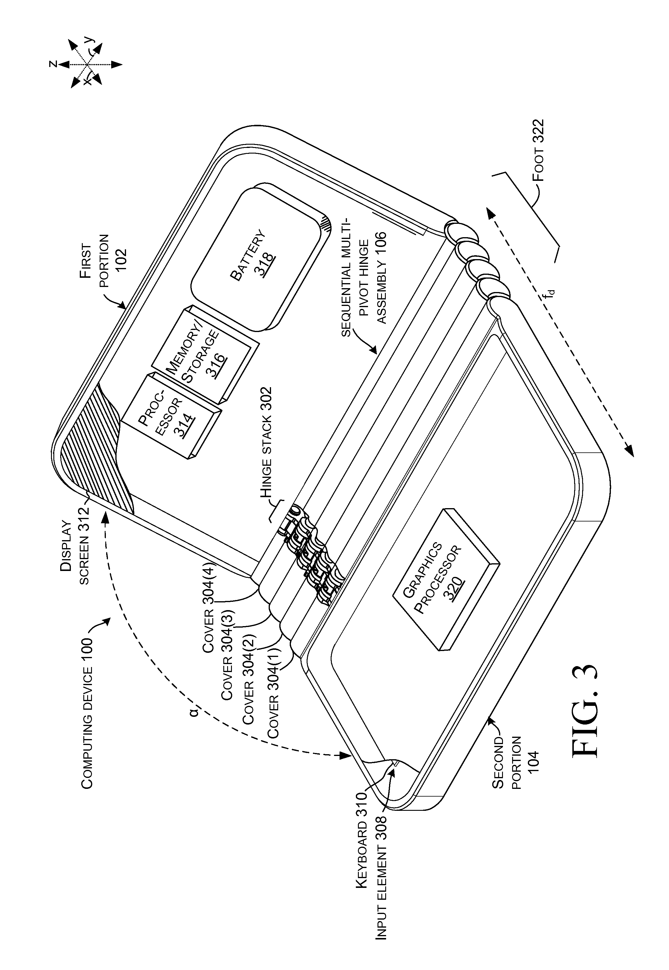
Introductory FIGS. 1-3 collectively show an example of a computing device 100. In this example, computing device 100 has first and second portions 102 and 104 that are rotatably secured together by a sequential multi-pivot hinge assembly 106. FIGS. 1-2 show the computing device in a `closed` position. FIG. 1 shows the computing device 100 from the `front` and FIG. 2 shows the computing device from the `back.` FIG. 3 is a partial cut-away perspective view that shows the computing device in an `open` or `deployed` position. In this example, in the deployed position, the first and second portions can define an obtuse angle .alpha. relative to one another, as opposed to an angle close to zero in the closed position of FIGS. 1-2. In other implementations, the deployed position can be 90 degrees or less or 180 degrees or more (e.g., a book like configuration) or up to 360 degrees. For instance, the deployed position may be somewhere in the range of 90 degrees to 180 degrees that is a comfortable viewing angle for the user.
As can be appreciated from FIG. 3, the sequential multi-pivot hinge assembly 106 can include one or more hinge stacks 302. Aspects of the sequential multi-pivot hinge assembly 106 are described in more detail below relative to FIGS. 5-10. In this example, the sequential multi-pivot hinge assembly includes rigid articulating hinge covers 304 that can obscure and/or protect the underlying elements, including the hinge stacks 302. Other implementations do not include the rigid articulating covers. Still other implementations can include a flexible hinge cover that extends between the first portion 102 and the second portion 104 over the sequential multi-pivot hinge assembly 106.
As evidenced in FIG. 3, computing device 100 can also include an input element or device 308. In this case the input device 308 is manifest as a keyboard 310. Other implementations can employ other input devices. In this example, the computing device can also include a display screen 312, such as a touch sensitive display screen. The computing device can also include a processor 314, memory/storage 316, a battery 318, and/or a video or graphics processor 320, among other components/elements. These elements can be positioned in the first portion 102 and/or second portion 104.
In this case, the second portion 104 can be configured to be positioned on a generally horizontal surface (not specifically designated), such as a table top. In the closed position of FIGS. 1-2, the first and second portions are generally parallel to one another and the horizontal surface (e.g., the first portion is juxtaposed over the second portion). In contrast, in the deployed position of FIG. 3, the first portion is rotated away from the second portion, in this case to an obtuse angle.
Note that in the closed position of FIGS. 1-2, the sequential multi-pivot hinge assembly 106 can provide a footprint f.sub.c that is compact and easy to carry. Note also, that in this implementation the progressive or sequential nature of the sequential multi-pivot hinge assembly 106 can increase or expand the footprint of the computing device when the device is transitioned from the closed or storage position of FIGS. 1-2 to the open or deployed position of FIG. 3. For example, compare the closed footprint f.sub.c to the deployed or expanded footprint f.sub.d of FIG. 3. This extended footprint feature can be especially valuable in this implementation where some or all of the electronic components, such as the display 312, processor 314, memory/storage 316, and battery 318 are positioned in the first portion 102. The extended footprint provided by the sequential multi-pivot hinge assembly 106 can increase stability of the computing device 100 and reduce the likelihood of the device tipping over backward in the deployed position from the weight of these components. Stated another way, the sequential nature of the sequential multi-pivot hinge assembly 106 can create a foot 322 in the deployed position that can help stabilize the computing device 100 and decrease tipping (e.g., maintain the center of mass over the footprint).
In the implementation shown in FIG. 3, the sequential multi-pivot hinge assembly 106 can be secured to the first and second portions 102 and 104 in a relatively permanent manner (e.g., in a manner that is not intended to be readily separable by an end use consumer). Alternatively, the sequential multi-pivot hinge assembly 106 can be secured to the first and second portions 102 and 104 in a relatively quickly attachable/detachable manner (e.g., in a manner that is intended to be readily separable by the end use consumer). One such example of this latter configuration is shown in FIG. 4.
FIG. 4 shows another computing device 100A in a view that is similar to the view of FIG. 3. In this example, the sequential multi-pivot hinge assembly 106A is configured to allow an end use consumer to easily detach either or both of the first and second portions 102 and 104 from the sequential multi-pivot hinge assembly 106A as indicated by arrow 402. In this example the sequential multi-pivot hinge assembly 106A can include a quick attach/detach assembly 404. The quick attach/detach assembly 404 may include cooperatively operating elements 406 and 408 located on the first portion 102 and the sequential multi-pivot hinge assembly 106A. Elements 406 and 408 can function to couple the first portion 102 to the sequential multi-pivot hinge assembly 106A. Similar elements can function to couple the second portion 104 to the sequential multi-pivot hinge assembly 106A.
In one example, element 406 can be manifest as a mechanical latch and element 408 can be manifest as a receiver. The latch can engage the receiver to removeably couple the first portion 102 with the sequential multi-pivot hinge assembly 106A. In another example, the elements 406 and 408 may magnetically couple to one another in a manner that can be overcome by the user to separate the first portion from the sequential multi-pivot hinge assembly 106A. Other quick attach/detach assemblies 404 are contemplated. The sequential multi-pivot hinge assembly 106A may detachably connect with either or both of the first and/or second portions. Alternatively or additionally to mechanical coupling, the quick attach/detach assembly 404 can detachably electrically couple electronic components of the first and second portions. For instance, the quick attach/detach assembly 404 may electrically couple/decouple processor 314, storage/memory 316, and/or battery 318 from the first portion 102 to the graphics processor 320 and/or keyboard 310 in the second portion 104.
Thus, the quick attach/detach assembly 404 can allow the user to be able to detach first portion 102 or second portion 104 to use either portion independently of the other. For example, first portion 102 may be operated as a stand-alone tablet device, and then may be attached to second portion 104 via sequential multi-pivot hinge assembly 106A to form a device more akin to a laptop device. A user may also be able to exchange first portion 102 or second portion 104 for application-specific devices. For example, an individual second portion may include a keyboard and/or a touchscreen. In certain scenarios, the user may attach a first touchscreen as the first portion and a second touchscreen as the second portion, and utilize the device like a book. In other scenarios, a user may attach a touchscreen as the first portion and an input device, manifest as a keyboard and trackpad, as the second portion, and utilize the device like a laptop. Other configurations and implementations are contemplated.
FIGS. 5-11 illustrate more details about the example sequential multi-pivot hinge assembly 106 including an example hinge stack 302 introduced above relative to FIG. 3. Note that due to space constraints on the drawing pages, not all elements are labeled in each FIG. and not every instance of every element is labeled, rather representative elements are labeled. FIG. 5 shows the sequential multi-pivot hinge assembly 106 in an open or deployed position similar to FIG. 3. FIG. 6 shows sequential multi-pivot hinge assembly 106 in a closed or storage position similar to FIG. 1. FIGS. 7-10 show exploded views of sequential multi-pivot hinge assembly 106 in a sequence from open in FIG. 7, partially closed in FIG. 8, further closed in FIG. 9, and fully closed in FIG. 10.
Referring collectively to FIGS. 5-10, the example hinge stack 302 can include a first portion element (e.g., interface) 502 for securing the hinge stack 302 to the first portion 102 (FIG. 1) and a second portion element (e.g., interface) 504 for securing the hinge stack 302 to the second portion 104 (FIG. 1). Hinge stack 302 can also include rotation control elements, such as rotation limiters 506, shafts 508, and cammed links 510. The hinge stack 302 can include an opening order-controlling set 512 (FIG. 7) and a separate closing order-controlling set 514 (FIG. 7). In this implementation opening order-controlling set 512 can include links 510(1)-510(5) while closing order-controlling set 514 can include links 510(6)-510(10).
In this case, the opening order-controlling set 512 can be further organized into first and second subsets 516 and 518. The first subset 516 can include links 510(1)-510(3) and the second subset 518 can include links 510(4)-510(5). The closing order-controlling set 514 can be further organized into first and second subsets 520 and 522. The first subset 520 can include links 510(6)-510(8) and the second subset 522 can include links 510(9)-510(10). Within an individual subset, links can be arranged in an end-to-end manner. This facet allows interaction between adjacent links of an individual subset as will be described below.
Links 510 can include first and second portions 524 and 526 (FIG. 7). Relative to an individual link, an individual first portion 524 can define a first passageway 528 and second portion 526 can define a second passageway 530. Individual links can also include a cam tab (e.g., tab) 532 and a cam tab engagement surface (e.g., engagement surface) 534. In the illustrated configuration, the links 510 can be thought of as approximating a figure-eight shape with the tab 532 on the first portion 524 and the engagement surface 534 on the second portion 526.
Note further, that the links 510 of the opening order-controlling set 512 can be different from the links of the closing order-controlling set 514. For instance, relative to an individual link, in the illustrated closing order-controlling set 514, the engagement surface 534 is generally opposite (e.g. about 180 degrees) from the tab 532. In contrast, in the links of the opening order-controlling set 512, the tab 532 is offset from the engagement surface (e.g., a line passing through the center of the first and second passageways 528 and 530 does not pass through a center of the tab 532 and/or the engagement surface 534).
Relative to an individual link set, such as opening order-controlling set 512, links of the first subset 516 can be offset one hinge axis from links of the second subset 518 so that an individual shaft 508 passes through first passageway 528 of an individual link in the first subset and second passageway 530 of an individual link in the second subset. For instance, shaft 508(4) passes through first passageway 528 of link 510(3) from the first subset 516 and second passageway 530 of link 510(5) of the second subset 518. Stated another way, within an individual link set, links can be offset by one hinge axis relative to the first subset and the second subset.
Note that in this implementation, the shafts 508 do not have a circular profile when viewed transverse their long axis (e.g., when viewed along the xz reference plane). Instead, in this case, the shafts have a profile that approximates a capital "D". The links' first passageway 528 and second passageway 830 both have a circular profile so that the shaft can turn freely within the passageways. In contrast, the rotation limiters 506 can include a first portion 536 and a second portion 538 (FIG. 7, relative to rotation limiter 506(4)). The first portion 536 can define a first passageway 540 and the second portion 538 can define a second passageway 542 (FIG. 7, relative to rotation limiter 506(4)). The rotation limiters' first passageway 540 can have a D shaped profile (e.g., the shape of the shaft is keyed into a fixed orientation with the first portion 536). This configuration can allow the second portion to rotate around the keyed shaft while preventing the first portion from rotating around the keyed shaft.
Other keyed shaft profiles can be utilized that cause the keyed shaft to be non-rotatable relative to individual passageways and rotatable relative to other individual passageways. For instance, a star shaped profile could be utilized where the first portion's passageway 540 matches the star profile and the second portion's passageway 542 is circular with a diameter defined by the outer points of the star. From a functional standpoint, the first portion 536 and the second portion 538 can define the angle of rotation b around an individual shaft (e.g., hinge axis, pivot axis, or axis of rotation) (see FIG. 7).
As mentioned above, the closing order-controlling set 514 can control the order of rotation around individual shafts 508. For instance, starting at the open position of FIG. 7, the user can apply a closing force f.sub.c on the first portion element 502. The closing force can cause counter-clockwise rotation around shaft 508(1). This movement turns tab 532 of link 510(6) away from engagement surface 534 of link 510(7) (compare FIG. 7 to FIG. 8). Rotation can continue through a range of degrees of rotation (e.g., angle b) as defined by the rotation limiter 506(1) associated with shaft 508(1). During this initial phase rotation around the other shafts 508(2)-508(4) is collectively blocked by the inter-relationships of the tabs and engagement surfaces of the remaining links 510(7)-510(10) of the closing order controlling set 514.
Once rotation is completed around shaft 508(1) (e.g., tab 532 of link 510(6) disengages from engagement surface 534 of link 510(7), see FIG. 8), the closing force can begin rotation around shaft 508(2) while the first portion element 502 (and shaft 508(1)) move in the negative x direction. This counter-clockwise rotation around shaft 508(2) can rotate tab 532 of link 510(9) away from engagement surface 534 of link 510(10) (compare FIG. 7, FIG. 8, and FIG. 9). This process can be serially repeated for shaft 508(3). For instance, in relation to FIG. 8, rotation around shaft 508(2) has already been completed and rotation around shaft 508(3) is possible because cam tab 532 of link 510(9) has disengaged from engagement surface 534 of link 510(10). Rotation around shaft 508(4) is still not possible because of interaction between link 510(7) and link 510(8). However, at the position of FIG. 9, rotation around shaft 508(4) can commence as rotation around shaft 508(3) is already complete thereby disengaging the cam tab (not specifically designated) of link 510(7) from link 510(8).
FIG. 11 is an intermediate position similar to FIG. 9 but with the opening order-controlling set 512 in the foreground rather than the closing order-controlling set 514 of FIG. 9. If the user applies an opening force f.sub.o, rotation can commence around shaft 508(3). Rotation around shaft 508(3) clears cam tab 532 of link 501(5) from engagement surface 534 of link 510(4) and allows rotation around shaft 508(3). Similarly, rotation around shaft 508(2) is blocked by engagement between link 510(5) and link 510(4) and rotation around shaft 508(1) is blocked by engagement of link 510(2) with link 510(1). The rotation process can be repeated sequentially along the individual shafts 508.
Viewed from one perspective, in some implementations if the tab and engagement surface on two engaged links are both concentric to a given axis of rotation, then the links can rotate with respect to one another. If they do not share a common axis of rotation and their cam tab and engagement surface are engaged, then the links are locked with respect to each other as rotation would cause the tab in one link to crash into the engagement surface of the other link.
Example Methods
Various methods of manufacture, assembly, and use for sequential multi-pivot hinge assemblies are contemplated beyond those shown above relative to FIGS. 1-11.
Additional Examples
Various examples are described above. Additional examples are described below. One example is manifest as a first portion and a second portion. This example also includes a sequential multi-pivot hinge assembly rotatably securing the first portion and the second portion from a storage position where the first portion is juxtaposed over the second portion to a deployed position where the first portion is oriented at an obtuse angle relative to the first portion. The sequential multi-pivot hinge assembly can include a first set of cammed links to control an order of rotation around individual hinge axes when the first portion and second portion are being rotated from the storage position to the deployed position and a separate second set of cammed links to control the order of rotation from the deployed position to the storage position.
Any combination of the above and/or below examples where the first set of cammed links comprises a first subset of links that are arranged end-to end with one another and a second subset of links that are arranged end-to-end with one another. The first subset of links are offset one hinge axis from the second subset of links.
Any combination of the above and/or below examples where individual links have first and second regions. Individual links of the first set of links are arranged in an end-to-end manner so that the first region of a first individual link interacts with the second region of a second individual link.
Any combination of the above and/or below examples where the individual links comprise a tab on the first region and an engagement surface on the second region, and wherein interaction of the tab of a first individual link and the engagement surface of an adjacent individual link controls rotation around an individual hinge axis passing through the individual link.
Any combination of the above and/or below examples where the sequential multi-pivot hinge assembly further comprises hinge shafts that define the hinge axes.
Any combination of the above and/or below examples where the hinge shafts have a circular profile when viewed transverse an axis of rotation or wherein the shaft is not circular.
Any combination of the above and/or below examples further including rotation control elements that define an angle of rotation around an individual axis of rotation.
Any combination of the above and/or below examples where the rotation control elements comprise a first portion that is configured to rotate around an individual hinge shaft and a second portion that is non-rotatably secured to the individual hinge shaft.
Any combination of the above and/or below examples where the sequential multi-pivot hinge assembly is configured to create a larger footprint of the computing device in the deployed position than in the storage position.
Any combination of the above and/or below examples where the sequential multi-pivot hinge assembly is visible in both the storage position and the deployed position.
Any combination of the above and/or below examples where the first portion includes a touchscreen and the second portion includes a keyboard or a touchscreen.
Any combination of the above and/or below examples where the hinge cover comprises multiple rigid hinge covers or wherein the hinge cover comprises a flexible hinge cover that extends from the first portion to the second portion.
Any combination of the above and/or below examples where the deployed position is about 90 degrees to about 360 degrees from the storage position
Another example is manifest as a first portion and a second portion. The example can include a sequential multi-pivot hinge assembly rotatably securing the first portion and the second portion and including a first set of links configured to control a relative order of rotation around individual axes of rotation of the sequential multi-pivot hinge assembly when the first and second portions are being rotated away from one another and a second different set of links configured to control the relative order of rotation around the individual axes of rotation of the sequential multi-pivot hinge assembly when the first and second portions are being rotated toward one another.
Any combination of the above and/or below examples where at least some of the links are cammed links comprising a cam tab and a cam engagement surface.
Any combination of the above and/or below examples where all of the cammed links of the first set have a same geometric shape as the cammed links of the second set or wherein the cammed links of the first set have a different geometric shape as the cammed links of the second set.
Any combination of the above and/or below examples where the cammed links have a same geometric shape or wherein individual cammed links have different geometric shapes from one another.
Any combination of the above and/or below examples where the second portion defines a footprint of the computing device when the first portion is juxtaposed over the second portion in a storage position and when the first portion is rotated away from the second portion the sequential multi-pivot hinge assembly expands the footprint.
Any combination of the above and/or below examples further including electronic components positioned in the first portion and wherein a center of mass of the computing device is located above the expanded footprint.
Another example is manifest as a hinge having a first interface and a second interface. The example can include a sequential multi-pivot hinge assembly rotatably securing the first interface and the second interface and including a first set of elements to control rotation around individual axes starting proximate to the second interface when rotating the first and second interfaces apart and a second set of elements to control rotation starting proximate to the first interface when moving the first and second interfaces toward one another.
Any combination of the above and/or below examples where the first interface includes an electrical connector and a mechanical latch.
CONCLUSION
Although techniques, methods, devices, systems, etc., pertaining to sequential multi-pivot hinge assemblies are described in language specific to structural features and/or methodological acts, it is to be understood that the subject matter defined in the appended claims is not necessarily limited to the specific features or acts described. Rather, the specific features and acts are disclosed as exemplary forms of implementing the claimed methods, devices, systems, etc.
* * * * *
References
-
shop.stormflame.com/finger-protecta-142-p.asp
-
fingersafe.com
-
alibaba.com/product-detail/Laptop-back-covers-shell-For-Dell_1628979107.html
-
presentingbinders.co.uk/Polyprop_Boxes_Accessories.html
-
catalog.monroehinge.com/category/bi-fold-hinges
-
-
irp.co.za/wp-content/assets/LFC002-7.5-Straight-Running-Double-Hinge-Chain.pdf
-
kozsusanidesign.com/samet-softcover-hinge-wins-the-innovation-award-2013
-
papadopoulos-bros.gr/en/proionta/erpystries-metaforikes-tainies/erpystries/plastikes/eutheias/monou-kai-diplou-mentese-typou-lbp-820-821-lbp
-
ultraplastindia.com/stainless-steel-slat-chains.html
-
amazon.com/System-Plast-Acetal-Straight-Running/dp/B00MJXUDIA
-
websystem.gismo.se/Gismo/files/1029/2.mph%2001%20introduktion.pdf
-
mashable.com/2012/07/30/laptop-feet
-
youtube.com/watch?v=lhEczMi4nsw
-
hingedummy.info/specialpurposepage2.htm
-
blog.parts-people.com/2015/03/03/microsoft-helps-hp-design-ne-convertible-spectre-x360
D00000
D00001
D00002
D00003
D00004
D00005
D00006
D00007
D00008
D00009
D00010
XML
uspto.report is an independent third-party trademark research tool that is not affiliated, endorsed, or sponsored by the United States Patent and Trademark Office (USPTO) or any other governmental organization. The information provided by uspto.report is based on publicly available data at the time of writing and is intended for informational purposes only.
While we strive to provide accurate and up-to-date information, we do not guarantee the accuracy, completeness, reliability, or suitability of the information displayed on this site. The use of this site is at your own risk. Any reliance you place on such information is therefore strictly at your own risk.
All official trademark data, including owner information, should be verified by visiting the official USPTO website at www.uspto.gov. This site is not intended to replace professional legal advice and should not be used as a substitute for consulting with a legal professional who is knowledgeable about trademark law.