Water collection system for a pickup truck
Pena Casimiro , et al. J
U.S. patent number 10,173,618 [Application Number 15/605,530] was granted by the patent office on 2019-01-08 for water collection system for a pickup truck. This patent grant is currently assigned to Ford Global Technologies, LLC. The grantee listed for this patent is Ford Global Technologies, LLC. Invention is credited to Jose Humberto Gutierrez, Gabriel Horta, Norberto Mondragon, Jesus Alejandro Pena Casimiro, Juan Pablo Rios Rendon.


| United States Patent | 10,173,618 |
| Pena Casimiro , et al. | January 8, 2019 |
Water collection system for a pickup truck
Abstract
A pickup truck including a truck bed, a truck box, a storage tank, and a water filtration system is provided. The truck box is mounted to the truck bed and defines a cavity. The storage tank has a valve arranged to control release of liquid received within the cavity into the storage tank. The water filtration system is disposed between, and in fluid communication with, the cavity and storage tank. Walls of the storage tank may be defined by a bumper. The water filtration system may include a strainer at a pass-through open to the cavity and a filter downstream of the pass-through. An air relief valve may be open to the storage tank. The storage tank may be mounted at a location on the truck adjacent a rear bumper of the truck.
| Inventors: | Pena Casimiro; Jesus Alejandro (Naucalpan, MX), Gutierrez; Jose Humberto (Naucalpan de Juarez, MX), Rios Rendon; Juan Pablo (Mexico City, MX), Horta; Gabriel (Estado de Mexico, MX), Mondragon; Norberto (Tiahuac, MX) | ||||||||||
|---|---|---|---|---|---|---|---|---|---|---|---|
| Applicant: |
|
||||||||||
| Assignee: | Ford Global Technologies, LLC
(Dearborn, MI) |
||||||||||
| Family ID: | 58773677 | ||||||||||
| Appl. No.: | 15/605,530 | ||||||||||
| Filed: | May 25, 2017 |
Prior Publication Data
| Document Identifier | Publication Date | |
|---|---|---|
| US 20170259768 A1 | Sep 14, 2017 | |
Related U.S. Patent Documents
| Application Number | Filing Date | Patent Number | Issue Date | ||
|---|---|---|---|---|---|
| 14967782 | Dec 14, 2015 | 9701266 | |||
| Current U.S. Class: | 1/1 |
| Current CPC Class: | B60R 19/20 (20130101); B62D 33/02 (20130101); B60R 13/07 (20130101) |
| Current International Class: | B60J 7/00 (20060101); B60R 19/20 (20060101); B62D 33/02 (20060101); B60R 13/07 (20060101) |
| Field of Search: | ;296/187.11 |
References Cited [Referenced By]
U.S. Patent Documents
| 3501170 | March 1970 | Da Valle |
| 3881768 | May 1975 | Nix |
| 4613183 | September 1986 | Kesling |
| 4674782 | June 1987 | Helber |
| 4893856 | January 1990 | Council |
| 4896910 | January 1990 | Carter |
| 4944612 | July 1990 | Abstetar |
| 4958876 | September 1990 | Diaco |
| 4961604 | October 1990 | Kisner |
| 5016932 | May 1991 | Carter |
| 5135274 | August 1992 | Dodd |
| 5221119 | June 1993 | Emery |
| 5288124 | February 1994 | Ward |
| 5364142 | November 1994 | Coiner |
| 5685593 | November 1997 | O'Connor |
| 5823585 | October 1998 | Tanguay |
| 5988723 | November 1999 | Adkins |
| 6015177 | January 2000 | Tijerina |
| 6089478 | July 2000 | Truan |
| 6234559 | May 2001 | Block |
| 6598914 | July 2003 | Dixon |
| 7607677 | October 2009 | Bosak |
| 2009/0096239 | April 2009 | Martin |
| 2012/0043773 | February 2012 | Lucas |
| 2013/0087591 | April 2013 | Cha |
| 2013/0206266 | August 2013 | Stenhouse |
| 201506306 | Jun 2010 | CN | |||
| 201863807 | Jun 2011 | CN | |||
| 102182224 | Sep 2011 | CN | |||
| 202519738 | Nov 2012 | CN | |||
| 2786885 | Oct 2014 | EP | |||
Attorney, Agent or Firm: Rogers; Jason Brooks Kushman P.C.
Parent Case Text
CROSS-REFERENCE TO RELATED APPLICATION
This application is a divisional of U.S. application Ser. No. 14/967,782, filed Dec. 14, 2015, now U.S. Pat. No. 9,701,266, the disclosure of which is incorporated in its entirety by reference herein.
Claims
What is claimed is:
1. A pickup truck comprising: a truck bed; a truck box mounted to the truck bed and defining a cavity; a storage tank having a valve arranged to control release of liquid received within the cavity into the storage tank; and a water filtration system disposed between, and in fluid communication with, the cavity and storage tank.
2. The pickup truck of claim 1, wherein walls of the storage tank are defined by a bumper.
3. The pickup truck of claim 1, wherein the water filtration system includes a strainer at a pass-through open to the cavity and a filter downstream of the pass-through.
4. The pickup truck of claim 1 further comprising an air relief valve open to the storage tank.
5. The pickup truck of claim 1, wherein the storage tank is mounted at a location on the truck adjacent a rear bumper of the truck.
6. The pickup truck of claim 1, wherein the storage tank is arranged with the truck bed such that water stored within the storage tank dissipates energy from a rear impact with the truck.
Description
TECHNICAL FIELD
The present disclosure relates to pickup truck assemblies and systems to collect liquids such as water.
BACKGROUND
Pickup trucks are motor vehicles with a front passenger area, often referred to as a cab, and an open top rear cargo area, often referred to as a box. The box usually has a substantially flat bed from which two side body panels and a forward interconnecting header extend upwardly therefrom. Pickup trucks may also employ a bottom hinged door, commonly referred to as a tailgate, hinged at the rear edge of the bed and closable to provide a fourth wall for the cargo area. Cabs and boxes may be separate assemblies or part of the same unibody structure. Pickup trucks are popular largely because the box allows them to be utilized in many different ways, including carrying a variety of types of cargo and towing various types of trailers.
SUMMARY
A pickup truck includes a truck bed, a truck box, a storage tank, and a water filtration system. The truck box is mounted to the truck bed and defines a cavity. The storage tank has a valve arranged to control release of liquid received within the cavity into the storage tank. The water filtration system is disposed between, and in fluid communication with, the cavity and storage tank. Walls of the storage tank may be defined by a bumper. The water filtration system may include a strainer at a pass-through open to the cavity and a filter downstream of the pass-through. An air relief valve may be open to the storage tank. The storage tank may be mounted at a location on the truck adjacent a rear bumper of the truck. The storage tank may be arranged with the truck bed such that water stored within the storage tank dissipates energy from a rear impact with the truck.
BRIEF DESCRIPTION OF THE DRAWINGS
FIG. 1 is a rear perspective view of a vehicle.
FIG. 2 is a side view of a vehicle with an overlaid illustrative portion showing a portion of a water collection system.
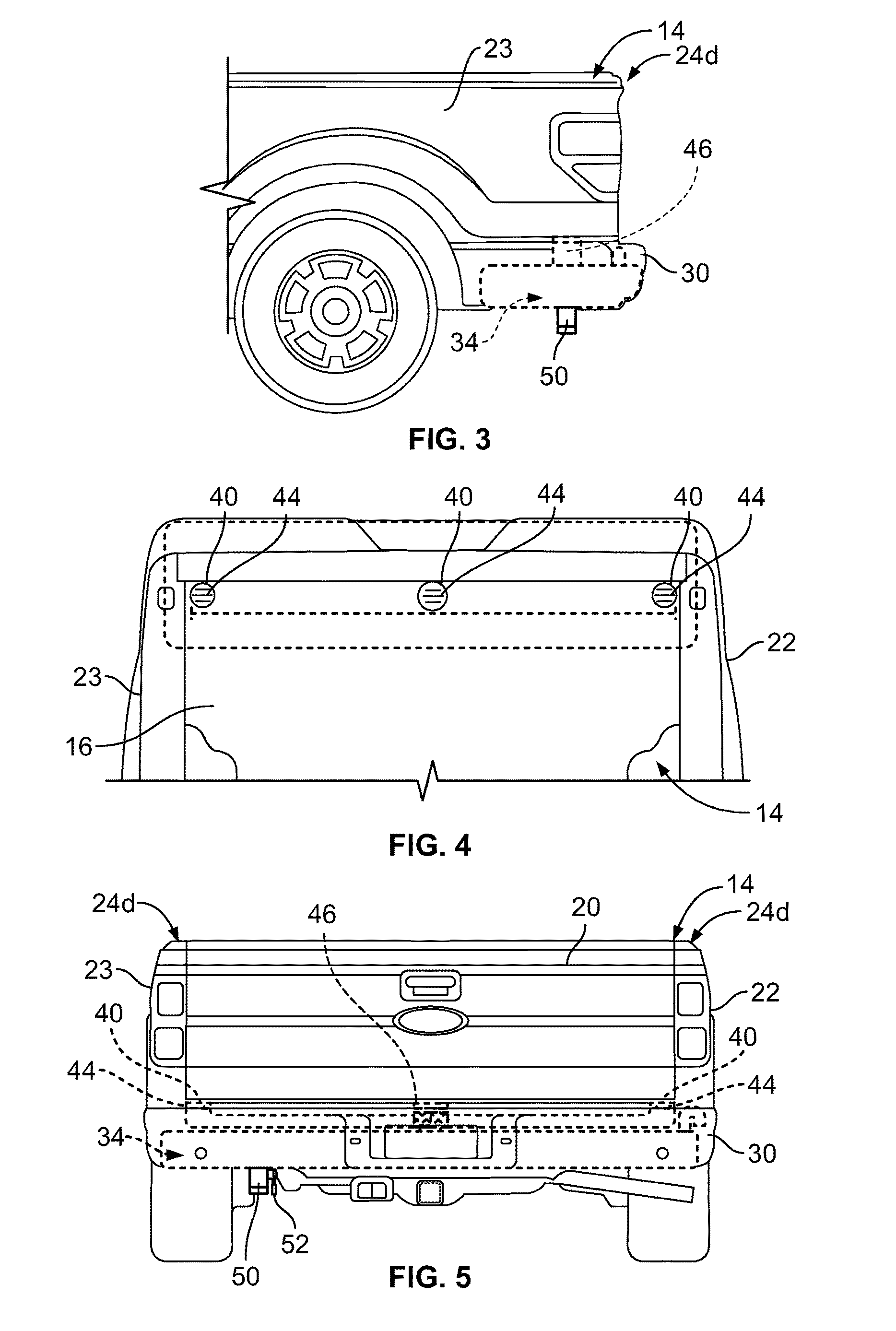
FIG. 3 is a partial side view of the vehicle of FIG. 2.
FIG. 4 is a partial rear view of the vehicle of FIG. 2.
FIG. 5 is a partial top view of the vehicle of FIG. 2.
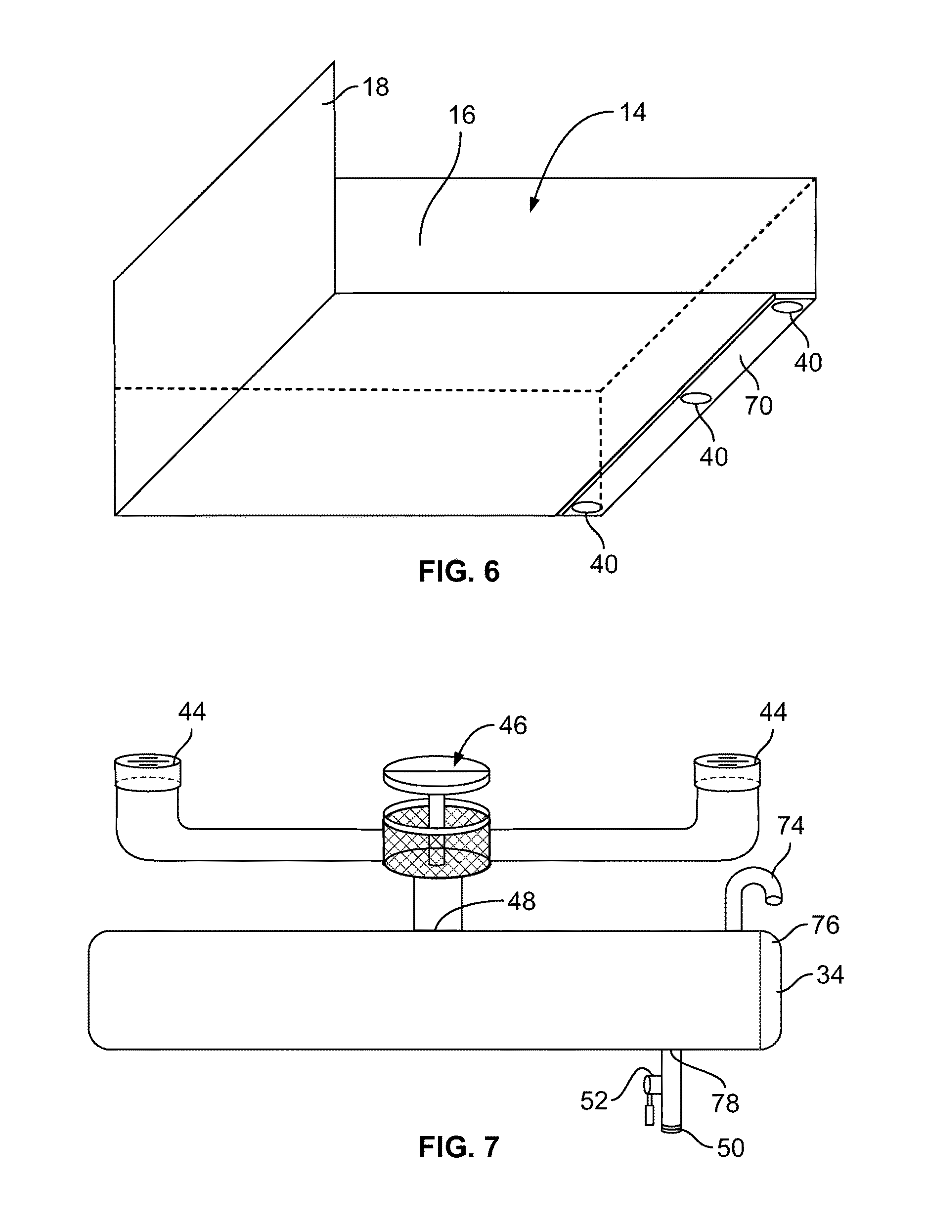
FIG. 6 is a schematic view of an example of a pickup truck box and a portion of a water collection system.
FIG. 7 is a schematic view of an example of a portion of a water collection system for a pickup truck box.
DETAILED DESCRIPTION
Embodiments of the present disclosure are described herein. It is to be understood, however, that the disclosed embodiments are merely examples and other embodiments may take various and alternative forms. The figures are not necessarily to scale; some features could be exaggerated or minimized to show details of particular components. Therefore, specific structural and functional details disclosed herein are not to be interpreted as limiting, but merely as a representative basis for teaching one skilled in the art to variously employ the present disclosure. As those of ordinary skill in the art will understand, various features illustrated and described with reference to any one of the figures may be combined with features illustrated in one or more other figures to produce embodiments that are not explicitly illustrated or described. The combinations of features illustrated provide representative embodiments for typical applications. Various combinations and modifications of the features consistent with the teachings of this disclosure, however, could be desired for particular applications or implementations.
Referring to FIGS. 1 and 2, an example of a vehicle 10 is shown which may include a cabin 12 and a truck box 14 supported by a vehicle chassis (not shown). The vehicle 10 may be, for example, a pickup truck. The truck box 14 includes a bed 16 having a forward end adjacent to the cabin 12 and a rear end opposite the forward end. The bed 16 supports a header 18 at the forward end and a tailgate 20 at the rear end. The tailgate 20 is mounted to the bed 16 for rotation. The bed 16 may also support a first body side panel 22 and a second body side panel 23. In this example, the vehicle 10 may include an A-pillar region 24a, a B-pillar region 24b, a C-pillar region 24c, and a D-pillar region 24d. The illustrated vehicle 10 is a four-door configuration; however other configurations, such as a two-door configuration, may be adopted to incorporate the disclosed concepts. Alternate configurations may include different pillar region references than as described for the vehicle 10. The first body side panel 22 and the second body side panel 23 may be secured to the header 18 at respective regions referred to as forward box pillar regions of the truck box 14 or the C-pillar regions 24c herein. The first body side panel 22 and the second body side panel 23 may each include fascia portions. The tailgate 20 rotates from at least an open position to a closed position. In the closed position as shown in FIGS. 1 and 2, each lateral end of the tailgate 20 may be removably attached to the first body side panel 22 and the second body side panel 23 at respective regions referred to as rear box pillar regions or the D-pillar regions 24d herein. A bumper 30 is mounted to the frame of the vehicle 10 and disposed at a rear of the vehicle 10.
A cavity may be defined by the truck box 14 and/or the bed 16. For example, the header 18, the tailgate 20, the first body side panel 22, the second body side panel 23, and the bed 16 may define a cavity therebetween. The cavity may me open and may receive water under certain conditions, such as rain water.
Referring additionally to FIGS. 3 through 4, an example of a water collection system is shown. The water collection system may include the cavity defined by the truck box 14 and/or the bed 16. The water collection system may be mounted to a vehicle, such as the vehicle 10, and include a reservoir, container or tank. For example, the bumper 30 may define a reservoir 34 therein. Alternatively, a container may be mounted to the vehicle 10 adjacent the bumper 30. One or more ports 40 provide fluid communication between the cavity and the reservoir 34. For example, the bed 16 may define ports in substantial registration with other ports defined by the bumper 30 such that water may pass from the cavity to the reservoir 34. Water stored within the reservoir 34 may also assist in dissipating energy when the vehicle 10 receives a rear impact. For example, the reservoir 34 may be arranged with the truck bed 16 such that water stored within the reservoir 34 is at a location on the vehicle 10 to dissipate energy from a rear impact with the vehicle 10.
The water collection system may also include a filtration system and a distribution system. For example, the filtration system may include a strainer 44 and a filter 46. The strainer 44 may be mounted at one of the one or more ports 40 to assist in preventing debris from entering the reservoir 34. It is contemplated that additional components, such as a second strainer may be used with the system to assist in preventing debris from entering the reservoir. For example, the second strainer may be structured to prevent small debris, such as insects, from entering the reservoir 34. The filter 46 may be downstream of the one or more ports 40 and assist in filtering water passing therethrough. The filter 46 may be accessible for cleaning and replacement purposes. For example, one of the one or more ports 40 may be open to the filter 46. The filtration system may operate to cleanse water prior to entering to the reservoir 34 via a port 48.
The distribution system may be in fluid communication with the reservoir 34 and the filtration system and may include an outlet 50 and a valve control 52. The valve control 52 may selectively control output of liquid from the reservoir 34 via the outlet 50. For example, water stored within the reservoir 34 may be used to wash the vehicle 10, to water a garden, or other similar applications.
FIGS. 6 and 7 show a schematic example of a truck box, such as truck box 14, and a water collection system as described above. In this example, the truck bed 16 is shown defining a gutter 70. The gutter 70 may be formed to influence a flow of liquid toward the one or more ports 40. An air relief pipe 74 may be open to the reservoir 34 and include a screen to prevent entrance therein. The air relief pipe 74 may assist in preventing undesirable pressure within the reservoir 34. A sensor 76 may be disposed within the reservoir 34 to identify an amount of liquid therein. The sensor 76 may, for example, be in communication with a controller (not shown) and indicia located in, for example, the vehicle cabin 12 to monitor and output a signal indicating a water level within the reservoir.
Water may enter the cavity of the truck box 14 and flow to the one or more ports 40. In another example, the bed 16 may define gutters (not shown) extending along a base of the first body side panel 22 or the second body side panel 23. The one or more ports 40 may be in substantial registration with the respective strainer 44 and/or the filter 46. Water may flow through the strainers 44 and filter 46 enroute to the reservoir 34 via the port 48. Water may then be discharged through a port 78 and the outlet 50 as selectively controlled by the valve control 52.
The words used in the specification are words of description rather than limitation, and it is understood that various changes may be made without departing from the spirit and scope of the disclosure. As previously described, the features of various embodiments may be combined to form further embodiments of the invention that may not be explicitly described or illustrated. While various embodiments could have been described as providing advantages or being preferred over other embodiments or prior art implementations with respect to one or more desired characteristics, those of ordinary skill in the art recognize that one or more features or characteristics may be compromised to achieve desired overall system attributes, which depend on the specific application and implementation. These attributes may include, but are not limited to cost, strength, durability, life cycle cost, marketability, appearance, packaging, size, serviceability, weight, manufacturability, ease of assembly, etc. As such, embodiments described as less desirable than other embodiments or prior art implementations with respect to one or more characteristics are not outside the scope of the disclosure and may be desirable for particular applications.
* * * * *
D00000
D00001
D00002
D00003
XML
uspto.report is an independent third-party trademark research tool that is not affiliated, endorsed, or sponsored by the United States Patent and Trademark Office (USPTO) or any other governmental organization. The information provided by uspto.report is based on publicly available data at the time of writing and is intended for informational purposes only.
While we strive to provide accurate and up-to-date information, we do not guarantee the accuracy, completeness, reliability, or suitability of the information displayed on this site. The use of this site is at your own risk. Any reliance you place on such information is therefore strictly at your own risk.
All official trademark data, including owner information, should be verified by visiting the official USPTO website at www.uspto.gov. This site is not intended to replace professional legal advice and should not be used as a substitute for consulting with a legal professional who is knowledgeable about trademark law.