Trimming apparatus
Scholz , et al. J
U.S. patent number 10,172,702 [Application Number 15/357,659] was granted by the patent office on 2019-01-08 for trimming apparatus. This patent grant is currently assigned to C. R. Bard, Inc.. The grantee listed for this patent is C. R. BARD, INC.. Invention is credited to Debra A. Bebb, Robert M. Carr, John D. McDermott, Hans Scholz.
| United States Patent | 10,172,702 |
| Scholz , et al. | January 8, 2019 |
Trimming apparatus
Abstract
A vascular graft with trim lines is described, the trim lines providing a guide for precision shaping of the cuff. The trim lines may be printed or otherwise disposed on a surface of the cuff or included on a template designed for disposition over the cuff. The trim lines may also be disposed on a side of a pocket into which the cuff is positioned for trimming. Also described is an apparatus and method for precise trimming of a vascular graft.
| Inventors: | Scholz; Hans (Berlin, DE), McDermott; John D. (Coto de Caza, CA), Carr; Robert M. (Tempe, AZ), Bebb; Debra A. (Tempe, AZ) | ||||||||||
|---|---|---|---|---|---|---|---|---|---|---|---|
| Applicant: |
|
||||||||||
| Assignee: | C. R. Bard, Inc. (Murray Hill,
NJ) |
||||||||||
| Family ID: | 37590657 | ||||||||||
| Appl. No.: | 15/357,659 | ||||||||||
| Filed: | November 21, 2016 |
Prior Publication Data
| Document Identifier | Publication Date | |
|---|---|---|
| US 20170065399 A1 | Mar 9, 2017 | |
Related U.S. Patent Documents
| Application Number | Filing Date | Patent Number | Issue Date | ||
|---|---|---|---|---|---|
| 14228995 | Mar 28, 2014 | 9532865 | |||
| 11408330 | Apr 29, 2014 | 8709069 | |||
| 60695406 | Jul 1, 2005 | ||||
| Current U.S. Class: | 1/1 |
| Current CPC Class: | A61F 2/06 (20130101); A61F 2/07 (20130101); A61F 2250/0039 (20130101); A61F 2240/005 (20130101); Y10T 83/75 (20150401) |
| Current International Class: | A61B 17/32 (20060101); A61F 2/06 (20130101); A61F 2/07 (20130101) |
| Field of Search: | ;606/167 |
References Cited [Referenced By]
U.S. Patent Documents
| 2127903 | August 1938 | Bowen |
| 3196194 | July 1965 | Ely, Jr. et al. |
| 3492994 | February 1970 | Field |
| 3683926 | August 1972 | Suzuki |
| 3713441 | January 1973 | Thomas |
| 3805301 | April 1974 | Liebig |
| 3815608 | June 1974 | Spinosa et al. |
| 3816919 | June 1974 | Portnoy |
| 3818511 | June 1974 | Goldberg et al. |
| 3825257 | July 1974 | Palmer |
| 3826257 | July 1974 | Buselmeier |
| 3853462 | December 1974 | Smith |
| 3882862 | May 1975 | Berend |
| 3945052 | March 1976 | Liebig |
| 3986828 | October 1976 | Hoffman, Jr. et al. |
| 4047252 | September 1977 | Liebig et al. |
| 4098571 | July 1978 | Miyata et al. |
| 4192312 | March 1980 | Wilson |
| 4234535 | November 1980 | Okita |
| 4279259 | July 1981 | Lee et al. |
| 4309776 | January 1982 | Berguer |
| 4313231 | February 1982 | Koyamada |
| 4321914 | March 1982 | Begovac et al. |
| 4345414 | August 1982 | Bornat et al. |
| 4354495 | October 1982 | Bodicky |
| 4366819 | January 1983 | Kaster |
| 4387516 | June 1983 | Laux |
| 4416028 | November 1983 | Eriksson et al. |
| 4441215 | April 1984 | Kaster |
| 4482516 | November 1984 | Bowman et al. |
| 4501263 | February 1985 | Harbuck |
| 4503568 | March 1985 | Madras |
| 4517687 | May 1985 | Liebig et al. |
| 4530113 | July 1985 | Matterson |
| 4561129 | December 1985 | Arpesella |
| 4601718 | July 1986 | Possis et al. |
| 4630375 | December 1986 | Spolyar |
| 4712551 | December 1987 | Rayhanabad |
| 4714421 | December 1987 | D'Agostino |
| 4728328 | March 1988 | Hughes et al. |
| 4743480 | May 1988 | Campbell et al. |
| 4807622 | February 1989 | Ohkaka et al. |
| 4816028 | March 1989 | Kapadia et al. |
| 4840940 | June 1989 | Sottiurai |
| 4872455 | October 1989 | Pinchuk et al. |
| 4883453 | November 1989 | Berry et al. |
| 4909979 | March 1990 | Possis et al. |
| 4935190 | June 1990 | Tennerstedt |
| 4944737 | July 1990 | Bloom |
| 4957508 | September 1990 | Kaneko et al. |
| 4957669 | September 1990 | Primm |
| 5042161 | August 1991 | Hodge |
| 5078735 | January 1992 | Mobin-Uddin |
| 5100422 | March 1992 | Berguer et al. |
| 5110526 | May 1992 | Hayashi et al. |
| 5156619 | October 1992 | Ehrenfeld |
| 5304340 | April 1994 | Downey |
| D348618 | July 1994 | Leslie et al. |
| 5376110 | December 1994 | Tu et al. |
| 5387236 | February 1995 | Noishiki et al. |
| 5399352 | March 1995 | Hanson |
| 5443497 | August 1995 | Venbrux |
| 5456712 | October 1995 | Maginot |
| 5456714 | October 1995 | Owen |
| 5472404 | December 1995 | Volgushev |
| 5476506 | December 1995 | Lunn |
| 5496341 | March 1996 | Sauer et al. |
| 5500014 | March 1996 | Quijano et al. |
| 5575817 | November 1996 | Martin |
| 5591203 | January 1997 | Fahy |
| 5653743 | August 1997 | Martin |
| 5683449 | November 1997 | Marcade |
| 5695504 | December 1997 | Gifford, III et al. |
| 5713859 | February 1998 | Finch, Jr. et al. |
| 5723005 | March 1998 | Herrick |
| 5752934 | May 1998 | Campbell et al. |
| 5755779 | May 1998 | Horiguchi |
| 5755780 | May 1998 | Finch, Jr. et al. |
| 5782916 | July 1998 | Pintauro et al. |
| 5814005 | September 1998 | Barra et al. |
| 5824010 | October 1998 | McDonald |
| 5827327 | October 1998 | McHaney et al. |
| 5843158 | December 1998 | Lenker et al. |
| 5843165 | December 1998 | Plaia et al. |
| 5849036 | December 1998 | Zarate |
| 5861026 | January 1999 | Harris et al. |
| 5893886 | April 1999 | Zegdi et al. |
| 5902317 | May 1999 | Kleshinski et al. |
| 5950320 | September 1999 | Dorsey |
| 5976159 | November 1999 | Heartport |
| 5989287 | November 1999 | Yang et al. |
| 6019788 | February 2000 | Butters et al. |
| 6039754 | March 2000 | Caro |
| 6048362 | April 2000 | Berg |
| 6056717 | May 2000 | Finch et al. |
| 6086553 | July 2000 | Akbik |
| 6102884 | August 2000 | Squitieri |
| 6136022 | October 2000 | Nunez et al. |
| 6187033 | February 2001 | Schmitt et al. |
| 6190590 | February 2001 | Randall et al. |
| 6193746 | February 2001 | Strecker |
| 6203735 | March 2001 | Edwin et al. |
| 6210430 | April 2001 | Solem |
| 6221101 | April 2001 | Harris et al. |
| 6273912 | August 2001 | Scholz |
| 6371981 | April 2002 | Yang et al. |
| 6436135 | August 2002 | Goldfarb |
| 6458155 | October 2002 | Van Nguyen et al. |
| 6554856 | April 2003 | Doorly et al. |
| 6582409 | June 2003 | Squitieri |
| 6585762 | July 2003 | Stanish |
| 6589278 | July 2003 | Harris et al. |
| 6613087 | September 2003 | Healy et al. |
| 6626865 | September 2003 | Prisell |
| 6626939 | September 2003 | Burnside et al. |
| 6746480 | June 2004 | Scholz et al. |
| 6767358 | July 2004 | Leonhardt et al. |
| 6821295 | November 2004 | Farrar |
| 6857196 | February 2005 | Dalrymple |
| 6858035 | February 2005 | Whayne |
| 7553316 | June 2009 | Scholz et al. |
| 8709069 | April 2014 | Scholz et al. |
| 9532865 | January 2017 | Scholz |
| 2002/0193872 | December 2002 | Trout et al. |
| 2003/0014108 | January 2003 | Lauren |
| 2003/0051362 | March 2003 | Buckman et al. |
| 2003/0182815 | October 2003 | Carlson |
| 2004/0039453 | February 2004 | Anderson et al. |
| 2004/0064181 | April 2004 | Harris et al. |
| 2004/0210302 | October 2004 | Scholz et al. |
| 2005/0055079 | March 2005 | Duran |
| 2005/0272806 | December 2005 | Falotico et al. |
| 2006/0030935 | February 2006 | Scholz et al. |
| 2006/0210816 | September 2006 | Finley |
| 2007/0005128 | January 2007 | Scholz et al. |
| 2007/0255400 | November 2007 | Parravicini et al. |
| 2010/0280598 | November 2010 | Fox |
| 2014/0208913 | July 2014 | Scholz et al. |
| 0269254 | Jun 1988 | EP | |||
| 63158052 | Jul 1988 | JP | |||
| 1995009585 | Apr 1995 | WO | |||
| 1995014442 | Jun 1995 | WO | |||
| 1995034255 | Dec 1995 | WO | |||
| 1996000103 | Jan 1996 | WO | |||
| 1997031591 | Sep 1997 | WO | |||
| 1998052495 | Nov 1998 | WO | |||
Other References
|
Advertisement for FEP-Ringed Gore-TEX Vascular Graft, 1 page, prior to Jun. 21, 1989. cited by applicant . Bard Peripheral Vascular, Inc., Venaflo Vascular Grafts Information for Use, Rev. 2, 10/104, 2004. cited by applicant . Bard Peripheral Vascular, Inc.; "Hemodynamics and Cuff Technology", 2005. cited by applicant . Batson, R.C., M.D. et al; "Linton Patch Angioplasty", Ann. Surg., pp. 684-693, vol. 199, No. 6, Jun. 1984. cited by applicant . Beard, J.D. et al, Haemodynamics of the Interposition Vein Cuff, Sr. J. Surg, vol. 73, No. 10, pp. 823-825, Oct. 1986. cited by applicant . Chester et al, "Interposition Vein Patches for Vascular Reconstruction", pp. 1-3, Feb. 1993. cited by applicant . Crawshaw et al, "Flow Disturbance at the Distal End-ta-Side Anastomosis", Arch Surg, vol. 115, pp. 1280-1284, Nov. 1980. cited by applicant . Da Silva, A.F. et al, "Stable Vortices Within Vein Cuffs Inhibit Anastomotic Myointimal Hyperplasia", Eur J Vase Sura, vol. 14, pp. 157-163, 1997. cited by applicant . Dobrin et al, "Mechanical factors predisposing to intimal hyperplasia and medial thickening in autoaenous vein arafts", Surgery, vol. 105, No. 3, pp. 393-400, Mar. 1989. cited by applicant . EP 98921634.6 filed May 15, 2008 Office Action dated May 5, 2004. cited by applicant . EP 98921634.6 filed May 15, 2008 Office Action dated Oct. 10, 2004. cited by applicant . Escobar, Francisco S. III et al, "Comparison of a New Hooded Graft With a Conventional ePTFE Graft: A Preliminary Study", Vascular Access for Hemodialysis VI, pp. 205-212, 1999. cited by applicant . Fillinger et al, "Beneficial Effects of Banding on Venous Intimal-Medial Hyperplasia in Arteriovenous Loop Grafts"; The American Journal of Surgery, vol. 158, pp. 87-94, Aug. 1989. cited by applicant . Fillinger et al, "Graft Geometry and Venous Intimal-Medial Hyperplasia in Arteriovenous Loop Grafts", Journal of Vascular Surgery, vol. 11, No. 4, pp. 556-566, Apr. 1990. cited by applicant . Fisher, R.K. et al, "Harnessing Haemodynamic Forces for the Suppression of Anastomotic Intimal Hyperplasia: the Rationale for Precuffed Grafts", Eur J Vase Endovasc Surg, vol. 21, pp. 520-528, 2001. cited by applicant . Gagne, P. J. et al, "The Effect of a Venous Anastomosis Tyrell Vein Collar on the Primary Patency of Arteriovenous Grafts in Patients Undergoing Hemodialysis", J Vase Surg, vol. 32, No. 6, pp. 1149-1154, 2000. cited by applicant . Green, R. M. et al, "Prosthetic Above-Knee Femoropopliteal Bypass Grafting: Five-Year Results of a Randomized Trial", J Vasc Surg, vol. 31, No. 3, pp. 417-425, Mar. 2000. cited by applicant . Harris, Peter et al, "Haemodynamics of Cuffed Arterial Anastomoses", Critical Ischaemia, vol. 9, No. 1, pp. 20-26, 1999. cited by applicant . How, T. V. et al, "Interposition Vein Cuff Anastomosis Alters Wall Shear Stress Distribution in the Recipient Artery", J Vasc Surg, vol. 31, No. 5, pp. 1008-1017, May 2000. cited by applicant . Impra, Inc, "Suturing Technique for Venaflo ePTFE Vascular Graft & Venaflo Graft with Carbon", 1998. cited by applicant . Impra, Inc, "Tunneling Technique for Venaflo ePTFE Vascular Graft & Venaflo Graft with Carbon", 1999. cited by applicant . Jamieson, et al, "Vascular Surgery", 5th Edition, ISBN 04 12586 304, pp. 330-340, 1994. cited by applicant . JP 2006-303732 Office Action dated Jun. 2, 2009. cited by applicant . Krueger et al, "Importance of Correct Trimming of Venaflo Grafts Proven by CFD", 4th International Congress of the Vascular Access Society, Berlin, Germany, May 25, 2005. cited by applicant . Lei, Ming et al, "Computational Design of a Bypass Graft That Minimizes Wall Shear Stress Gradients in the Region of the Distal Anastomosis", Journal of Vascular Surgery, vol. 25, No. 4, pp. 637-646, Apr. 1997. cited by applicant . Lemson, M.S. et al, "Effects of a Venous Cuff at the Venous Anastomosis of Polytetrafluoroethylene Grafts for Femodialysis Vascular Access", J Vasc Surg, vol. 32, No. 6, pp. 1155-1163, Dec. 2000. cited by applicant . Loh, A. et al, "PTFE Bypass Grafting to Isolated Popliteal Segments in Critical Limb Ischaemia", Eur J Vasc Sur, vol. 7, pp. 26-30, Jan. 1993. cited by applicant . Miller et al, "The use of the vein cuff and PTFE" In: Greenhalgh RM, ed. Vascular Surgical Techniques. An Atlas. 2nd ed. London: W.B. Saunders, 1989; 276-86. cited by applicant . Nyberg et al, "Preliminary Experience with a Cuffed ePTFE Graft for Hemodialysis Vascular Access", Asaio Journel, vol. 47, No. 4, pp. 333-337, Jul./Aug. 2001. cited by applicant . Panneton, J. M., MD., "Multicenter Randomized Prospective Trial Comparing a Pre-Cuffed Polytetrafluoroethylene Graft to a Vein Cuffed Polytetrafluoroethylene Graft for Infragenicular Arterial Bypass", Ann Vasc Sura, vol. 18, pp. 199-206, Mar. 15, 2004. cited by applicant . PCT/GB1998/001418 filed May 15, 1998 International Preliminary Examination Report dated Aug. 25, 1999. cited by applicant . PCT/GB1998/001418 filed May 15, 1998 International Search Report dated Sep. 2, 1998. cited by applicant . PCT/GB1998/001418 filed May 15, 1998 Written Opinion dated Sep. 2, 1998. cited by applicant . PCT/US2008/088312 filed Dec. 24, 2008 Search Report dated Feb. 13, 2009. cited by applicant . PCT/US2008/088312 filed Dec. 24, 2008 Written Opinion dated Feb. 13, 2009. cited by applicant . Dueen Elisabeth Hospital Berlin, "Documentation of Comparative Flow Investigations of the Conventional Anastomosis and `Venaflo II` Anastomosis by a Pulsatile Circulating Model". cited by applicant . Scholz, Hans M.D. et al, "Five Years' Experience With an Arteriovenous Patch Prosthesis as Access for Hemodialysis", Vascular Access for Hemodialysis VI, pp. 241-254, 1999. cited by applicant . Sivanesan, S. et al, "Flow Patterns in the Radiocephalic Arteriovenous Fistular: An in Intro Study", J Biomech, vol. 32, pp. 915-925, 1999. cited by applicant . Sorom, AJ. et al, "Prospective, Randomized Evaluation of a Cuffed Expanded Polytetrafluoroethylene Graft for Hemodialysis Vascular Access", Surgery, vol. 132, No. 2, Aug. 2002. cited by applicant . Stonebridge, P.A. et al, "Randomized Trial Comparing Infrainguinal Polytetrafluoroethylene Bypass Grafting With and Without Vein Interpostion Cuff at the Distal Anastomosis", J Vasc Sur, vol. 26, No. 4, pp. 543-550, Oct. 1997. cited by applicant . Taylor et al, "Improved Technique for Polytetraflouroethylene Bypass Grafting: Long-Term Results Using Anastomotic Vein Patches", The British Journal of Surgery 1992, vol. 79, pp. 348-354, Apr. 4, 1992. cited by applicant . Tyrrell, M.R. et al, "New Prosthetic Venous Collar Anastomotic Technique: Combining the Best of Other Procedures", British J Sur, vol. 78, pp. 1016-1017, Aug. 1991. cited by applicant . U.S. Appl. No. 10/603,952, filed Jun. 25, 2003 Final Office Action dated Sep. 18, 2014. cited by applicant . U.S. Appl. No. 10/603,952, filed Jun. 25, 2003 Non-Final Office Action dated May 10, 2013. cited by applicant . U.S. Appl. No. 10/603,952, filed Jun. 25, 2003 Advisory Action dated Dec. 24, 2013. cited by applicant . U.S. Appl. No. 10/603,952, filed Jun. 25, 2003 Advisory Action dated Dec. 3, 2010. cited by applicant . U.S. Appl. No. 10/603,952, filed Jun. 25, 2003 Advisory Action dated Jan. 6, 2015. cited by applicant . U.S. Appl. No. 10/603,952, filed Jun. 25, 2003 Advisory Action dated Jun. 8, 2006. cited by applicant . U.S. Appl. No. 10/603,952, filed Jun. 25, 2003 Advisory Action dated Sep. 4, 2007. cited by applicant . U.S. Appl. No. 10/603,952, filed Jun. 25, 2003 Decision on Appeal dated Jan. 16, 2013. cited by applicant . U.S. Appl. No. 10/603,952, filed Jun. 25, 2003 Final Office Action dated Apr. 16, 2007. cited by applicant . U.S. Appl. No. 10/603,952, filed Jun. 25, 2003 Final Office Action dated Feb. 17, 2006. cited by applicant . U.S. Appl. No. 10/603,952, filed Jun. 25, 2003 Final Office Action dated Oct. 16, 2013. cited by applicant . U.S. Appl. No. 10/603,952, filed Jun. 25, 2003 Final Office Action dated Oct. 18, 2004. cited by applicant . U.S. Appl. No. 10/603,952, filed Jun. 25, 2003 Final Office Action dated Sep. 16, 2010. cited by applicant . U.S. Appl. No. 10/603,952, filed Jun. 25, 2003 Non-Final Office Action dated Apr. 22, 2004. cited by applicant . U.S. Appl. No. 10/603,952, filed Jun. 25, 2003 Non-Final Office Action dated Apr. 6, 2010. cited by applicant . U.S. Appl. No. 10/603,952, filed Jun. 25, 2003 Non-Final Office Action dated Aug. 31, 2006. cited by applicant . U.S. Appl. No. 10/603,952, filed Jun. 25, 2003 Non-Final Office Action dated Feb. 26, 2014. cited by applicant . U.S. Appl. No. 10/603,952, filed Jun. 25, 2003 Non-Final Office Action dated Mar. 4, 2005. cited by applicant . U.S. Appl. No. 10/603,952, filed Jun. 25, 2003 Non-Final Office Action dated Oct. 15, 2009. cited by applicant . U.S. Appl. No. 10/842,582, filed May 10, 2004 Final Office Action dated Dec. 31, 2008. cited by applicant . U.S. Appl. No. 10/842,582, filed May 10, 2004 Non-Final Office Action dated Jul. 5, 2007. cited by applicant . U.S. Appl. No. 10/842,582, filed May 10, 2004 Non-Final Office Action dated Nov. 16, 2007. cited by applicant . U.S. Appl. No. 11/239,416, filed Sep. 30, 2005 Advisory Action dated Feb. 13, 2014. cited by applicant . U.S. Appl. No. 11/239,416, filed Sep. 30, 2005 Final Office Action dated Dec. 5, 2011. cited by applicant . U.S. Appl. No. 11/239,416, filed Sep. 30, 2005 Final Office Action dated Mar. 25, 2010. cited by applicant . U.S. Appl. No. 11/239,416, filed Sep. 30, 2005 Final Office Action dated Oct. 24, 2014. cited by applicant . U.S. Appl. No. 11/239,416, filed Sep. 30, 2005 Non-Final Office Action dated Apr. 11, 2014. cited by applicant . U.S. Appl. No. 11/239,416, filed Sep. 30, 2005 Non-Final Office Action dated Jun. 7, 2013. cited by applicant . U.S. Appl. No. 11/239,416, filed Sep. 30, 2005 Non-Final Office Action dated Sep. 18, 2009. cited by applicant . U.S. Appl. No. 11/408,330, filed Apr. 21, 2006 Advisory Action dated Nov. 23, 2010. cited by applicant . U.S. Appl. No. 11/408,330, filed Apr. 21, 2006 Final Office Action dated Oct. 17, 2012. cited by applicant . U.S. Appl. No. 11/408,330, filed Apr. 21, 2006 Final Office Action dated Sep. 14, 2010. cited by applicant . U.S. Appl. No. 11/408,330, filed Apr. 21, 2006 Non-Final Office Action dated Jun. 28, 2013. cited by applicant . U.S. Appl. No. 11/408,330, filed Apr. 21, 2006 Non-Final Office Action dated Mar. 24, 2010. cited by applicant . U.S. Appl. No. 11/408,330, filed Apr. 21, 2006 Non-Final Office Action dated Mar. 29, 2012. cited by applicant . U.S. Appl. No. 11/408,330, filed Apr. 21, 2006 Non-Final Office Action dated Sep. 28, 201t. cited by applicant . U.S. Appl. No. 12/810,822, filed Jun. 25, 2010 Final Office Action dated Sep. 28, 2012. cited by applicant . U.S. Appl. No. 12/810,822, filed Jun. 25, 2010 Non-Final Office Action dated Apr. 13, 2012. cited by applicant . Wells et al, "Effect of carotid artery geometry on the magnitude and distribution of wall shear stress gradients", Journal of Vascular Surgery, vol. 23, No. 4, pp. 667-678, Apr. 1996. cited by applicant . Wolfe, John H. N., "Polytetrafiuoroethylene (PTFE) Femorodistal Bypass", Rob & Smith's Operative Surgery/Vascular Surgery, Fifth Edition, pp. 330-340, Sep. 4, 1998. cited by applicant. |
Primary Examiner: Tyson; Melanie
Attorney, Agent or Firm: Rutan & Tucker, LLP
Parent Case Text
PRIORITY
This application is a division of U.S. patent application Ser. No. 14/228,995, filed Mar. 28, 2014, now U.S. Pat. No. 9,532,865, which is a division of U.S. patent application Ser. No. 11/408,330, filed Apr. 21, 2006, now U.S. Pat. No. 8,709,069, which claims the benefit under 35 U.S.C. .sctn. 119(e) to U.S. Provisional Application No. 60/695,406, filed Jul. 1, 2005, each of which is incorporated by reference into this application as if fully set forth herein.
Claims
What is claimed is:
1. A kit comprising: a vascular graft comprising: a tube and a cuff extending from the tube, wherein the cuff has an open end defining a flared skirt with an outer peripheral edge; and an apparatus for trimming the vascular graft comprising: a base that receives a portion of the flared skirt; and a template that projects a first guide defining a trimmed peripheral edge onto the flared skirt.
2. The kit of claim 1, wherein the vascular graft further comprises a first marking disposed on a surface of the cuff providing an indication for trimming the cuff.
3. The kit of claim 2, wherein the vascular graft further comprises an alignment guide disposed on a surface of the tube and the cuff.
4. The kit of claim 3, wherein the cuff is offset from a longitudinal axis of the tube such that a first focal point of the cuff is positioned a greater distance from the longitudinal axis than a second focal point of the cuff.
5. The kit of claim 4, wherein the cuff includes a toe section adjacent the first focal point and a heel section adjacent the second focal point.
6. The kit of claim 5, wherein the template is pivotally mounted with respect to the base.
7. The kit of claim 3, wherein the cuff is integral and continuous with the tube.
8. The kit of claim 7, wherein the template comprises a first guide to a first trimmed peripheral edge of the flared skirt and a second guide to a second trimmed peripheral edge of the flared skirt.
9. The kit of claim 8, wherein the template further comprises a register aligning the base to the vascular graft.
10. The kit of claim 9, wherein the cuff is offset from a longitudinal axis of the tube such that a first focal point of the cuff is positioned a greater distance from the longitudinal axis than a second focal point of the cuff.
11. The kit of claim 10, wherein the cuff includes a toe section adjacent the first focal point and a heel section adjacent the second focal point.
12. The kit of claim 11, wherein the template is pivotally mounted with respect to the base.
13. The kit of claim 12, wherein the template comprises an edge adapted to cut the flared skirt to provide the trimmed peripheral edge.
14. The kit of claim 7, wherein the cuff is offset from a longitudinal axis of the tube such that a first focal point of the cuff is positioned a greater distance from the longitudinal axis than a second focal point of the cuff.
15. The kit of claim 14, wherein the cuff includes a toe section adjacent the first focal point and a heel section adjacent the second focal point.
16. The kit of claim 15, wherein the template is pivotally mounted with respect to the base.
17. The kit of claim 16, wherein the template comprises an edge adapted to cut the flared skirt to provide the trimmed peripheral edge.
18. A kit comprising: a vascular graft comprising: a tube and a cuff extending from the tube, wherein the cuff has an open end defining an outer peripheral edge; and an apparatus for trimming the vascular graft comprising: a base including a mandrel having a tubular section and a flared section; and a template pivotally attached to the base, including an opening having a configuration of the cuff.
19. The kit of claim 18, wherein the vascular graft further comprises a first marking disposed on a surface of the cuff providing an indication for trimming the cuff.
20. The kit of claim 19, wherein the vascular graft further comprises an alignment guide disposed on a surface of the tube and the cuff.
Description
BACKGROUND OF THE INVENTION
The use of vascular grafts for bypassing peripheral vascular occlusive conditions is believed to be well known, as is the use of microporous expanded polytetrafluoroethylene (ePTFE) in prosthetic vascular grafts. U.S. Pat. No. 6,436,135 to Goldfarb shows and describes an ePTFE prosthetic vascular graft; U.S. Pat. No. 6,273,912 to Scholz et al. shows and describes a flanged graft for end-to-side anastomosis; U.S. Pat. No. 6,190,590 to Randall et al. shows and describes an apparatus and method for making flanged grafts for end-to-side anastomosis; and the publication entitled, "Venaflo.TM. Vascular Grafts, Information for Use" shows an ePTFE graft with a modified venous end, each of which is incorporated by reference into this application as if fully set forth herein.
In current clinical practice, a peripheral anastomosis between a bypass prosthesis and a peripheral artery has been performed by either direct anastomosis, interposition of a venous segment at the anastomotic site, anastomosing the prosthesis with a long venous patch sutured into the artery, enlargement of the prosthesis with the anastomotic region using a venous patch, or interposition of a venous cylinder between the prosthesis and the artery. In bypass grafting, it is believed that hemodynamic factors are a major cause of thrombosis and the development of subintimal hyperplasia at the anastomotic site. In particular, hemodynamic phenomena may induce the development of intimal hyperplasia, e.g., occlusive legions that are predominately located at a venous anastomosis, which is believed to adversely affect the longevity of ePTFE grafts. Disturbed flow patterns, e.g., recirculation zones, flow separation and reattachment, development of stagnation points, and the rate of change of shear stress can be amplified due to abnormally high flow rates present in arteriovenous grafts. In the paper entitled "The Importance of Correct Trimming of Venaflo Graft Proven by CFD," presented at the 4th International Congress of the Vascular Access Society, May 25 to 27, 2005, Berlin, Germany, which is hereby incorporated by reference into this application, Dr. Ulf Krueger describes how graft geometry at the site of a venous anastomosis directly affects hemodynamic factors.
In order to mitigate intimal hyperplasia in an arteriovenous graft, it is known to use a bulb-like shape of the venous end-to-side anastomosis. Preferably, this includes a prefabricated cuff, which is attached to the venous anastomosis, resulting in an enlargement of anastomotic room with a curved vein floor. Flow studies related to the known vascular grafts are believed to suggest that blood flow patterns are optimized compared with previously known non-vascular grafts. However, the positive properties are closely connected with the correct design of the venous anastomosis. The hemodynamic is determined by the anastomotic metrics. Hence, the size and shape of the cuff must closely match the vein diameter in order to realize the aforementioned benefits. The prefabricated cuff, according to the known device, is only roughcast and may be trimmed relative to the vein diameter at maximal dilation by a clinician during surgery. However, if a graft is not trimmed precisely, sub-optimal results may occur.
Leonard Pinchuk, et al., U.S. Pat. No. 4,872,455 (Oct. 10, 1989), shows an anastomosis trimming device that is used for trimming a section of a tubular structure, such as a blood vessel or vascular graft, which is to be anastomosed, to provide an anastomotic end with a smooth, reproducible shape. That is, Pinchuk shows and describes a tool to specifically cut a middle or tubular portion of a graft instead of a flanged or cuffed end of a vascular graft.
Applicants have recognized that precise trimming of a prefabricated flanged end or cuff to achieve optimal blood flow patterns through the cuff can be accomplished through detailed instructions, including trim lines disposed on the cuff and/or through the use of tailoring devices.
BRIEF SUMMARY OF THE INVENTION
Accordingly, described herein is a vascular graft configured to offer optimal geometry for the anastomosis as a function of hemodynamic properties. By optimizing blood flow from the bypass prosthesis to the artery, it is believed that formation of intimal hyperplasia may be reduced with a concomitant increase in graft patency and decreased morbidity.
In one embodiment, the vascular graft includes a generally tubular member and an outwardly flared skirt or cuff that extends circumferentially about the tubular member, the cuff having trim lines and/or sizing indicia thereon. The trim lines indicate the precise size and shape for a cuff, depending on the target vessel to which it is to be attached. Precise trimming along the indicated markings provided directly on the cuff, or on a template to be positioned over the cuff, is believed to result in beneficial blood flow through the vascular graft. In another embodiment, an apparatus for precise trimming of a cuff is described, in which the apparatus includes a base that receives a vascular graft and a template that engages the cuff to guide a surgeon or clinician in trimming a peripheral edge of the cuff according to the size of blood vessel for which the graft is to be attached.
In one embodiment, a vascular graft includes a generally tubular member and a cuff extending from one end of the tubular member, the cuff including an open end spaced from the tubular member, the open end defining an initial outer perimeter having a shape, and a first marking disposed on a surface of the cuff spaced from the open end, the first marking providing an indication for trimming the cuff to a trimmed outer perimeter having a shape different than the shape of the initial outer perimeter.
In another embodiment, a template for a cuff of a vascular graft includes a section of material having a shape of at least a portion of the cuff with an adhesive disposed on a first side thereof and a plurality of markings on a second side thereof, the markings comprising a first trim line and a second trim line spaced from the first trim line. In yet another embodiment, a template for a cuff of a vascular graft includes a pocket including a first side joined to a second side along opposing edges thereof, one of the first side or second side including a first trim line.
In one embodiment, a trimming apparatus includes a base, including a mandrel having a tubular section and a flared section, and a template pivotally attached to the base, including an opening having a configuration of a cuff In another embodiment, an apparatus is provided for trimming a vascular graft suitable for end-to-side anastomosis, the vascular graft including a tubular member and a flared skirt that projects from an end of the tubular member to a formed peripheral edge, the apparatus including a base that receives a portion of the flared skirt of the vascular graft, and a template that projects onto the flared skirt of the vascular graft a guide defining a trimmed peripheral edge of the flared skirt.
In another embodiment, a trimming guide is provided for a vascular graft suitable for end-to-side anastomosis, the vascular graft including a tubular member and a flared skirt, the tubular member having at least one alignment mark extending longitudinally between proximal and distal ends, and the flared skirt projecting from the distal end of the tubular member to a formed peripheral edge, the trimming guide including a first portion being registered with respect to the at least one alignment mark of the tubular member, and a second portion imposing on the flared skirt a guide that defines a trimmed peripheral edge of the flared skirt.
In yet another embodiment, a system of trimming a vascular graft suitable for end-to-side anastomosis is provided, the vascular graft including a tubular member and a flared skirt, the tubular member having a central axis extending between proximal and distal ends, and the flared skirt projecting from the distal end of the tubular member to a formed peripheral edge, the system including a base being registered with respect to the vascular graft, the base including a body engaging the flared skirt and a template imposing on the flared skirt a guide defining a trimmed peripheral edge of the flared skirt, and a cutting implement following the guide to define the trimmed peripheral edge of the flared skirt.
In one embodiment, a method of trimming a vascular graft suitable for end-to-side anastomosis is provided, the vascular graft including a tubular member and a flared skirt that projects from an end of the tubular member to a formed peripheral edge, the method including registering a guide with respect to the vascular graft, projecting the guide on the flared skirt of the vascular graft to define a trimmed peripheral edge of the flared skirt, and cutting the flared skirt to provide the trimmed peripheral edge.
In another embodiment, a method of trimming a vascular graft is provided where the graft has a generally tubular body that defines a longitudinal axis extending through the generally tubular body. The method can be achieved by providing a flared end connected to the generally tubular body; and cutting the flared end along a trimmed perimeter smaller than a generally elliptical boundary having two foci on a common axis, the trimmed perimeter defining a border contiguous to the generally elliptical boundary at a first location disposed on the common axis and at two locations disposed generally symmetrically about the common axis.
In yet another embodiment, a method of attaching a graft to a vessel includes providing a graft, including a tubular portion and a cuff portion extending from the tubular portion, the cuff portion including a first line and a second line disposed on a surface thereof, the first and second lines having the general shape of a peripheral edge of the cuff and being spaced apart from one another, and determining whether to trim the graft along one of the first and second lines based on the size of the vessel.
In one embodiment, a kit for producing a tailored graft, includes a vascular graft having a generally tubular body and an end section, and a tailoring apparatus selected from one or more of: a film having a shape of at least a portion of the end section with an adhesive disposed on a first side thereof and a plurality of markings on a second side thereof; a pocket including a first side joined to a second side along opposing edges thereof, one of the first side or second side including one or more tailoring lines; a cutting device including a base configured to engage the end section, a template defining a tailoring perimeter, and a cutting implement positioned along the tailoring perimeter; and, a trimming device including a mandrel with a tubular section and a flared section, and a template with an opening shaped in the form of a predetermined shape for the end section, the opening including a cutting edge along a perimeter thereof.
These and other embodiments, features and advantages will become apparent to those skilled in the art when taken with reference to the following more detailed description of the invention in conjunction with the accompanying drawings that are first briefly described.
BRIEF DESCRIPTION OF THE DRAWINGS
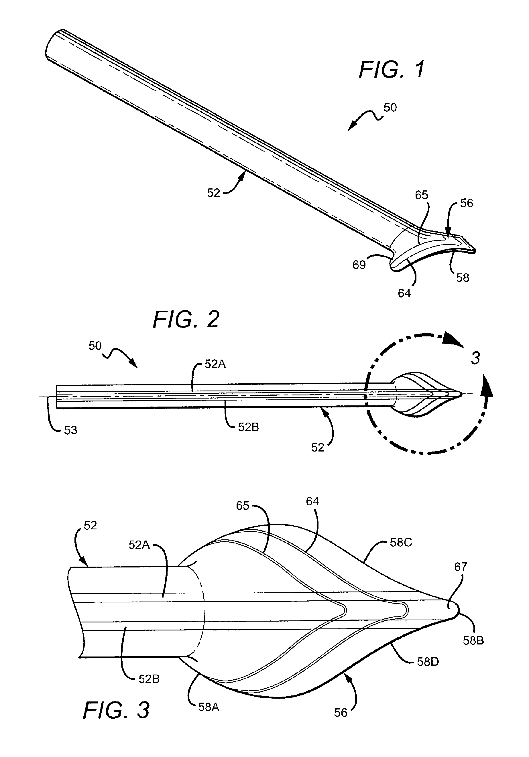
FIG. 1 is a perspective view of one embodiment of a vascular cuff graft with trim lines.
FIG. 2 is a top view of the vascular cuff graft of FIG. 1
FIG. 3 is an enlarged view of the cuff of the vascular cuff graft shown in FIG. 2.
FIG. 4 is a perspective view of the vascular cuff graft of FIG. 1 disposed over a section of a mold.
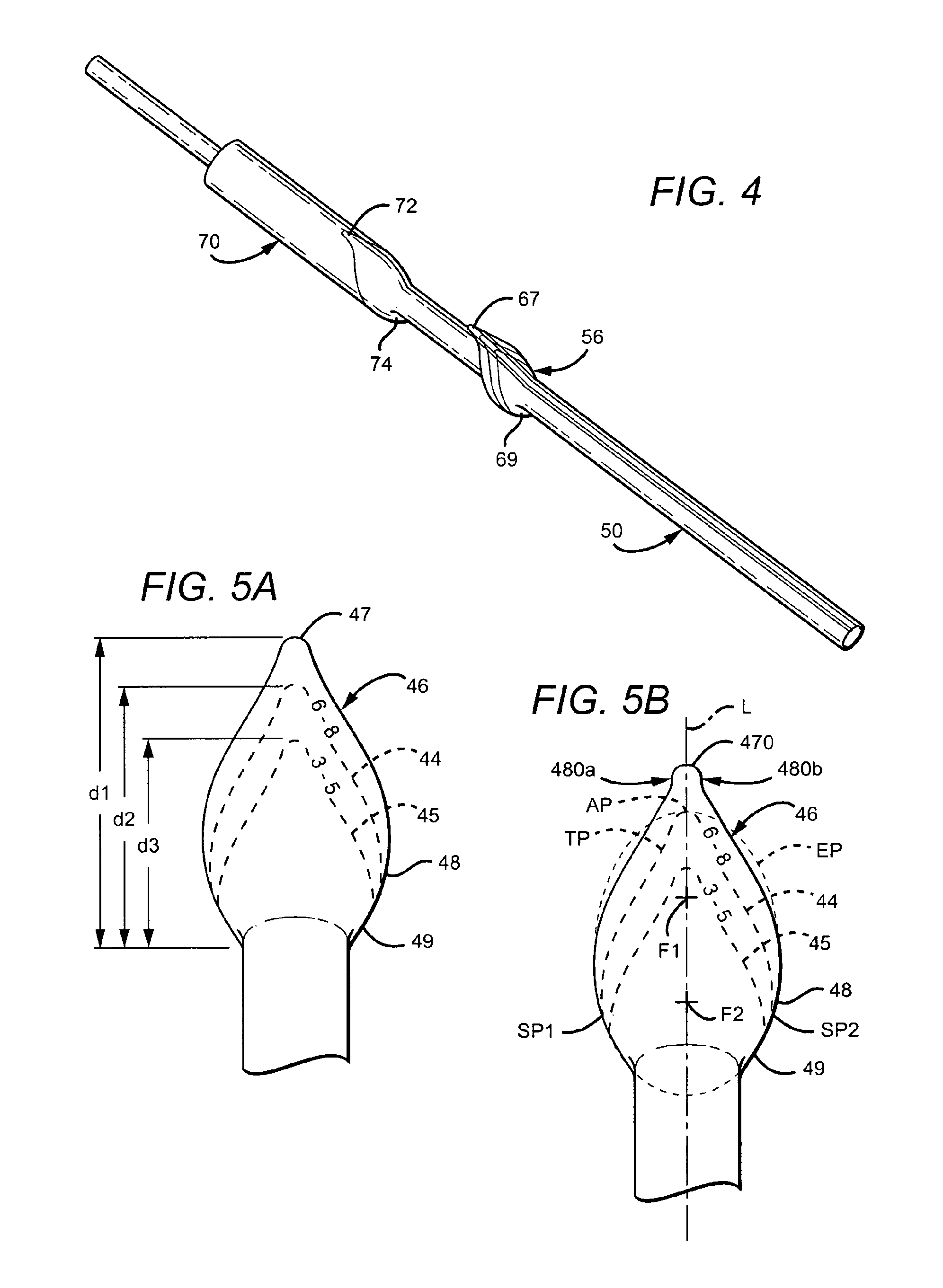
FIG. 5A is a top view of another embodiment of a vascular cuff graft with trim lines.
FIG. 5B is a top view of another embodiment of a vascular cuff graft with trim lines.
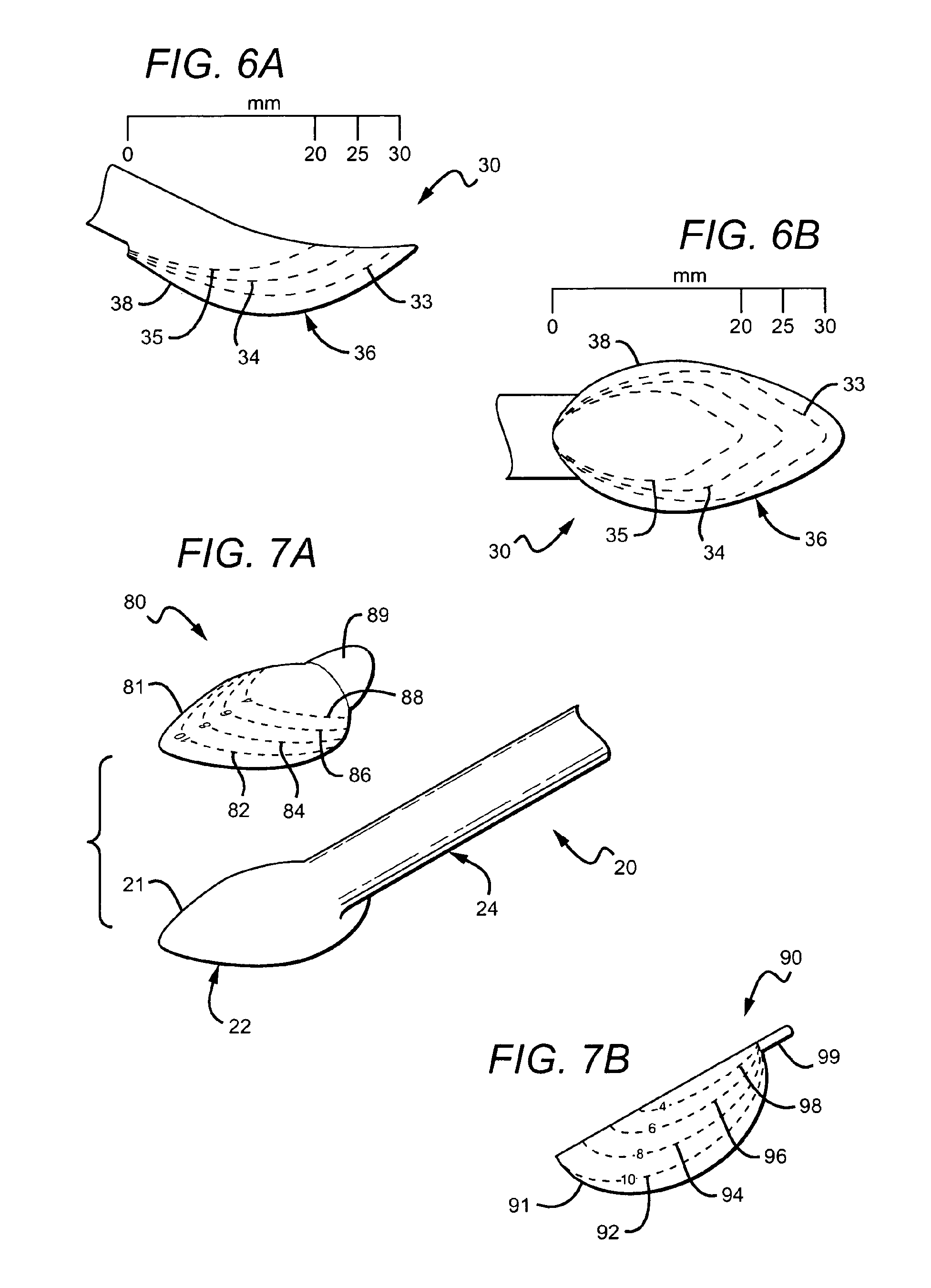
FIG. 6A is a side view of another embodiment of a vascular cuff graft with trim lines.
FIG. 6B is a top view of the vascular cuff graft of FIG. 6A.
FIG. 7A is one embodiment of a template for disposition over a cuff of a vascular cuff graft.
FIG. 7B is another embodiment of a template for disposition over a cuff of a vascular cuff graft.
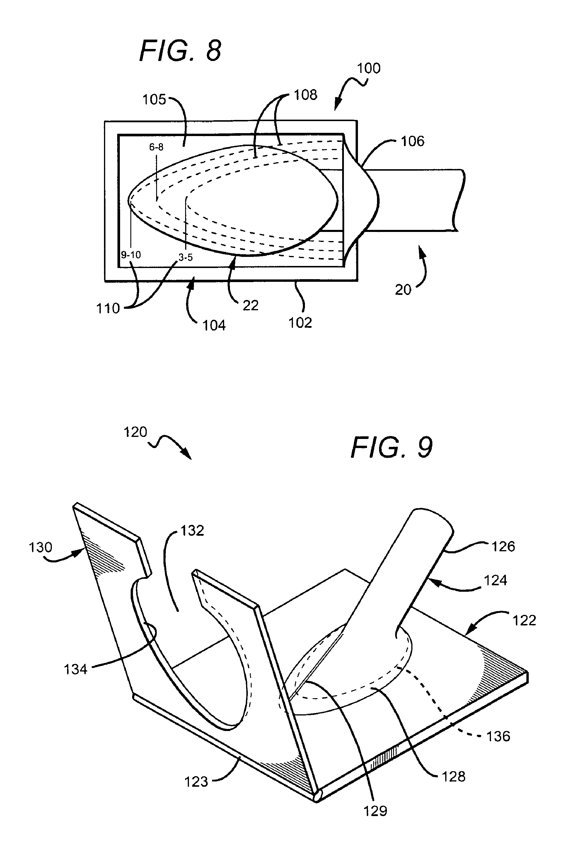
FIG. 8 is one embodiment of a pocket template into which a cuff of a vascular graft is disposed.
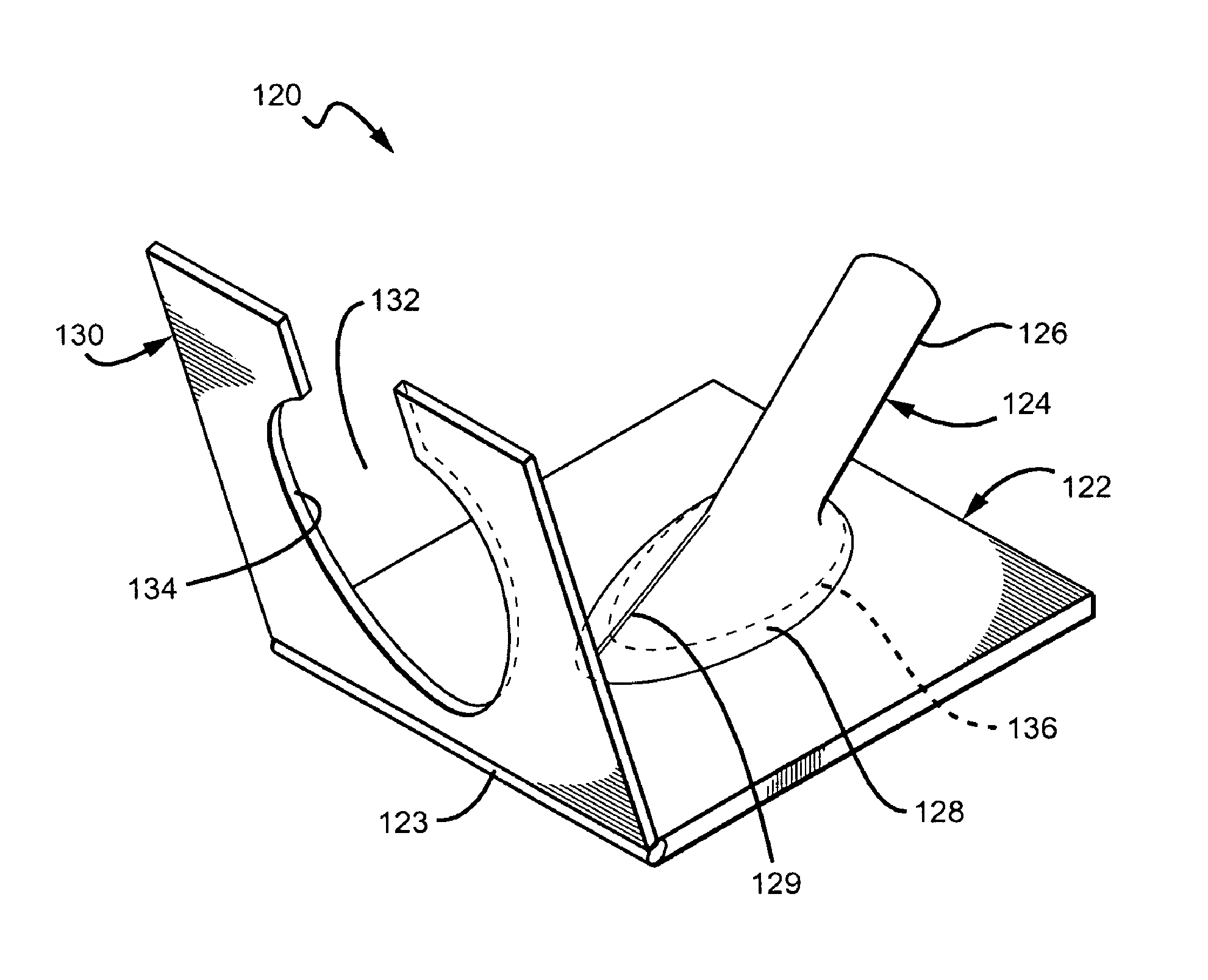
FIG. 9 is one embodiment of a trimming apparatus used to facilitate and ensure precise trimming of a cuff of a vascular graft.
DETAILED DESCRIPTION OF THE PREFERRED EMBODIMENTS
The following detailed description should be read with reference to the drawings, in which like elements in different drawings are identically numbered. The drawings, which are not necessarily to scale, depict selected embodiments and are not intended to limit the scope of the invention. The detailed description illustrates by way of example, not by way of limitation, the principles of the invention. This description will clearly enable one skilled in the art to make and use the invention, and describes several embodiments, adaptations, variations, alternatives and uses of the invention, including what is presently believed to be the best mode of carrying out the invention.
One embodiment of a vascular cuff graft is illustrated in FIGS. 1-3. Vascular cuff graft 50 includes a tubular member 52 and an outwardly flared skirt or cuff 56 extending from one end of the tubular member 52. The cuff 56 is offset from the longitudinal axis 53 such that one focal point of the cuff is positioned a greater distance from the longitudinal axis 53 than another focal point of the cuff. The cuff 56 includes a toe section 67, which projects away from the tubular member 52 in one direction, and a heel section 69, which projects away from the tubular member 52 in the opposite direction.
The cuff 56 in the embodiment shown in FIGS. 1-3 is continuous and integral with the tubular member 52, without any intervening seams or overlap. The tubular member 52 and/or cuff 56 may be formed from a suitable biocompatible material such as, for example, from polytetrafluoroethylene, polyester, polyurethane, or fluoropolymers, such as perfluoroelastomers, and combinations thereof; however, in the preferred embodiment, ePTFE is used to form the tubular member 52 and cuff 56. The thickness of vascular graft 50 in one embodiment is approximately 0.9 mm and can vary along the length of the graft. Preferably, the vascular graft 50 is thinner at the cuff 56 and thicker along the tubular member 52. According to preferred embodiments, a coiled beading made of PTFE may be helically wound about an outer surface of the tubular member 52 to reduce kinking. The beading can be impregnated with a radiopaque material, such as barium sulfate or hydroxyapatite, to increase visibility under radio imaging (e.g., x-ray).
Bioactive agents may be incorporated into the vascular cuff graft 50, including, but not limited to, activated charcoal, carbon particles, graphite particles, vasodilator, anti-coagulants, such as, for example, warfarin and heparin. Other bio-active agents can also include, but are not limited to agents such as, for example, anti-proliferative/antimitotic agents including natural products such as vinca alkaloids (i.e. vinblastine, vincristine, and vinorelbine), paclitaxel, epidipodophyllotoxins (i.e. etoposide, teniposide), antibiotics (dactinomycin (actinomycin D) daunorubicin, doxorubicin and idarubicin), anthracyclines, mitoxantrone, bleomycins, plicamycin (mithramycin) and mitomycin, enzymes (L-asparaginase which systemically metabolizes L-asparagine and deprives cells which do not have the capacity to synthesize their own asparagine); antiplatelet agents such as G(GP) II.sub.b/III.sub.a inhibitors and vitronectin receptor antagonists; anti-proliferative/antimitotic alkylating agents such as nitrogen mustards (mechlorethamine, cyclophosphamide and analogs, melphalan, chlorambucil), ethyl enimines and methylmelamines (hexamethylmelamine and thiotepa), alkyl sulfonates-busulfan, nirtosoureas (carmustine (BCNU) and analogs, streptozocin), trazenes-dacarbazinine (DTIC); anti-proliferative/antimitotic antimetabolites such as folic acid analogs (methotrexate), pyrimidine analogs (fluorouracil, floxuridine, and cytarabine), purine analogs and related inhibitors (mercaptopurine, thioguanine, pentostatin and 2-chlorodeoxyadenosine {cladribine}); platinum coordination complexes (cisplatin, carboplatin), procarbazine, hydroxyurea, mitotane, aminoglutethimide; hormones (i.e. estrogen); anti-coagulants (heparin, synthetic heparin salts and other inhibitors of thrombin); fibrinolytic agents (such as tissue plasminogen activator, streptokinase and urokinase), aspirin, dipyridamole, ticlopidine, clopidogrel, abciximab; antimigratory; antisecretory (breveldin); anti-inflammatory: such as adrenocortical steroids (cortisol, cortisone, fludrocortisone, prednisone, prednisolone, 6.alpha.-methylprednisolone, triamcinolone, betamethasone, and dexamethasone), non-steroidal agents (salicylic acid derivatives i.e. aspirin; para-aminophenol derivatives i.e. acetominophen; indole and indene acetic acids (indomethacin, sulindac, and etodalac), heteroaryl acetic acids (tolmetin, diclofenac, and ketorolac), arylpropionic acids (ibuprofen and derivatives), anthranilic acids (mefenamic acid, and meclofenamic acid), enolic acids (piroxicam, tenoxicam, phenylbutazone, and oxyphenthatrazone), nabumetone, gold compounds (auranofin, aurothioglucose, gold sodium thiomalate); immunosuppressives: (cyclosporine, tacrolimus (FK-506), sirolimus (rapamycin), azathioprine, mycophenolate mofetil); angiogenic agents: vascular endothelial growth factor (VEGF), fibroblast growth factor (FGF); angiotensin receptor blockers; nitric oxide donors; anti-sense oligionucleotides and combinations thereof; cell cycle inhibitors, mTOR inhibitors, and growth factor receptor signal transduction kinase inhibitors; retenoids; cyclin/CDK inhibitors; HMG co-enzyme reductase inhibitors (statins); and protease inhibitors.
The vascular cuff graft 50 may include an alignment guide that is printed or otherwise marked on an outer surface of the tubular member 52. The alignment guide in the embodiment shown in FIGS. 1-3 includes a pair of lines 52A and 52B, which extend generally parallel to a central longitudinal axis 53 of the vascular cuff graft 50. In other embodiments, the alignment guide may include one line or three or more lines, or may include a different type of marking. The alignment guide may extend onto the cuff 56 as shown in FIGS. 1-3. As shown in the enlarged view of FIG. 3, the cuff 56 has an edge 58 defining an outer perimeter, including opposing convex portions 58A, 58B and opposing concave portions 58C, 58D. The edge 58 in a preferred embodiment is an edge previously trimmed by a vascular surgeon from a conventional elliptically-shaped cuff prior to attachment to a vessel, as explained below in connection with FIGS. 6A-6B.
Markings, such as trim lines 64 and 65, are positioned on a top surface of the cuff 56 to provide alternatives to a vascular surgeon for tailoring the size of the cuff 56, depending on the vessel to which it is to be attached. In the embodiment shown in FIGS. 1-3, the trim lines 64 and 65 are spaced from one another and generally follow the shape of the edge 58 of the cuff 56 (i.e., the trim lines 64, 65 and the edge 58 are generally parallel to one another). The shape of the edge 58, as mentioned, is different from the elliptical shape of the perimeter of a conventional bulb-like cuff from which it is preferably cut. However, in other embodiments, each of the trim lines may be positioned on a surface of the cuff in patterns different from one another such that the surgeon may choose a different shape for the cuff depending on a particular need. The trim lines 64, 65 may be solid or dashed (see FIG. 5A). The trim lines 64, 65 (and peripheral edge 58 prior to trimming) permit a vascular surgeon to tailor the cuff 56 to a specific size or shape determined during an implant procedure to accommodate the open arteriotomy at an anastomotic site. The trim lines and other indicia may be printed on a surface of the cuff 56 using inks as described below.
Preferred formulations for inks provide different colors. For example, a bright cobalt blue line at 33% urethane is provided by dissolving three grams urethane in 17 grams THF (a 12% solution is preferable), then mixing in 1.0 grams cobalt blue. A dark blue line that is an FDA safe mixture includes FD&C #2 at 1% of urethane and cobalt blue at 2% urethane, which is provided by dissolving 0.3 grams FD&C #2 in 15 grams of water and heating to approximately 150 degrees C.; adding 20 grams of DMAc to the water solution, making an azeotrope, and shaking well; adding 15 grams of urethane to 85 grams of THF and dissolving thoroughly (15% solution); adding 3.5 grams of the DMAc water solution to the 100 grams of the urethane/THF solution; and adding 0.3 grams cobalt blue to the resulting solution and shaking well. Commercially available inks may also be used. For example, TPR Ink manufactured by Marabuwerke GmbH & Co. (Tamm, Germany), is available from Autoroll Print Technologies, LLC (Middleton, Mass.; part number 3803 57 980). As a thinner for the TPR Ink, TPV Thinner, also manufactured by Marabuwerke GmbH & Co., is also available from Autoroll Print Technologies, LLC (part number 3501 97 046). Also, TPU ink, manufactured by Marabuwerke GmbH & Co., may be used.
An integral cuff 56 may be formed, for example, by any of a variety of methods known to one skilled in the art, such as, for example, using the apparatus and method described in U.S. Pat. No. 6,190,590 to Randall et al. Referring to FIG. 4, one preferred method of forming a vascular cuff graft 50 includes selectively expanding a section of an ePTFE tube using a mold 70. The mold 70 may include specific contours that correspond to a cuff, such as cuff 56. For example, the toe section 67 of the cuff 56 corresponds to a toe contour 72 of mold 70 and the heel section 69 of the cuff 56 corresponds to a heel contour of the mold 70. In another embodiment, the cuff 56 could be separately formed and attached to the tubular member 52 using methods known to one skilled in the art (e.g., suture, heat, adhesives, etc.).
In addition to trim lines on a surface thereof, the cuff may include printed indicia as shown in FIG. 5A on a cuff 46. Cuff 46 is similar to cuff 56 but which could include a toe 47 that is more pointed than toe 67. In the example shown, the printed indicia on cuff 46 is in line with trim lines 44, 45 to indicate to a surgeon the diameter size of the vein or vessel for each line. As with edge 58 of cuff 56, the edge 48 defining a perimeter of cuff 46 is preferably an edge previously trimmed by a vascular surgeon from a conventionally-shaped cuff prior to attachment to a vessel, as described below. The sizing along the outer peripheral edge 48 is designed for a vessel having a diameter from approximately 9 mm to approximately 10 mm (and may previously had numerical indicia associated therewith (e.g., "9-10") prior to trimming). Trim line 44 includes numerical indicia "6-8" to indicate that the surgeon should trim the cuff 46 along line 44 if the vessel is from approximately 6 mm to approximately 8 mm. Trim line 45 includes numerical indicia "3-5" to indicate that the surgeon should trim the cuff 46 along line 45 if the native vessel is from approximately 3 mm to approximately 5 mm. The numerical indicia in this embodiment is positioned in-line with the trim lines 44, 45; however, in other embodiments, the numerical indicia can be adjacent the trim line along any section thereof. The lengths of the cuff 22 or distance between heel and toe, depending on the trim line chosen in this embodiment are as follows: the distance d.sub.1 between the heel 49 and toe 47 in the cuff 46 trimmed along outer peripheral edge 48 is approximately 30 mm; the distance d.sub.2 between the heel and toe on the cuff trimmed along line 44 is approximately 25 mm; and the distance d.sub.3 between the heel and toe on the cuff trimmed along line 45 is approximately 20 mm.
By virtue of the various embodiments described herein, a method of trimming a vascular graft is realized. In such method, the graft has a generally tubular body that defines a longitudinal axis extending through the generally tubular body. The method can be achieved by providing a flared end connected to the generally tubular body, shown here in FIG. 5B, and cutting the flared end along a trimmed perimeter smaller than a generally elliptical boundary having two foci on a common axis. As shown in FIG. 5B, the flared end or cuff 46 is precut to a first configuration for native vessel larger than 8 mm so that a clinician is not required to trim the graft for optimum hemodynamic characteristics. It is noted that, in this embodiment, the toe 470 is different that the toe 47 of FIG. 5A in that the toe 470 is connected to the graft via generally linear portions 470a and 470b. For vessel 8 mm or smaller, trim lines 44 and 45 are provided. Each trim line has an apex located generally on a common axis of a virtual generally elliptical boundary EP. For example, trim line 44 has apex AP located generally on the common axis L (which, coincidentally, in the view of FIG. 5B, the longitudinal axis 53 and common axis L are on axis) as defined by the foci F1 and F2 of the virtual ellipse boundary EP. Upon trimming along the line 44 by a clinician, a trimmed perimeter TP is provided that defines a border 44 (dashed lines) contiguous to the generally elliptical boundary EP at a first location disposed on the common axis L, e.g., AP and at least two other locations SP1 and SP2 disposed generally symmetrically about the common axis L. And the first location (at apex AP) may include a farthest terminal end of the vascular graft once the cuff has been trimmed. In such method, the flared end can be a separate member or it can be an integral and monolithic part of the generally tubular body.
As discussed above, known vascular grafts with a bulbous-like flange or cuff are believed to lead to an enlargement of anastomotic room with a curved vein floor when attached to a vein in an end-to-side anastomotic procedure. Simulated flow studies related to these cuff grafts suggest that blood flow patterns are optimized in comparison to other prior grafts. However, the positive properties associated with the cuff graft are closely tied to the correct design of the venous anastomosis. Regardless of the manufactured size and shape, the cuff generally must be trimmed somewhat prior to attachment to a vein. However, even in instances when trimming instructions are provided, if the trimming advice is not followed exactly and the cuff not trimmed precisely on the dotted lines or markings indicated, there is believed to be an increased risk of sub-optimal results, one of which is the formation of a hooded region proximate the attachment point of the toe.
FIGS. 6A and 6B show a preferred embodiment of a cuff graft 30 to address this potential problem. Cuff graft 30 is shown with three trim lines 33, 34, 35 on a surface of a cuff 36 spaced approximately 5 mm from each other as depicted. Of course, the intervals between trim lines can be greater or less than 5 mm and the distances between trim lines can also be varied. The outer periphery 38 of the cuff 36 has a conventional bulb-like form, but is not intended for use. Instead, as shown in FIG. 6B, a modified trim pattern for each of the trim lines 33, 34, 35 is provided. In this embodiment, the distance between the heel and the toe on the cuff trimmed along line 33 is approximately 30 mm; the distance between the heel and toe on the cuff trimmed along line 34 is approximately 25 mm; and the distance between the heel and toe on the cuff trimmed along line 35 is approximately 20 mm.
Referring back to FIGS. 1-5, perimeter edges 48, 58 of cuffs 46, 56 are preferably trim lines on a preferred vascular graft prior to trimming by a surgeon. Where the native vessel is greater than 8 mm, no trimming is needed due to the pre-configured perimeter edge 48. Where the native vessel is from approximately 6 mm to approximately 8 mm, trim edge 44 is provided (e.g., printed) on the cuff end of the graft. Where the native vessel is from approximately 3 mm to approximately 5 millimeter, trim edge guide 45 is provided (e.g., printed) on the cuff of the graft.
The study presented in the paper entitled "The Importance of Correct Trimming of Venaflo Graft Proven by CFD," presented at the 4th International Congress of the Vascular Access Society, May 25 to 27, 2005, Berlin, Germany, describes how graft geometry at the site of a venous anastomosis directly affects hemodynamic factors. In particular, the study found that the precise trimming of a cuff along modified lines, such as lines 33, 34 and 35 in cuff graft 30, and particularly in predefined perimeters 44, 45, and 46 resulted in measurable advantages over cuff grafts with untrimmed conventional bulb-like cuff configurations and/or cuffs that were not precisely trimmed according to the vein diameter at maximum dilation of the target vein. Such advantages include an enlarged anastomotic room, leading to durable flow separation and a prolonged three-dimensional vortex with clockwise rotation, a reduction of pressure rise due to fluid stagnation at the vein floor, and reduced shear stress on the vein floor (which is believed to lead to delayed, reduced or elimination of intimal hyperplasia and venous anastomotic stenosis). Thus, it is believed that precise trimming of a cuff graft, according to the particular perimeter shown and described herein, imparts surprising benefits to the cuff graft at least with respect to the advantages mentioned.
In another embodiment, rather than printing indicia and/or trim lines on a surface of the cuff of a cuff graft, a sizing template may be provided for a conventional cuff graft to enable precise trimming of the cuff to achieve the advantages discussed above. FIG. 7A illustrates one embodiment of a sizing template 80 configured to be positioned over a bulb-like cuff 22 of a conventional cuff graft 20. In one embodiment, the template 80 is a section of material, such as a film, with adhesive disposed on one side. On the non-adhesive side of the template 80, markings, such as trim lines, indicia, etc., are disposed to aid a vascular surgeon in precise trimming of the graft. In the embodiment shown, the film is a clear/transparent plastic having pre-printed markings; however in other embodiments, the film or like material may be translucent or partially transparent and partially translucent.
As shown in FIG. 7, the template 80 may have four trim lines, 82, 84, 86, 88, for sizing the cuff 22 to a different diameter vessel when trimmed along the trim lines. Thus, in the example shown, for a vessel having a maximum dilation of 10 mm, the vascular surgeon would trim along trim line 82 following attachment of the template 80 to the cuff 22. Likewise, for a vessel having a maximum dilation of 8 mm, 6 mm and 4 mm, the surgeon would trim along lines 84, 86 and 88, respectively. The peripheral edge 81 of template 80 in the preferred embodiment is shaped substantially similar to the cuff on which it is to be placed so that the edge 81 of the template 80 can be matched with the edge 21 of the cuff 20 to ensure precise trimming of the cuff 20. Also, in the embodiment shown, template 80 includes a tab 89 without an adhesive backing in order to facilitate removal of the template 80 following the trimming procedure.
The template 80 may be positioned over a cuff prior to packaging and sold together as a unit, or may be packaged separately from a cuff such that it must be placed over the cuff prior to trimming by a surgeon as described above. In one embodiment, the template 80 is halved such that it is configured to be placed over only a portion of the cuff 22. Thus, the cuff 22 is first folded in half along a line of symmetry prior to attaching a half-sized template 90 with adhesive backing, shown in FIG. 7B, to one half of the cuff 22. As with the full-size template 80, template 90 includes a peripheral edge 91 to match the peripheral edge of the folded-in-half cuff 22, and four trim lines 92, 94, 96, 98, for sizing the cuff 22 to a different diameter vessel when trimmed along the trim lines. The template 90 may also include a tab 99 without adhesive backing. While four trim lines are indicated in FIGS. 7A and 7B, it should be appreciated that the templates 80, 90 could have less than four trim lines or more than four trim lines, with each trim line being indicated for a different diameter target vessel.
In another embodiment, shown in FIG. 8, a pocket 100 is provided for housing a cuff 22 of a cuff graft 20. The pocket 100 may be formed of two overlying sheets of film 104 with peripheral edges 102 that are configured to be coupled together to form a void in which the cuff 22 is disposed. The edges 102 may have adhesive disposed on one side thereof or may be otherwise coupled together by methods known to one skilled in the art (e.g., heat, chemical bonding, etc.). Alternatively, the pocket 100 may be formed of a single sheet of film folded along a symmetry line, having edges configured for coupling as discussed. The coupling of the sheets of film 104 (or sheet) along peripheral edges 102 may be continuous or intermittent, although it is preferred that the pocket 100 be sealed along the edges 102 except for the portion through which the cuff graft is positioned. The sheet or sheets of film 104 include at least one side with a clear or transparent face 105 such that the cuff 22 can be viewed by a user. The face 105 includes a template with trim lines 108 and/or indicia 110 to guide a surgeon in the trimming of the cuff 22 based on the diameter of the vessel to which it is to be attached, as discussed above. It is noted that the face 105 of both sides of the pocket 100 may include a template with trim lines 108 and/or indicia 110, such that the cuff may be inserted or positioned with the top surface adjacent either face 105.
Opposing tabs 106, each positioned on one side of an inserted cuff graft 20, are provided on the pocket 100 to facilitate removal of the pocket 100 following the trimming of the cuff 22. In the embodiment shown, the pocket 100 is rectangular; however, the pocket may be in any shape including the shape of the cuff 22. The pocket 100 may be positioned over a cuff 22 of a cuff graft 20 and sold as a unit, or may be sold or packaged separately for assembly by an end user. When sold as a unit, the cuff 22 is secured within the pocket 100 such that cutting along the trim lines results in an optimal size and shape of the cuff 22 for attaching to a blood vessel of desired size. The cuff 22 may be secured, for example, by shrinking slightly the material of the pocket 100, by sizing the pocket 100 slightly smaller than the cuff 22 so that the toe and side edge are sealed into the edges of the pocket 100, by applying a thin coat of medical grade lubricant to the inside of the pocket in order to contact the top of the cuff to adhere the cuff 22 to the pocket 100, or other methods known to one skilled in the art. In another embodiment, a half-sized pocket is provided to accommodate a cuff 22 that has been folded along a line of symmetry. This pocket would have partial markings, including a template with trim lines and/or indicia, similar to the half-sized template described above.
In another embodiment illustrated in FIG. 9, a trimming apparatus 120 is provided to ensure precise trimming of the cuff 22 of a cuff graft 20 to achieve desired advantages. The trimming apparatus 120 includes a base 122, including a mandrel 124 shaped to receive a cuff graft 20 thereover, the mandrel 124 having a tubular section 126 and a flared section 128 shaped to correspond to the tubular section and cuff section of a cuff graft (e.g., the flared section 128 includes a heel section and a toe section to correspond to a heel and toe of a cuff). In one embodiment, the mandrel 124 has disposed thereon a register, which may be a pair of lines 129 positioned on the flared section 128 to correspond to the alignment guide 24 on the cuff graft 20, such that the proper positioning of the cuff graft 20 onto the mandrel 124 is both facilitated and ensured. In other embodiments, the register may be one or more features such as markings, mating shapes, etc., to ensure proper positioning of the cuff graft 20 so that precise trimming of the cuff 22 is achieved and to facilitate the process.
Pivotally attached (e.g., via a hinge, etc.) to the base 122 along an edge 123 adjacent a toe portion of the flared section 128 is a template 130. The template 130 includes an opening 132 configured in the desired pattern for a cuff of a cuff graft to achieve optimal flow conditions for a particular diameter vessel, as discussed above. Thus, in one embodiment, the opening 132 includes a section with opposing convex portions to create opposing concave portions on the cuff 22 of a cuff graft 20 positioned over the mandrel 124 (e.g., FIG. 6B). When the template 130 is pivoted toward the mandrel 124, following the positioning of a cuff graft 20 thereover, the edge 134 of the opening 132 engages the cuff 22 of a cuff graft 20 placed over the mandrel 124 generally along the area depicted by dotted line 136. In one embodiment, the edge 134 includes a sharp cutting blade or surface, such that engagement with the cuff 22 results in the trimming thereof according to the outline of the edge 134. In other embodiments, the edge 134 is blunt and engagement with the cuff 22 provides an outline along which the surgeon or clinician can trim, either while the edge 134 of the template 130 is engaged with the cuff 22 or by creating an impression on the cuff to guide the trimming thereof after the template 130 is pivoted away therefrom.
In the example shown in FIG. 9, the outline of the edge 134 is for a large diameter vessel (e.g., 9-10 mm), such that trimming for smaller vessels can take place, in one embodiment, through the use of one or more separate cutout members that mate with the opening 132 and are nested therein. For example, a cutout member for the trimming of a cuff 22 for attachment to a 6 mm diameter vessel would have an inside edge corresponding to the optimal shape and size of a cuff therefore and an outside edge to mate with edge 134. The cutout member could be attached to the opening 132 via one or more locking mechanisms or detachable connections (e.g., snap fit, latch, Velcro, etc.) prior to pivoting over the cuff 22. The cutout members could either have a sharp cutting blade or surface to trim upon engagement with the cuff 22 or have a blunt edge to permit trimming of the cuff 22 by the surgeon or clinician, as discussed above.
In another embodiment, the opening 132 is adjustable, depending on the size and shape desired. For example, the opening 132 may include an adjustable edge or surface that can be slid or moved into a desired position depending on the diameter of the vessel to which the cuff 22 is to be attached. Settings could be provided for each of a number of different diameter vessels and each setting could include a locking mechanism. For example, the opening 132 may have an adjustable edge with settings for a 3-5 mm diameter vessel and a 6-8 diameter vessel, assuming that the original opening 132 is configured to correspond to an optimal shape and size for attaching to a 9-10 diameter vessel. Thus, to adjust the edge for a smaller diameter vessel, a locking pin or like mechanism could be adjusted to move the edge inward. The adjustable edge could include numeric indicia on a surface thereof to indicate to a user the diameter of vessel for each setting. In one embodiment, the cutout member is adjustable to provide the ability to trim to several different sizes and shapes of cuffs based on need, the cutout member having an outside surface and contour that mates with the inside surface of the opening 132, and an inside surface that can be adjusted to different shapes and/or sizes.
This invention has been described and specific examples of the invention have been portrayed. While the invention has been described in terms of particular variations and illustrative figures, those of ordinary skill in the art will recognize that the invention is not limited to the variations or figures described. In addition, where methods and steps described above indicate certain events occurring in certain order, those of ordinary skill in the art will recognize that the ordering of certain steps may be modified and that such modifications are in accordance with the variations of the invention. Additionally, certain of the steps may be performed concurrently in a parallel process when possible, as well as performed sequentially as described above. Therefore, to the extent there are variations of the invention, which are within the spirit of the disclosure or equivalent to the inventions found in the claims, it is the intent that this patent will cover those variations as well. Finally, all publications and patent applications cited in this specification are herein incorporated by reference in their entirety as if each individual publication or patent application were specifically and individually put forth herein.
* * * * *
D00000
D00001
D00002
D00003
D00004
XML
uspto.report is an independent third-party trademark research tool that is not affiliated, endorsed, or sponsored by the United States Patent and Trademark Office (USPTO) or any other governmental organization. The information provided by uspto.report is based on publicly available data at the time of writing and is intended for informational purposes only.
While we strive to provide accurate and up-to-date information, we do not guarantee the accuracy, completeness, reliability, or suitability of the information displayed on this site. The use of this site is at your own risk. Any reliance you place on such information is therefore strictly at your own risk.
All official trademark data, including owner information, should be verified by visiting the official USPTO website at www.uspto.gov. This site is not intended to replace professional legal advice and should not be used as a substitute for consulting with a legal professional who is knowledgeable about trademark law.