Method and system for performing invasive medical procedures using a surgical robot
Smith , et al. J
U.S. patent number 10,172,678 [Application Number 14/729,096] was granted by the patent office on 2019-01-08 for method and system for performing invasive medical procedures using a surgical robot. This patent grant is currently assigned to GLOBUS MEDICAL, INC.. The grantee listed for this patent is GLOBUS MEDICAL, INC.. Invention is credited to Neil Crawford, Regina DeSanctis-Smith, Alan M. Pitt, David W. Smith, Nicholas Theodore.


View All Diagrams
| United States Patent | 10,172,678 |
| Smith , et al. | January 8, 2019 |
Method and system for performing invasive medical procedures using a surgical robot
Abstract
A method and system for performing invasive procedures includes a surgical robot which is controlled by a guidance system that uses time of flight calculations from RF transmitters embedded in the robot, surgical instrument, and patient anatomy. Sensors around the room detect RF transmissions emitted by the RF transmitters and drive the robot according to a preprogrammed trajectory entered into the guidance system.
| Inventors: | Smith; David W. (Scottsdale, AZ), DeSanctis-Smith; Regina (Scottsdale, AZ), Pitt; Alan M. (Phoenix, AZ), Theodore; Nicholas (Phoenix, AZ), Crawford; Neil (Tempe, AZ) | ||||||||||
|---|---|---|---|---|---|---|---|---|---|---|---|
| Applicant: |
|
||||||||||
| Assignee: | GLOBUS MEDICAL, INC. (Audubon,
PA) |
||||||||||
| Family ID: | 39733725 | ||||||||||
| Appl. No.: | 14/729,096 | ||||||||||
| Filed: | June 3, 2015 |
Prior Publication Data
| Document Identifier | Publication Date | |
|---|---|---|
| US 20150335386 A1 | Nov 26, 2015 | |
Related U.S. Patent Documents
| Application Number | Filing Date | Patent Number | Issue Date | ||
|---|---|---|---|---|---|
| 13542560 | Jul 5, 2012 | 9078685 | |||
| 11845557 | Jul 10, 2012 | 8219178 | |||
| 11838027 | Jul 10, 2012 | 8219177 | |||
| 11676023 | Aug 30, 2011 | 8010181 | |||
| Current U.S. Class: | 1/1 |
| Current CPC Class: | A61B 34/30 (20160201); A61B 34/20 (20160201); A61B 90/10 (20160201); A61B 17/7076 (20130101); A61B 90/36 (20160201); A61B 5/06 (20130101); A61B 90/11 (20160201); A61B 34/73 (20160201); A61B 2090/3937 (20160201); A61B 2034/2072 (20160201); A61B 2034/107 (20160201); A61B 2034/2057 (20160201); A61B 2034/2051 (20160201); A61B 2017/00057 (20130101); A61B 2017/00398 (20130101); A61B 2034/301 (20160201); A61B 34/25 (20160201); A61B 17/3478 (20130101) |
| Current International Class: | A61B 34/30 (20160101); A61B 34/20 (20160101); A61B 5/06 (20060101); A61B 90/10 (20160101); A61B 34/00 (20160101); A61B 90/00 (20160101); A61B 90/11 (20160101); A61B 17/34 (20060101); A61B 34/10 (20160101) |
References Cited [Referenced By]
U.S. Patent Documents
| 5354314 | October 1994 | Hardy et al. |
| 5397323 | March 1995 | Taylor et al. |
| 5772594 | June 1998 | Barrick |
| 5791908 | August 1998 | Gillio |
| 5820559 | October 1998 | Ng et al. |
| 5825982 | October 1998 | Wright et al. |
| 5887121 | March 1999 | Funda et al. |
| 5911449 | June 1999 | Daniele et al. |
| 5951475 | September 1999 | Gueziec et al. |
| 6012216 | January 2000 | Esteves et al. |
| 6033415 | March 2000 | Mittelstadt et al. |
| 6080181 | June 2000 | Jensen et al. |
| 6106511 | August 2000 | Jensen |
| 6122541 | September 2000 | Cosman et al. |
| 6157853 | December 2000 | Blume et al. |
| 6167145 | December 2000 | Foley et al. |
| 6167292 | December 2000 | Badano et al. |
| 6201984 | March 2001 | Funda et al. |
| 6205411 | March 2001 | DiGioia, III et al. |
| 6212419 | April 2001 | Blume et al. |
| 6231565 | May 2001 | Tovey et al. |
| 6236875 | May 2001 | Bucholz et al. |
| 6246900 | June 2001 | Cosman et al. |
| 6301495 | October 2001 | Gueziec et al. |
| 6312435 | November 2001 | Wallace et al. |
| 6314311 | November 2001 | Williams et al. |
| 6322567 | November 2001 | Mittelstadt et al. |
| 6325808 | December 2001 | Bernard et al. |
| 6340363 | January 2002 | Bolger et al. |
| 6377011 | April 2002 | Ben-Ur |
| 6379302 | April 2002 | Kessman et al. |
| 6402762 | June 2002 | Hunter et al. |
| 6424885 | July 2002 | Niemeyer et al. |
| 6447503 | September 2002 | Wynne et al. |
| 6451027 | September 2002 | Cooper et al. |
| 6477400 | November 2002 | Barrick |
| 6484049 | November 2002 | Seeley et al. |
| 6490467 | December 2002 | Bucholz et al. |
| 6490475 | December 2002 | Seeley et al. |
| 6499488 | December 2002 | Hunter et al. |
| 6507751 | January 2003 | Blume et al. |
| 6535756 | March 2003 | Simon et al. |
| 6560354 | May 2003 | Maurer, Jr. et al. |
| 6565554 | May 2003 | Niemeyer |
| 6587750 | July 2003 | Gerbi et al. |
| 6614453 | September 2003 | Suri et al. |
| 6636757 | October 2003 | Jascob et al. |
| 6645196 | November 2003 | Nixon et al. |
| 6669635 | December 2003 | Kessman et al. |
| 6701173 | March 2004 | Nowinski et al. |
| 6738656 | May 2004 | Ferre |
| 6782287 | August 2004 | Grzeszczuk et al. |
| 6783524 | August 2004 | Anderson et al. |
| 6786896 | September 2004 | Madhani et al. |
| 6788018 | September 2004 | Blumenkranz |
| 6804581 | October 2004 | Wang et al. |
| 6823207 | November 2004 | Jensen et al. |
| 6827351 | December 2004 | Graziani et al. |
| 6837892 | January 2005 | Shoham |
| 6839612 | January 2005 | Sanchez et al. |
| 6856826 | February 2005 | Seeley et al. |
| 6856827 | February 2005 | Seeley et al. |
| 6879880 | April 2005 | Nowlin et al. |
| 6892090 | May 2005 | Verard et al. |
| 6920347 | July 2005 | Simon et al. |
| 6968224 | November 2005 | Kessman et al. |
| 6978166 | December 2005 | Foley et al. |
| 6991627 | January 2006 | Madhani et al. |
| 6999852 | February 2006 | Green |
| 7007699 | March 2006 | Martinelli et al. |
| 7063705 | June 2006 | Young et al. |
| 7072707 | July 2006 | Galloway, Jr. et al. |
| 7083615 | August 2006 | Peterson et al. |
| 7097640 | August 2006 | Wang et al. |
| 7130676 | October 2006 | Barrick |
| 7139418 | November 2006 | Abovitz et al. |
| 7139601 | November 2006 | Bucholz et al. |
| 7155316 | December 2006 | Sutherland et al. |
| 7164968 | January 2007 | Treat et al. |
| 7167738 | January 2007 | Schweikard et al. |
| 7169141 | January 2007 | Brock et al. |
| 7172627 | February 2007 | Fiere et al. |
| 7239940 | July 2007 | Wang et al. |
| 7248914 | July 2007 | Hastings et al. |
| 7302288 | November 2007 | Schellenberg |
| 7313430 | December 2007 | Urquhart et al. |
| 7318827 | January 2008 | Leitner et al. |
| 7319897 | January 2008 | Leitner et al. |
| 7327865 | February 2008 | Fu et al. |
| 7331967 | February 2008 | Lee et al. |
| 7333642 | February 2008 | Green |
| 7339341 | March 2008 | Oleynikov et al. |
| 7366562 | April 2008 | Dukesherer et al. |
| 7379790 | May 2008 | Toth et al. |
| 7386365 | June 2008 | Nixon |
| 7422592 | September 2008 | Morley et al. |
| 7435216 | October 2008 | Kwon et al. |
| 7440793 | October 2008 | Chauhan et al. |
| 7466303 | December 2008 | Yi et al. |
| 7493153 | February 2009 | Ahmed et al. |
| 7505617 | March 2009 | Fu et al. |
| 7533892 | May 2009 | Schena et al. |
| 7542791 | June 2009 | Mire et al. |
| 7555331 | June 2009 | Viswanathan |
| 7567834 | July 2009 | Clayton et al. |
| 7594912 | September 2009 | Cooper et al. |
| 7606613 | October 2009 | Simon et al. |
| 7607440 | October 2009 | Coste-Maniere et al. |
| 7630752 | December 2009 | Viswanathan |
| 7630753 | December 2009 | Simon et al. |
| 7643862 | January 2010 | Schoenefeld |
| 7660623 | February 2010 | Hunter et al. |
| 7689320 | March 2010 | Prisco et al. |
| 7691098 | April 2010 | Wallace et al. |
| 7702379 | April 2010 | Avinash et al. |
| 7711406 | May 2010 | Kuhn et al. |
| 7720523 | May 2010 | Omemick et al. |
| 7742801 | June 2010 | Neubauer et al. |
| 7751865 | July 2010 | Jascob et al. |
| 7762825 | July 2010 | Burbank et al. |
| 7763015 | July 2010 | Cooper et al. |
| 7787699 | August 2010 | Mahesh et al. |
| 7818044 | October 2010 | Dukesherer et al. |
| 7819859 | October 2010 | Prisco et al. |
| 7824401 | November 2010 | Manzo et al. |
| 7831294 | November 2010 | Viswanathan |
| 7834484 | November 2010 | Sartor |
| 7835557 | November 2010 | Kendrick et al. |
| 7835778 | November 2010 | Foley et al. |
| 7835784 | November 2010 | Mire et al. |
| 7840253 | November 2010 | Tremblay et al. |
| 7840256 | November 2010 | Lakin et al. |
| 7843158 | November 2010 | Prisco |
| 7844320 | November 2010 | Shahidi |
| 7853305 | December 2010 | Simon et al. |
| 7865269 | January 2011 | Prisco et al. |
| D631966 | February 2011 | Perloff et al. |
| 7879045 | February 2011 | Gielen et al. |
| 7881767 | February 2011 | Strommer et al. |
| 7881770 | February 2011 | Melkent et al. |
| 7886743 | February 2011 | Cooper et al. |
| RE42194 | March 2011 | Foley et al. |
| RE42226 | March 2011 | Foley et al. |
| 7907166 | March 2011 | Lamprecht et al. |
| 7909122 | March 2011 | Schena et al. |
| 7925653 | April 2011 | Saptharishi |
| 7930065 | April 2011 | Larkin et al. |
| 7935130 | May 2011 | Williams |
| 7940999 | May 2011 | Liao et al. |
| 7953470 | May 2011 | Vetter et al. |
| 7954397 | June 2011 | Choi et al. |
| 7971341 | July 2011 | Dukesherer et al. |
| 7974674 | July 2011 | Hauck et al. |
| 7974677 | July 2011 | Mire et al. |
| 7974681 | July 2011 | Wallace et al. |
| 7979157 | July 2011 | Anvari |
| 7983733 | July 2011 | Viswanathan |
| 7988215 | August 2011 | Seibold |
| 7996110 | August 2011 | Lipow et al. |
| 8004121 | August 2011 | Sartor |
| 8004229 | August 2011 | Nowlin et al. |
| 8010177 | August 2011 | Csavoy et al. |
| 8010181 | August 2011 | Smith |
| 8035685 | October 2011 | Jensen |
| 8046054 | October 2011 | Kim et al. |
| 8046057 | October 2011 | Clarke |
| 8054184 | November 2011 | Cline et al. |
| 8054752 | November 2011 | Druke et al. |
| 8057397 | November 2011 | Li et al. |
| 8057407 | November 2011 | Martinelli et al. |
| 8062288 | November 2011 | Cooper et al. |
| 8062375 | November 2011 | Glerum et al. |
| 8066524 | November 2011 | Burbank et al. |
| 8073335 | December 2011 | Labonville et al. |
| 8079950 | December 2011 | Stern et al. |
| 8092370 | January 2012 | Roberts et al. |
| 8105320 | January 2012 | Manzo |
| 8108025 | January 2012 | Csavoy et al. |
| 8109877 | February 2012 | Moctezuma de la Barrera et al. |
| 8112292 | February 2012 | Simon |
| 8120301 | February 2012 | Goldberg et al. |
| 8123675 | February 2012 | Funda et al. |
| 8133229 | March 2012 | Bonutti |
| 8142420 | March 2012 | Schena |
| 8147494 | April 2012 | Leitner et al. |
| 8150494 | April 2012 | Simon et al. |
| 8150497 | April 2012 | Gielen et al. |
| 8150498 | April 2012 | Gielen et al. |
| 8165658 | April 2012 | Waynik et al. |
| 8170313 | May 2012 | Kendrick et al. |
| 8179073 | May 2012 | Farritor et al. |
| 8182476 | May 2012 | Julian et al. |
| 8184880 | May 2012 | Zhao et al. |
| 8202278 | June 2012 | Orban, III et al. |
| 8208988 | June 2012 | Jensen |
| 8219177 | July 2012 | Smith |
| 8219178 | July 2012 | Smith |
| 8220468 | July 2012 | Cooper et al. |
| 8224484 | July 2012 | Swarup et al. |
| 8225798 | July 2012 | Baldwin et al. |
| 8228368 | July 2012 | Zhao et al. |
| 8231610 | July 2012 | Jo et al. |
| 8263933 | July 2012 | Hartmann et al. |
| 8239001 | August 2012 | Verard et al. |
| 8241271 | August 2012 | Millman et al. |
| 8248413 | August 2012 | Gattani et al. |
| 8256319 | September 2012 | Cooper et al. |
| 8271069 | September 2012 | Jascob et al. |
| 8271130 | September 2012 | Hourtash |
| 8281670 | October 2012 | Larkin et al. |
| 8282653 | October 2012 | Nelson et al. |
| 8301226 | October 2012 | Csavoy et al. |
| 8311611 | November 2012 | Csavoy et al. |
| 8320991 | November 2012 | Jascob et al. |
| 8332012 | December 2012 | Kienzle, III |
| 8333755 | December 2012 | Cooper et al. |
| 8335552 | December 2012 | Stiles |
| 8348931 | January 2013 | Cooper et al. |
| 8353963 | January 2013 | Glerum |
| 8358818 | January 2013 | Miga et al. |
| 8359730 | January 2013 | Burg et al. |
| 8374673 | February 2013 | Adcox et al. |
| 8374723 | February 2013 | Zhao et al. |
| 8392022 | March 2013 | Ortmaier et al. |
| 8394099 | March 2013 | Patwardhan |
| 8395342 | March 2013 | Prisco |
| 8398634 | March 2013 | Manzo et al. |
| 8400094 | March 2013 | Schena |
| 8414957 | April 2013 | Enzerink et al. |
| 8418073 | April 2013 | Mohr et al. |
| 8450694 | May 2013 | Baviera et al. |
| 8452447 | May 2013 | Nixon |
| RE44305 | June 2013 | Foley et al. |
| 8465476 | June 2013 | Rogers et al. |
| 8465771 | June 2013 | Wan et al. |
| 8467851 | June 2013 | Mire et al. |
| 8467852 | June 2013 | Csavoy et al. |
| 8469947 | June 2013 | Devengenzo et al. |
| RE44392 | July 2013 | Hynes |
| 8483434 | July 2013 | Buehner et al. |
| 8483800 | July 2013 | Jensen et al. |
| 8486532 | July 2013 | Enzerink et al. |
| 8489235 | July 2013 | Moll et al. |
| 8500722 | August 2013 | Cooper |
| 8500728 | August 2013 | Newton et al. |
| 8504201 | August 2013 | Moll et al. |
| 8506555 | August 2013 | Ruiz Morales |
| 8506556 | August 2013 | Schena |
| 8508173 | August 2013 | Goldberg et al. |
| 8512318 | August 2013 | Tovey et al. |
| 8515576 | August 2013 | Lipow et al. |
| 8518120 | August 2013 | Glerum et al. |
| 8521331 | August 2013 | Itkowitz |
| 8526688 | September 2013 | Groszmann et al. |
| 8526700 | September 2013 | Issacs |
| 8527094 | September 2013 | Kumar et al. |
| 8528440 | September 2013 | Morley et al. |
| 8532741 | September 2013 | Heruth et al. |
| 8541970 | September 2013 | Nowlin et al. |
| 8548563 | October 2013 | Simon et al. |
| 8549732 | October 2013 | Burg et al. |
| 8551114 | October 2013 | Ramos de la Pena |
| 8551116 | October 2013 | Julian et al. |
| 8556807 | October 2013 | Scott et al. |
| 8556979 | October 2013 | Glerum et al. |
| 8561473 | October 2013 | Blumenkranz |
| 8562594 | October 2013 | Cooper et al. |
| 8571638 | October 2013 | Shoham |
| 8571710 | October 2013 | Coste-Maniere et al. |
| 8573465 | November 2013 | Shelton, IV |
| 8574303 | November 2013 | Sharkey et al. |
| 8585420 | November 2013 | Burbank et al. |
| 8594841 | November 2013 | Zhao et al. |
| 8600478 | December 2013 | Verard et al. |
| 8603077 | December 2013 | Cooper et al. |
| 8611985 | December 2013 | Lavallee et al. |
| 8613230 | December 2013 | Blumenkranz et al. |
| 8621939 | January 2014 | Blumenkranz et al. |
| 8624537 | January 2014 | Nowlin et al. |
| 8634897 | January 2014 | Simon et al. |
| 8634957 | January 2014 | Toth et al. |
| 8638056 | January 2014 | Goldberg et al. |
| 8638057 | January 2014 | Goldberg et al. |
| 8639000 | January 2014 | Zhao et al. |
| 8641726 | February 2014 | Bonutti |
| 8644907 | February 2014 | Hartmann et al. |
| 8657809 | February 2014 | Schoepp |
| 8660635 | February 2014 | Simon et al. |
| 8666544 | March 2014 | Moll et al. |
| 8675939 | March 2014 | Moctezuma de la Barrera |
| 8679125 | March 2014 | Smith et al. |
| 8679183 | March 2014 | Glerum et al. |
| 8682413 | March 2014 | Lloyd |
| 8684253 | April 2014 | Giordano et al. |
| 8685098 | April 2014 | Glerum et al. |
| 8693730 | April 2014 | Umasuthan et al. |
| 8694075 | April 2014 | Groszmann et al. |
| 8700123 | April 2014 | Okamura et al. |
| 8706086 | April 2014 | Glerum |
| 8706185 | April 2014 | Foley et al. |
| 8706301 | April 2014 | Zhao et al. |
| 8717430 | May 2014 | Simon et al. |
| 8734432 | May 2014 | Tuma et al. |
| 8738181 | May 2014 | Greer et al. |
| 8740882 | June 2014 | Jun et al. |
| 8746252 | June 2014 | McGrogan et al. |
| 8749189 | June 2014 | Nowlin et al. |
| 8749190 | June 2014 | Nowlin et al. |
| 8761930 | June 2014 | Nixon |
| 8764448 | July 2014 | Yang et al. |
| 8771170 | July 2014 | Mesallum et al. |
| 8781186 | July 2014 | Clements et al. |
| 8781630 | July 2014 | Banks et al. |
| 8784385 | July 2014 | Boyden et al. |
| 8786241 | July 2014 | Nowlin et al. |
| 8792704 | July 2014 | Isaacs |
| 8800838 | August 2014 | Shelton, IV |
| 8808164 | August 2014 | Hoffman et al. |
| 8812077 | August 2014 | Dempsey |
| 8816628 | August 2014 | Nowlin et al. |
| 8818105 | August 2014 | Myronenko et al. |
| 8820605 | September 2014 | Shelton, IV |
| 8821511 | September 2014 | von Jako et al. |
| 8823308 | September 2014 | Nowlin et al. |
| 8827996 | September 2014 | Scott et al. |
| 8828024 | September 2014 | Farritor et al. |
| 8830224 | September 2014 | Zhao et al. |
| 8834489 | September 2014 | Cooper et al. |
| 8834490 | September 2014 | Bonutti |
| 8838270 | September 2014 | Druke et al. |
| 8844789 | September 2014 | Shelton, IV et al. |
| 8855822 | October 2014 | Bartol et al. |
| 8858598 | October 2014 | Seifert et al. |
| 8860753 | October 2014 | Bhandarkar et al. |
| 8864751 | October 2014 | Prisco et al. |
| 8864798 | October 2014 | Weiman et al. |
| 8864833 | October 2014 | Glerum et al. |
| 8870880 | October 2014 | Himmelberger et al. |
| 8876866 | November 2014 | Zappacosta et al. |
| 8880223 | November 2014 | Raj et al. |
| 8882803 | November 2014 | Iott et al. |
| 8883210 | November 2014 | Truncale et al. |
| 8888853 | November 2014 | Glerum et al. |
| 8888854 | November 2014 | Glerum et al. |
| 8894652 | November 2014 | Seifert et al. |
| 8894688 | November 2014 | Suh |
| 8894691 | November 2014 | Iott et al. |
| 8906069 | December 2014 | Hansell et al. |
| 9078685 | July 2015 | Smith |
| 2001/0036302 | November 2001 | Miller |
| 2002/0035321 | March 2002 | Bucholz et al. |
| 2004/0068172 | April 2004 | Nowinski et al. |
| 2004/0076259 | April 2004 | Jensen et al. |
| 2005/0096502 | May 2005 | Khalili |
| 2005/0143651 | June 2005 | Verard et al. |
| 2005/0171558 | August 2005 | Abovitz et al. |
| 2006/0100610 | May 2006 | Wallace et al. |
| 2006/0111704 | May 2006 | Brennerman et al. |
| 2006/0173329 | August 2006 | Marquart et al. |
| 2006/0184396 | August 2006 | Dennis et al. |
| 2006/0241416 | October 2006 | Marquart et al. |
| 2007/0015987 | January 2007 | Benlloch Baviera et al. |
| 2007/0021738 | January 2007 | Hasser et al. |
| 2007/0038059 | February 2007 | Sheffer et al. |
| 2007/0073133 | March 2007 | Schoenefeld |
| 2007/0156121 | July 2007 | Millman et al. |
| 2007/0156157 | July 2007 | Nahum et al. |
| 2007/0167712 | July 2007 | Keglovich et al. |
| 2007/0197896 | August 2007 | Moll |
| 2007/0233238 | October 2007 | Huynh et al. |
| 2008/0004523 | January 2008 | Jensen |
| 2008/0013809 | January 2008 | Zhu et al. |
| 2008/0033283 | February 2008 | Dellaca et al. |
| 2008/0046122 | February 2008 | Manzo et al. |
| 2008/0082109 | April 2008 | Moll et al. |
| 2008/0108912 | May 2008 | Node-Langlois |
| 2008/0108991 | May 2008 | von Jako |
| 2008/0109012 | May 2008 | Falco et al. |
| 2008/0144906 | June 2008 | Allred et al. |
| 2008/0161680 | July 2008 | von Jako et al. |
| 2008/0161682 | July 2008 | Kendrick et al. |
| 2008/0177203 | July 2008 | von Jako |
| 2008/0214922 | September 2008 | Hartmann et al. |
| 2008/0228068 | September 2008 | Viswanathan et al. |
| 2008/0228196 | September 2008 | Wang et al. |
| 2008/0235052 | September 2008 | Node-Langlois et al. |
| 2008/0269596 | October 2008 | Revie et al. |
| 2008/0287771 | November 2008 | Anderson |
| 2008/0287781 | November 2008 | Revie et al. |
| 2008/0300477 | December 2008 | Lloyd et al. |
| 2008/0300478 | December 2008 | Zuhars et al. |
| 2008/0306490 | December 2008 | Lakin et al. |
| 2008/0319311 | December 2008 | Hamadeh |
| 2009/0012509 | January 2009 | Csavoy et al. |
| 2009/0030428 | January 2009 | Omori et al. |
| 2009/0080737 | March 2009 | Battle et al. |
| 2009/0216113 | August 2009 | Meier et al. |
| 2009/0228019 | September 2009 | Gross et al. |
| 2009/0259123 | October 2009 | Navab et al. |
| 2009/0259230 | October 2009 | Khadem et al. |
| 2009/0264899 | October 2009 | Appenrodt et al. |
| 2009/0281417 | November 2009 | Hartmann et al. |
| 2010/0022874 | January 2010 | Wang et al. |
| 2010/0039506 | February 2010 | Sarvestani et al. |
| 2010/0125286 | May 2010 | Wang et al. |
| 2010/0130986 | May 2010 | Mailloux et al. |
| 2010/0228117 | September 2010 | Hartmann |
| 2010/0228265 | September 2010 | Prisco |
| 2010/0249571 | September 2010 | Jensen et al. |
| 2010/0280363 | November 2010 | Skarda et al. |
| 2010/0331858 | December 2010 | Simaan et al. |
| 2011/0022229 | January 2011 | Jang et al. |
| 2011/0077504 | March 2011 | Fischer et al. |
| 2011/0098553 | April 2011 | Robbins et al. |
| 2011/0137152 | June 2011 | Li |
| 2011/0213384 | September 2011 | Jeong |
| 2011/0224684 | September 2011 | Larkin et al. |
| 2011/0224685 | September 2011 | Larkin et al. |
| 2011/0224686 | September 2011 | Larkin et al. |
| 2011/0224687 | September 2011 | Larkin et al. |
| 2011/0224688 | September 2011 | Larkin et al. |
| 2011/0224689 | September 2011 | Larkin et al. |
| 2011/0224825 | September 2011 | Larkin et al. |
| 2011/0230967 | September 2011 | O'Halloran et al. |
| 2011/0238080 | September 2011 | Ranjit et al. |
| 2011/0276058 | November 2011 | Choi et al. |
| 2011/0282189 | November 2011 | Graumann |
| 2011/0295062 | December 2011 | Gratacos Solsona et al. |
| 2011/0295370 | December 2011 | Suh et al. |
| 2011/0306986 | December 2011 | Lee et al. |
| 2012/0046668 | February 2012 | Gantes |
| 2012/0053597 | March 2012 | Anvari et al. |
| 2012/0059248 | March 2012 | Holsing et al. |
| 2012/0071753 | March 2012 | Hunter et al. |
| 2012/0108954 | May 2012 | Schulhauser et al. |
| 2012/0136372 | May 2012 | Amat Girbau et al. |
| 2012/0184839 | July 2012 | Woerlein |
| 2012/0197182 | August 2012 | Millman et al. |
| 2012/0226145 | September 2012 | Chang et al. |
| 2012/0235909 | September 2012 | Birkenbach et al. |
| 2012/0245596 | September 2012 | Meenink |
| 2012/0253332 | October 2012 | Moll |
| 2012/0253360 | October 2012 | White et al. |
| 2012/0256092 | October 2012 | Zingerman |
| 2012/0294498 | November 2012 | Popovic |
| 2012/0296203 | November 2012 | Hartmann et al. |
| 2013/0006267 | January 2013 | Odermatt et al. |
| 2013/0016889 | January 2013 | Myronenko et al. |
| 2013/0030571 | January 2013 | Ruiz Morales et al. |
| 2013/0035583 | February 2013 | Park et al. |
| 2013/0060146 | March 2013 | Yang et al. |
| 2013/0060337 | March 2013 | Petersheim et al. |
| 2013/0094742 | April 2013 | Feikas |
| 2013/0096574 | April 2013 | Kang et al. |
| 2013/0113791 | May 2013 | Isaacs et al. |
| 2013/0116706 | May 2013 | Lee et al. |
| 2013/0131695 | May 2013 | Scarfogliero et al. |
| 2013/0144307 | June 2013 | Jeong et al. |
| 2013/0158542 | June 2013 | Manzo et al. |
| 2013/0165937 | June 2013 | Patwardhan |
| 2013/0178867 | July 2013 | Farritor et al. |
| 2013/0178868 | July 2013 | Roh |
| 2013/0178870 | July 2013 | Schena |
| 2013/0204271 | August 2013 | Brisson et al. |
| 2013/0211419 | August 2013 | Jensen |
| 2013/0211420 | August 2013 | Jensen |
| 2013/0218142 | August 2013 | Tuma et al. |
| 2013/0223702 | August 2013 | Holsing et al. |
| 2013/0225942 | August 2013 | Holsing et al. |
| 2013/0225943 | August 2013 | Holsing et al. |
| 2013/0231556 | September 2013 | Holsing et al. |
| 2013/0237995 | September 2013 | Lee et al. |
| 2013/0245375 | September 2013 | DiMaio et al. |
| 2013/0261640 | October 2013 | Kim et al. |
| 2013/0272488 | October 2013 | Bailey et al. |
| 2013/0272489 | October 2013 | Dickman et al. |
| 2013/0274761 | October 2013 | Devengenzo et al. |
| 2013/0281821 | October 2013 | Liu et al. |
| 2013/0296884 | November 2013 | Taylor et al. |
| 2013/0303887 | November 2013 | Holsing et al. |
| 2013/0307955 | November 2013 | Deitz et al. |
| 2013/0317521 | November 2013 | Choi et al. |
| 2013/0325033 | December 2013 | Schena et al. |
| 2013/0325035 | December 2013 | Hauck et al. |
| 2013/0331686 | December 2013 | Freysinger et al. |
| 2013/0331858 | December 2013 | Devengenzo et al. |
| 2013/0331861 | December 2013 | Yoon |
| 2013/0342578 | December 2013 | Isaacs |
| 2013/0345717 | December 2013 | Markvicka et al. |
| 2013/0345718 | December 2013 | Crawford |
| 2014/0001235 | January 2014 | Shelton, IV |
| 2014/0012131 | January 2014 | Heruth et al. |
| 2014/0031664 | January 2014 | Kang et al. |
| 2014/0046128 | February 2014 | Lee et al. |
| 2014/0046132 | February 2014 | Hoeg et al. |
| 2014/0046340 | February 2014 | Wilson et al. |
| 2014/0058406 | February 2014 | Tsekos |
| 2014/0073914 | March 2014 | Lavallee et al. |
| 2014/0080086 | March 2014 | Chen |
| 2014/0081128 | March 2014 | Verard et al. |
| 2014/0088612 | March 2014 | Bartol et al. |
| 2014/0094694 | April 2014 | Moctezuma de la Barrera |
| 2014/0094851 | April 2014 | Gordon |
| 2014/0096369 | April 2014 | Matsumoto et al. |
| 2014/0100587 | April 2014 | Farritor et al. |
| 2014/0121676 | May 2014 | Kostrzewski et al. |
| 2014/0128882 | May 2014 | Kwak et al. |
| 2014/0135796 | May 2014 | Simon et al. |
| 2014/0142591 | May 2014 | Alvarez et al. |
| 2014/0142592 | May 2014 | Moon et al. |
| 2014/0148692 | May 2014 | Hartmann et al. |
| 2014/0163581 | June 2014 | Devengenzo et al. |
| 2014/0171781 | June 2014 | Stiles |
| 2014/0171900 | June 2014 | Stiles |
| 2014/0171965 | June 2014 | Loh et al. |
| 2014/0180308 | June 2014 | von Grunberg |
| 2014/0180309 | June 2014 | Seeber et al. |
| 2014/0187915 | July 2014 | Yaroshenko et al. |
| 2014/0188132 | July 2014 | Kang |
| 2014/0194699 | July 2014 | Roh et al. |
| 2014/0221819 | August 2014 | Sarment |
| 2014/0222023 | August 2014 | Kim et al. |
| 2014/0228631 | August 2014 | Kwak et al. |
| 2014/0234804 | August 2014 | Huang et al. |
| 2014/0257328 | September 2014 | Kim et al. |
| 2014/0257329 | September 2014 | Jang et al. |
| 2014/0257330 | September 2014 | Choi et al. |
| 2014/0275760 | September 2014 | Lee et al. |
| 2014/0275985 | September 2014 | Walker et al. |
| 2014/0276931 | September 2014 | Parihar et al. |
| 2014/0276940 | September 2014 | Seo |
| 2014/0276944 | September 2014 | Farritor et al. |
| 2014/0288413 | September 2014 | Hwang et al. |
| 2014/0299648 | October 2014 | Shelton, IV et al. |
| 2014/0303434 | October 2014 | Farritor et al. |
| 2014/0303643 | October 2014 | Ha et al. |
| 2014/0305995 | October 2014 | Shelton, IV et al. |
| 2014/0309659 | October 2014 | Roh et al. |
| 2014/0316436 | October 2014 | Bar et al. |
| 2014/0323803 | October 2014 | Hoffman et al. |
| 2014/0324070 | October 2014 | Min et al. |
| 2014/0330288 | November 2014 | Date et al. |
| 2014/0364720 | December 2014 | Darrow et al. |
Other References
|
US 8,231,638, 07/2012, Swarup et al. (withdrawn) cited by applicant. |
Primary Examiner: Hoffa; Angela M
Parent Case Text
CROSS-REFERENCE TO RELATED APPLICATIONS
This application is a continuation of U.S. patent application Ser. No. 13/542,560, filed Jul. 5, 2012, which is a continuation of U.S. patent application Ser. No. 11/845,557, filed Aug. 27, 2007, now U.S. Pat. No. 8,219,178, which is a continuation-in-part of U.S. patent application Ser. No. 11/838,027, filed Aug. 13, 2007, now U.S. Pat. No. 8,219,177, which is a continuation-in-part of U.S. application Ser. No. 11/676,023, filed Feb. 16, 2007, now U.S. Pat. No. 8,010,181. This application is related to, but does not claim priority to U.S. Provisional Patent Application Nos. 60/775,816 and 60/774,586, both of which were filed on Feb. 16, 2006. The contents of all applications are hereby incorporated by reference in their entireties for all purposes.
Claims
What is claimed is:
1. A system for performing a medical procedure, comprising: a robot comprising: an instrument; an effectuator element, the effectuator element configured to securely hold the instrument at a position relative to the effectuator element; a motor assembly that is configured to move the effectuator element in each one of the x, y and z directions; and a control unit that is operatively coupled to the robot, wherein the control unit is configured to transmit signals to the robot to cause the motor assembly to selectively move the effectuator element along the x, y and z directions without additional user input by selectively energizing a plurality of radiofrequency (RF) transmitters affixed to the instrument, the control unit being, configured (i) to calculate a position of a first transmitter of the plurality of RF transmitters by analysis of signals emitted by the first transmitter (ii) display a position of the instrument with respect to a patient's body based on the calculated position of the first transmitter and (iii) to control actuation of the motor assembly, wherein the control unit is configured to move the effectuator element in a direction based, at least in part, on the calculated position of the first transmitter, and wherein the robot includes at least one position encoder configured to determine the location of the instrument to verify the position calculated by the control unit of the first transmitter affixed to the instrument.
2. The system of claim 1, wherein a position signal is generated by the at least one position encoder to provide the location of the instrument.
3. The system of claim 2 wherein the position signal is generated with one or more of magnetic sensors, capacitive sensors, and optical sensors.
4. The system of claim 1, wherein the location of the instrument is determined relative to a reference position.
5. The system of claim 1, wherein the instrument is configured to have the first transmitter, a second transmitter of the plurality of RF transmitters, and a third transmitter of the plurality of RF transmitters radially distributed around the instrument.
6. The system of claim 1, wherein the instrument is configured to have the first transmitter, a second transmitter of the plurality of RF transmitters, and a third transmitter of the plurality of RF transmitters affixed to a distal end of the instrument.
7. The system of claim 1, wherein the instrument is configured to have the first transmitter, a second transmitter of the plurality of RF transmitters, and a third transmitter of the plurality of RF transmitters located on a leading edge of the instrument.
8. A system for performing a medical procedure, comprising: a robot comprising: an instrument positioned at a location; an effectuator element, the effectuator element configured to securely hold the instrument; a motor assembly that that is configured to move the effectuator element in each one of the x, y and z directions; and a control unit that is operatively coupled to the motor assembly, the control unit supplying signals to the robot to cause the motor assembly to selectively move the effectuator element along the x, y and z directions without additional user input by selectively energizing a plurality of radiofrequency (RF) transmitters affixed to the instrument, the control unit being configured (i) to calculate the position of a first transmitter of the plurality of RF transmitters by analysis of signals emitted by the first transmitter (ii) display a position of the instrument with respect to a patient's body based on the calculated position of the first transmitter, and (iii) to control actuation of the motor assembly, wherein the control unit is configured to move the effectuator element in a direction based, at least in part, on the calculated position of the first transmitter, and wherein the robot includes at least one position encoder configured to determine the location of the instrument to verify the position calculated by the control unit of the first transmitter affixed to the instrument.
9. The system of claim 8 wherein a position signal is generated by the at least one position encoder to provide the location of the instrument.
10. The system of claim 9 wherein the position signal is generated with one or more of magnetic sensors, capacitive sensors, and optical sensors.
11. The system of claim 8, wherein the location of the instrument is determined relative to a reference position.
12. The system of claim 8, wherein the instrument is configured to have the first transmitter, a second transmitter of the plurality of RF transmitters, and a third transmitter of the plurality of RF transmitters evenly radially distributed around the instrument.
13. The system of claim 8, wherein the instrument is configured to have the first transmitter, a second transmitter of the plurality of RF transmitters, and a third transmitter of the plurality of RF transmitters affixed to a distal end thereof.
14. The system of claim 8, wherein the instrument is configured to have the first transmitter, a second transmitter of the plurality of RF transmitters, and a third transmitter of the plurality of RF transmitters located on a leading edge of the instrument.
Description
FIELD OF THE INVENTION
This invention generally relates to the use of robots in medical procedures and, more particularly, to a method and system of controlling the movement of an end effectuator disposed on a robot arm by means of, for example, time of flight measurements of radio frequency ("RF") signals that are emitted from inside a patient and that are received by at least three RF receivers positioned near where the procedure is taking place.
BACKGROUND OF THE INVENTION
Various medical procedures require the precise localization of a three dimensional position of a surgical instrument within the body in order to effect optimized treatment. For example, some surgical procedures to fuse vertebrae require that a surgeon drill multiple holes into the bone structure at precise locations. To achieve high levels of mechanical integrity in the fusing system and to balance the forces created in the bone structure it is necessary that the holes are drilled at the correct precise location. Vertebrae, like most bone structures, have complex shapes made up of non-planar curved surfaces making precise and perpendicular drilling difficult. Conventionally, a surgeon manually holds and positions a drill guide tube by using a guidance system to overlay the drill tube's position onto a three dimensional image of the bone structure. This manual process is both tedious and time consuming. The success of the surgery is largely dependent upon the dexterity of the surgeon who performs it.
Limited robotic assistance for surgical procedures is currently available. For example, the da Vinci medical robot system is a robot used in certain surgical applications. In the da Vinci system, the user controls manipulators that control a robotic actuator. The system converts the surgeon's gross movements into micro-movements of the robotic actuator. Although the da Vinci system eliminates hand tremor and provides the user with the ability to work through a small opening, like many of the robots commercially available today, it is expensive, obtrusive, and the setup is cumbersome. Further, for procedures such as thoracolumbar pedicle screw insertion, these conventional methods are known to be error-prone and tedious.
One of the characteristics of the da Vinci system which makes it error prone is that, like many of the current robots used in surgical applications, it uses an articular arm based on a series of rotational joints. The use of an articular system creates difficulties in arriving at a precisely targeted location because the level of any error is increased over each joint in the articular system.
SUMMARY OF INVENTION
In one embodiment, the present invention provides a surgical robot and an imaging system that utilize a Cartesian positioning system as opposed to an articular positioning system. This feature allows, for example, the movement of an effectuator element that forms or is attached to the end of a surgical robot to be individually controlled on the x, y and z axes. This feature also allows the roll, pitch and yaw of the effectuator element to be controlled without creating movement on the x, y or z axes.
The effectuator element can include a leading edge that is either beveled or non-beveled. In an exemplary embodiment, a non-beveled effectuator element is employed that is capable of ablating a pathway through tissue to reach the target position and will not be subjected to the mechanical forces and deflection created by a typical bevel tissue cutting system. In accordance with an exemplary embodiment, a surgical robot includes three linear motors that separately control movement of the effectuator element on the x, y and z axes. These separate motors allow, for example, a degree of precision to be obtained that is not provided by conventional surgical robots. This aspect of the invention gives the surgeon the capability of exactly determining position and strike angles on a three dimensional image.
Another exemplary aspect of the present invention involves the use of at least one RF transmitter that is mounted on an effectuator element of the surgical robot or on a medical instrument that is held by the effectuator element. Three or more RF receivers are mounted in the vicinity of the surgical robot. The precise location of the RF transmitter and, therefore, the surgical instrument formed or held by the end effectuator can be precisely determined by analyzing the RF signals that are emitted from the RF transmitter. By measuring the time of flight of the RF signal from the transmitter to the RF receivers that are positioned at known locations, the position of the end effectuator element with respect to a patient can be determined. A doctor or surgeon can utilize this aspect of the present invention to, for example, perform epidural injections of steroids into a patient to alleviate back pain without the use of x-rays as is currently done with x-ray fluoroscopic techniques.
A still further exemplary aspect of the present invention involves the use of RF feedback to actively control the movement of a surgical robot. To do this control, RF signals are sent by the RF transmitter on an iterative basis and then analyzed in an iterative process to allow, for example, the surgical robot to automatically move the effectuator element to a desired location within a patient's body. The location of the effectuator element and surgical instrument are dynamically updated and can be, for example, displayed to a user in real-time.
The present invention also contemplates a system where RF transmitters are disposed on other elements of the surgical robot, or anywhere within the room where the invasive procedure is taking place, in order to track other devices.
The present invention also contemplates a system where RF transmitters are disposed on the anatomical part of the patient that is the target of the invasive procedure. This system can be used, for example, to correct the movement of the surgical robot in the event the anatomical target moves during the procedure.
In one embodiment, the present invention contemplates a new mechanical system, new component development and improved imaging methods designed with an integrated software architecture that would combine image guidance, medical imaging and a robotic positioning system.
The current invention also contemplates a system that will automatically position and rigidly hold, for example, a guide tube that is precisely aligned with the required trajectory of a pedicle screw during pedicle screw insertion procedures.
BRIEF DESCRIPTION OF THE DRAWINGS
The benefits and advantages of the present invention will become more readily apparent to those of ordinary skill in the relevant art after reviewing the following detailed description and accompanying drawings, wherein:
FIG. 1 is a partial perspective view of a room in which an invasive medical procedure is taking place by means of a surgical robot the movement of which is controlled by analysis of RF signals that are emitted from an inside the patent and received by RF receivers mounted therein;
FIG. 2 is a perspective view of a surgical robot according to an embodiment of the present invention;
FIGS. 3A & 3B are perspective views of the surgical robot illustrated in FIG. 2, which show the movement of the base of the surgical robot in the z-axis direction;
FIG. 4 is a partial perspective view of the surgical robot of FIG. 2 which shows how the robot arm can be moved in the x-axis direction;
FIGS. 5A & 5B are partial perspective views of the surgical robot of FIG. 2, which show how the robot arm can be moved in the y-axis direction;
FIG. 6 is a perspective view of a portion of the robot arm of FIG. 2 showing how an effectuator element can be twisted about a y-axis;
FIG. 7 is a perspective view of a portion of a robot arm of FIG. 2 showing how an effectuator element can be pivoted about a pivot axis that is perpendicular to the y-axis;
FIGS. 8A & 8B are partial perspective views of the surgical robot of FIG. 2, which show the movement of a surgical instrument along the z-axis from an effectuator element;
FIG. 9 is a system diagram of which shows the local positioning sensors, controlling PC, and Radiofrequency (RF) transmitter;
FIG. 10 is a system diagram of the controlling PC, user input, and motors for controlling the robot;
FIG. 11 is a flow chart diagram for general operation of the surgical robot according to an embodiment of the present invention;
FIG. 12 is a flow chart diagram for a closed screw/needle insertion according to an embodiment of the present invention;
FIG. 13 is a flow chart diagram of a safe zone surgery according to an embodiment of the present invention;
FIG. 14 is a flow chart diagram of a flexible catheter insertion procedure according to an embodiment of the present invention;
FIG. 15A shows a screenshot of a monitor display showing a set up of the anatomy in X, Y and Z views according to an embodiment of the present invention;
FIG. 15B shows a screenshot of a monitor display showing what the user views during an invasive procedure according to an embodiment of the present invention;
FIG. 16 shows the use of a calibration frame with the guidance system according to an embodiment of the present invention.
DETAILED DESCRIPTION OF THE INVENTION
While the present invention is susceptible of embodiment in various forms, there is shown in the drawings and will hereinafter be described a presently preferred embodiment with the understanding that the present disclosure is to be considered an exemplification of the invention and is not intended to limit the invention to the specific embodiment illustrated. It should be further understood that the title of this section of this specification, namely, "Detailed Description Of The Invention", relates to a requirement of the United States Patent Office, and does not imply, nor should be inferred to limit the subject matter disclosed herein.
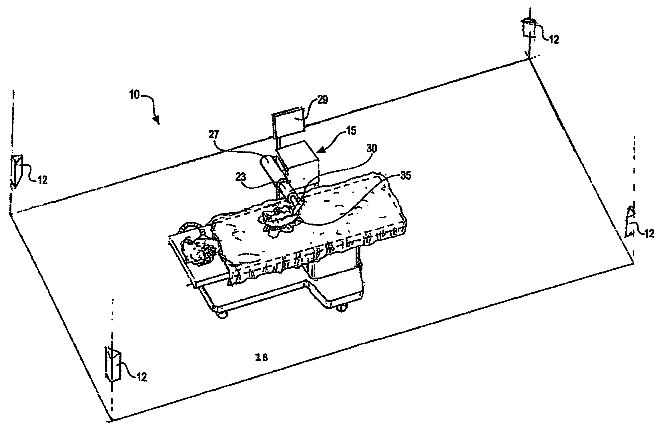
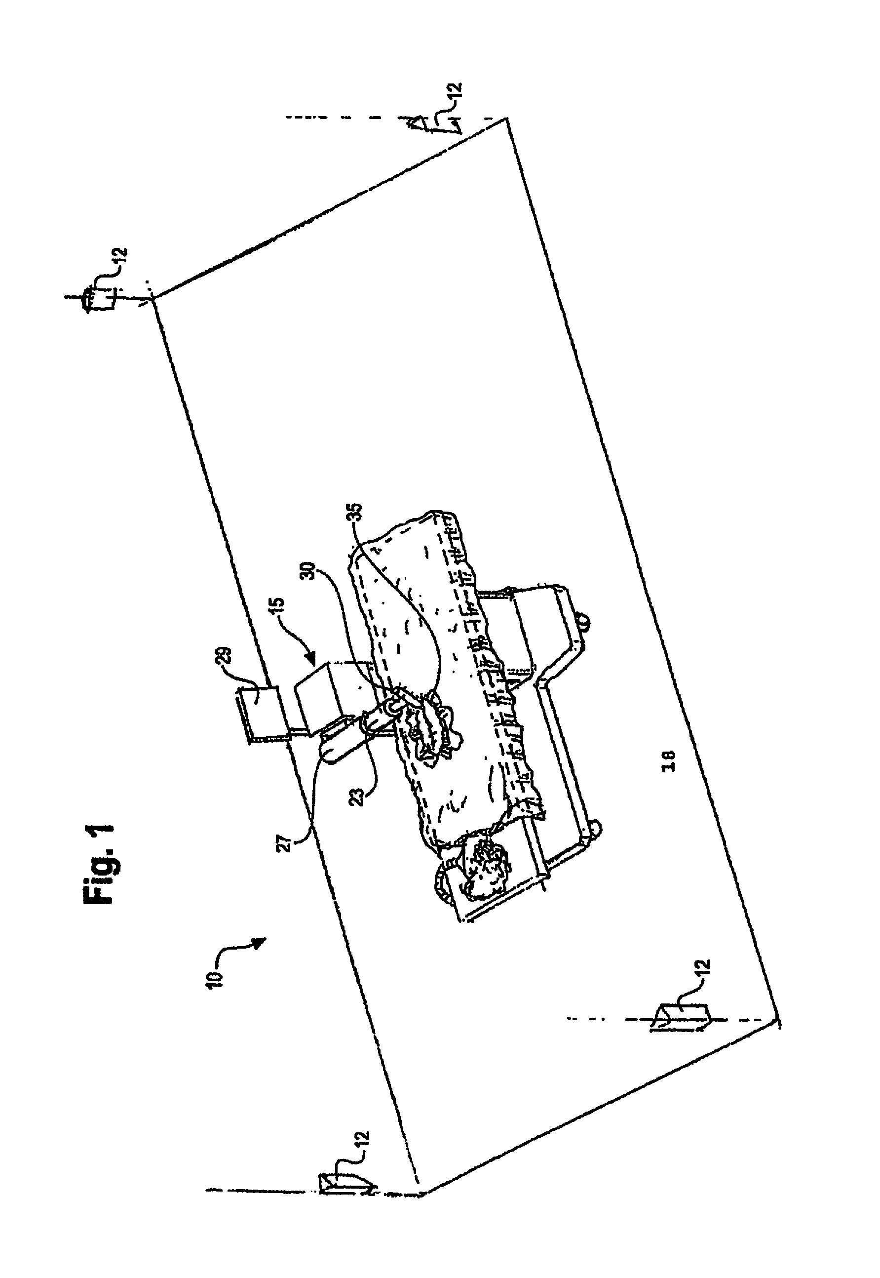
Referring now to FIG. 1, it is seen that in one embodiment of the surgical robot system, a room 10 where an invasive procedure is occurring includes a surgical robot 15, a patient 18 and positioning sensors 12 is provided. Surgical robot 15 includes a display means 29, and a housing 27 which contains a robot arm 23. Robot arm 23 is attached to end effectuator 30. In one embodiment, surgical instrument 35 is removably attached to end effectuator 30. In another embodiment, the end effectuator 30 itself forms an instrument that is used to allow an invasive procedure to take place.
In an embodiment of the invention, prior to an invasive procedure, a 3D image scan is taken of the desired surgical area of patient 18 and sent to a computer (not shown) in communication with surgical robot 15. A physician then programs a desired point of insertion and trajectory for surgical instrument 35 to reach the desired anatomical target in patient 18. This desired point of insertion and trajectory is planned on the 3D image scan which is displayed on display means 29. For example, a physician can plan the desired insertion point and trajectory on a computed tomography (CT) scan of patient 18.
One aspect of the present invention involves the use of a local positioning system (LPS) to track the position of surgical instrument 35. A general description of the LPS system follows. An RF transmitter is affixed at a known location on either the end effectuator 30 or the medical instrument 35. Three transmitters may be evenly radially distributed around the effectuator 30. Three or more RF receivers are positioned at known locations within, for example, the room where the invasive procedure is to take place. Preferably, the RF receivers are not located in the same plane that is parallel to the floor of the room where the procedure is performed.
To calculate the position of the RF transmitter, the time of flight of the RF signal from the RF transmitter to each one of the RF receivers is measured. Because the velocity of the RF signal is known, the time of flight measurements result in at least three distance measurements, one from each RF receiver.
The memory of a control device that performs the time of flight calculations can include, for example, a geometrical description of the location of the RF transmitter with respect to the operative end of the medical instrument 35 or end effectuator 30 that is utilized to perform or assist in performing an invasive procedure. By doing so, the position of the RF transmitter as well as the dimensional profile of the medical instrument or the effectuator element itself can be displayed on a monitor that is viewed by the person performing the invasive procedure. As one example, the end effectuator element 30 can be a tubular element that is positioned at a desired location with respect to, for example, a patient's spine in connection with the performance of a spinal surgery. The tubular element can be aligned with the z axis defined by corresponding robot motor or, for example, can be disposed at an angle relative thereto. In either case, the control device takes the orientation of the tubular element and the position of the RF transmitter into account. The transmitter is affixed at a desired location of the instrument and the control device may be configured to selectively energize the transmitter to cause at least a portion of the instrument to move in a desired direction.
Another aspect of the present invention involves the utilization of a robot that is capable of moving the end effectuator 30 in x, y and z directions that are orthogonal to each other independently of each other or in any combination. For example, the end effectuator 30 can be moved a given distance along the x axis without causing any movement along the y or z axes. The roll, pitch and yaw and the end effectuator 30 also can be selectively controlled. This aspect of the present invention is advantageous because, for example, its use allows invasive medical procedures to take place with a significantly improved accuracy compared to conventional robots that utilize, for example, a six degree of freedom robot arm. A more complete description of these and other aspects of the invention follows.
Referring to FIG. 1, positioning sensors 12 receive RF signals from RF transmitters (not pictured) located within room 10. These RF transmitters are disposed on various points on surgical robot 10 and/or on patient 18. For example, RF transmitters are attached to housing 27, robot arm 23, end effectuator 30 and surgical instrument 35. Positioning sensors 12, which in an exemplary embodiment comprise RF receivers that are in communication with a computer (not pictured), receive the signal from the RF transmitters. Each transmitter transmits on a different frequency so the identity of each transmitter in the room is determinable. The location of the RF transmitters, and consequently the objects to which the transmitters are attached, are calculated by the computer using time of flight algorithms.
The computer (not pictured) is also in communication with surgical robot 15, and moves surgical robot 15 according to the preplanned trajectory entered prior to the procedure. The position of surgical instrument 35 is dynamically updated so that surgical robot 15 is aware of the location of surgical instrument 35 location at all times during the procedure. Consequently, surgical robot 15 can move surgical instrument 35 to the desired position quickly with minimal damage to patient 18 and without any further assistance from a physician unless the physician so desires. Surgical robot 15 can also correct the path if surgical instrument 35 strays from the desired trajectory.
The physician or other user of the system has the option to stop, modify, or manually control the autonomous movement of surgical robot 15. Further, tolerance controls are preprogrammed into surgical robot 15, which adjust the movement of the surgical robot 15 if certain conditions are met. For example, if the surgical robot 15 cannot detect the positions of surgical instrument 35 because of a malfunction in the RF transmitter attached thereto, it will stop movement. Another example is if surgical robot 15 detects a resistance above a tolerance level, then it will stop movement.
In a preferred embodiment of the invention, display means 29 is a monitor attached to surgical robot 15. Alternatively, display means 29 is not attached to surgical robot 15, but is located either within surgical room 10 or in a remote location.
The computer for use in the system (not pictured), can be located within surgical robot 15, or, alternatively, in another location within surgical room 10 or in a remote location. The computer is in conununication with positioning sensors 12 and surgical robot 15.
The surgical robot can also be used with existing guidance systems. Alternative guidance systems are within the scope and spirit of the invention. For instance, an optical tracking system for tracking the location of the surgical device. A commercially available infrared optical tracking system, such as Optotrak (Northern Digital, Waterloo, Ontario, Canada), can be used to track the patient movement and the robot's base location and used with the guidance system. Optical systems require the use of optical markers, which are markers which emit or reflect light, attached to the surgical device. Light emitted from the markers is read by cameras or optical sensors. The location of the object is calculated through triangulation.
Referring now to FIG. 2, it is seen that one embodiment of the surgical robot is shown. The surgical robot includes a base 25 connected to wheels 31. Case 40 is slidably attached to base 25 so that case 40 can slide up and down on a z-axis line perpendicular to the surface on which base 25 sits. Surgical robot also includes a display means 29, and a housing 27 which contains arm 23. Arm 23 is connected to an end effectuator 30. Surgical instrument 35 is removably attached to end effectuator 30.
Surgical instrument 35 can be any instrument used in a medical procedure, both invasive or non-invasive. Surgical instrument 35 may be, for example, a catheter, a probe, a sensor, needle, scalpel forceps, or any other instrument used in a surgical, non-invasive, or diagnostic procedure. Surgical instrument 35 can also be a biological delivery device apparatus, such as a syringe, which can distribute biologically acting compounds throughout the body. The plunger of the syringe may be manually pressed by a user or automatically compressed by the system once the desired target is reached.
The surgical robot is moveable in a plurality of axes in order to improve the ability to precisely reach a target location. The robot moves on a Cartesian positioning system, that is, movements in different axes can occur relatively independently instead of at the end of a series of joints.
Referring now to FIGS. 3A and 3B, the movement of case 40 relative to base 25 is shown. Case 40 can raise and lower relative to the base 25 in the z-axis direction.
In a preferred embodiment of the invention, housing 27 is attached to case 40 and moves in the z-direction with case 40 when case 40 is raised and lowered. Consequently, arm 23, end effectuator 30 and surgical instrument 35 move with case 40 as case 40 is raised and lowered relative to base 25.
Referring now to FIG. 4, housing 27 is slidably attached to case 40 so that it can extend and retract in a x-axis direction relative to case 40 and perpendicular to the direction case 40 moves relative to base 25. Consequently, arm 23, end effectuator 30 and surgical instrument 35 move with housing 27 as housing 27 is extended and retracted relative to case 40.
Referring now to FIGS. 5A and 5B, the extension of arm 23 along the y-axis is shown. Arm 23 is extendable on the y-axis relative to case 40, base 25, and housing 27. Consequently, end effectuator 30 and surgical instrument 35 move with arm 23 as arm 23 is extended and retracted relative to housing 27. In an embodiment of the invention, arm 23 is attached to a low profile rail system (not shown) which is encased by housing 27.
Referring now to FIGS. 6, 7 and 8, the movement of the end effectuator 30 is shown. FIG. 6 shows end effectuator 30 is capable of rotating along the x axis. FIG. 7 shows end effectuator 30 is capable of rotating along the y-axis. FIG. 8 shows end effectuator 30 is capable of raising and lowering surgical instrument 35 on the z axis.
Referring now to FIG. 9, a system diagram of the positioning sensors 110, computer 100, and RF transmitters 120 is provided. Computer 100 is in communication with positioning sensors 110. In operation, RF transmitters 120 are attached to various points on the surgical robot. RF transmitters 120 may also be attached to various points on or around the anatomical target. Computer 100 sends a signal through a wired connection to RF transmitters 120, prompting RF transmitters 120 to transmit RF signals. The RF signals are read by positioning sensors 110. Positioning sensors 110 are in communication with computer 100, which calculates the location of the positions of all the RF sensors based on time-of-flight information received from the positioning sensors 110. Computer 100 dynamically updates the calculated location of the surgical device being used in the procedure, which is displayed to the user.
Alternatively, computer 100 can be wirelessly connected to RF transmitters 120.
Referring now to FIG. 10, a system diagram of computer 100, display 150, user input 170, and motors 160 is provided. Motors 160 are installed in the surgical robot and control the movement of the surgical robot as described above. Computer 100, which dynamically updates the location of the surgical device being used in the procedure, sends the appropriate signals to the motors 160 so that surgical robot reacts accordingly in response to information received by computer 100. For example, computer 100 prompts motors 160 to move the surgical device along a preplanned trajectory.
The user uses input 170 to plan the trajectory of the desired navigation prior to the invasive procedure. If the user wants to make changes in the invasive procedure after it has commenced, he can use user input 170 to make the desired changes. Computer 100 will then send the appropriate signals to motors 160 in response to the user input.
In a preferred embodiment of the invention, motors 160 are pulse motors providing direct drive, or driving a belt drive and pulley combination attached to the surgical instrument used in the procedure. Alternatively, motors 160 are pulse motors and are attached to a belt drive rack-and-pinion system, or similar power transmission components.
Referring now to FIG. 11, a flow chart diagram for general operation of the robot according to an embodiment of the invention is shown.
At step 210, the local positioning system (LPS) establishes a spatial coordinate measuring system for the room where the invasive procedure is to occur; in other words, the LPS is calibrated. In order to calibrate the LPS, a mechanical fixture that includes a plurality of calibrating transmitters attached thereto is placed within the room where positioning sensors are located. At least three calibrating transmitters are required, but any number of calibrating transmitters above three is within the scope of the invention. Also, at least three positioning sensors are required, but any number of positioning sensors above three is also within the scope of the invention, and the accuracy of the system is increased with the addition of more positioning sensors.
The distance between each of the calibrating transmitters relative to each other is measured prior to calibration step 210. Each calibrating transmitter transmits RF signals on a different frequency so the positioning sensors can determine which transmitter emitted a particular RF signal. The signal of each of these transmitters is received by positioning sensors. Since the distance between each of the calibrating transmitters is known, and the sensors can identify the signals from each of the calibrating transmitters based on the known frequency, the positioning sensors are able to calculate, using time of flight calculation, the spatial distance of each of the positioning sensors relative to each other. The system is now calibrated. As a result, the positioning sensors can now determine the spatial position of any new RF transmitter introduced into the room relative to the positioning sensors.
At step 220, a 3D anatomical image scan, such as a CT scan, is taken of the anatomical target. Any 3D anatomical image scan may be used with the surgical robot and is within the scope of the present invention.
At step 230, the positions of the RF transmitters tracking the anatomical target are read by positioning sensors. These transmitters identify the initial position of the anatomical target and any changes in position during the procedure.
If any RF transmitters must transmit through a medium that changes the RF signal characteristics, then the system will compensate for these changes when determining the transmitter's position.
At step 240, the positions of the transmitters on the anatomy are calibrated relative to the LPS coordinate system. In other words, the LPS provides a reference system, and the location of the anatomical target is calculated relative to the LPS coordinates. To calibrate the anatomy relative to the LPS, the positions of transmitters affixed to the anatomical target are recorded at the same time as positions of temporary transmitters on precisely known landmarks on the anatomy that can also be identified on the anatomical image. This calculation is performed by a computer.
At step 250, the positions of the RF transmitters that track the anatomical target are read. Since the locations of the transmitters on the anatomical target have already been calibrated, the system can easily determine if there has been any change in position of the anatomical target.
At step 260, the positions of the transmitters on the surgical instrument are read. The transmitters may be located on the surgical instrument itself, and/or there may be transmitters attached to various points of the surgical robot.
In an embodiment of the invention, the surgical robot also includes a plurality of position encoders attached thereto that help determine the position of the surgical instrument. Position encoders are devices used to generate an electronic signal that indicates a position or movement relative to a reference position. There are many ways to generate a position signal, including for example, magnetic sensors, capacitive sensors, and optical sensors.
Position data read from the position encoders may be used to determine the position of the surgical instrument used in the procedure, and may be redundant of position data calculated from RF transmitters located on the surgical instrument. Therefore, position data from the position encoders may be used to double-check the position being read from the LPS.
At step 270, the coordinates of the positions of the transmitters on the surgical instrument, and/or the positions read from the position encoders, is calibrated relative to the anatomical coordinate system. In other words, the position data of the surgical instrument is synchronized into the same coordinate system as the anatomy. This calculation is performed automatically by the computer since the positions of the transmitters on the anatomical target and the positions of the transmitters on the surgical instrument are in the same coordinate system and the positions of the transmitters on the anatomical target are already calibrated relative to the anatomy.
At step 280, the computer superimposes a representation of the location calculated in step 270 of the surgical device on the 3D anatomical image of the patient taken in step 220. The superimposed image is displayed to the user.
At step 290, the computer sends the appropriate signals to the motors to drive the surgical robot. If the user preprogrammed a trajectory, then the robot is driven so that the surgical instrument follows the preprogrammed trajectory if there is no further input from the user. If there is user input, then the computer drives the robot in response to the user input.
At step 295, the computer determines whether the procedure has been completed. If the procedure has not been completed, then the process beginning at step 250 is repeated.
At any time during the procedure, certain fault conditions may cause the computer to interrupt the program and respond accordingly. For instance, if the signal from the RF transmitters cannot be read, then the computer may be programmed to stop the movement of the robot or remove the surgical instrument from the patient. Another example of a fault condition is if the robot encounters a resistance above a preprogrammed tolerance level. Another example of a fault condition is if the RF transmitters on the anatomical target indicate that the location of the anatomical target has shifted relative to the RF transmitters--this spatial relationship should be fixed. In this case, one indicator that the anatomical target location has shifted relative to the transmitters is if the computer calculates that the surgical instrument appears to be inside bone when no drilling or penetration is actually occurring.
The proper response to each condition may be programmed into the, or a specific response may be user-initiated as well. For example, the computer may determine that in response to an anatomy shift, the anatomy would have to be recalibrated, and the process beginning at step 230 should be repeated. Alternatively, a fault condition may require the flowchart to repeat from step 210. Another alternative is the user may decide that recalibration from step 230 is desired, and initiate that step himself.
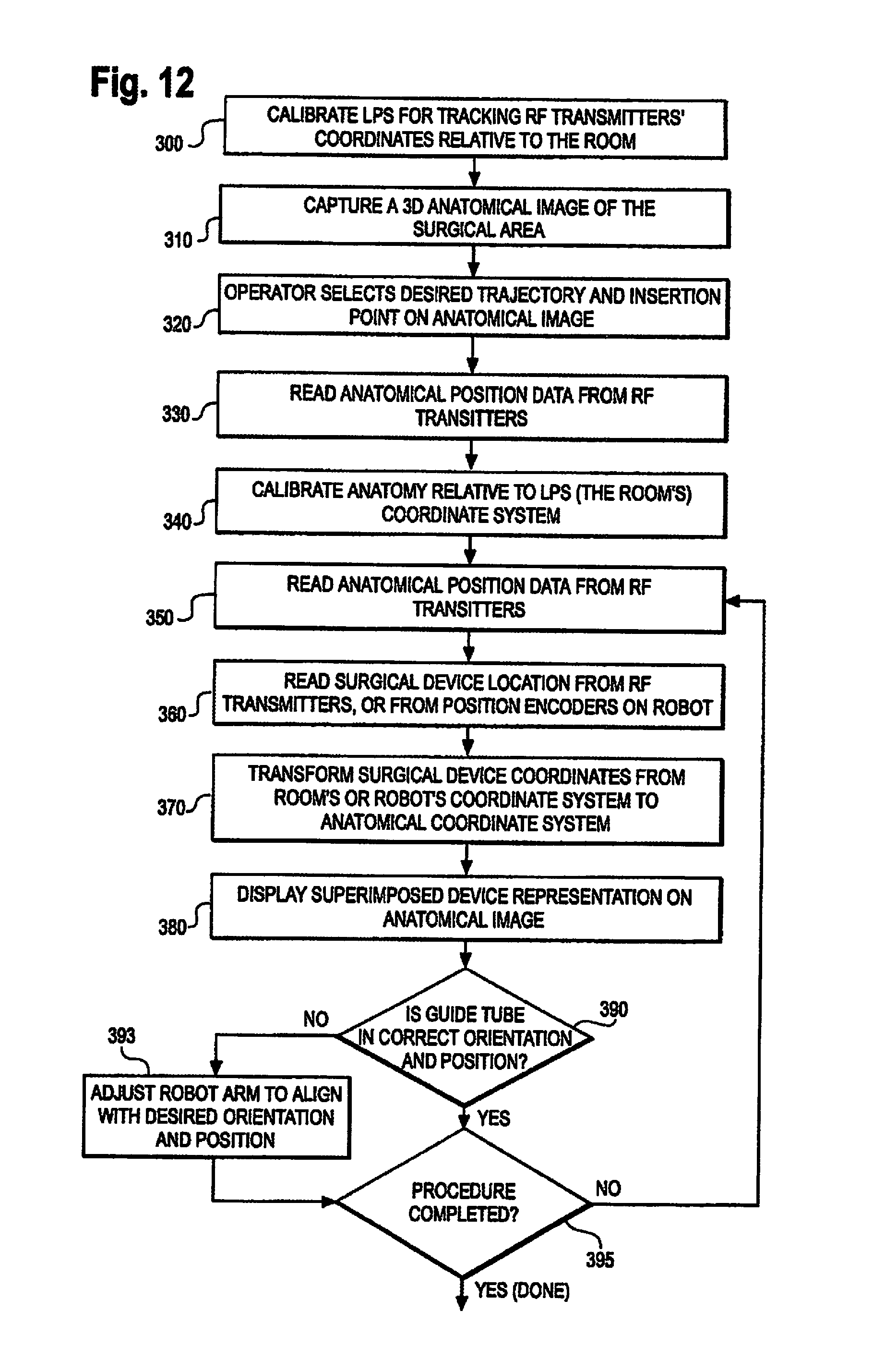
Referring now to FIG. 12, a flow chart diagram for a closed screw/needle insertion procedure according to an embodiment of the invention is shown. In a closed pedicle screw insertion procedure, the robot holds a guide tube adjacent to the patient in the correct angular orientation and at the point where a pedicle screw is to be inserted through the tissue and into the bone of the patient.
The distance between each of the calibrating transmitters relative to each other is measured prior to calibration step 300. Each calibrating transmitter transmits RF signals on a different frequency so the positioning sensors can determine which transmitter emitted a particular RF signal. The signal of each of these transmitters is received by positioning sensors. Since the distance between each of the calibrating transmitters is known, and the sensors can identify the signals from each of the calibrating transmitters based on the known frequency, the positioning sensors are able to calculate, using time of flight calculation, the spatial distance of each of the positioning sensors relative to each other. The system is now calibrated. As a result, the positioning sensors can now determine the spatial position of any new RF transmitter introduced into the room relative to the positioning sensors.
At step 310, a 3D anatomical image scan, such as a CT scan, is taken of the anatomical target. Any 3D anatomical image scan may be used with the surgical robot and is within the scope of the present invention.
At step 320, the operator selects a desired trajectory and insertion point of the surgical instrument on the anatomical image captured at step 310. This desired trajectory and insertion point is programmed into the computer so that the robot can drive a guide tube automatically to follow the trajectory.
At step 330, the positions of the RF transmitters tracking the anatomical target are read by positioning sensors. These transmitters identify the initial position of the anatomical target and any changes in position during the procedure.
If any RF transmitters must transmit through a medium that changes the RF signal characteristics, then the system will compensate for these changes when determining the transmitter's position.
At step 340, the positions of the transmitters on the anatomy are calibrated relative to the LPS coordinate system. In other words, the LPS provides a reference system, and the location of the anatomical target is calculated relative to the LPS coordinates. To calibrate the anatomy relative to the LPS, the positions of transmitters affixed to the anatomical target are recorded at the same time as positions of temporary transmitters on precisely known landmarks on the anatomy that can also be identified on the anatomical image. This calculation is performed by a computer.
At step 350, the positions of the RF transmitters that track the anatomical target are read. Since the locations of the transmitters on the anatomical target have already been calibrated, the system can easily determine if there has been any change in position of the anatomical target.
At step 360, the positions of the transmitters on the surgical instrument are read. The transmitters may be located on the surgical instrument itself, and/or there may be transmitters attached to various points of the surgical robot.
In an embodiment of the invention, the surgical robot also includes a plurality of position encoders attached thereto that help determine the position of the surgical instrument. Position encoders are devices used to generate an electronic signal that indicates a position or movement relative to a reference position. There are many ways to generate a position signal, including for example, magnetic sensors, capacitive sensors, and optical sensors.
Position data read from the position encoders may be used to determine the position of the surgical instrument used in the procedure, and may be redundant of position data calculated from RF transmitters located on the surgical instrument. Therefore, position data from the position encoders may be used to double-check the position being read from the LPS.
At step 370, the coordinates of the positions of the transmitters on the surgical instrument, and/or the positions read from the position encoders, is calibrated relative to the anatomical coordinate system. In other words, the position data of the surgical instrument is synchronized into the same coordinate system as the anatomy. This calculation is performed automatically by the computer since the positions of the transmitters on the anatomical target and the positions of the transmitters on the surgical instrument are in the same coordinate system and the positions of the transmitters on the anatomical target are already calibrated relative to the anatomy.
At step 380, the computer superimposes a representation of the location calculated in step 370 of the surgical device on the 3D anatomical image of the patient taken in step 310. The superimposed image is displayed to the user.
At step 390, the computer determines whether the guide tube is in the correct orientation and position to follow the trajectory planned at step 320. If it is not, then step 393 is reached. If it is in the correct orientation and position to follow the trajectory, then step 395 is reached.
At step 393, the computer determines what adjustments it needs to make in order to make the guide tube follow the preplanned trajectory. The computer sends the appropriate signals to drive the motors in order to correct the movement of the guide tube.
At step 395, the computer determines whether the procedure has been completed. If the procedure has not been completed, then the process beginning at step 350 is repeated.
At any time during the procedure, certain fault conditions may cause the computer to interrupt the program and respond accordingly. For instance, if the signal from the RF transmitters cannot be read, then the computer may be programmed to stop the movement of the robot or lift the guide tube away from the patient. Another example of a fault condition is if the robot encounters a resistance above a preprogrammed tolerance level. Another example of a fault condition is if the RF transmitters on the anatomical target indicate that the location of the anatomical target has shifted relative to the RF transmitters--this spatial relationship should be fixed. In this case, one indicator that the anatomical target location has shifted relative to the transmitters is if the computer calculates that the surgical instrument appears to be inside bone when no drilling or penetration is actually occurring.
The proper response to each condition may be programmed into the, or a specific response may be user-initiated as well. For example, the computer may determine that in response to an anatomy shift, the anatomy would have to be recalibrated, and the process beginning at step 330 should be repeated. Alternatively, a fault condition may require the flowchart to repeat from step 300. Another alternative is the user may decide that recalibration from step 330 is desired, and initiate that step himself.
Referring now to FIG. 13, a flow chart diagram for a safe zone surgical procedure according to an embodiment of the invention is shown. In a safe zone surgical procedure, there is a defined "safe zone" around the surgical area within which the surgical device must stay. The physician manually controls the surgical device that is attached to the end effectuator of the surgical robot. If the physician moves the surgical device outside of the safe zone, then the surgical robot stiffens the arm so that the physician cannot move the instrument in any direction that The distance between each of the calibrating transmitters relative to each other is would move the surgical device outside the safe zone.
The distance between each of the calibrating transmitters relative to each other is measured prior to calibration step 400. Each calibrating transmitter transmits RF signals on a different frequency so the positioning sensors can determine which transmitter emitted a particular RF signal. The signal of each of these transmitters is received by positioning sensors. Since the distance between each of the calibrating transmitters is known, and the sensors can identify the signals from each of the calibrating transmitters based on the known frequency, the positioning sensors are able to calculate, using time of flight calculation, the spatial distance of each of the positioning sensors relative to each other. The system is now calibrated. As a result, the positioning sensors can now determine the spatial position of any new RF transmitter introduced into the room relative to the positioning sensors.
At step 410, a 3D anatomical image scan, such as a CT scan, is taken of the anatomical target. Any 3D anatomical image scan may be used with the surgical robot and is within the scope of the present invention.
At step 420, the operator inputs a desired safe zone on the anatomical image taken in step 410. In an embodiment of the invention, the operator uses an input to the computer to draw a safe zone on a CT scan taken of the patient in step 410.
At step 430, the positions of the RF transmitters tracking the anatomical target are read by positioning sensors. These transmitters identify the initial position of the anatomical target and any changes in position during the procedure.
If any RF transmitters must transmit through a medium that changes the RF signal characteristics, then the system will compensate for these changes when determining the transmitter's position.
At step 440, the positions of the transmitters on the anatomy are calibrated relative to the LPS coordinate system. In other words, the LPS provides a reference system, and the location of the anatomical target is calculated relative to the LPS coordinates. To calibrate the anatomy relative to the LPS, the positions of transmitters affixed to the anatomical target are recorded at the same time as positions of temporary transmitters on precisely known landmarks on the anatomy that can also be identified on the anatomical image. This calculation is performed by a computer.
At step 450, the positions of the RF transmitters that track the anatomical target are read. Since the locations of the transmitters on the anatomical target have already been calibrated, the system can easily determine if there has been any change in position of the anatomical target.
At step 460, the positions of the transmitters on the surgical instrument are read. The transmitters may be located on the surgical instrument itself; and/or there may be transmitters attached to various points of the surgical robot.
In an embodiment of the invention, the surgical robot also includes a plurality of position encoders attached thereto that help determine the position of the surgical instrument. Position encoders are devices used to generate an electronic signal that indicates a position or movement relative to a reference position. There are many ways to generate a position signal, including for example, magnetic sensors, capacitive sensors, and optical sensors.
Position data read from the position encoders may be used to determine the position of the surgical instrument used in the procedure, and may be redundant of position data calculated from RF transmitters located on the surgical instrument. Therefore, position data from the position encoders may be used to double-check the position being read from the LPS.
At step 470, the coordinates of the positions of the transmitters on the surgical instrument, and/or the positions read from the position encoders, is calibrated relative to the anatomical coordinate system. In other words, the position data of the surgical instrument is synchronized into the same coordinate system as the anatomy. This calculation is performed automatically by the computer since the positions of the transmitters on the anatomical target and the positions of the transmitters on the surgical instrument are in the same coordinate system and the positions of the transmitters on the anatomical target are already calibrated relative to the anatomy.
At step 480, the computer superimposes a representation of the location calculated in step 470 of the surgical device on the 3D anatomical image of the patient taken in step 410. The superimposed image is displayed to the user.
At step 490, the computer determines whether the surgical device attached to the end effectuator of the surgical robot is within a specified range of the safe zone boundary, for example, within 1 millimeter of reaching the safe zone boundary. If the end effectuator is almost to the boundary, then step 493 is reached. If it is well within the safe zone boundary, then step 495 is reached.
At step 493, the computer stiffens the arm of the surgical robot in any direction that would allow the user to move the surgical device closer to the safe zone boundary.
At step 495, the computer determines whether the procedure has been completed. If the procedure has not been completed, then the process beginning at step 450 is repeated.
At any time during the procedure, certain fault conditions may cause the computer to interrupt the program and respond accordingly. For instance, if the signal from the RF transmitters cannot be read, then the computer may be programmed to stop the movement of the robot or remove the surgical instrument from the patient. Another example of a fault condition is if the robot encounters a resistance above a preprogrammed tolerance level. Another example of a fault condition is if the RF transmitters on the anatomical target indicate that the location of the anatomical target has shifted relative to the RF transmitters--this spatial relationship should be fixed. In this case, one indicator that the anatomical target location has shifted relative to the transmitters is if the computer calculates that the surgical instrument appears to be inside bone when no drilling or penetration is actually occurring.
The proper response to each condition may be programmed into the, or a specific response may be user-initiated as well. For example, the computer may determine that in response to an anatomy shift, the anatomy would have to be recalibrated, and the process beginning at step 430 should be repeated. Alternatively, a fault condition may require the flowchart to repeat from step 400. Another alternative is the user may decide that recalibration from step 430 is desired, and initiate that step himself.
Referring now to FIG. 14, a flow chart diagram for a flexible catheter or wire insertion procedure according to an embodiment of the invention is shown. Catheters are used in a variety of medical procedures to deliver medicaments to a specific site in a patient's body. Often, delivery to a specific location is needed so a targeted diseased area can then be treated. Sometimes instead of inserting the catheter directly, a flexible wire is first inserted, over which the flexible catheter can be slid.
The distance between each of the calibrating transmitters relative to each other is measured prior to calibration step 500. Each calibrating transmitter transmits RF signals on a different frequency so the positioning sensors can determine which transmitter emitted a particular RF signal. The signal of each of these transmitters is received by positioning sensors. Since the distance between each of the calibrating transmitters is known, and the sensors can identify the signals from each of the calibrating transmitters based on the known frequency, the positioning sensors are able to calculate, using time of flight calculation, the spatial distance of each of the positioning sensors relative to each other. The system is now calibrated. As a result, the positioning sensors can now determine the spatial position of any new RF transmitter introduced into the room relative to the positioning sensors.
At step 510, reference needles that contain the RF transmitters are inserted into the body. The purpose of these needles is to track movement of key regions of soft tissue that will deform during the procedure or with movement of the patient.
Step 520, a 3D anatomical image scan, such as a CT scan, is taken of the anatomical target. Any 3D anatomical image scan may be used with the surgical robot and is within the scope of the present invention. The anatomical image capture area includes the tips of the reference needles so that their transmitters' positions can be determined relative to the anatomy
At step 530, the RF signals from the catheter tip and reference needles are read.
At step 540, the position of the catheter tip is calculated. Because the position of the catheter tip relative to the reference needles and the positions of the reference needles relative to the anatomy are known, the computer can calculate the position of the catheter tip relative to the anatomy.
At step 550, the superimposed catheter tip and the shaft representation is displayed on the anatomical image taken in step 520.
At step 560, the computer determines whether the catheter tip is advancing toward the anatomical target. If it is not moving to the anatomical target, then step 563 is reached. If it is correctly moving, then step 570 is reached.
At step 563, the robot arm is adjusted to guide the catheter tip in the desired direction. If the anatomy needs to be calibrated, then the process beginning at step 520 is repeated. If the anatomy does not need to be recalibrated, then the process beginning at step 540 is repeated.
At step 570, the computer determines whether the procedure has been completed. If the procedure has not been completed, then the process beginning at step 540 is repeated.
At any time during the procedure, certain fault conditions may cause the computer to interrupt the program and respond accordingly. For instance, if the signal from the RF transmitters cannot be read, then the computer may be programmed to stop the movement of the robot or remove the flexible catheter from the patient. Another example of a fault condition is if the robot encounters a resistance above a preprogrammed tolerance level. Another example of a fault condition is if the RF transmitters on the anatomical target indicate that the location of the anatomical target has shifted relative to the RF transmitters--this spatial relationship should be fixed. In this case, one indicator that the anatomical target location has shifted relative to the transmitters is if the computer calculates that the surgical instrument appears to be inside bone when no drilling or penetration is actually occurring.
The proper response to each condition may be programmed into the, or a specific response may be user-initiated as well. For example, the computer may determine that in response to an anatomy shift, the anatomy would have to be recalibrated, and the process beginning at step 520 should be repeated. Alternatively, a fault condition may require the flowchart to repeat from step 500. Another alternative is the user may decide that recalibration from step 520 is desired, and initiate that step himself.
Referring now to FIGS. 15A & 15B, screenshots of software for use with an embodiment of the invention is provided. The software provides the method to select the target area of surgery, plan the surgical path, check the planned trajectory of the surgical path, synchronize the medical images to the positioning system and precisely control the positioning system during surgery. The surgical positioning system and navigation software includes an optical guidance system or RF Local Positioning System (RF-LPS), which are in communication with the positioning system.
FIG. 15A shows a screen shot 600 of the selection step for a user using the software program. Screen shot 600 includes windows 615, 625, and 635, which show a 3D anatomical image of surgical target 630 on different planes. In this step, the user selects the appropriate 3D image corresponding to anatomical location of where the procedure will occur. The user uses a graphic control to change the perspective of the image in order to more easily view the image from different angles. The user can view the surgical target 630 separate coordinate views for each of the X, Y and Z axis for each anatomical location in the database in each window 615, 625 and 635, respectively.
After selecting the desired 3D image of the surgical target 630, the user will plan the appropriate trajectory on the selected image. An input control is used with the software in order to plan the trajectory of the surgical instrument. In one embodiment of the invention, the input control is in the shape of a biopsy needle for which the user can plan a trajectory.
FIG. 15B shows a screen shot 650 during the medical procedure. The user can still view the anatomical target 630 in different x, y and z coordinate views on windows 615, 625, and 635.
In screen shot 650, the user can see the planned trajectory line 670 in multiple windows 615 and 625. The actual trajectory and location of the surgical instrument 660 is superimposed on the image. The actual trajectory and location of the surgical instrument 660 is dynamically updated and displayed.
As described earlier, the surgical robot can be used with alternate guidance systems other than an LPS. One embodiment of the invention contemplates the use of a calibration frame for use with the guidance system, as shown in FIG. 16. A calibration frame 700 can be used in connection with many invasive procedures; for example, it can be used in thoracolumbar pedicle screw insertion in order to help achieve a more accurate trajectory position.
The use of the calibration frame 700 simplifies the calibration procedure. The calibration frame 700 comprises a combination of radio-opaque markers 730 and infrared, or "active", markers 720. The radio-opaque markers 730 are located within the CT scan region 710, and the active markers are located outside of the CT scan region 710. A surgical field 750, the area where the invasive procedure will occur, is located within the perimeter created by radio-opaque markers 730. The actual distances of the radio-opaque and active markers relative to each other is measured from a high-precision laser scan of the calibration frame. Further, active markers are also placed on the robot (not shown).
The calibration frame 700 is mounted on the patient's skin before surgery/biopsy, and will stay mounted during the entire procedure. Surgery/biopsy takes place through the center of the frame.
When the region of the plate with the radio-opaque markers 730 is scanned intraoperatively or prior to surgery in, for example, a computed tomography (CT) scanner, the CT scan contains both the medical images of the patient's bony anatomy and spherical representations of the radio-opaque markers 730. Software is used to determine the locations of the centers of the spheres relative to the trajectories defined by the surgeon on the medical images.
Because the system knows the positions of the trajectories relative to the radio-opaque markers 730, the positions of the radio-opaque markers 730 relative to the active markers 720, and the positions of the active markers 720 on the calibration frame 700 relative to the active markers on the robot (not shown), the system has all information necessary to position the robot's end effector relative to the defined trajectories.
One aspect of the software disclosed herein is a unique algorithm for locating the center of the above-described spheres that takes advantage of the fact that a CT scan consists of slices typically spaced 1.5 mm or more apart in the z direction but sampled with about 0.3 min resolution in the x and y directions. Since the diameter of the radio-opaque spheres is several times larger than this slice spacing, different z slices of the sphere will appear as circles of different diameters on each successive xy planar slice. Since the diameter of the sphere is defined beforehand, the necessary z position of the center of the sphere relative to the slices can be calculated that achieves the given set of circles of various diameters. This algorithm provides, for example, the center of a large sphere more precisely than other methods could find the center of a sphere that is closer in diameter to the slice thickness.
To provide further illustration of how the calibration plate works according to an embodiment of the invention, the steps of a closed screw/needle insertion procedure utilizing a calibration frame is described. First, a calibration frame 700 is attached to the patient's skin in the region at which surgery/biopsy is to take place. Next, the patient receives a CT scan either supine or prone, whichever positioning orients the calibration frame upward. Thereafter, the surgeon manipulates three planar views of the patient's CT images with rotations and translations. The surgeon then draws trajectories on the images that define the desired position and strike angle of the end effector.
The robot then will move to the desired position. If forceful resistance beyond a pre-set tolerance is exceeded, the robot will halt. The robot holds the guide tube at the desired position and strike angle to allow the surgeon to insert a screw or needle. If tissues move in response to applied force or due to breathing, the movement will be tracked by optical markers and the robot's position will automatically be adjusted.
As a further illustration of a procedure using an alternate guidance system, the steps of an open screw insertion procedure utilizing an optical guidance system is described. After surgical exposure, a small tree of optical markers is attached to a bony prominence in the area of interest. Calibration procedures standard for image guidance are used to establish the anatomy relative to the optical tracking system and medical images.
The surgeon manipulates three planar views of the patient's CT images with rotations and translations. The surgeon then draws trajectories on the images that define the desired position and strike angle of the end effector.
The robot moves to the desired position. If forceful resistance beyond a pre-set tolerance is exceeded, the robot will halt. The robot holds the guide tube at the desired position and strike angle to allow the surgeon to insert a screw. If tissues move in response to applied force or due to breathing, the movement will be tracked by optical markers and the robot's position will automatically be adjusted.
If desired, two or more RF transmitters can be affixed to the medical instrument at certain locations thereof, the two or more RF transmitters being selectively energizable to generate forces that are applied to the medical instrument and cause at least a portion of it to move in a desired direction. Similarly, at least three RF transmitters can be affixed to the medical instrument at desired locations thereof, if desired, the three RF transmitters being selectively energizable to generate forces that are applied to the medical instrument cause at least a portion of it to move in a desired direction. The three RF transmitters can be evenly radially distributed around the medical instrument, at a distal end of the medical instrument and/or on a leading edge of the medical instrument. From the foregoing it will be observed that numerous modifications and variations can be effectuated without departing form the true spirit and scope of the novel concepts of the present invention. It is to be understood that no limitation with respect to the specific embodiments illustrated is intended or should be inferred. The disclosure is intended to cover by the appended claims all such modifications as fall within the scope of the claims.
* * * * *
D00000
D00001
D00002
D00003
D00004
D00005
D00006
D00007
D00008
D00009
D00010
D00011
XML
uspto.report is an independent third-party trademark research tool that is not affiliated, endorsed, or sponsored by the United States Patent and Trademark Office (USPTO) or any other governmental organization. The information provided by uspto.report is based on publicly available data at the time of writing and is intended for informational purposes only.
While we strive to provide accurate and up-to-date information, we do not guarantee the accuracy, completeness, reliability, or suitability of the information displayed on this site. The use of this site is at your own risk. Any reliance you place on such information is therefore strictly at your own risk.
All official trademark data, including owner information, should be verified by visiting the official USPTO website at www.uspto.gov. This site is not intended to replace professional legal advice and should not be used as a substitute for consulting with a legal professional who is knowledgeable about trademark law.