Constrained motion bone screw assembly
Chao , et al. J
U.S. patent number 10,172,648 [Application Number 15/711,380] was granted by the patent office on 2019-01-08 for constrained motion bone screw assembly. This patent grant is currently assigned to Medos International Sarl. The grantee listed for this patent is Medos International Sarl. Invention is credited to Randal Betz, Nam T. Chao, Jerold P. Gurley, Peter O. Newton, Ronald Sacher, Simon Siu.


View All Diagrams
| United States Patent | 10,172,648 |
| Chao , et al. | January 8, 2019 |
Constrained motion bone screw assembly
Abstract
A bone screw assembly includes an anchor portion and a head portion, such as a rod-receiving portion, movably mounted to the anchor portion to allow for controlled angulation between the anchor portion and the head portion. The anchor portion is pivotable in one or more selected directions about an axis relative to the head portion. A restriction member, which may be a rod seat, prevents the anchor portion from pivoting in one or more different directions about another axis relative to the head portion and/or a spinal fixation element received in the head portion. The restriction member may be inserted in the head portion to control direction that the anchor portion pivots relative to the head portion. The restriction member may also serve as a compression member and/or rod seat for seating a spinal rod coupled to the bone screw assembly.
| Inventors: | Chao; Nam T. (Marlborough, MA), Siu; Simon (Quincy, MA), Sacher; Ronald (Boca Raton, FL), Gurley; Jerold P. (Middleburg Heights, OH), Betz; Randal (Ocean City, NJ), Newton; Peter O. (San Anselmo, CA) | ||||||||||
|---|---|---|---|---|---|---|---|---|---|---|---|
| Applicant: |
|
||||||||||
| Assignee: | Medos International Sarl (Le
Locle, CH) |
||||||||||
| Family ID: | 36945059 | ||||||||||
| Appl. No.: | 15/711,380 | ||||||||||
| Filed: | September 21, 2017 |
Prior Publication Data
| Document Identifier | Publication Date | |
|---|---|---|
| US 20180008319 A1 | Jan 11, 2018 | |
Related U.S. Patent Documents
| Application Number | Filing Date | Patent Number | Issue Date | ||
|---|---|---|---|---|---|
| 14754259 | Jun 29, 2015 | 9795416 | |||
| 13087777 | Aug 4, 2015 | 9095379 | |||
| 11073325 | May 31, 2011 | 7951172 | |||
| Current U.S. Class: | 1/1 |
| Current CPC Class: | A61B 17/7038 (20130101); A61B 17/7037 (20130101); A61B 17/704 (20130101); A61B 17/7041 (20130101); A61B 17/7032 (20130101) |
| Current International Class: | A61B 17/70 (20060101) |
References Cited [Referenced By]
U.S. Patent Documents
| 410780 | September 1889 | Cahn |
| 445513 | January 1891 | Powell |
| 1116532 | November 1914 | Armstrong |
| 1470313 | October 1923 | Woolen |
| 1628144 | May 1927 | Herrmann |
| 1709766 | April 1929 | Bolton |
| 1889330 | November 1932 | Humes et al. |
| 1925385 | September 1933 | Humes et al. |
| 2113246 | April 1938 | Wappler |
| 2248054 | July 1941 | Becker |
| 2248057 | July 1941 | Bond |
| 2291413 | July 1942 | Siebrandt |
| 2370407 | February 1945 | McCartney |
| 2669896 | February 1954 | Clough |
| 2800820 | July 1957 | Retterath |
| 2952285 | September 1960 | Roosl |
| 3604487 | September 1971 | Gilbert |
| 3960147 | June 1976 | Murray |
| 4237875 | December 1980 | Termanini |
| 4271836 | June 1981 | Bacal et al. |
| 4363250 | December 1982 | Suga |
| 4411259 | October 1983 | Drummond |
| 4445513 | May 1984 | Ulrich et al. |
| 4655223 | April 1987 | Kim |
| 4733657 | March 1988 | Kluger |
| 4743260 | May 1988 | Burton |
| 4809695 | March 1989 | Gwathmey et al. |
| 4887596 | December 1989 | Sherman |
| 4896661 | January 1990 | Bogert et al. |
| 4950269 | August 1990 | Gaines, Jr. |
| 4957495 | September 1990 | Kluger |
| 4987892 | January 1991 | Krag et al. |
| 5005562 | April 1991 | Cotrel |
| 5014407 | May 1991 | Boughten et al. |
| 5020519 | June 1991 | Hayes et al. |
| 5067955 | November 1991 | Cotrel |
| 5092866 | March 1992 | Breard et al. |
| 5120171 | June 1992 | Lasner |
| 5176678 | January 1993 | Tsou |
| 5176680 | January 1993 | Vignaud et al. |
| 5181971 | January 1993 | Ohtsuka |
| 5190543 | March 1993 | Schlapfer |
| 5219349 | June 1993 | Krag et al. |
| 5226766 | July 1993 | Lasner |
| 5261913 | November 1993 | Marnay |
| 5263939 | November 1993 | Wortrich |
| 5282801 | February 1994 | Sherman |
| 5282863 | February 1994 | Burton |
| D346217 | April 1994 | Sparker et al. |
| 5306248 | April 1994 | Barrington |
| 5330474 | July 1994 | Lin |
| 5334203 | August 1994 | Wagner |
| 5360431 | November 1994 | Puno et al. |
| 5364397 | November 1994 | Hayes et al. |
| 5385565 | January 1995 | Ray |
| 5387213 | February 1995 | Breard et al. |
| 5391170 | February 1995 | McGuire et al. |
| 5415661 | May 1995 | Holmes |
| 5429641 | July 1995 | Gotfried |
| 5431658 | July 1995 | Moskovich |
| 5468241 | November 1995 | Metz-Stavenhagen et al. |
| 5478340 | December 1995 | Kluger |
| 5484440 | January 1996 | Allard |
| 5487744 | January 1996 | Howland |
| 5499983 | March 1996 | Hughes |
| 5501684 | March 1996 | Schlapfer et al. |
| 5520689 | May 1996 | Schlapfer et al. |
| 5522816 | June 1996 | Dinello et al. |
| 5536127 | July 1996 | Pennig |
| 5536268 | July 1996 | Griss |
| 5540688 | July 1996 | Navas |
| 5545165 | August 1996 | Biedermann et al. |
| 5549608 | August 1996 | Errico et al. |
| 5551320 | September 1996 | Horobec et al. |
| 5591166 | January 1997 | Bernhardt et al. |
| 5591235 | January 1997 | Kuslich |
| 5616143 | April 1997 | Schlapfer et al. |
| 5649931 | July 1997 | Bryant et al. |
| 5667513 | September 1997 | Torrie et al. |
| 5672175 | September 1997 | Martin |
| 5672176 | September 1997 | Biedermann |
| 5683399 | November 1997 | Jones |
| 5697933 | December 1997 | Gundlapalli et al. |
| 5702393 | December 1997 | Pfaifer |
| 5707371 | January 1998 | Metz-Stavenhagen |
| 5720751 | February 1998 | Jackson |
| 5725532 | March 1998 | Shoemaker |
| 5746757 | May 1998 | McGuire |
| 5782831 | July 1998 | Sherman et al. |
| 5797910 | August 1998 | Martin |
| 5797911 | August 1998 | Sherman et al. |
| 5810878 | September 1998 | Burel et al. |
| 5814046 | September 1998 | Hopf |
| 5879350 | March 1999 | Sherman et al. |
| 5882350 | March 1999 | Ralph et al. |
| 5885285 | March 1999 | Simonson |
| RE36221 | June 1999 | Breard et al. |
| 5910141 | June 1999 | Morrison et al. |
| 5941885 | August 1999 | Jackson |
| 5951555 | September 1999 | Rehak et al. |
| 5951564 | September 1999 | Schroder et al. |
| 5951579 | September 1999 | Dykes |
| 5964760 | October 1999 | Richelsoph |
| 5976133 | November 1999 | Kraus et al. |
| 5989250 | November 1999 | Wagner et al. |
| 5989254 | November 1999 | Katz |
| 6010509 | January 2000 | Delgado et al. |
| 6036692 | March 2000 | Burel et al. |
| 6050997 | April 2000 | Mullane |
| 6063090 | May 2000 | Schlapfer |
| 6074391 | June 2000 | Metz-Stavenhagen et al. |
| 6090110 | July 2000 | Metz-Stavenhagen |
| 6090113 | July 2000 | Le Couedic et al. |
| 6099528 | August 2000 | Saurat |
| 6123707 | September 2000 | Wagner |
| 6139549 | October 2000 | Keller |
| 6146383 | November 2000 | Studer et al. |
| 6183472 | February 2001 | Lutz |
| 6189422 | February 2001 | Stihl |
| 6204060 | March 2001 | Mehtali et al. |
| 6210330 | April 2001 | Tepper |
| 6235028 | May 2001 | Brumfield et al. |
| 6251112 | June 2001 | Jackson |
| 6254602 | July 2001 | Justis |
| 6258090 | July 2001 | Jackson |
| 6261287 | July 2001 | Metz-Stavenhagen |
| 6280442 | August 2001 | Barker et al. |
| 6280443 | August 2001 | Gu et al. |
| 6287309 | September 2001 | Baccelli et al. |
| 6299616 | October 2001 | Beger |
| 6302888 | October 2001 | Mellinger et al. |
| 6309389 | October 2001 | Baccelli |
| 6368321 | April 2002 | Jackson |
| 6371973 | April 2002 | Tepper |
| 6379357 | April 2002 | Bernstein et al. |
| 6423065 | July 2002 | Ferree |
| 6440133 | August 2002 | Beale et al. |
| 6440137 | August 2002 | Horvath et al. |
| 6440142 | August 2002 | Ralph et al. |
| 6440144 | August 2002 | Bacher |
| 6443953 | September 2002 | Perra et al. |
| 6478798 | November 2002 | Howland |
| 6511484 | January 2003 | Torode et al. |
| 6530929 | March 2003 | Justis et al. |
| 6540748 | April 2003 | Lombardo |
| 6554831 | April 2003 | Rivard |
| 6565567 | May 2003 | Haider |
| 6589249 | July 2003 | Sater et al. |
| 6597279 | July 2003 | Haraguchi |
| 6623485 | September 2003 | Doubler et al. |
| 6648888 | November 2003 | Shluzas |
| 6652523 | November 2003 | Evrard et al. |
| 6660006 | December 2003 | Markworth et al. |
| 6689137 | February 2004 | Reed |
| 6692500 | February 2004 | Reed |
| 6695843 | February 2004 | Biedermann et al. |
| 6716214 | April 2004 | Jackson |
| 6726692 | April 2004 | Bette |
| 6733502 | May 2004 | Altarac et al. |
| 6743231 | June 2004 | Gray et al. |
| 6746449 | June 2004 | Jones et al. |
| 6749613 | June 2004 | Conchy et al. |
| 6752832 | June 2004 | Neumann |
| 6755829 | June 2004 | Bono et al. |
| 6783527 | August 2004 | Drewry et al. |
| 6790208 | September 2004 | Oribe et al. |
| 6790209 | September 2004 | Beale et al. |
| 6800078 | October 2004 | Reed |
| 6800079 | October 2004 | Reed |
| 6827722 | December 2004 | Schoenefeld |
| 6837889 | January 2005 | Shluzas |
| 6964666 | November 2005 | Jackson |
| 7081117 | July 2006 | Bono et al. |
| 7083621 | August 2006 | Shaolian et al. |
| 7090677 | August 2006 | Fallin et al. |
| 7156849 | January 2007 | Dunbar et al. |
| 7160300 | January 2007 | Jackson |
| 7179254 | February 2007 | Pendekanti et al. |
| 7179261 | February 2007 | Sicvol et al. |
| 7189234 | March 2007 | Zucherman et al. |
| 7250052 | July 2007 | Landry et al. |
| 7278995 | October 2007 | Nichols et al. |
| 7320689 | January 2008 | Keller |
| 7322979 | January 2008 | Crandall et al. |
| 7371239 | May 2008 | Dec et al. |
| 7455685 | November 2008 | Justis |
| 7462182 | December 2008 | Lim |
| 7465306 | December 2008 | Pond, Jr. et al. |
| 7470279 | December 2008 | Jackson |
| 7485120 | February 2009 | Ray |
| 7491207 | February 2009 | Keyer et al. |
| 7491208 | February 2009 | Pond, Jr. et al. |
| 7491218 | February 2009 | Landry et al. |
| 7527638 | May 2009 | Anderson et al. |
| 7572281 | August 2009 | Runco et al. |
| 7588585 | September 2009 | Gold et al. |
| 7591836 | September 2009 | Dick et al. |
| 7621918 | November 2009 | Jackson |
| 7651502 | January 2010 | Jackson |
| 7666188 | February 2010 | Anderson et al. |
| 7666189 | February 2010 | Gerber et al. |
| 7708736 | May 2010 | Mullaney |
| 7708763 | May 2010 | Selover et al. |
| 7766944 | August 2010 | Metz-Stavenhagen |
| 7794464 | September 2010 | Bridwell et al. |
| 7824411 | November 2010 | Varieur et al. |
| 7824413 | November 2010 | Varieur et al. |
| 7842044 | November 2010 | Runco et al. |
| 7867237 | January 2011 | Stad et al. |
| 7887539 | February 2011 | Dunbar, Jr. et al. |
| 7887541 | February 2011 | Runco et al. |
| 7951168 | May 2011 | Chao et al. |
| 7951172 | May 2011 | Chao et al. |
| 7951175 | May 2011 | Chao et al. |
| 7988698 | August 2011 | Rosenberg et al. |
| 8007516 | August 2011 | Chao et al. |
| 8172847 | May 2012 | Dziedzic et al. |
| 8192438 | June 2012 | Garamszegi |
| 8216241 | July 2012 | Runco et al. |
| 8608746 | December 2013 | Kolb et al. |
| 8647347 | February 2014 | Runco et al. |
| 8709044 | April 2014 | Chao et al. |
| 8888777 | November 2014 | Mullaney |
| 9095379 | August 2015 | Chao et al. |
| 9795416 | October 2017 | Chao et al. |
| 2001/0020169 | September 2001 | Metz-Stavenhagen |
| 2002/0035366 | March 2002 | Walder et al. |
| 2002/0082599 | June 2002 | Crandall et al. |
| 2002/0133155 | September 2002 | Ferree |
| 2002/0143341 | October 2002 | Biedermann et al. |
| 2002/0151900 | October 2002 | Glascott |
| 2002/0173789 | November 2002 | Howland |
| 2003/0045875 | March 2003 | Bertranou et al. |
| 2003/0073995 | April 2003 | Reed |
| 2003/0083657 | May 2003 | Drewry et al. |
| 2003/0083747 | May 2003 | Winterbottom et al. |
| 2003/0088248 | May 2003 | Reed |
| 2003/0100896 | May 2003 | Biedermann et al. |
| 2003/0105460 | June 2003 | Crandall et al. |
| 2003/0109880 | June 2003 | Shirado et al. |
| 2003/0114852 | June 2003 | Biedermann et al. |
| 2003/0125750 | July 2003 | Zwirnmann et al. |
| 2003/0149438 | August 2003 | Nichols et al. |
| 2003/0171749 | September 2003 | Le Couedic et al. |
| 2003/0176861 | September 2003 | Reed |
| 2003/0191370 | October 2003 | Phillips |
| 2003/0191470 | October 2003 | Ritland |
| 2003/0203488 | October 2003 | Mehtali et al. |
| 2003/0220642 | November 2003 | Freudiger |
| 2003/0220643 | November 2003 | Ferree |
| 2004/0002708 | January 2004 | Ritland |
| 2004/0036254 | February 2004 | Patton |
| 2004/0049189 | March 2004 | Le Couedic et al. |
| 2004/0049190 | March 2004 | Biedermann et al. |
| 2004/0049191 | March 2004 | Markworth et al. |
| 2004/0073215 | April 2004 | Carli |
| 2004/0092931 | May 2004 | Taylor et al. |
| 2004/0102789 | May 2004 | Baughman |
| 2004/0147937 | July 2004 | Dunbar et al. |
| 2004/0158257 | August 2004 | Bonati et al. |
| 2004/0158258 | August 2004 | Bonati et al. |
| 2004/0172025 | September 2004 | Drewry et al. |
| 2004/0172057 | September 2004 | Guillebon et al. |
| 2004/0176779 | September 2004 | Casutt et al. |
| 2004/0181224 | September 2004 | Biedermann et al. |
| 2004/0186473 | September 2004 | Cournoyer et al. |
| 2004/0204711 | October 2004 | Jackson |
| 2004/0220567 | November 2004 | Eisermann et al. |
| 2004/0225289 | November 2004 | Biedermann et al. |
| 2004/0243139 | December 2004 | Lewis et al. |
| 2004/0267260 | December 2004 | Mack et al. |
| 2004/0267264 | December 2004 | Konieczynski et al. |
| 2004/0267275 | December 2004 | Cournoyer et al. |
| 2005/0015095 | January 2005 | Keller |
| 2005/0021031 | January 2005 | Foley et al. |
| 2005/0033291 | February 2005 | Ebara |
| 2005/0033295 | February 2005 | Wisnewski |
| 2005/0033299 | February 2005 | Shluzas |
| 2005/0055031 | March 2005 | Lim |
| 2005/0059969 | March 2005 | McKinley |
| 2005/0065514 | March 2005 | Studer |
| 2005/0065515 | March 2005 | Jahng |
| 2005/0065516 | March 2005 | Jahng |
| 2005/0065517 | March 2005 | Chin |
| 2005/0070917 | March 2005 | Justis |
| 2005/0079909 | April 2005 | Singhaseni |
| 2005/0085813 | April 2005 | Spitler et al. |
| 2005/0085815 | April 2005 | Harms et al. |
| 2005/0090824 | April 2005 | Shluzas et al. |
| 2005/0131408 | June 2005 | Sicvol et al. |
| 2005/0131420 | June 2005 | Techiera et al. |
| 2005/0131422 | June 2005 | Anderson et al. |
| 2005/0137593 | June 2005 | Gray et al. |
| 2005/0143737 | June 2005 | Pafford |
| 2005/0143749 | June 2005 | Zalenski et al. |
| 2005/0149048 | July 2005 | Leport et al. |
| 2005/0159650 | July 2005 | Raymond et al. |
| 2005/0177163 | August 2005 | Abdou |
| 2005/0192573 | September 2005 | Abdelgany et al. |
| 2005/0192589 | September 2005 | Raymond et al. |
| 2005/0222570 | October 2005 | Jackson |
| 2005/0228376 | October 2005 | Boomer et al. |
| 2005/0228380 | October 2005 | Moore et al. |
| 2005/0228400 | October 2005 | Chao et al. |
| 2005/0234449 | October 2005 | Aferzon |
| 2005/0245928 | November 2005 | Colleran et al. |
| 2005/0261687 | November 2005 | Garamszegi et al. |
| 2005/0261702 | November 2005 | Oribe et al. |
| 2005/0283244 | December 2005 | Gordon et al. |
| 2005/0288668 | December 2005 | Brinkhaus |
| 2006/0025768 | February 2006 | Iott et al. |
| 2006/0036255 | February 2006 | Pond et al. |
| 2006/0069391 | March 2006 | Jackson |
| 2006/0089651 | April 2006 | Trudeau et al. |
| 2006/0095035 | May 2006 | Jones et al. |
| 2006/0111712 | May 2006 | Jackson |
| 2006/0111730 | May 2006 | Hay |
| 2006/0149236 | July 2006 | Barry |
| 2006/0155277 | July 2006 | Metz-Stavenhagen |
| 2006/0166534 | July 2006 | Brumfield et al. |
| 2006/0166535 | July 2006 | Brumfield et al. |
| 2006/0173454 | August 2006 | Spitler et al. |
| 2006/0195092 | August 2006 | Barry |
| 2006/0200131 | September 2006 | Chao et al. |
| 2006/0200132 | September 2006 | Chao et al. |
| 2006/0217735 | September 2006 | MacDonald et al. |
| 2006/0229605 | October 2006 | Olsen |
| 2006/0229614 | October 2006 | Foley et al. |
| 2006/0247630 | November 2006 | Iott et al. |
| 2006/0264934 | November 2006 | Fallin |
| 2006/0271050 | November 2006 | Piza Vallespir |
| 2006/0282073 | December 2006 | Simanovsky |
| 2006/0293690 | December 2006 | Abdelgany |
| 2006/0293692 | December 2006 | Whipple et al. |
| 2007/0078460 | April 2007 | Frigg et al. |
| 2007/0093849 | April 2007 | Jones et al. |
| 2007/0129731 | June 2007 | Sicvol et al. |
| 2007/0161998 | July 2007 | Whipple |
| 2007/0162009 | July 2007 | Chao et al. |
| 2007/0162010 | July 2007 | Chao et al. |
| 2007/0167954 | July 2007 | Sicvol et al. |
| 2007/0173831 | July 2007 | Abdou |
| 2007/0185375 | August 2007 | Stad et al. |
| 2007/0191836 | August 2007 | Justis |
| 2007/0213716 | September 2007 | Lenke et al. |
| 2007/0213722 | September 2007 | Jones et al. |
| 2007/0233079 | October 2007 | Fallin et al. |
| 2007/0233097 | October 2007 | Anderson et al. |
| 2007/0270880 | November 2007 | Lindemann et al. |
| 2008/0045956 | February 2008 | Songer et al. |
| 2008/0077134 | March 2008 | Dziedzic et al. |
| 2008/0077135 | March 2008 | Stad et al. |
| 2008/0086130 | April 2008 | Lake et al. |
| 2008/0172062 | July 2008 | Donahue et al. |
| 2008/0195159 | August 2008 | Kloss et al. |
| 2008/0255574 | October 2008 | Dye |
| 2008/0288005 | November 2008 | Jackson |
| 2009/0018541 | January 2009 | Lavi |
| 2009/0030420 | January 2009 | Runco et al. |
| 2009/0054902 | February 2009 | Mickiewicz et al. |
| 2009/0062857 | March 2009 | Ramsay et al. |
| 2009/0082811 | March 2009 | Stad et al. |
| 2009/0088764 | April 2009 | Stad et al. |
| 2009/0138056 | May 2009 | Anderson et al. |
| 2009/0143828 | June 2009 | Stad et al. |
| 2009/0228051 | September 2009 | Kolb et al. |
| 2009/0281579 | November 2009 | Weaver et al. |
| 2010/0063544 | March 2010 | Butler |
| 2010/0137915 | June 2010 | Anderson et al. |
| 2011/0034961 | February 2011 | Runco et al. |
| 2011/0034962 | February 2011 | Dunbar, Jr. et al. |
| 2011/0077689 | March 2011 | Mickiewicz et al. |
| 2011/0093022 | April 2011 | Runco et al. |
| 2011/0144695 | June 2011 | Rosenberg et al. |
| 2011/0196431 | August 2011 | Chao et al. |
| 2014/0277198 | September 2014 | Stad |
| 417480 | Aug 1925 | DE | |||
| 3923996 | Jan 1991 | DE | |||
| 9110203 | Nov 1991 | DE | |||
| 4238339 | May 1994 | DE | |||
| 29806563 | Jun 1998 | DE | |||
| 10005385 | Aug 2001 | DE | |||
| 10005386 | Aug 2001 | DE | |||
| 20207851 | Oct 2002 | DE | |||
| 328883 | Aug 1989 | EP | |||
| 487895 | Jun 1992 | EP | |||
| 0558883 | Sep 1993 | EP | |||
| 0441729 | Jan 1994 | EP | |||
| 592266 | Apr 1994 | EP | |||
| 0572790 | Feb 1996 | EP | |||
| 0558883 | Jul 1997 | EP | |||
| 0784693 | Jul 1997 | EP | |||
| 885598 | Dec 1998 | EP | |||
| 0669109 | May 1999 | EP | |||
| 0948939 | Oct 1999 | EP | |||
| 0381588 | May 2000 | EP | |||
| 1023873 | Aug 2000 | EP | |||
| 1090595 | Apr 2001 | EP | |||
| 1295566 | Mar 2003 | EP | |||
| 0951246 | May 2003 | EP | |||
| 0880344 | Aug 2003 | EP | |||
| 1364622 | Jul 2005 | EP | |||
| 1574175 | Sep 2005 | EP | |||
| 2677242 | Dec 1992 | FR | |||
| 2680314 | Feb 1993 | FR | |||
| 2729291 | Jul 1996 | FR | |||
| 2003052708 | Feb 2003 | JP | |||
| 2007525274 | Sep 2007 | JP | |||
| WO-9002527 | Mar 1990 | WO | |||
| WO-9621396 | Jul 1996 | WO | |||
| WO-9822033 | May 1998 | WO | |||
| WO-9825534 | Jun 1998 | WO | |||
| WO-9944527 | Sep 1999 | WO | |||
| WO-0145576 | Jun 2001 | WO | |||
| WO-0207622 | Jan 2002 | WO | |||
| WO-02102259 | Dec 2002 | WO | |||
| WO-03007828 | Jan 2003 | WO | |||
| WO-03032863 | Apr 2003 | WO | |||
| WO-03049629 | Jun 2003 | WO | |||
| WO-03096915 | Nov 2003 | WO | |||
| WO-2004004549 | Jan 2004 | WO | |||
| WO-2004019755 | Mar 2004 | WO | |||
| WO-2004034916 | Apr 2004 | WO | |||
| WO-2005006948 | Jan 2005 | WO | |||
| WO-2005013839 | Feb 2005 | WO | |||
| WO-2005030065 | Apr 2005 | WO | |||
| WO-2005044117 | May 2005 | WO | |||
| WO-2005044123 | May 2005 | WO | |||
| WO-2005072081 | Aug 2005 | WO | |||
| WO-2006020443 | Feb 2006 | WO | |||
| WO-2007092797 | Aug 2007 | WO | |||
| WO-2007092870 | Aug 2007 | WO | |||
| WO-2007092876 | Aug 2007 | WO | |||
| WO-2007149426 | Dec 2007 | WO | |||
| WO-2008024937 | Feb 2008 | WO | |||
Other References
|
European Office Action for Application No. 06735464.7, dated Apr. 14, 2010. cited by applicant . European Office Action for Application No. 06735464.7, pp. 1-4, dated Feb. 10, 2012. cited by applicant . European Office Action for Application No. 06736870, dated Dec. 18, 2009. cited by applicant . International Search Report and Written Opinion for Application No. PCT/US06/40621, dated May 18, 2007. cited by applicant . International Search Report and Written Opinion issued in International Application No. PCT/US06/07619 dated Apr. 16, 2007. cited by applicant . International Search Report for Application No. PCT/US06/05811, dated Sep. 13, 2007. cited by applicant . International Search Report issued in International Application No. PCT/US2008/068515 dated Jan. 2, 2009. cited by applicant . Sofamor Introducteur Contreur De Tige, Jun. 1994. cited by applicant . Wiltse, Leon L et al., "History of Pedicle Screw Fixation of the Spine," Spine, State of the Art Reviews, vol. 6(1):1-10 (1992). cited by applicant. |
Primary Examiner: Woodall; Nicholas
Attorney, Agent or Firm: Mintz Levin Cohn Ferris Glovsky and Popeo, P.C.
Parent Case Text
RELATED APPLICATIONS
The present application is a continuation application of U.S. application Ser. No. 14/754,259 entitled "Constrained Motion Bone Screw Assembly," filed on Jun. 29, 2015, which claims priority to U.S. application Ser. No. 13/087,777 entitled "Constrained Motion Bone Screw Assembly," filed on Apr. 15, 2011, now U.S. Pat. No. 9,095,379, issued on Aug. 4, 2015, which claims priority to U.S. application Ser. No. 11/073,325 entitled "Constrained Motion Bone Screw Assembly," filed on Mar. 4, 2005, now U.S. Pat. No. 7,951,172, issued on May 31, 2011, the contents of which are hereby incorporated herein by reference in their entirety.
Claims
The invention claimed is:
1. A spinal construct, comprising: a plurality of bone anchors, each having a proximal portion and a distal shaft configured to engage bone, at least one of the bone anchors being a restricted bone anchor having a proximal head having two opposed flat side surfaces and two opposed curved surfaces each interposed between the flat side surfaces; a spinal rod configured to connect at least two bone anchors of the plurality of bone anchors to span vertebrae in which the at least two bone anchors are configured to be implanted; a plurality of receiving members, each configured to receive one of the bone anchors and each having a proximal end and a distal end, the proximal end having two spaced apart upright arms defining a recess for receiving the spinal rod therebetween, the distal end having a bore therethrough; a plurality of caps, each cap being configured to be seated within one of the receiving members and each having a proximal portion configured to receive the spinal rod, at least one of the caps being a restricting cap configured to be seated in a receiving member associated with the restricted bone anchor and having a distal portion having a distal-most end configured to seat the proximal head of the restricted bone anchor such that the distal-most end is positioned circumferentially along the entire curved surfaces of the proximal head of the restricted bone anchor, and opposite first and second curved side surfaces of the restricting cap terminating at the distal-most end; and first and second protrusions having proximal and distal ends and configured to extend distally from the restricting cap on opposite third and fourth sides of the restricting cap such that inner surfaces of the first and second protrusions extend distally beyond the distal-most end of the restricting cap and align with the flat side surfaces of the proximal head of the restricted bone anchor.
2. The spinal construct of claim 1, wherein each cap of the plurality of caps is positioned about one of the bone anchors to retain the bone anchor within a corresponding receiving member of the plurality of receiving members.
3. The spinal construct of claim 1, wherein a proximal portion of at least one of the caps has a U-shaped profile in cross section to provide a seat for receiving the spinal rod.
4. The spinal construct of claim 1, further comprising a plurality of closure mechanisms each configured to engage with inner surfaces of the arms of each receiving member to secure the spinal rod within the recess of the receiving member.
5. The spinal construct of claim 4, wherein at least one of the closure mechanisms comprises a set screw having an external thread for engaging a thread disposed on the inner surfaces of the arms of the receiving member.
6. The spinal construct of claim 1, wherein at least one of the first and second protrusions is formed integrally with the restricting cap.
7. The spinal construct of claim 1, wherein the first and second protrusions are separate elements coupled to the restricting cap.
8. The spinal construct of claim 1, wherein the first and second protrusions restrict movement of a distal shaft of the restricted bone anchor in at least one direction.
9. The spinal construct of claim 1, wherein the restricted bone anchor is rotatable only about a rotation axis that intersects the flat side surfaces and is oriented perpendicular to the flat side surfaces of the proximal head of the restricted bone anchor.
10. The spinal construct of claim 1, wherein the first and second protrusions prevent the restricted bone anchor from rotation about an axis through a plane that is parallel to the flat side surfaces of the proximal head of the restricted bone anchor and the first and second protrusions.
11. The spinal construct of claim 1, wherein the first and second protrusions are engageable with the flat side surfaces of the proximal head of the restricted bone anchor so as to restrict movement of the distal shaft of the restricted bone anchor relative to the proximal head thereof in a plane extending through the first and second protrusions.
12. The spinal construct of claim 1, wherein the inner surfaces of the first and second protrusions are engageable with the flat side surfaces of the proximal head such that the distal shaft is prevented from movement about an axis that is aligned with and parallel to the longitudinal axis of the spinal rod.
13. The spinal construct of claim 1, wherein at least one of the bone anchors is configured to be implanted into a first vertebra and at least a second one of the bone anchors is configured to be implanted into an adjacent second vertebra and the spinal rod spans the first and second vertebrae, and wherein each of the bone anchors is coupled to a respective receiving member seating a respective cap having a proximal portion thereof receiving the spinal rod.
14. The spinal construct of claim 1, wherein at least one of the bone anchors is configured to be implanted into a first vertebra and at least a second one of the bone anchors is configured to be implanted into a non-adjacent vertebra and the spinal rod spans the first and second non-adjacent vertebrae, and wherein each of the at least two bone anchors is coupled to a respective receiving member seating a respective cap having a proximal portion thereof receiving the spinal rod.
15. A spinal system, comprising: a plurality of spinal rods; a plurality of bone anchors, each having a proximal portion and a distal shaft configured to engage bone, at least one of the bone anchors being a restricted bone anchor having a proximal head having two opposed flat side surfaces and two opposed curved surfaces each interposed between the flat side surfaces; a plurality of caps, each cap having a proximal portion configured to receive one of the spinal rods, at least one of the caps being a restricting cap configured to be seated in a receiving member associated with the restricted bone anchor and having a distal portion having a distal-most end configured to seat the proximal head of the restricted bone anchor such that the distal-most end is positioned circumferentially along the entire curved surfaces of the proximal head of the restricted bone anchor, and opposite first and second curved side surfaces of the restricting cap terminating at the distal-most end; and first and second protrusions having proximal and distal ends and configured to extend distally from the restricting cap on opposite third and fourth sides of the restricting cap such that inner surfaces of the first and second protrusions extend distally beyond the distal-most end of the restricting cap and align with the flat side surfaces of the proximal head of the restricted bone anchor.
16. The spinal system of claim 15, further comprising a plurality of receiving members, each configured to receive one of the bone anchors and each having a proximal end and a distal end, the proximal end having two spaced apart upright arms defining a recess for receiving a spinal rod therebetween, and the distal end having a bore therethrough, wherein each cap of the plurality of caps is being configured to be seated within one of the receiving members.
17. A spinal construct, comprising: a plurality of bone anchors, each having a proximal portion and a distal shaft configured to engage bone, each being implanted into a vertebra, and at least one of the bone anchors being a restricted bone anchor having a proximal head having two opposed flat side surfaces and two opposed curved surfaces each interposed between the flat side surfaces; a spinal rod connected to each of the bone anchors; a plurality of receiving members, each configured to receive one of the bone anchors and each having a proximal end and a distal end, the proximal end having two spaced apart upright arms defining a recess for receiving the spinal rod therebetween, the distal end having a bore therethrough; a plurality of caps, each cap being configured to be seated within one of the receiving members and each having a proximal portion configured to receive the spinal rod, at least one of the caps being a restricting cap configured to be seated in a receiving member associated with the restricted bone anchor and having a distal portion having a distal-most end configured to seat the proximal head of the restricted bone anchor such that the distal-most end is positioned circumferentially along the entire curved surfaces of the proximal head of the restricted bone anchor, and opposite first and second curved side surfaces of the restricting cap terminating at the distal-most end; and first and second protrusions having proximal and distal ends and configured to extend distally from the restricting cap on opposite third and fourth sides of the restricting cap such that inner surfaces of the first and second protrusions extend distally beyond the distal-most end of the restricting cap and align with the flat side surfaces of the proximal head of the restricted bone anchor, wherein the first and second protrusions prevent the restricted bone anchor from rotation about an axis through a plane that is parallel to the flat side surfaces of the proximal head of the restricted bone anchor and the first and second protrusions, and wherein the first and second protrusions form a track-like region for receiving the proximal head of the restricted bone anchor.
Description
FIELD OF THE INVENTION
The present invention relates to spinal fixation devices used in orthopedic surgery. More particularly, the present invention relates to a bone screw for coupling a spinal rod to a bone, such as the pedicle.
BACKGROUND OF THE INVENTION
Spinal fixation systems may be used in surgery to align, adjust and/or fix portions of the spinal column, i.e., vertebrae, in a desired spatial relationship relative to each other. Many spinal fixation systems employ a spinal rod for supporting the spine and for properly positioning components of the spine for various treatment purposes. Vertebral anchors, comprising pins, bolts, screws, and hooks, engage the vertebrae and connect the supporting rod to different vertebrae. The size, length and shape of the cylindrical rod depend on the size, number and position of the vertebrae to be held in a desired spatial relationship relative to each other by the apparatus.
Spinal fixation elements can be anchored to specific portions of the vertebra. Since each vertebra varies in shape and size, a variety of anchoring devices have been developed to facilitate engagement of a particular portion of the bone. Pedicle screw assemblies, for example, have a shape and size that is configured to engage pedicle bone. Such screws typically include a threaded shank that is adapted to be threaded into a vertebra, and a head portion having a spinal fixation element-receiving element, which, in spinal rod applications, is usually in the form of a U-shaped slot formed in the head portion for receiving the rod. A set-screw, plug, cap or similar type of closure mechanism is used to lock the rod into the rod-receiving portion of the pedicle screw. In use, the shank portion of each screw is then threaded into a vertebra, and once properly positioned, a fixation rod is seated through the rod-receiving portion of each screw. The rod is locked into place by tightening a cap or similar type of closure mechanism to securely interconnect each screw and the fixation rod. Other anchoring devices also include hooks and other types of bone screws.
Monoaxial screws are a type of screw in which the longitudinal axis of the threaded shank is fixed relative to the head portion, or rod slot. The longitudinal axis of the threaded shank may be aligned with the longitudinal axis of the head portion, and/or the threaded shank extends at a fixed angle relative to the head. In fixed pedicle screws, which are used in the pedicle region of the vertebra, the threaded shank is rigidly connected to or integrally formed with the head such that the orientation of the threaded shank is fixed with respect to the head.
Polyaxial pedicle screws have been designed to allow angulation of one portion of the screw relative to another portion of the screw and the spinal fixation element coupled to one portion of the screw. For example, polyaxial pedicle screws allow for a shaft portion to pivot relative to a rod-receiving portion in all directions about a 360.degree. arc around the rod-receiving portion. Polyaxial screws may be useful for positioning bone anchors on adjacent vertebrae, when the close proximity of adjacent vertebrae can result in interference between the bone anchors. Polyaxial screws allow for pivoting of the screws in any direction out of alignment with each other to avoid such interference.
An example of such a polyaxial pedicle screw assembly is described in detail in U.S. Patent Application Publication Number US 2004/0186473 entitled "Spinal Fixation Devices of Improved Strength and Rigidity", U.S. Patent Application Publication Number US 2004/0181224 entitled "Anchoring Element for Use in Spine or Bone Surgery, Methods for Use and Production Thereof" and U.S. Patent Application Publication Number US 2003/0100896, entitled "Element With a Shank and a Holding Element Connected to It for Connecting to a Rod", the contents of which are herein incorporated by reference.
Polyaxial and multi-axial screws, which allow the screw shank to pivot in all directions about the head portion, can be difficult to control and often result in movement of the screw shank in planes in which movement is not desirable. For example, during vertebral body rotation maneuvers, which require application of force to the screw head, it is not desirable for the screw shank to move relative to the screw head.
SUMMARY OF THE INVENTION
The present invention provides a bone screw assembly that provides for controlled movement between an anchor portion and a rod-receiving portion of the bone screw assembly. The bone screw assembly allows the anchor portion to pivot about the rod-receiving portion and/or a spinal fixation element received in the rod-receiving portion in one or more directions, while limiting the movement in other selected directions. For example, the anchor portion can pivot about a first axis that passes through the head of the anchor portion and is perpendicular to a longitudinal axis of a rod received in the rod-receiving portion, so that the anchor portion aligns with the rod in a selected plane, while being restricted from rotation about one or more other axes of the head. When assembled in a patient, the anchor portion may be moveable in at least one plane, such as the coronal plane, to allow for movement of vertebral bodies coupled to the rod by the bone screw assembly in one or more selected directions, while fixed in at least one plane, such as the sagittal plane, to prevent movement in one or more other directions.
According to a first aspect of the invention, a bone anchor assembly comprises a bone anchor having a proximal head and a distal shaft extending along a longitudinal axis configured to engage bone, a receiving member for receiving a spinal fixation element and for engaging the proximal head of the bone anchor and a restriction member inserted in the receiving member. The restriction member allows the bone anchor to pivot relative to the receiving member about a first axis of the proximal head in at least a first direction and restricts the bone anchor from pivoting about a second axis of the bone anchor in a second direction. The proximal head may be received in a cavity of the receiving portion.
In one embodiment, the first axis is perpendicular to a longitudinal axis of the spinal fixation element. The second axis may be parallel to a longitudinal axis of the spinal fixation element.
The proximal head may have a first curved side surface to facilitate pivoting of the bone anchor in the first direction. In one embodiment, the proximal head includes two opposed side surfaces that are curved. One or more of the curved side surfaces may be curved in three dimensions.
The proximal head may have at least one flat side surface to prevent pivoting of the bone anchor in the second direction.
According to one embodiment, the bone anchor is pivotable in a coronal plane when inserted in a patient. According to one embodiment, the bone anchor is fixed from moving in a sagittal plane when inserted in a patient.
The restriction member in the bone anchor assembly according to the first aspect of the invention may comprise a cap for seating the proximal head within a cavity of the receiving member. In one embodiment, the cap includes a seat for receiving the spinal fixation element. The cap may also include a first protrusion for guiding the movement of the bone anchor, which may be coupled to or integrally formed with the cap. The proximal head may include a projection or other suitable mating means for mating with a recess on the protrusion. A second protrusion may extend from the cap, with each protrusion configured to abut a side surface of the proximal head. One or both of the protrusions may have a flat surface configured to abut a corresponding flat surface of proximal head.
The anchor portion may be restricted to pivoting about a single axis only relative to the rod-receiving portion, or may pivot about multiple axes relative to the rod-receiving portion.
According to another aspect, a bone anchor assembly comprises a bone anchor having a distal shaft extending along a longitudinal axis configured to engage bone and a proximal head having at least one flat side surface extending substantially parallel to the longitudinal axis and a restriction member. The restriction member receives the proximal head on a first side and configured to mate with a first flat side surface of the proximal head to prevent pivoting of the distal shaft about a first axis of the proximal head that is parallel to the first flat side surface.
According to another aspect of the invention, a bone anchor assembly comprises a bone anchor having a distal shaft extending along a longitudinal axis configured to engage bone and a substantially spherical proximal head having at least one flat side surface extending substantially parallel to the longitudinal axis. A receiving member receives a spinal fixation element and movably engages the spherical proximal head. A restriction member is inserted in the receiving member for mating with the flat side surface of the anchor head to prevent rotation of the bone anchor relative to the receiving member in a direction that is perpendicular to the flat side surface.
The restriction member in the bone anchor assembly may comprise a cap disposed over a top surface of the proximal head and a first protrusion extending from the cap over the flat side surface of the proximal head, and the first protrusion may be integrally formed with or coupled to the cap. In one embodiment, the first protrusion has a flat surface configured to abut the flat surface of proximal head. The restricting member may further comprise a second protrusion opposed to the first protrusion for mating with a second flat surface on the proximal head.
According to still another aspect of the invention, a bone anchor assembly comprises a bone anchor having a distal shaft extending along a longitudinal axis configured to engage bone and a proximal head having at least one flat side surface extending substantially parallel to the longitudinal axis and a capping member configured to engage the proximal head on a first side and a spinal rod on a second side, the capping member including a first protrusion extending over and abutting a first flat side surface to prevent rotation of the distal shaft about a first axis of the proximal head that is parallel to the first flat side surface. The capping member may prevent the anchor portion from pivoting out of a plane aligned with the rod. The proximal head may be substantially spherical in shape.
The first flat side surface on the proximal head may include a projection for engaging a recess in the protrusion to mate the first flat side surface to the protrusion.
The capping member may include a rod seat for receiving the rod on the second side. The rod seat may have a longitudinal axis that is perpendicular to the first axis of the proximal head about which the shaft pivots.
According to another aspect of the invention, a bone anchor assembly includes a bone anchor having a distal shaft extending along a longitudinal axis configured to engage bone and a proximal head and a rod seat coupled to the bone anchor for seating a spinal rod. The rod seat allows for a relative pivoting movement between the bone anchor and a spinal rod inserted in the rod seat in at least a first direction, while restricting relative pivoting movement between the bone anchor and the spinal rod in a second direction. The rod seat may pivot relative to the bone anchor to facilitate pivoting of the bone anchor relative to the spinal rod. The bone anchor assembly may further comprise a receiving member coupled to the bone anchor for housing the rod seat. The rod seat may comprise a lower rod seat coupled to the receiving member and having a substantially spherical surface configured to slidably mate with a recess in the proximal head of the bone anchor and an upper rod seat pivotably connected to the receiving member, so that the lower rod seat and upper rod seat define therebetween a movable channel for receiving the spinal rod and for allowing relative movement between the bone anchor and the spinal rod.
BRIEF DESCRIPTION OF THE DRAWINGS
The foregoing and other objects, features and advantages of the invention will be apparent from the following description and apparent from the accompanying drawings, in which like reference characters refer to the same parts throughout the different views. The drawings illustrate principles of the invention and, although not to scale, show relative dimensions.
FIG. 1 is a diagram of the human body, illustrating the three planes used to help describe the human anatomy.
FIG. 2 illustrates a constrained motion bone screw assembly according to an embodiment of the invention.
FIG. 3 is a top view illustrating the area in which the anchor portion of the bone screw of FIG. 2 is movable relative to the head portion according to one aspect of the invention.
FIG. 4 is a top view illustrating the area in which the anchor portion of the bone screw of FIG. 2 is movable relative to the head portion according to another aspect of the invention.
FIG. 5 illustrates an embodiment of a constrained motion bone screw according to an illustrative embodiment of the invention.
FIG. 6 is a side view of the assembled bone screw of FIG. 5.
FIG. 7 is a cross-sectional view along axis A-A of FIG. 6.
FIG. 8A-8C illustrate in detail the compression and restriction member of the bone screw assembly of FIG. 5.
FIG. 9A-9C are detailed views of the constrained motion bone screw assembly of FIG. 5 in the vicinity of the receiving member.
FIG. 10 illustrates a constrained motion bone screw according to another embodiment of the invention.
FIG. 11 illustrates a constrained motion bone screw according to another embodiment of the invention.
FIG. 12 illustrates a constrained motion bone screw according to another embodiment of the invention.
FIGS. 13A-13C illustrate a constrained motion bone screw according to still another embodiment of the invention.
FIGS. 14A-14B illustrate different views of a rod seat for the constrained motion bone screw of FIGS. 13A-13C.
DETAILED DESCRIPTION OF THE INVENTION
The present invention provides an improved bone screw assembly in a spinal fixation system. One skilled in the art will recognize that the invention is not limited to use in bone or in spinal surgery, and that the instrument and methods described herein can be adapted for use with any suitable surgical device to be moved into a selected position in a variety of medical procedures. The present invention will be described below relative to certain exemplary embodiments to provide an overall understanding of the principles of the structure, function, manufacture, and use of the instruments disclosed herein. Those skilled in the art will appreciate that the present invention may be implemented in a number of different applications and embodiments and is not specifically limited in its application to the particular embodiments depicted herein.
During spinal deformity surgeries, it may be necessary to de-rotate the vertebral bodies to normalize the spine. Due to varying patient anatomy, insertion of fixed angle screws, where the anchor portion of the screw extends at a fixed angle relative to the rod-receiving portion of the screw can be difficult. Polyaxial and multi-axial screws, which allow the screw shank to pivot in all directions about the head portion, can be difficult to control and often result in undesirable movement in certain planes. A constrained motion bone screw assembly, different embodiments of which are illustrated in FIGS. 3-13C, allows for angulation of the anchor portion relative to a head portion in at least one plane, such as the coronal plane of the human body, but prevents angulation in another plane, such as the sagittal plane of the human body. For a bone screw assembly used to couple a spinal rod to bone, such as the pedicle bone, to prevent angulation in the sagittal plane, the controlled movement bone screw assembly permits rotation of the anchor portion about an axis perpendicular to a rod coupled to the bone screw assembly, while preventing, blocking, prohibiting or otherwise constraining rotation of the anchor portion about an axis extending parallel to the rod. The controlled movement bone screw assembly of the present invention may allow a surgeon to rotate vertebral bodies and facilitates rod placement into the rod-receiving portion.
The exemplary bone screw assemblies of the illustrative embodiments of the invention may be employed to engage one or more spinal fixation elements to bone. For example, a bone screw assembly may be employed to fix a spinal plate, rod, and/or cable to a vertebra of the spine. Although the exemplary bone screw assemblies described below are designed primarily for use in spinal applications, and specifically the pedicle region of a vertebra, one skilled in the art will appreciate that the structure, features and principles of the exemplary bone screw assemblies, as well as the other exemplary embodiments described below, may be employed to couple any type of orthopedic implant to any type of bone or tissue.
The bone screw assembly described herein facilitates the correction of the position, for example, the angular orientation, of the vertebra in which the bone screw is implanted. For example, the bone screw assembly may be configured to provide stability in one plane, for example, the transverse plane, by restricting pivoting of the receiver member of the bone screw assembly in the selected plane. The stability of the bone screw assembly in the selected plane facilitates movement of the bone screw assembly and associated vertebra in the selected plane, e.g., facilitates rotation of the bone anchor assembly and the vertebra about an axis that intersects the plane. Exemplary instruments and methods for manipulating a bone anchor assembly connected to a vertebra are described in detail in U.S. patent application Ser. No. 11/073,352, filed concurrently herewith, entitled Instruments and Methods for Manipulating a Vertebra, incorporated herein by reference.
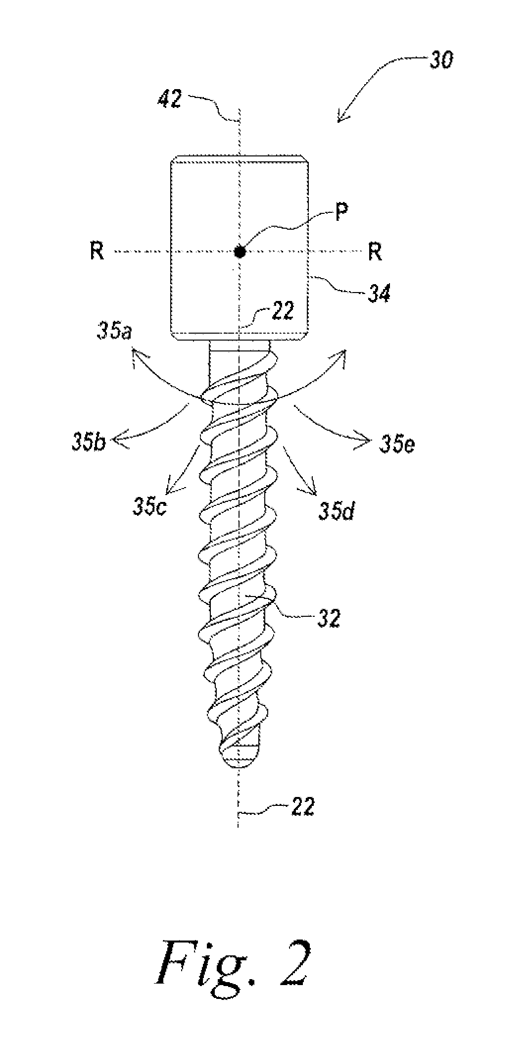
FIG. 1 is a diagram of the human body, and illustrates the three planes used to help describe anatomy. As shown in FIG. 1, the sagittal plane 20 splits the body from head to toe, from the back or posterior to the front or anterior. The coronal plane 24 splits the body from head to toe, side to side. The transverse plane 26 slices through the body yielding cross-sectional views. According to one aspect of the invention, a constrained motion bone screw assembly 30, shown in FIG. 2, includes an anchor portion 32 that is controllably pivotable in selected directions about one or more axes passing through a pivot point P with respect to a head portion 34, which may be a receiving portion, such as a rod-receiving portion, for receiving a spinal rod or other spinal fixation element.
The constrained motion bone screw assembly 30 of the present invention further selectively constrains the movement of the anchor portion 32 relative to the head portion 34 and/or a spinal fixation element received in the head portion 34 in one or more selected directions. As shown in FIG. 2, the anchor portion 32 relative to the head portion 34 in several directions about pivot point P, as indicated by arrows 35a-35e. The illustrative anchor portion 32 is prevented from pivoting about axis R-R, which extends through the pivot point P in a direction that is perpendicular to the longitudinal axis of 22 of the shaft. The anchor portion 32 is thus restricted from rotating about the head portion 34 in a direction that is perpendicular to the axis R-R. Preferably, the anchor portion 32 may be adjusted such that the longitudinal axis 22 of the bone anchor portion 32 extends at an angle of between 0.degree. and 90.degree. in the selected direction relative to the longitudinal axis 42 of the head portion 34.
In an alternate embodiment, a rod seat within the head portion 34 may be selectively movable to allow for relative movement between a spinal fixation element, such as a spinal rod, received in the head portion 34 and the bone anchor.
FIG. 3 is a top view illustrating the range of motion of the anchor portion 32 relative to the head portion 34 of a bone screw assembly 30 and a rod 12 received by the head portion 34 according to one embodiment of the invention. As shown in FIG. 3, the path of the anchor portion in the region surrounding the head portion may be limited in the sagittal plane, but movable in all other planes around the head portion, including the coronal plane. In FIG. 3, the anchor portion is pivotable not only about axis T-T, which is perpendicular to the longitudinal axis of the rod 12 received by the head portion 34, but also around several intermediate axes I1-I4 extending between the perpendicular axis T-T and the axis R-R to allow movement in the shaded region 40 surrounding the head portion 34. The anchor portion 32 is fixed from rotating about axis R-R, to prevent movement of the anchor portion in perpendicular region 44 extending perpendicular to the longitudinal axis 42 of the head portion.
As shown in FIG. 4, according to another embodiment of the invention, the anchor portion 32 may be fixed in all planes except for one selected plane, such as the coronal plane, to allow for movement of the anchor portion along a selected path in a single plane, such as the sagittal plane, while preventing movement of the anchor portion out of the single plane in all other directions relative to the head portion. In the embodiment of FIG. 4, the anchor portion is only pivotable about axis T-T, so that the range of motion of the anchor portion relative to the head portion is limited to the region 40' that is parallel to and aligned with the rod 12. Because the anchor cannot pivot about other axes, the anchor portion cannot move into the region 44' and is fixed in the plane defined by region 40'. The region 40' may encompass the sagittal plane when the screw assembly is inserted in a patient. One skilled in the art will recognize that ranges of motion between those illustrated in FIGS. 3 and 4 are also contemplated by the present invention.
FIG. 5 is an exploded view of an embodiment of a bone screw assembly 100 including a bone anchor portion 114, illustrated as a threaded shaft, coupled to a head portion, illustrated as a rod-receiving portion 140, to allow for controlled movement between the bone anchor 114 and rod-receiving portion 140 in accordance with the teachings of the invention. A compression and restriction member 180 for seating the head of the anchor portion 114 within the rod-receiving portion 140 includes restricting protrusions or other suitable mechanisms for selectively limiting the movement of the bone anchor relative to the rod-receiving portion to one or more selected directions. FIG. 6 is a side view of the assembled bone screw assembly 100. FIG. 7 is a cross-sectional view of the assembled bone screw assembly 100 along axis A-A shown in FIG. 6.
The bone anchor 114 comprises a joint portion, illustrated as a proximal anchor head 116, for coupling the bone anchor 114 to the rod-receiving portion 140, and an anchoring portion, illustrated as a distal shaft 118 configured to engage bone. The distal shaft 118 of the bone anchor 114 has a shaft diameter 120 and a longitudinal axis 122. The distal shaft 118 may include one or more bone engagement mechanisms to facilitate gripping engagement of the bone anchor to bone. In the illustrated embodiment, the distal shaft 118 includes an external thread 124 extending along at least a portion of the shaft for engaging bone. In the illustrated embodiment, the external thread 124 is a single lead thread that extends from a distal tip 126 of the shaft to the anchor head 116, though one skilled in the art will recognize that the external thread may extend along any selected portion of the shaft and have any suitable number of leads. Other suitable bone engagement mechanisms include, but are not limited to, one or more annular ridges, multiple threads, dual lead threads, variable pitched threads and/or any conventional bone engagement mechanism.
The rod-receiving member 140 receives the proximal head 116 of the bone anchor to couple the bone anchor 114 thereto, thereby coupling the bone to a rod or other element received in the rod-receiving member 140. The illustrative rod-receiving member 140 may be substantially similar to a head portion of a polyaxial screw assembly of the prior art. In a rest position, the longitudinal axis 122 of the bone anchor aligns with a longitudinal axis 142 extending through the rod-receiving member 140. The distal shaft 118 is pivotable relative to the rod-receiving member 140 about the proximal head 116 in one or more selected directions to angulate the longitudinal axis 122 relative to the longitudinal axis 142. The screw assembly 100 further includes one or more components, illustrated as the compression and restriction member 180, for preventing a pivoting movement of the distal shaft 118 in one or more directions, so that the distal shaft 118 cannot pivot in all 360 degrees around the rod-receiving member 140, thereby increasing the stability of the screw assembly in one or more planes, as described in detail below. For example, referring to FIGS. 6 and 7, the shaft is pivotable about axis T-T, but constrained from pivoting about axis R-R. Axis R-R is aligned with and parallel to the longitudinal axis r-r of the rod 12 in a selected plane and perpendicular to axis T-T, intersecting T-T at pivot point P, and may be substantially parallel to the longitudinal axis r-r of a rod to be received in the receiving portion 140.
The anchor head 116 of the bone anchor 114 may be configured to facilitate controlled adjustment of the bone anchor 114 relative to the receiving member 140 of the bone screw assembly. For example, the illustrative anchor head 116 may be substantially spherical and include curved side surfaces 161, 162 that are shaped to permit pivoting of the bone anchor 114 relative to the receiving member 140 in one or more selected directions. The curved side surfaces 161, 162 are preferably curved in three-dimensions to facilitate rotation of the anchor portion 114 relative to the receiving member 140. The illustrative anchor head 116 further includes two opposed flat side surfaces 163, 165 for constraining the pivoting movement to the one or more selected directions. The flat surfaces 163, 165 preferably extend substantially parallel to the longitudinal axis 122 of the shaft 118. While the illustrative embodiment shows two opposed flat side surfaces 163, 165, one skilled in the art will recognize that the head can have any suitable number of flat surfaces or other selected feature for limiting the path of the shaft 118 relative to the receiving portion 140 about any selected axis or axes. The top surface 167 of the anchor head 116 may be a generally planar surface to facilitate seating of the anchor within the rod-receiving portion 140 of the screw assembly. The anchor head 116 may also have surface texturing, knurling and/or ridges.
The illustrative bone screw assembly 100 further includes a compression and restriction member 180 for seating the anchor head 116 within the rod-receiving portion 140 of the screw 100 and for cooperating with the flat surfaces 163, 165 to constrain the movement of the anchor portion relative to the rod-receiving portion 140 and/or a rod received therein. The compression and restriction member 180 preferably forms a proximal rod seat 182 for seating a rod or other spinal fixation element and an opposed distal anchor seat 197 for engaging the anchor head 116. FIGS. 8A-8C illustrate an embodiment of the compression and restriction member 180 in detail, though one skilled in the art will recognize that the invention is not limited to the illustrative embodiment. The illustrative compression and restriction member 180 includes a cap 181 and restricting protrusions 192, 194 that extend from a lower surface 184 of the cap 181. The restricting protrusions 192, 194 form a track-like region 197 for receiving the anchor head 116 therebetween. The restricting protrusions 192, 194 are configured to mate with the flat surfaces 163, 165 of the anchor head 116 when the bone screw assembly 100 is assembled to guide and constrain the pivoting movement of the anchor head 116 relative to the receiving member 140. The illustrative restricting protrusions 192, 194 restrict movement of the anchor head 116 about axis T-T through a plane that is parallel to the flat faces 163, 165 of the proximal head 116 and the protrusions 192, 194.
In illustrative embodiment of FIGS. 5-8C, the plane through which the anchor portion 114 pivots is preferably defined by the longitudinal axis r-r of a rod inserted in the rod-receiving member 140 when the screw assembly 100 is assembled and the longitudinal axis 142 of the receiving member 140, similar to the assembly of FIG. 4B. However, one skilled in the art will recognize that the screw assembly 100 of FIGS. 5-8C may also be made to pivot in one or more other directions relative to the rod-receiving member 140.
In the embodiment shown in FIGS. 8A-8C, the restricting protrusions 192, 194 comprise separate inserts that couple to the cap 181. For example, the illustrative cap 181 includes side recesses 182a, 182b, each sized and configured to receive a top end of a restricting protrusion 192, 194, respectively. Each recess may further include a coupling projection 183a. 183b configured to mate with a hole or recess 195a, 195b6, in an associated restricting projection 192, 194, respectively, to facilitate coupling of the restricting projection to the cap. When coupled, each restricting projection extends past the bottom surface 184 of the cap 181 to cover and abut the flat surfaces 163, 165 of the anchor head 116 when the screw is assembled to control the movement of the anchor 114 relative to the rod-receiving member 140.
One skilled in the art will recognize that any suitable means for coupling the restricting protrusions to the cap 181 may be used. Alternatively, one or more of the restricting protrusions 192 or 194 may be integrally formed with the cap 181.
The restriction and compression member 180 is positioned within the receiving member 140 between the spinal rod 12 and the anchor head 116 when the bone screw assembly is assembled. The restriction and compression member 180 preferably engages the spinal rod 12 and the anchor head 116 to facilitate assembly of the constrained motion bone screw assembly 100.
According to another embodiment of the invention, a restriction member is provided for restricting pivoting of the bone anchor relative to the receiving member that does not necessarily serve as a compression member and/or a rod seat for seating the spinal rod or other spinal fixation element coupled to the bone anchor assembly.
FIGS. 9A-9C are detailed views of the illustrative rod-receiving member 140 when assembled. As shown in FIG. 9B, the flat surfaces 163, 165 of the proximal head interact with the flat surfaces of the protrusions 192, 195 to prevent movement or rotation of the shaft 118 against the flat surfaces. As shown in FIG. 9C, the curved side surfaces 161, 162 of the proximal head 116 allow for rotation of the bone anchor 114 relative to the rod-receiving member 140 in the direction indicated by arrow 90 about axis T-T.
In the illustrative embodiment, the restricting protrusions 192, 194 restrict the movement of the anchor shaft along a predetermined axis through an interference fit between the flat surfaces 163, 165 of the anchor head 116 and the restricting protrusions 192, 194. However, one skilled in the art will recognize that any suitable means may be used to restrict the movement of the shaft to one or more selected directions.
The invention is not limited to the illustrated mechanism for constraining the motion of the shaft relative to the rod-receiving portion. For example, as shown in FIG. 10, the anchor head 116 may include projections 166a, 166b extending from the side surfaces 163, 165, respectively that are configured to interface with recesses 196a, 196b in the restricting protrusions 192, 194 of the illustrative compression and restriction member to form a fixed pivot point about which the anchor 114 can rotate. Alternatively, the restricting protrusions may include projections configured to be received in the recesses formed in the side surfaces 163, 165 to facilitate coupling of a compression and restriction member to the proximal head that selectively limits rotation of the anchor in one or more directions while facilitating rotation in one or more other directions.
In addition, while the illustrative protrusions include flat surfaces configured to abut flat surfaces on the proximal head 116 to restrict rotation along a single axis, the restricting protrusions can alternatively be designed to allow for rotation about one or more of the intermediate axes I1-I4 shown in FIG. 3.
According to an illustrative embodiment of the invention, the receiving member 140 of the constrained motion bone screw assembly defines a recess 148. The recess 148 may be sized and shaped to receive a spinal rod 12 that extends along axis r-r or another suitable spinal fixation element. The exemplary spinal rod 12 may be seated within the recess 148 by aligning the spinal rod 12 and the recess 148 and advancing the spinal rod through a top bore hole into the recess 148. The configuration of the recess 148 may be varied to accommodate any suitable spinal fixation element. A suitable configuration for the receiving member 140 is described in the U.S. Patent Application Publication Numbers US 2004/0186473, US 2004/0181224 and US 2003/0100896, the contents of which are herein incorporated by reference.
In other embodiments, a spinal fixation element may be coupled to the bone anchor by alternative coupling mechanisms in place of a recess, including, for example, an offset coupling mechanism, such as a band clamp, sacral extender, or a lateral off-set connector.
The receiving member 140 may couple the spinal fixation element seated therein to the bone anchor 116 through any suitable means. For example, in the illustrative embodiment, the distal end of the receiving member includes an opening 160 through which at least a portion of the bone anchor 114 may extend. The distal opening is preferably smaller in size and shape than the anchor head 116 so as to engage the head 116 of the bone anchor 114. The distal opening 160 may define a seat 169 to allow the bone anchor 114 to selectively pivot relative to the receiving member. The screw is assembled by inserting the shaft through the first opening 160 until the head 116 is received in and constrained by the cavity 169.
The illustrative compression and restriction member cap 181 may be generally disc-shaped having a circular cross-section or other cross section preferably corresponding to a first bore 144 of the receiving member 140. A first surface of the compression and restriction member 180 may be configured to seat the spinal fixation element. In the illustrative embodiment, the seat 182 formed in the first surface has a generally arcuate cross-section having a curvature that may approximate the curvature of the exemplary spinal rod to be received therein. The second surface 184 may be configured to engage the anchor head 116. For example the second surface 184 may have a generally concave spherical shape or a tapered shape to engage the head of the bone anchor. The illustrative second surface 184 has a hemispherical shape to approximate the curvature of the anchor head 116. A bore 186 may extend through the cap 181 to allow for advancement of an instrument to the bone anchor 116 during assembly of the bone screw assembly.
After pivoting the bone anchor portion 116 about a selected axis in a selected direction relative to the receiving portion 140 by a selected degree, preferably between 0.degree. and 90.degree., a user can lock the orientation of the anchor portion relative to the rod-receiving portion by inserting a closure mechanism, such as a set screw. The closure mechanism secures a spinal rod 12 or other suitably configured spinal fixation element within the recess 148 of the receiving member 140 and locks the anchor head 116 in the selected orientation within and relative to the receiving member 140. In the illustrative embodiment, distal advancement of the closure mechanism into engagement with the spinal rod 12 in the recess 148 seats the spinal rod in the seat 182 of the compression and restriction member 180. The compression and restriction member 180 or other suitable restriction member may compress against the anchor head 116 to lock anchor in the selected orientation. Other suitable closure mechanisms may be employed to secure the spinal fixation element to the assembly and/or to lock the orientation of the bone anchor relative to the receiving portion.
While the illustrative restricting protrusions 192, 194 restrict pivoting of the anchor in a single direction about a single axis, one skilled in the art will recognize that the invention is not limited to restricting movement to a single direction about a single axis. As described above, the compression and restricting member 180 or other suitable restriction member may also be configured to allow some rotation of the anchor portion about the longitudinal axis 122, or allow pivoting in an intermediate direction about an intermediate axis I-I between axes T-T and R-R, while restricting the anchor from being able to move in any direction in the full 360 degree around the rod-receiving member 140, as shown in FIG. 3.
The receiving member 140, in certain exemplary embodiments, may be configured to receive a spinal fixation element, such as a rod, and couple the spinal fixation element to the bone screw assembly 100. As shown, the recess 148 is sized and shaped to receive a spinal rod, though one skilled in the art will recognize that the receiving member 140 may be configured to accommodate any suitable spinal fixation element.
In another embodiment of the invention, shown in FIG. 11, the proximal head 116' of the anchor portion 114' of a constrained motion bone screw assembly 100' is substantially spherical and curved on all side surfaces. The proximal head 116 includes a cavity 1162 formed in the top surface for receiving a ball end 1165 of a receiving member 140'. A retention ring 1164 inserted in the cavity 1162 secures the ball end 1165 within the cavity to couple the anchor portion 114' to the receiving member 140'. A support collar 1168 extends from the receiving member 140 over a portion of the proximal head 116' to maintain the position of the anchor portion and the receiving member. The ball end 1165 of the receiving member may include one or more flat surfaces that abut flat surfaces on the retention ring 1164 to constrict rotation of the anchor portion relative to the ball end in one or more selected directions.
Alternatively, the collar portion 1168 and the outer surface of the substantially spherical proximal head 116' may be configured so as to selectively prohibit rotation of the anchor portion relative to the receiving member in one or more selected directions while allowing rotation in one or more different directions.
Other details of the bottom-loading screw assembly shown in FIG. 11 are described in U.S. Pat. No. 6,623,485 which is incorporated herein by reference.
While the illustrative embodiment is a top-loading screw, one skilled in the art will recognize that the present invention encompasses a bottom-loading screw as well. For example, the first opening 160 of the receiving member may be larger than the head 116 to allow the head to pass through the opening 160 during assembly of the screw. The anchor head would then be inserted through a bottom opening of the receiving member and retained therein by a securing means, i.e., the anchor head is smaller in diameter than the bottom opening of the receiving member. In contrast, the anchor head of a top-loading screw is smaller than the bottom opening of the receiving member. A top-loading screw is assembled by inserting the shaft through the bottom opening, so that the anchor head is retained within a cavity in the receiving member. A bottom-loading screw is assembled by inserting the anchor head through the bottom opening, and inserting and activating the securing means to prevent the anchor head from passing through the opening.
FIG. 12 illustrates an embodiment of a bottom-loading constrained motion bone screw assembly 100'' according to an alternate embodiment of the invention. As shown, the receiving member 140'' is configured to receive a rod 12 and has a bottom opening 160'' sized and configured to allow insertion of the anchor head 116'' therethrough. A retaining member 190 is provided for retaining the anchor head 116'' within the receiving member 140''. The illustrative retaining member 190 is disposed around the bone anchor and in a groove of the receiver member 140'' to lock the anchor head 116'' within the cavity of the receiving member. As shown, a compression and restriction member 180'' comprises a capping member 181''. The capping member is shaped to accommodate the anchor head 116''. According to the illustrative embodiment, the capping member 181'' includes flat surfaces 192'', 194'', that are parallel to the longitudinal axis of the anchor shaft 118''. The anchor head 116'' includes flat surfaces 163'', 165'' configured to mate with the flat surfaces 192'', 194'' of the compression and restriction member 180'' to prevent rotation of the anchor about an axis that extends through the middle of the anchor head 116'' substantially parallel to the axis of the rod, i.e., the anchor cannot move in a direction transverse to the flat surfaces 163'' 165''. However, the spherical shape of the side surfaces of the anchor head adjacent to the flat surfaces allows for rotation of the anchor about the axis T-T. After angulation of the anchor about the ax is T-T by a selected amount, a closure mechanism may be inserted to lock the rod in the receiving member and/or lock the orientation of the anchor. Preferably, the closure mechanism presses down on the compression and restriction member 180'' and locks the bone anchor between the compression and restriction member 180'' and the retaining member 190.
Other details of the bottom-loading screw assembly 100'' shown in FIG. 12 are described in U.S. Pat. No. 6,280,442, which is incorporated herein by reference.
FIGS. 13A-C illustrate another embodiment of a constrained motion bone screw assembly 1000 according to an alternate embodiment of the invention. The constrained motion bone screw assembly 1000 of FIGS. 13A-13C allows for pivoting of a spinal rod received in the constrained motion bone screw assembly 1000 in at least one direction relative to the bone screw assembly 1000, while movement in other directions is restricted. The illustrative constrained motion bone screw assembly 1000 includes a bone anchor portion 1140, a rod-receiving portion 1400 and a movable rod seat 1800 housed by the rod-receiving portion 1400. The illustrative rod seat 1800 includes a lower rod seat 1800a and an upper rod seat 1800b. The lower rod seat 1800a and the upper rod seat 1800b cooperate to define the rod seat 1800 for receiving the rod therebetween. The rod seat 1800 is configured to move in one or more selected directions relative to the bone anchor portion 1140 and the rod-receiving portion 1400 to guide movement of the spinal rod 12 relative to the bone screw assembly 1000. In this manner, both the bone anchor portion 1140 and the rod-receiving portion can move relative to the spinal rod.
As shown, the bone anchor portion 1140 includes a shaft 1180 and a joint portion 1160. The joint portion 1160 includes a recess 1162 formed in a top surface thereof for receiving the lower rod seat 1800a. The recess 1162 preferably has a concave, spherical shape to allow pivoting of the lower rod seat 1800a within the recess 1162.
The illustrative lower rod seat 1800a, shown in detail in FIGS. 14A-14B, is substantially rectangular, with a spherical bottom surface 1802 configured to mate with a concave surface 1164 of the recess 1162. The lower rod seat 1800a includes a flat top surface 1804 for seating the rod 12. The lower rod seat 1800a may include retention recesses 1807a, 1807b on opposing side surfaces 1805, 1806, respectively, for receiving corresponding protrusions (not shown) on the rod-receiving portion 1400 to thereby couple the rod-receiving portion to the lower rod seat 1800a, while allowing selective relative movement between the rod seat and other components of the bone screw assembly 1000.
The rod receiving portion 1400 includes a body 1402, which may comprise one or more components coupled together, and the upper rod seat 1800b pivotably mounted to the body 1402. The upper rod seat 1800b includes a pivot point 1810 received in a recess 1403 of the body 1402 and a rod seat member 1812 connected to the pivot point 1810 via a connecting member 1814. The recess 1403 and pivot point 1810 cooperate to allow for pivoting of the upper rod seat 1800b in one or more selected directions only, while restricting pivoting in other directions.
As shown in FIG. 13C, the illustrative constrained motion bone screw assembly 1000 allows for pivoting of the rod seat 1800 relative to the bone anchor portion 1140 and/or the rod-receiving portion 1400. The selective pivoting of the rod seat 1800 in one or more selected directions to allow bending of the spinal rod 12 received therein relative to the bone anchor portion 1140 and the rod-receiving portion 1400. The lower rod seat and upper rod seat defining therebetween a movable channel for receiving the spinal rod 12 and for allowing for relative movement between the bone anchor portion 1140 and the spinal rod 12, as well as between the rod-receiving portion 1400 and the spinal rod 12. The upper rod seat 1800b pivots in a selected direction, and the lower rod seat 1800a rotates in the recess 1162 to guide the rod's movement, while retaining the rod therebetween. The coupling between the lower rod seat 1800a and the rod-receiving portion 1140 prevent movement in other directions. In this manner, the relative angle between the rod and both the bone anchor portion 1140 and the rod-receiving portion 1400 can be selectively varied in a first direction, while movement in other directions is prevented.
The components of the constrained motion bone anchor assembly of the illustrative embodiments of the invention may be manufactured from any suitable biocompatible material, including, but not limited to, metals and metal alloys such as titanium and stainless steel, polymers and/or ceramics. The components may be manufactured from the same or different materials though manufacturing processes known in the art.
The present invention has been described relative to an illustrative embodiment. Since certain changes may be made in the above constructions without departing from the scope of the invention, it is intended that all matter contained in the above description or shown in the accompanying drawings be interpreted as illustrative and not in a limiting sense.
It is also to be understood that the following claims are to cover all generic and specific features of the invention described herein, and all statements of the scope of the invention which, as a matter of language, might be said to fall therebetween.
* * * * *
D00000
D00001
D00002
D00003
D00004
D00005
D00006
D00007
D00008
D00009
D00010
D00011
XML
uspto.report is an independent third-party trademark research tool that is not affiliated, endorsed, or sponsored by the United States Patent and Trademark Office (USPTO) or any other governmental organization. The information provided by uspto.report is based on publicly available data at the time of writing and is intended for informational purposes only.
While we strive to provide accurate and up-to-date information, we do not guarantee the accuracy, completeness, reliability, or suitability of the information displayed on this site. The use of this site is at your own risk. Any reliance you place on such information is therefore strictly at your own risk.
All official trademark data, including owner information, should be verified by visiting the official USPTO website at www.uspto.gov. This site is not intended to replace professional legal advice and should not be used as a substitute for consulting with a legal professional who is knowledgeable about trademark law.