Contact element comprising a sensor
Troeger , et al. J
U.S. patent number 10,170,871 [Application Number 15/743,997] was granted by the patent office on 2019-01-01 for contact element comprising a sensor. This patent grant is currently assigned to HARTING ELECTRIC GMBH & CO. KG. The grantee listed for this patent is HARTING ELECTRIC GMBH & CO. KG. Invention is credited to Frank Brode, Lutz Troeger.

| United States Patent | 10,170,871 |
| Troeger , et al. | January 1, 2019 |
Contact element comprising a sensor
Abstract
An electrical contact element with an integrated sensor is provided. The contact element has a groove, at least a portion of which extends on a plug-in side of the contact element. An optical fiber is provided in the groove. The optical fiber is designed in such a way as to be suitable as a sensor for measuring the temperature or the air humidity.
| Inventors: | Troeger; Lutz (Osnabrueck, DE), Brode; Frank (Berlin, DE) | ||||||||||
|---|---|---|---|---|---|---|---|---|---|---|---|
| Applicant: |
|
||||||||||
| Assignee: | HARTING ELECTRIC GMBH & CO.
KG (DE) |
||||||||||
| Family ID: | 57042635 | ||||||||||
| Appl. No.: | 15/743,997 | ||||||||||
| Filed: | September 12, 2016 | ||||||||||
| PCT Filed: | September 12, 2016 | ||||||||||
| PCT No.: | PCT/DE2016/100425 | ||||||||||
| 371(c)(1),(2),(4) Date: | January 11, 2018 | ||||||||||
| PCT Pub. No.: | WO2017/045669 | ||||||||||
| PCT Pub. Date: | March 23, 2017 |
Foreign Application Priority Data
| Sep 17, 2015 [DE] | 10 2015 115 657 | |||
| Current U.S. Class: | 1/1 |
| Current CPC Class: | G01K 11/3206 (20130101); G01N 21/17 (20130101); G02B 6/3636 (20130101); H01R 13/6683 (20130101); G02B 6/02076 (20130101); H01R 13/04 (20130101); G01N 2201/088 (20130101) |
| Current International Class: | H01R 13/66 (20060101); G01K 11/32 (20060101); G01N 21/17 (20060101); G02B 6/36 (20060101); H01R 13/04 (20060101); G02B 6/02 (20060101) |
References Cited [Referenced By]
U.S. Patent Documents
| 4830457 | May 1989 | Asada |
| 4960318 | October 1990 | Nilsson |
| 5381498 | January 1995 | Bylander |
| 5634801 | June 1997 | Johnson |
| 6102572 | August 2000 | Hidano |
| 6886977 | May 2005 | Kaminski et al. |
| 2008/0013239 | January 2008 | Kopelman |
| 2012/0286580 | November 2012 | Sauerwein et al. |
| 2016/0333646 | November 2016 | Olin |
| 2017/0181646 | June 2017 | Hayes |
| 2017/0196479 | July 2017 | Liu |
| 2018/0113155 | April 2018 | Troger |
| 102338673 | Feb 2012 | CN | |||
| 202797505 | Mar 2013 | CN | |||
| 202799505 | Mar 2013 | CN | |||
| 3832185 | Mar 1990 | DE | |||
| 20201632 | Jun 2002 | DE | |||
| 69428907 | Jun 2002 | DE | |||
| 102004034475 | Feb 2005 | DE | |||
| 202007018305 | Jul 2008 | DE | |||
| 102011075593 | Nov 2012 | DE | |||
| 0274228 | Dec 1987 | EP | |||
| WO0213330 | Feb 2002 | WO | |||
Other References
|
German Office Action (w/machine translation) issued in application No. 10 2015 115 657.1, dated May 30, 2016 (6 pgs). cited by applicant . International Search Report (w/translation) and Written Opinion (w/o translation) issued in application No. PCT/DE2016/100425, dated Dec. 2, 2016 (15 pgs). cited by applicant . International Preliminary Report on Patentability (translation) issued in application No. PCT/DE2016/100425, dated Mar. 29, 2018 (9 pgs). cited by applicant. |
Primary Examiner: Harvey; James
Attorney, Agent or Firm: Hayes Soloway P.C.
Claims
The invention claimed is:
1. An electrical contact element comprising at least one groove with an optical fiber running in the groove wherein the optical fiber is designed as a sensor, and the groove starts at a connection side, remote from a plug-in side, of the contact element and runs to the plug-in side and ends again at the connection side.
2. The electrical contact element as claimed in claim 1, wherein the start and end of the groove run in parallel from the connection side to the plug-in side and are connected to each other on the plug-in side.
3. The electrical contact element as claimed in claim 1, wherein the groove forms a loop on the plug-in side.
4. The electrical contact element as claimed in claim 2, wherein the groove forms a loop on the plug-in side.
5. The electrical contact element as claimed in claim 1, wherein the optical fiber is pressed into the groove.
6. The electrical contact element as claimed in claim 1, wherein the optical fiber is bonded into the groove.
7. The electrical contact element as claimed claim 1, wherein the optical fiber has a Bragg grating.
8. The electrical contact element as claimed in claim 1, wherein the optical fiber is designed as a temperature sensor.
9. The electrical contact element as claimed in claim 1, wherein the optical fiber is designed as a humidity sensor.
Description
The invention relates to a contact element as claimed in the pre-characterizing clause of the independent claim 1.
Contact elements of this type are needed to produce an electrical contact between two lines. It is thus intended for the lines to be contacted to each other reversibly. Depending on the application and the current strength transferred, contact elements of this type can become very warm during operation. Because sometimes high transfer resistances occur at the contact points, the contact elements heat up.
PRIOR ART
In order to avoid failure of the contact elements because of excessively high temperatures, different contact elements with integrated sensors for monitoring the temperature are known from the prior art.
A measuring device on a plug-in contact is known from DE 20 2007 018 305 U1, with a plug-in region and a connection region which is arranged in a socket opening in a contact insert in a plug-in connector housing. The electrically conductive plug-in contact has, in the connection region, a recess in which a measurement sensor is embedded in an electrically non-conductive material.
A disadvantage of the contact elements known from the prior art is that, although the temperature is measured at the contact, it is not measured in the region of the contact point. The spatial separation of the measuring point and the contact point must be compensated by computer models. As a result, deviations between the actual temperature at the contact point of the contact element and the measured temperature can occur. Failure and malfunction of the contact element can thus not be excluded altogether.
OBJECT OF THE INVENTION
The object of the invention consists in providing a contact element with a sensor, wherein the measurement preferably takes place at the contact point of the contact element.
The object is achieved by the characterizing features of independent claim 1.
Advantageous embodiments of the invention are provided in the subclaims.
The invention is an electrical contact element as known from the prior art. According to the invention, the contact element has a groove in which an optical fiber runs. The groove is preferably provided on the plug-in side of the contact element. In a preferred embodiment, the groove runs directly through the contact point of the contact element.
The start and end of the groove are advantageously located on the connection side of the contact element. The optical fiber can thus pass on the connection side of the contact element into the groove and pass out of the latter. The groove thus forms a loop on the plug-in side of the contact element and in which the optical fiber is passed. In a further preferred embodiment, the groove advantageously passes in parallel from the connection side to the plug-in side.
An advantageous embodiment provides that the optical fiber is pressed into the groove and held therein. A further embodiment provides that the optical fiber is bonded into the groove.
According to the invention, the optical fiber has a so-called Bragg grating. The Bragg grating serves as an optical interference filter in the optical fiber. As a result, wavelengths lying within a filter bandwidth are reflected. The optical fiber designed in this way can consequently be used as a sensor for measuring the temperature.
The optical fiber can also be used to measure the humidity, by advantageous manipulation of the optical fiber (by the latter being split lengthwise).
As a result of the optical fiber being inserted according to the invention into the groove in the contact element, measurements can be made directly at the contact point of the contact element.
EXEMPLARY EMBODIMENT OF THE INVENTION
An exemplary embodiment of the invention is shown in the drawings and is explained in detail below. In the drawings:
FIG. 1 shows the plug-in side of a contact element;
FIG. 2 shows the plug-in side of a contact element in a further view;
FIG. 3 shows a cross-section through a contact element with an optical fiber;
FIG. 4 shows a cross-section through a contact element;
FIG. 5 shows a contact element with a view of the plug-in side; and
FIG. 6 shows a further contact element.
The drawings contain partially simplified schematic views. Identical reference numerals are used in part for the same, but possibly not identical, elements. Different views of the same elements can be at different scales.
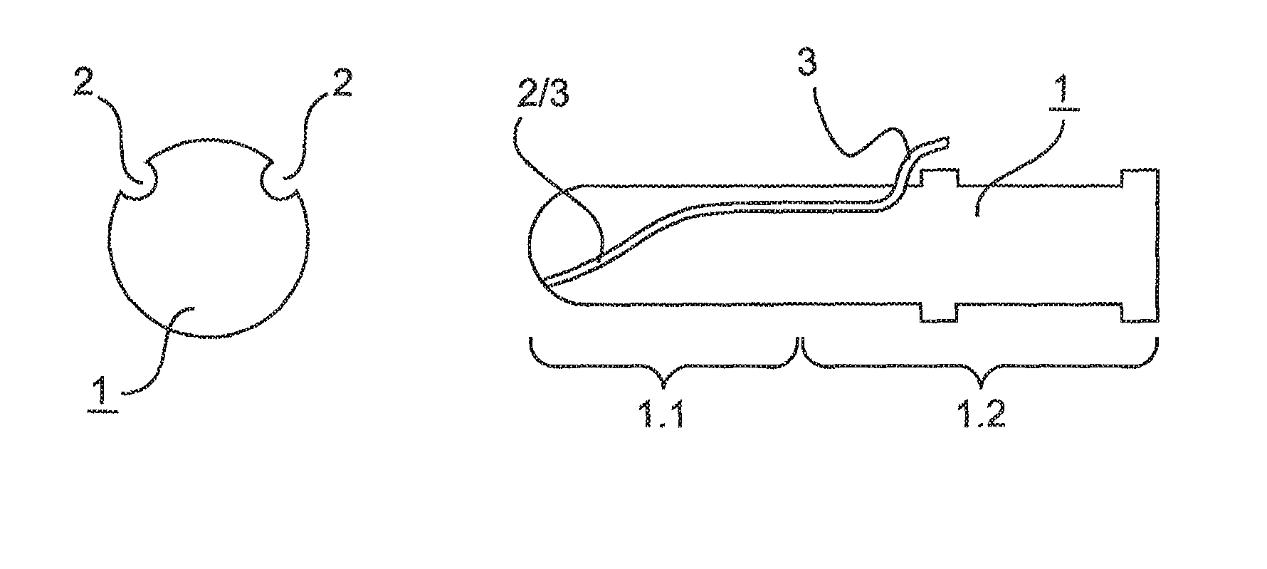
FIG. 1 shows a plug-in side 1.1 of a contact element 1 according to the invention. A groove 2 in the contact element 1 runs along the plug-in side 1.1. The groove 2 runs as far as the tip (shown on the left) of the plug-in side 1.1. At the tip, the groove 2 runs onto the rear side and from there back to where it started.
According to the invention, an optical fiber 3 is embedded in the groove 2. The optical fiber 3 is preferably pressed or bonded into the groove 2 and runs in the latter. The course is shown again in FIG. 2. The contact element 1 is shown from a different side. The course of the groove 2, how it runs in the right-hand region parallel to the left-hand tip of the contact element 1, can be seen here. At the tip of the contact element 1, the groove 2 runs once around the tip and continues on the rear side.
A cross-section of a contact element 1 is shown in FIGS. 3 and 4. The groove 2 receives the round optical fiber 3. Depending on the design of the groove 2, the optical fiber 3 is automatically clamped in the groove 2 or is fixed in the latter, for example using adhesive.
As a result of the rounded tip of the contact element 1, a curved course of the groove 2 and the optical fiber 3 is produced at the tip. The temperature of the whole plug-in side 1.1 of the contact element 1 can be measured particularly advantageously owing to the course of the groove 2 and the optical fiber 3 over the tip of the contact element 1.
A whole contact element 1 is additionally shown in in FIG. 6. The right-hand connection side 1.2 is provided for contacting an electrical line and designed as a crimped connection. In addition, the groove 2, into which the optical fiber 3 is inserted in the connection region 1.2, begins in the connection region 1.2.
The groove 2 and the optical fiber 3 run from the connection side 1.2 to the plug-in side 1.1. The groove 2 and optical fiber 3 form a loop at the tip of the plug-in side 1.1 and run on the rear side of the contact element 1 back to the connection side 1.2.
* * * * *
D00000
D00001
XML
uspto.report is an independent third-party trademark research tool that is not affiliated, endorsed, or sponsored by the United States Patent and Trademark Office (USPTO) or any other governmental organization. The information provided by uspto.report is based on publicly available data at the time of writing and is intended for informational purposes only.
While we strive to provide accurate and up-to-date information, we do not guarantee the accuracy, completeness, reliability, or suitability of the information displayed on this site. The use of this site is at your own risk. Any reliance you place on such information is therefore strictly at your own risk.
All official trademark data, including owner information, should be verified by visiting the official USPTO website at www.uspto.gov. This site is not intended to replace professional legal advice and should not be used as a substitute for consulting with a legal professional who is knowledgeable about trademark law.