Zoom lens and imaging apparatus
Tanaka , et al. J
U.S. patent number 10,168,513 [Application Number 15/854,315] was granted by the patent office on 2019-01-01 for zoom lens and imaging apparatus. This patent grant is currently assigned to FUJIFILM Corporation. The grantee listed for this patent is FUJIFILM Corporation. Invention is credited to Takuya Tanaka, Masaru Yonezawa.


View All Diagrams
| United States Patent | 10,168,513 |
| Tanaka , et al. | January 1, 2019 |
Zoom lens and imaging apparatus
Abstract
The zoom lens consists of, in order from an object side: a first lens group that has a positive refractive power; a second lens group that has a positive refractive power; a third lens group that has a negative refractive power; a fourth lens group that has a positive refractive power; and a fifth lens group that has a positive refractive power. The first lens group and the fifth lens group remain stationary with respect to an image plane during zooming. The second lens group, the third lens group, and the fourth lens group are moved by changing distances between the lens groups and adjacent groups in a direction of an optical axis during zooming, and are positioned to be closer to the image side at a telephoto end than at a wide-angle end. A stop is provided between the fourth lens group and the fifth lens group. In addition, Conditional Expression (1) is satisfied. 0.1<fw/f4<0.5 (1)
| Inventors: | Tanaka; Takuya (Saitama, JP), Yonezawa; Masaru (Saitama, JP) | ||||||||||
|---|---|---|---|---|---|---|---|---|---|---|---|
| Applicant: |
|
||||||||||
| Assignee: | FUJIFILM Corporation (Tokyo,
JP) |
||||||||||
| Family ID: | 62706462 | ||||||||||
| Appl. No.: | 15/854,315 | ||||||||||
| Filed: | December 26, 2017 |
Prior Publication Data
| Document Identifier | Publication Date | |
|---|---|---|
| US 20180188509 A1 | Jul 5, 2018 | |
Foreign Application Priority Data
| Jan 5, 2017 [JP] | 2017-000497 | |||
| Current U.S. Class: | 1/1 |
| Current CPC Class: | G02B 13/02 (20130101); G02B 15/24 (20130101); G02B 15/163 (20130101); G02B 15/14 (20130101) |
| Current International Class: | G02B 15/14 (20060101); G02B 15/163 (20060101); G02B 13/02 (20060101); G02B 15/24 (20060101) |
| Field of Search: | ;359/683 |
References Cited [Referenced By]
U.S. Patent Documents
| 2015/0241674 | August 2015 | Nagatoshi |
| 2016/0282592 | September 2016 | Abe |
| H07-294816 | Nov 1995 | JP | |||
| 2009-288619 | Dec 2009 | JP | |||
Attorney, Agent or Firm: Studebaker & Brackett PC
Claims
What is claimed is:
1. A zoom lens consisting of, in order from an object side: a first lens group that has a positive refractive power; a second lens group that has a positive refractive power; a third lens group that has a negative refractive power; a fourth lens group that has a positive refractive power; and a fifth lens group that has a positive refractive power, wherein the first lens group and the fifth lens group remain stationary with respect to an image plane during zooming, wherein the second lens group, the third lens group, and the fourth lens group are moved by changing distances between the lens groups and adjacent groups in a direction of an optical axis during zooming, and are positioned to be closer to the image side at a telephoto end than at a wide-angle end, wherein a stop is provided between the fourth lens group and the fifth lens group, and wherein Conditional Expression (1) is satisfied, 0.1<fw/f4<0.5 (1), where fw is a focal length of the whole system at the wide-angle end, and f4 is a focal length of the fourth lens group.
2. A zoom lens consisting of, in order from an object side: a first lens group that has a positive refractive power; a second lens group that has a positive refractive power; a third lens group that has a negative refractive power; a fourth lens group that has a positive refractive power; and a fifth lens group that has a positive refractive power, wherein the first lens group and the fifth lens group remain stationary with respect to an image plane during zooming, wherein the second lens group, the third lens group, and the fourth lens group are moved by changing distances between the lens groups and adjacent groups in a direction of an optical axis during zooming, and are positioned to be closer to the image side at a telephoto end than at a wide-angle end, wherein a stop is provided between the fourth lens group and the fifth lens group, and wherein Conditional Expression (2) is satisfied, 0.3<f1/f4<1.4 (2), where f1 is a focal length of the first lens group, and f4 is a focal length of the fourth lens group.
3. The zoom lens according to claim 1, wherein Conditional Expression (3) is satisfied, -5<f1/f3<-1 (3), where f1 is a focal length of the first lens group, and f3 is a focal length of the third lens group.
4. The zoom lens according to claim 1, wherein Conditional Expression (4) is satisfied, -2.3<fw/f3<-0.1 (4), where fw is a focal length of the whole system at the wide-angle end, and f3 is a focal length of the third lens group.
5. The zoom lens according to claim 1, wherein the first lens group consists of, in order from the object side, a first-a lens group that has a negative refractive power and remains stationary with respect to the image plane during focusing, a first-b lens group that has a positive refractive power and is moved by changing a distance in the direction of the optical axis between the first-b lens group and an adjacent lens group during focusing, and a first-c lens group that has a positive refractive power.
6. The zoom lens according to claim 5, wherein Conditional Expression (5) is satisfied, -3.4<f1c/f1a<-0.5 (5), where f1c is a focal length of the first-c lens group, and f1a is a focal length of the first-a lens group.
7. The zoom lens according to claim 5, wherein Conditional Expression (6) is satisfied, 3.1<f1b/f1<8 (6), where f1b is a focal length of the first-b lens group, and f1 is a focal length of the first lens group.
8. The zoom lens according to claim 5, wherein Conditional Expression (7) is satisfied, 2.4<f1b/f1c<8 (7), where f1b is a focal length of the first-b lens group, and f1c is a focal length of the first-c lens group.
9. The zoom lens according to claim 5, wherein Conditional Expression (8) is satisfied, 0.5<f1c/f1<1.4 (8), where f1c is a focal length of the first-c lens group, and f1 is a focal length of the first lens group.
10. The zoom lens according to claim 1, wherein Conditional Expression (1-1) is satisfied 0.15<fw/f4<0.4 (1-1).
11. The zoom lens according to claim 2, wherein Conditional Expression (2-1) is satisfied 0.5<f1/f4<1.3 (2-1).
12. The zoom lens according to claim 3, wherein Conditional Expression (3-1) is satisfied -4<f1/f3<-1.5 (3-1).
13. The zoom lens according to claim 4, wherein Conditional Expression (4-1) is satisfied -1.8<fw/f3<-0.2 (4-1).
14. The zoom lens according to claim 6, wherein Conditional Expression (5-1) is satisfied -2.9<f1c/f1a<-1.3 (5-1).
15. The zoom lens according to claim 7, wherein Conditional Expression (6-1) is satisfied 3.7<f1b/f1<6 (6-1).
16. The zoom lens according to claim 8, wherein Conditional Expression (7-1) is satisfied 3<f1b/f1c<6 (7-1).
17. The zoom lens according to claim 9, wherein Conditional Expression (8-1) is satisfied 0.8<f1c/f1<1.3 (8-1).
18. The zoom lens according to claim 2, wherein Conditional Expression (3) is satisfied, -5<f1/f3<-1 (3), where f1 is a focal length of the first lens group, and f3 is a focal length of the third lens group.
19. An imaging apparatus comprising the zoom lens according to claim 1.
20. An imaging apparatus comprising the zoom lens according to claim 2.
Description
CROSS REFERENCE TO RELATED APPLICATIONS
The present application claims priority under 35 U.S.C. .sctn. 119 to Japanese Patent Application No. 2017-000497 filed on Jan. 5, 2017. The above application is hereby expressly incorporated by reference, in its entirety, into the present application.
BACKGROUND OF THE INVENTION
1. Field of the Invention
The present invention relates to a zoom lens suitable for electronic cameras such as movie imaging cameras, broadcast cameras, digital cameras, video cameras, and surveillance cameras, and to an imaging apparatus comprising the zoom lens.
2. Description of the Related Art
As zoom lenses used in electronic cameras such as movie imaging cameras, broadcast cameras, digital cameras, video cameras, and surveillance cameras, zoom lenses disclosed in JP1995-294816A (JP-H07-294816A) and JP2009-288619A have been proposed.
SUMMARY OF THE INVENTION
In imaging apparatuses such as movie imaging cameras and broadcast cameras, there is a demand for a zoom lens that is compact and lightweight but has favorable optical performance. In particular, reduction in size and reduction in weight are strongly demanded for imaging modes focusing on maneuverability and operability. Meanwhile, there is also a demand for cameras in the above-mentioned field to be capable of performing imaging with a wide angle of view. However, it is not easy to achieve both wide angle and reduction in size.
It can not be said that All the lens systems described in JP1995-294816A (JP-H07-294816A) and JP2009-288619A satisfy both wide angle and miniaturization sufficiently with respect to the level that has been demanded in recent years.
The present invention has been made in consideration of the above-mentioned situations, it is an object of the present invention to provide a zoom lens for which reduction in size and weight is achieved and high optical performance is achieved with wide angle, and an imaging apparatus comprising the zoom lens.
A first zoom lens of the present invention consists of, in order from an object side: a first lens group that has a positive refractive power; a second lens group that has a positive refractive power: a third lens group that has a negative refractive power; a fourth lens group that has a positive refractive power; and a fifth lens group that has a positive refractive power. The first lens group and the fifth lens group remain stationary with respect to an image plane during zooming. The second lens group, the third lens group, and the fourth lens group are moved by changing distances between the lens groups and adjacent groups in a direction of an optical axis during zooming, and are positioned to be closer to the image side at a telephoto end than at a wide-angle end. A stop is provided between the fourth lens group and the fifth lens group. In addition, Conditional Expression (1) is satisfied. 0.1<fw/f4<0.5 (1)
fw is a focal length of the whole system at the wide-angle end.
f4 is a focal length of the fourth lens group.
It is more preferable that Conditional Expression (1-1) is satisfied. 0.15<fw/f4<0.4 (1-1)
A second zoom lens of the present invention consists of, in order from an object side: a first lens group that has a positive refractive power; a second lens group that has a positive refractive power; a third lens group that has a negative refractive power; a fourth lens group that has a positive refractive power; and a fifth lens group that has a positive refractive power. The first lens group and the fifth lens group remain stationary with respect to an image plane during zooming. The second lens group, the third lens group, and the fourth lens group are moved by changing distances between the lens groups and adjacent groups in a direction of an optical axis during zooming, and are positioned to be closer to the image side at a telephoto end than at a wide-angle end. In addition, it is preferable that a stop is provided between the fourth lens group and the fifth lens group. In addition, Conditional Expression (2) is satisfied. 0.3<f1/f4<1.4 (2)
Here, f1 is a focal length of the first lens group,
f4 is a focal length of the fourth lens group.
It is more preferable that Conditional Expression (2-1) is satisfied. 0.5<f1/f4<1.3 (2-1)
It is preferable that the first and second zoom lenses of the present invention satisfy Conditional Expression (3). It is more preferable that Conditional Expression (3-1) is satisfied. -5<f1/f3<-1 (3) -4<f1/f3<-1.5 (3-1)
Here, f1 is a focal length of the first lens group,
f3 is a focal length of the third lens group.
It is preferable that Conditional Expression (4) is satisfied. It is more preferable that Conditional Expression (4-1) is satisfied. -2.3<fw/f3<-0.1 (4) -1.8<fw/f3<-0.2 (4-1)
Here, fw is a focal length of the whole system at the wide-angle end, and
f3 is a focal length of the third lens group.
It is preferable that the first lens group consists of, in order from the object side, a first-a lens group that has a negative refractive power and remains stationary with respect to the image plane during focusing, a first-b lens group that has a positive refractive power and is moved by changing a distance in the direction of the optical axis between the first-b lens group and an adjacent lens group during focusing, and a first-c lens group that has a positive refractive power.
In this case, it is preferable that Conditional Expression (5) is satisfied. It is more preferable that Conditional Expression (5-1) is satisfied. -3.4<f1c/f1a<-0.5 (5) -2.9<f1c/f1a<-1.3 (5-1)
Here, f1c is a focal length of the first-c lens group, and
f1a is a focal length of the first-a lens group.
It is preferable that Conditional Expression (6) is satisfied. It is more preferable that Conditional Expression (6-1) is satisfied. 3.1<f1b/f1<8 (6) 3.7<f1b/f1<6 (6-1)
Here, f1b is a focal length of the first-b lens group, and
f1 is a focal length of the first lens group.
It is preferable that Conditional Expression (7) is satisfied. It is more preferable that Conditional Expression (7-1) is satisfied. 2.4<f1b/f1c<8 (7) 3<f1b/f1c<6 (7-1)
Here, f1b is a focal length of the first-b lens group, and
f1c is a focal length of the first-c lens group.
It is preferable that Conditional Expression (8) is satisfied. It is more preferable that Conditional Expression (8-1) is satisfied. 0.5<f1c/f1<1.4 (8) 0.8<f1c/f1<1.3 (8-1)
Here, f1c is a focal length of the first-c lens group, and
f1 is a focal length of the first lens group.
An imaging apparatus of the present invention comprises the above-mentioned zoom lens of the present invention.
It should be noted that the term "consists of .about." means that the zoom lens may include not only the above-mentioned elements but also lenses substantially having no powers, optical elements, which are not lenses, such as a stop, a mask, a cover glass, and a filter, and mechanism parts such as a lens flange, a lens barrel, an imaging element, and a hand shaking correction mechanism.
Further, reference signs of surface shapes and refractive powers of the lenses are assumed as those in paraxial regions in a case where some lenses have aspheric surfaces.
Further, in a case where the zoom lens of the present invention has a focusing function, all the signs of the focal lengths in the conditional expressions are signs in a case where the object at infinity in focus.
Each of the first and second zoom lenses of the present invention consists of, in order from an object side: a first lens group that has a positive refractive power: a second lens group that has a positive refractive power; a third lens group that has a negative refractive power; a fourth lens group that has a positive refractive power; and a fifth lens group that has a positive refractive power. The first lens group and the fifth lens group remain stationary with respect to an image plane during zooming. The second lens group, the third lens group, and the fourth lens group are moved by changing distances between the lens groups and adjacent groups in a direction of an optical axis during zooming, and are positioned to be closer to the image side at a telephoto end than at a wide-angle end. A stop is provided between the fourth lens group and the fifth lens group. In addition, the zoom lenses satisfy Conditional Expressions (1) and (2). Therefore, it is possible to provide a zoom lens for which reduction in size and weight is achieved and high optical performance is achieved with wide angle, and an imaging apparatus comprising the zoom lens. 0.1<fw/f4<0.5 (1) 0.3<f1/f4<1.4 (2)
BRIEF DESCRIPTION OF THE DRAWINGS
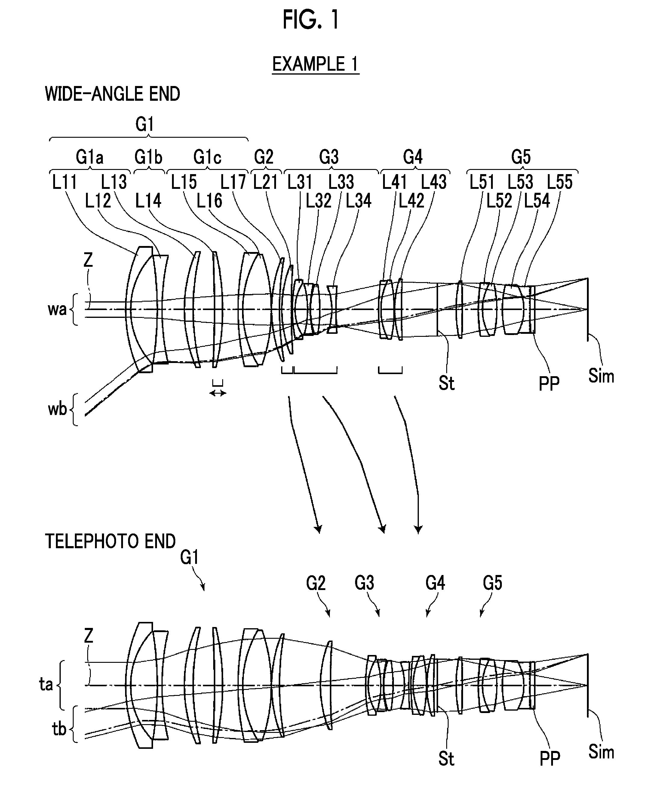
FIG. 1 is a cross-sectional view illustrating a lens configuration of a zoom lens (common to Example 1) according to first and second embodiments of the present invention.
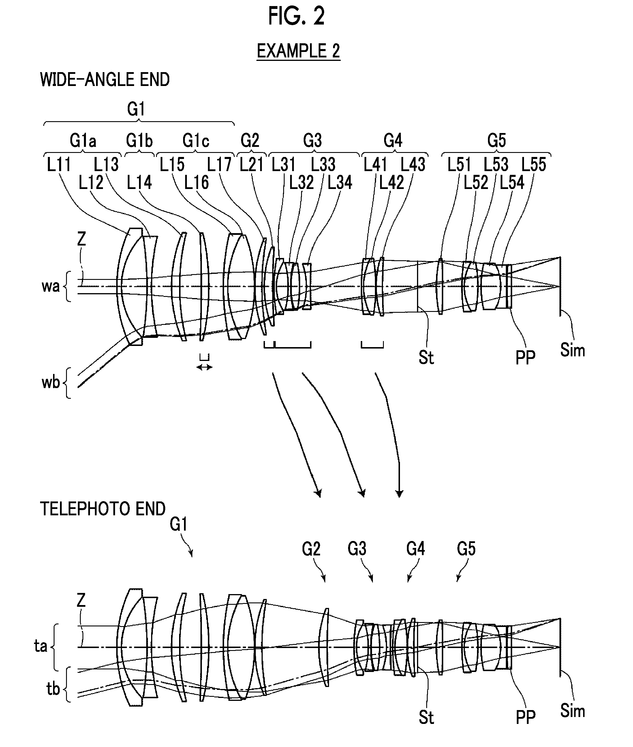
FIG. 2 is a cross-sectional view illustrating a lens configuration of a zoom lens of Example 2 of the present invention.
FIG. 3 is a cross-sectional view illustrating a lens configuration of a zoom lens of Example 3 of the present invention.
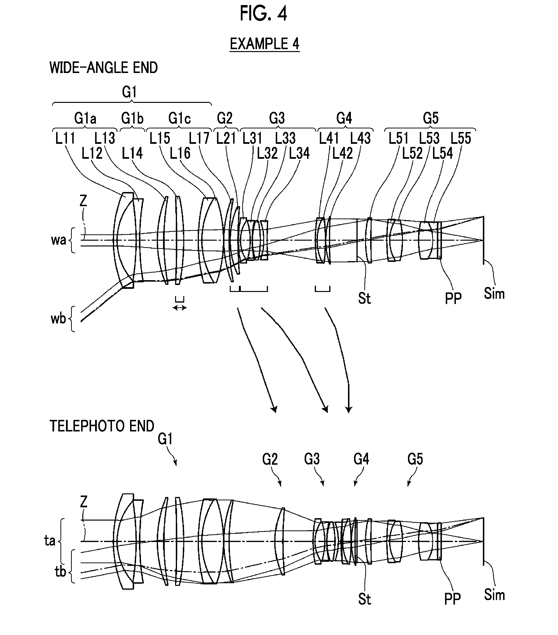
FIG. 4 is a cross-sectional view illustrating a lens configuration of a zoom lens of Example 4 of the present invention.
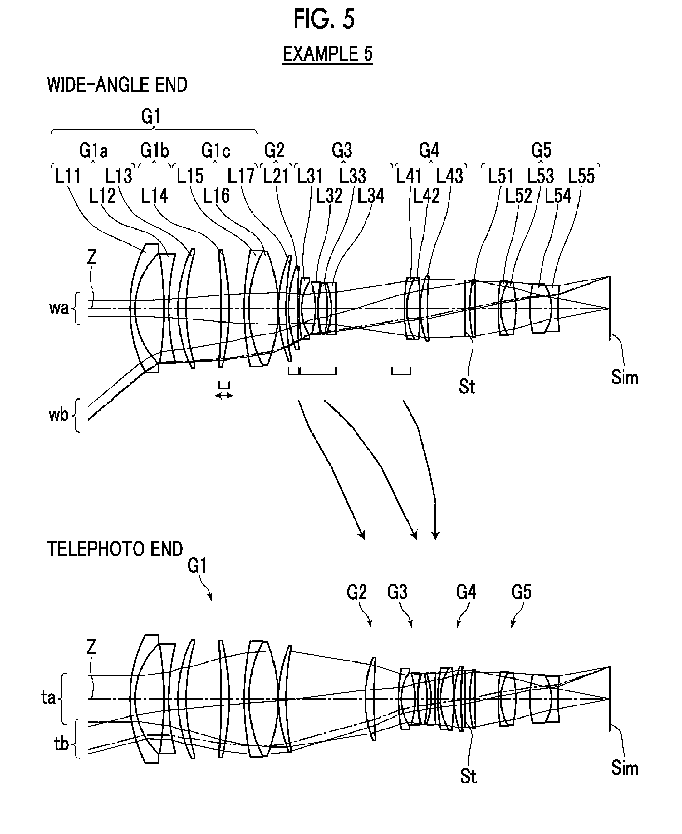
FIG. 5 is a cross-sectional view illustrating a lens configuration of a zoom lens of Example 5 of the present invention.
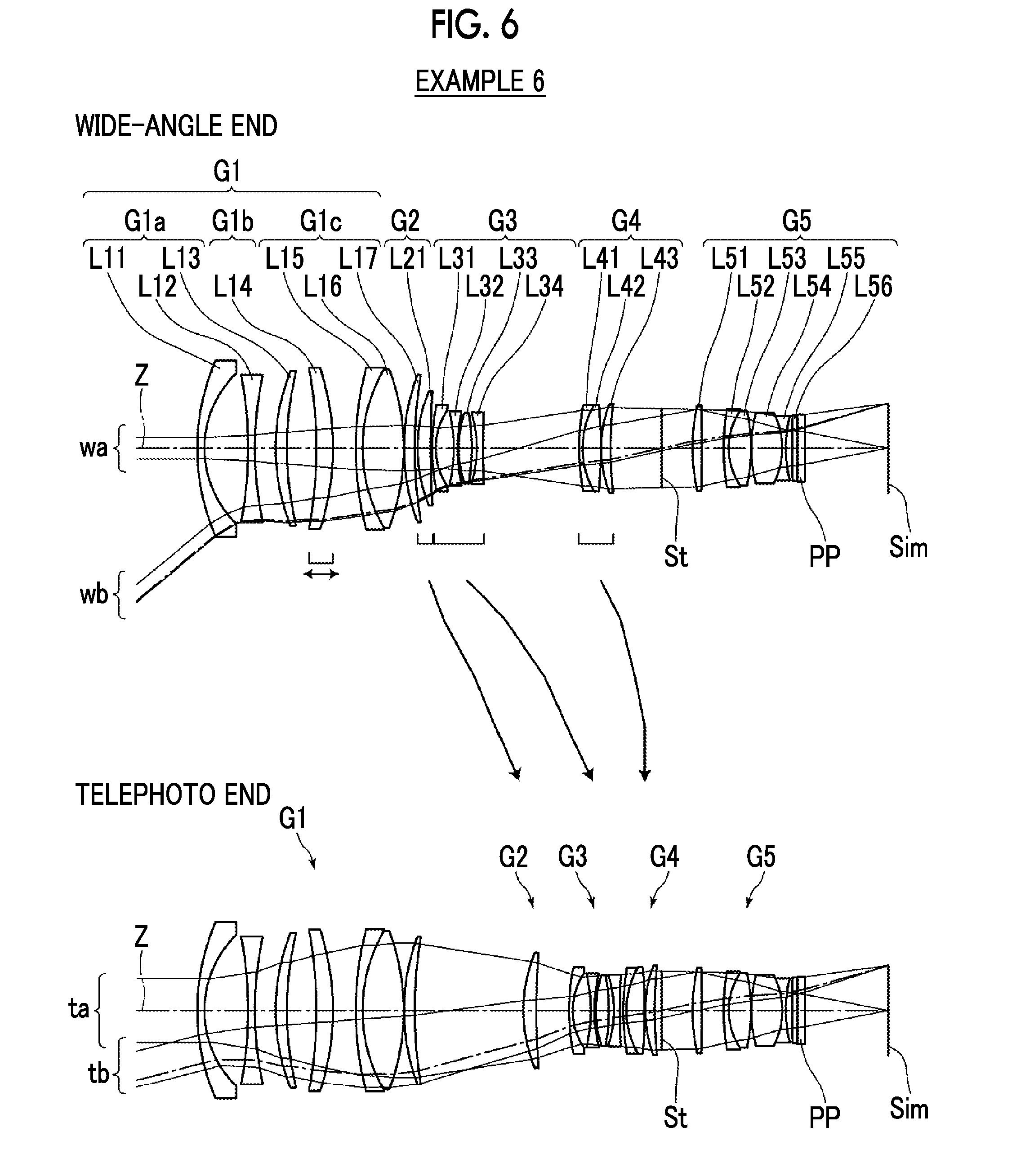
FIG. 6 is a cross-sectional view illustrating a lens configuration of a zoom lens of Example 6 of the present invention.
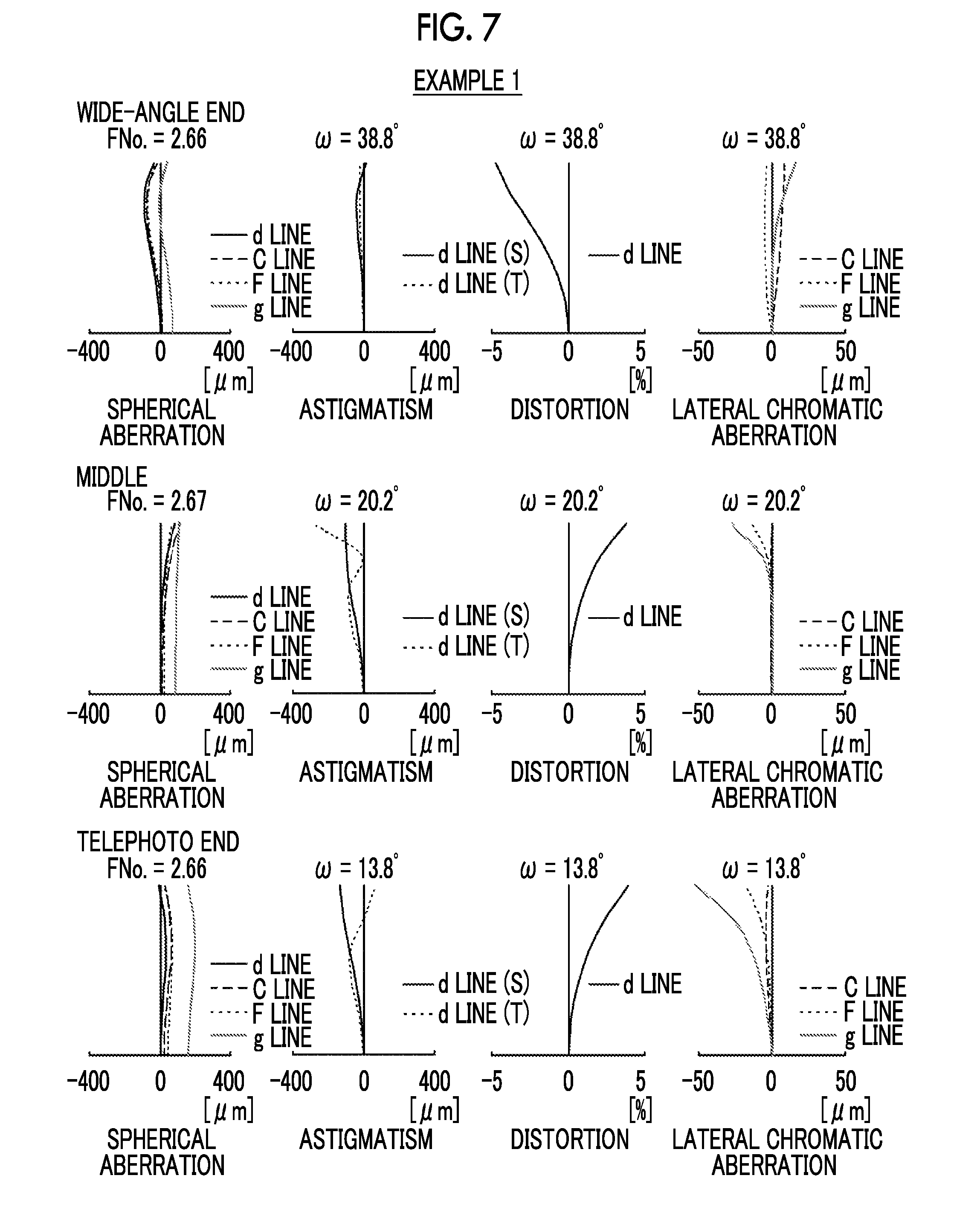
FIG. 7 is a diagram of aberrations of the zoom lens of Example 1 of the present invention.
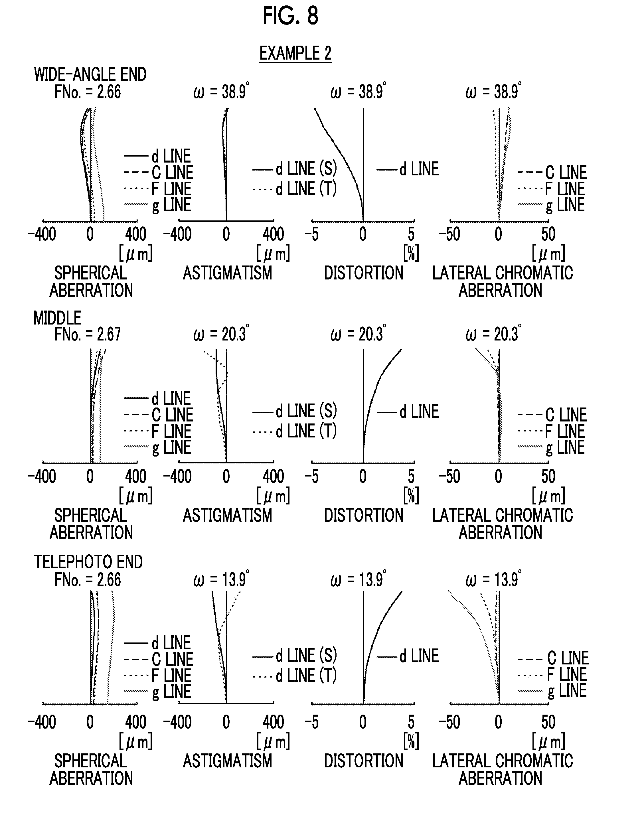
FIG. 8 is a diagram of aberrations of the zoom lens of Example 2 of the present invention.
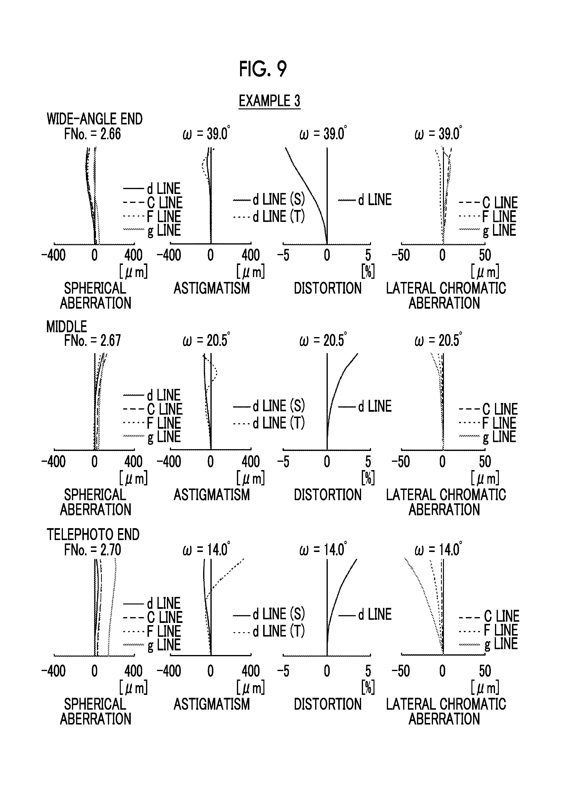
FIG. 9 is a diagram of aberrations of the zoom lens of Example 3 of the present invention.
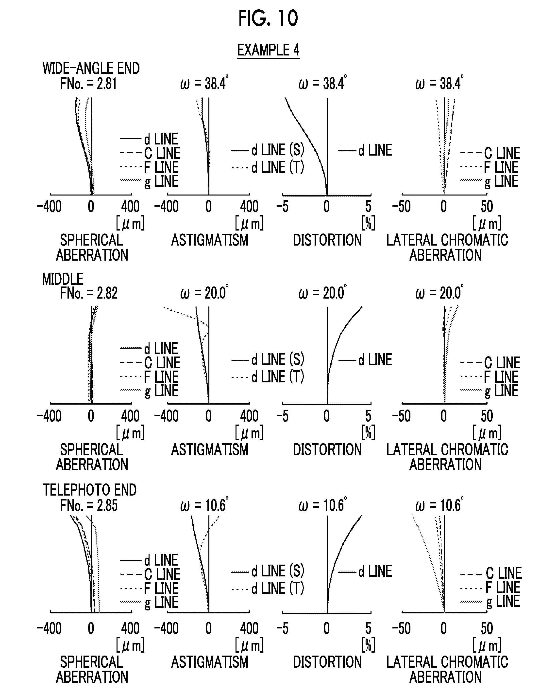
FIG. 10 is a diagram of aberrations of the zoom lens of Example 4 of the present invention.
FIG. 11 is a diagram of aberrations of the zoom lens of Example 5 of the present invention.
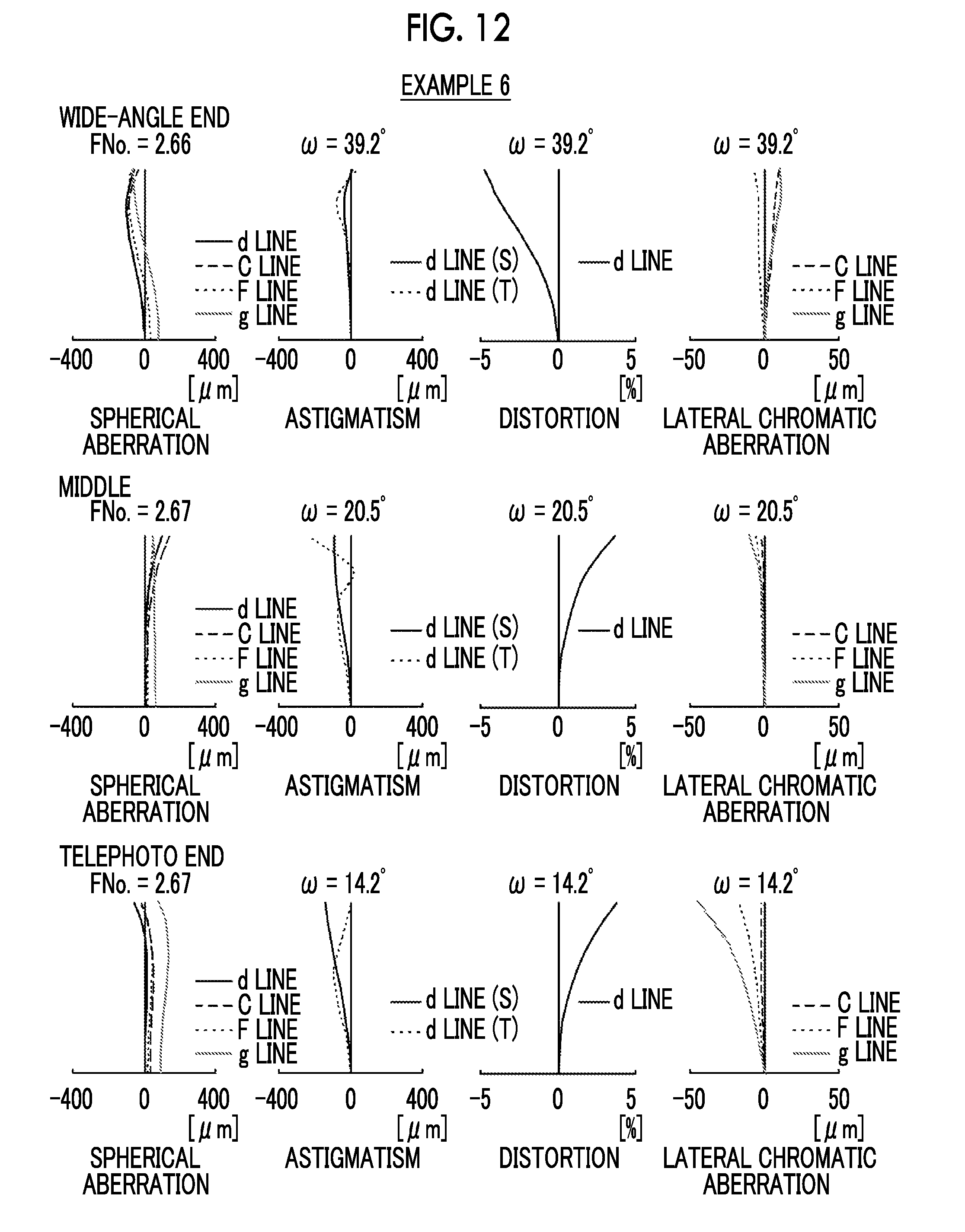
FIG. 12 is a diagram of aberrations of the zoom lens of Example 6 of the present invention.
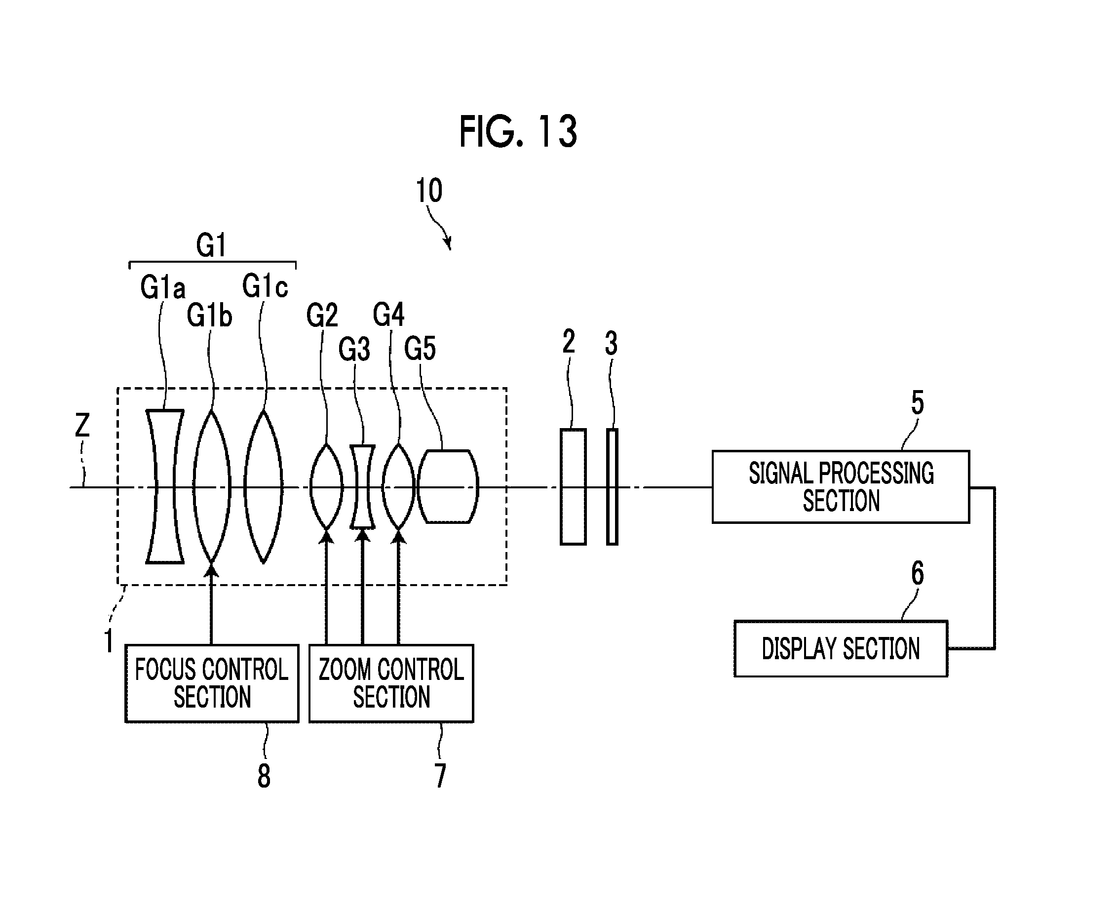
FIG. 13 is a schematic configuration diagram of an imaging apparatus according to an embodiment of the present invention.
DESCRIPTION OF THE PREFERRED EMBODIMENTS
Hereinafter, embodiments of the present invention will be described with reference to drawings. FIG. 1 is a cross-sectional view illustrating a lens configuration and an optical path of a zoom lens according to a first embodiment of the present invention. In FIG. 1, aberrations in the wide-angle end state are shown in the upper part, on-axis rays wa and rays with the maximum angle of view wb are shown as rays. In addition, aberrations in the telephoto end state are shown in the lower part, and on-axis rays ta and rays with the maximum angle of view tb are shown as rays. It should be noted that the example shown in FIG. 1 corresponds to the zoom lens of Example 1 to be described later. FIG. 1 shows a state where the object at infinity is in focus, where the left side of the drawing is the object side and the right side of the drawing is the image side. It should be noted that the aperture stop St shown in the drawing does not necessarily indicate its size and shape, and indicates a position of the stop on the optical axis Z.
In order to mount the zoom lens on an imaging apparatus, it is preferable to provide various filters and/or a protective cover glass based on specification of the imaging apparatus. Thus, FIG. 1 shows an example where a plane-parallel-plate-like optical member PP, in which those are considered, is disposed between the lens system and the image plane Sim. However, a position of the optical member PP is not limited to that shown in FIG. 1, and it is also possible to adopt a configuration in which the optical member PP is omitted.
A zoom lens of the present invention is consists of, in order from an object side: a first lens group G1 that has a positive refractive power; a second lens group G2 that has a positive refractive power: a third lens group G3 that has a negative refractive power; a fourth lens group G4 that has a positive refractive power; and a fifth lens group G5 that has a positive refractive power. The first lens group G1 and the fifth lens group G5 remain stationary with respect to an image plane Sim during zooming. The second lens group G2, the third lens group G3, and the fourth lens group G4 are moved by changing distances between the lens group Gs and adjacent groups in a direction of an optical axis during zooming, and are positioned to be closer to the image side at a telephoto end than at a wide-angle end. An aperture stop St is provided between the fourth lens group G4 and the fifth lens group G5.
By forming the first lens group G1 closest to the object side as a group having a positive refractive power, it is possible to shorten the total length of the lens system. As a result, there is an advantage in reduction in size. Further, the second lens group G2 has a positive refractive power, and is formed as a movable group that moves from the object side to the image side during zooming from the wide-angle end to the telephoto end. Thereby, it is possible to suppress the effective diameter of the second lens group G2 on the telephoto side, and it is possible to suppress the outer diameter of the second lens group G2. As a result, it is possible to achieve reduction in size and weight. Further, it is possible to optimally correct lateral chromatic aberration and distortion at the wide-angle end, and it is possible to suppress fluctuation in lateral chromatic aberration and distortion caused by zooming. Thus, it is possible to achieve wide angle. Furthermore, the third lens group G3 has a main zooming function, but the second lens group G2 having a positive refractive power is disposed between the third lens group G3 and the first lens group G1 which remains stationary during zooming, and the second lens group G2 is moved during zooming. Thereby, it is possible to suppress change in spherical aberration during zooming. In addition, by forming the fourth lens group G4 as a movable group, it is possible to correct defocusing during zooming. Further, by making the fourth lens group G4 have a positive refractive power, it is possible to minimize the height of the axial marginal ray through the fifth lens group G5. Thus, it is possible to suppress occurrence of spherical aberration in the fifth lens group G5. Further, by forming the fifth lens group G5 closest to the image side as a group having a positive refractive power, it is possible to suppress an increase in incident angle of the principal ray of the off-axis rays incident onto the image plane Sim. Thus, it is possible to suppress shading.
The zoom lens is configured to satisfy Conditional Expression (1). By not allowing the result of Conditional Expression (1) to be equal to or less than the lower limit, the amount of movement of the fourth lens group G4 during zooming is suppressed. As a result, it is possible to prevent the total lens length from increasing, and it becomes easy to reduce fluctuation in spherical aberration in a zooming range from the wide-angle end to the middle. By not allowing the result of Conditional Expression (1) to be equal to or greater than the upper limit, it is possible to prevent the angle of the principal ray, which is emitted from the fourth lens group G4, to the optical axis Z from becoming excessively large. Thus, there is an advantage in achieving wide angle. In addition, in a case where Conditional Expression (1-1) is satisfied, it is possible to obtain more favorable characteristics. 0.1<fw/f4<0.5 (1) 0.15<fw/f4<0.4 (1-1)
Here, fw is a focal length of the whole system at the wide-angle end, and
f4 is a focal length of the fourth lens group G4.
Subsequently, a second embodiment of the present invention will be described with reference to the drawing. FIG. 1 is a cross-sectional view illustrating a lens configuration and an optical path of a zoom lens according to a second embodiment of the present invention. The described contents of FIG. 1 are the same as those of the first embodiment.
The zoom lens of the second embodiment differs from the zoom lens of the first embodiment only in that the zoom lens satisfies Conditional Expression (2) instead of Conditional Expression (1). Here, the description of a part, which is the same as that of the zoom lens of the first embodiment, will be omitted.
The zoom lens is configured to satisfy Conditional Expression (2). By not allowing the result of Conditional Expression (2) to be equal to or less than the lower limit, it is possible to minimize the amount of movement of the fourth lens group G4 for the image point correction. Therefore, it is possible to prevent the total lens length from increasing. This leads to reduction in outer diameter of the lens for minimizing the effective diameter of the fifth lens group G5. By not allowing the result of Conditional Expression (2) to be equal to or greater than the upper limit, the positive refractive power of the fourth lens group G4 can be prevented from becoming excessively large among the positive refractive powers on the object side of the aperture stop St. Therefore, it is possible to prevent the power of the first lens group G1 from becoming relatively small, and there is an advantage in achieving wide angle. In addition, in a case where Conditional Expression (2-1) is satisfied, it is possible to obtain more favorable characteristics. 0.3<f1/f4<1.4 (2) 0.5<f1/f4<1.3 (2-1)
Here, f1 is a focal length of the first lens group G1, and
f4 is a focal length of the fourth lens group G4.
It is preferable that the zoom lens of the first and second embodiments satisfies Conditional Expression (3). By not allowing the result of Conditional Expression (3) to be equal to or less than the lower limit, the refractive power of the third lens group G3 can be prevented from becoming relatively excessively strong, and thus it becomes easy to suppress fluctuations in various aberrations during zooming. By not allowing the result of Conditional Expression (3) to be equal to or greater than the upper limit, the refractive power of the third lens group G3 can be prevented from becoming relatively excessively weak. Thus, it is possible to obtain a zoom ratio sufficient for the third lens group G3, and it is possible to reduce the load on the second lens group G2. It should be noted that Conditional Expression (3-1), more preferably, Conditional Expression (3-2) is satisfied. Then, it is possible to obtain more favorable characteristics. -5<f1/f3<-1 (3) -4<f1/f3<-1.5 (3-1) -4<f1/f3<-2 (3-2)
Here, f1 is a focal length of the first lens group G1, and
f3 is a focal length of the third lens group G3.
It is preferable that Conditional Expression (4) is satisfied. By not allowing the result of Conditional Expression (4) to be equal to or less than the lower limit, it becomes easy to suppress fluctuations in various off-axis aberrations caused by zooming on the wide-angle side, particularly, to suppress distortion and field curvature aberration, and to suppress fluctuations in various aberrations caused by zooming on the telephoto side, particularly, to suppress spherical aberration. By not allowing the result of Conditional Expression (4) to be equal to or greater than the upper limit, the amount of movement of the third lens group G3 necessary for zooming is suppressed. As a result, it is possible to achieve reduction in size of the whole lens. It should be noted that Conditional Expression (4-1), more preferably, Conditional Expression (4-2) is satisfied. Then, it is possible to obtain more favorable characteristics. -2.3<fw/f3<-0.1 (4) -1.8<fw/f3<-0.2 (4-1) -1.3<fw/f3<-0.3 (4-2)
Here, fw is a focal length of the whole system at the wide-angle end, and
f3 is a focal length of the third lens group G3.
It is preferable that the first lens group G1 consists of, in order from the object side, a first-a lens group G1a that has a negative refractive power and remains stationary with respect to the image plane during focusing, a first-b lens group G1b that has a positive refractive power and is moved by changing a distance in the direction of the optical axis between the first-b lens group G1b and an adjacent lens group during focusing, and a first-c lens group G1c that has a positive refractive power. With such a configuration, it is possible to reduce fluctuation in spherical aberration, longitudinal chromatic aberration, and an angle of view during focusing.
In this case, it is preferable that Conditional Expression (5) is satisfied. By not allowing the result of Conditional Expression (5) to be equal to or less than the lower limit, there is an advantage in correcting off-axis aberrations such as field curvature and distortion at the wide-angle end. By not allowing the result of Conditional Expression (5) to be equal to or greater than the upper limit, there is an advantage in correcting spherical aberration and field curvature at the telephoto end. It should be noted that Conditional Expression (5-1), more preferably, Conditional Expression (5-2) is satisfied. Then, it is possible to obtain more favorable characteristics. -3.4<f1c/f1a<-0.5 (5) -2.9<f1c/f1a<-1.3 (5-1) -2.4<f1c/f1a<-1.3 (5-2)
Here, f1c is a focal length of the first-c lens group G1c, and
f1 a is a focal length of the first-a lens group G1a.
It is preferable that Conditional Expression (6) is satisfied. By not allowing the result of Conditional Expression (6) to be equal to or less than the lower limit, there is an advantage in correcting fluctuation in aberration during focusing. By not allowing the result of Conditional Expression (6) to be equal to or greater than the upper limit, the amount of movement of the first-b lens group G1b during focusing is suppressed. As a result, there is an advantage in reducing the total length of the first lens group G1 as a focusing group. In addition, in a case where Conditional Expression (6-1) is satisfied, it is possible to obtain more favorable characteristics. 3.1<f1b/f1<8 (6) 3.7<f1b/f1<6 (6-1)
Here, f1b is a focal length of the first-b lens group G1b, and
f1 is a focal length of the first lens group G1.
It is preferable that Conditional Expression (7) is satisfied. By not allowing the result of Conditional Expression (7) to be equal to or less than the lower limit, there is an advantage in correcting fluctuation in aberration during focusing. By not allowing the result of Conditional Expression (7) to be equal to or greater than the upper limit, the amount of movement of the first-b lens group G1b during focusing is suppressed. As a result, there is an advantage in reducing the total length of the first lens group G1 as a focusing group. In addition, in a case where Conditional Expression (7-1) is satisfied, it is possible to obtain more favorable characteristics. 2.4<f1b/f1c<8 (7) 3<f1b/f1c<6 (7-1)
Here, f1b is a focal length of the first-b lens group G1b, and
f1c is a focal length of the first-c lens group G1c.
It is preferable that Conditional Expression (8) is satisfied. By not allowing the result of Conditional Expression (8) to be equal to or less than the lower limit, the amount of movement of the first-b lens group G1b during focusing is suppressed. As a result, there is an advantage in reducing the total length of the first lens group G1 as a focusing group. By not allowing the result of Conditional Expression (8) to be equal to or greater than the upper limit, there is an advantage in correcting spherical aberration and field curvature. In addition, there is an advantage in correcting spherical aberration and field curvature during focusing. In addition, in a case where Conditional Expression (8-1) is satisfied, it is possible to obtain more favorable characteristics. 0.5<f1c/f1<1.4 (8) 0.8<f1c/f1<1.3 (8-1)
Here, f1c is a focal length of the first-c lens group G1c, and
f1 is a focal length of the first lens group G1.
In the example shown in FIG. 1, the optical member PP is disposed between the lens system and the image plane Sim. However, various filters such as a lowpass filter and a filter for cutting off a specific wavelength region may not be disposed between the lens system and the image plane Sim. Instead, such various filters may be disposed between the lenses, or coating for functions the same as those of various filters may be performed on a lens surface of any lens.
Next, numerical examples of the zoom lens of the present invention will be described.
First, a zoom lens of Example 1 will be described. FIG. 1 is a cross-sectional view illustrating a lens configuration of the zoom lens of Example 1. In FIG. 1 and FIGS. 2 to 6 corresponding to Examples 2 to 6 to be described later, aberrations in the wide-angle end state are shown in the upper part, on-axis rays wa and rays with the maximum angle of view wb are shown as rays. In addition, aberrations in the telephoto end state are shown in the lower part, and on-axis rays ta and rays with the maximum angle of view tb are shown as rays. Each drawing shows a state where the object at infinity is in focus, where the left side of the drawing is the object side and the right side of the drawing is the image side. It should be noted that the aperture stop St shown in the drawing does not necessarily indicate its size and shape, and indicates a position of the stop on the optical axis Z.
The zoom lens of Example 1 is composed of, in order from the object side: a first lens group G1 that has a positive refractive power; a second lens group G2 that has a positive refractive power; a third lens group G3 that has a negative refractive power; a fourth lens group G4 that has a positive refractive power; and a fifth lens group G5 that has a positive refractive power.
The first lens group G1 is composed of seven lenses L11 to L17. The second lens group G2 is composed of only one lens L21. The third lens group G3 is composed of four lenses L31 to L34. The fourth lens group G4 is composed of three lenses L41 to L43. The fifth lens group G5 is composed of five lenses L51 to L55.
The first lens group G1 is composed of a first-a lens group G1a consisting of three lenses L11 to L13, a first-b lens group G1b consisting of only one lens L14, and a first-c lens group G1c consisting of three lenses L15 to L17.
Table 1 shows basic lens data of the zoom lens of Example 1, Table 2 shows data about specification, and Table 3 shows data about variable surface distances. Hereinafter, meanings of the reference signs in the tables are, for example, as described in Example 1, and are basically the same as those in Examples 2 to 6.
In the lens data of Table 1, the column of the surface number shows surface numbers. The surface of the elements closest to the object side is the first surface, and the surface numbers sequentially increase toward the image plane side. The column of the radius of curvature shows radii of curvature of the respective surfaces. The column of the surface distance shows distances on the optical axis Z between the respective surfaces and the subsequent surfaces. Further, the column of nd shows a refractive index of each optical element at the d line (a wavelength of 587.6 nm (nanometers)), and the column of .nu.d shows an Abbe number of each optical element at the d line (a wavelength of 587.6 nm).
Here, the sign of the radius of curvature is positive in a case where a surface has a shape convex toward the object side, and is negative in a case where a surface has a shape convex toward the image plane side. In the basic lens data, the aperture stop St and the optical member PP are additionally noted. In a place of a surface number of a surface corresponding to the aperture stop St, the surface number and a term of (stop) are noted. Further, in the lens data of Table 1, in each place of the surface distance which is variable during zooming, DD[surface number] is noted. Numerical values each corresponding to the DD[surface number] are shown in Table 3.
In the data about the specification of Table 2, values of the zoom ratio, the focal length f', the F number FNo., and the total angle of view 2.omega. are noted.
In the basic lens data, the data about specification, and the data about variable surface distances, a degree is used as a unit of an angle, and mm is used as a unit of a length, but appropriate different units may be used since the optical system can be used even in a case where the system is enlarged or reduced in proportion.
TABLE-US-00001 TABLE 1 Example 1.cndot.Lens Data Surface Radius of Surface Number Curvature Distance nd .nu.d 1 70.24179 2.300 2.00100 29.13 2 36.36367 12.396 3 -159.96478 2.199 1.90043 37.37 4 107.72364 10.430 5 68.75317 4.094 1.72084 27.06 6 110.51072 9.897 7 -510.10131 3.814 1.59135 68.82 8 -116.83894 7.167 9 116.55003 2.200 1.77690 26.16 10 49.94545 13.319 1.52189 77.37 11 -77.88064 0.120 12 62.90982 3.661 1.87893 41.16 13 136.05012 DD[13] 14 55.52215 4.442 1.59282 68.62 15 305.49002 DD[15] 16 73.27567 1.199 1.90000 35.22 17 22.56967 5.871 18 -41.89884 1.200 1.59282 68.62 19 48.62680 0.120 20 34.85092 4.364 1.90000 22.99 21 -72.06425 5.347 22 -31.23903 2.000 1.89982 36.86 23 167.99167 DD[23] 24 102.81542 1.051 1.90000 35.43 25 30.34761 6.224 1.48789 86.36 26 -63.72015 0.151 27 45.14367 3.160 1.89999 38.00 28 260.36165 DD[28] 29(Stop) .infin. 8.811 30 65.53926 2.832 1.90000 38.00 31 -523.43116 7.492 32 81.27867 1.900 1.78519 31.90 33 23.99563 6.685 1.49700 81.54 34 -56.11055 2.597 35 48.30450 10.010 1.49700 81.54 36 -22.30546 3.000 1.98943 29.91 37 125.66404 0.000 38 .infin. 2.300 1.51633 64.14 39 .infin. 24.682
TABLE-US-00002 TABLE 2 Example 1.cndot.Specification (d LINE) WIDE-ANGLE END Middle TELEPHOTO END ZOOM RATIO 1.0 2.0 3.0 f' 18.954 37.908 56.861 FNo. 2.66 2.67 2.66 2.omega.[.degree.] 77.6 40.4 27.6
TABLE-US-00003 TABLE 3 Example 1.cndot.Zoom Distance WIDE-ANGLE END Middle TELEPHOTO END DD[13] 1.071 9.558 19.049 DD[15] 0.499 14.032 16.372 DD[23] 19.810 10.027 0.973 DD[28] 16.671 4.434 1.657
FIG. 7 shows aberration diagrams of the zoom lens of Example 1. In addition, spherical aberration, astigmatism, distortion, and lateral chromatic aberration at the wide-angle end are shown in order from the upper left side of FIG. 7, spherical aberration, astigmatism, distortion, and lateral chromatic aberration at the middle position are shown in order from the middle left side of FIG. 7, and spherical aberration, astigmatism, distortion, and lateral chromatic aberration at the telephoto end are shown in order from the lower left side of FIG. 7. Such aberration diagrams show aberrations in a state where the object distance is set as an infinite distance. The diagram of aberrations illustrating spherical aberration, astigmatism, and distortion indicates aberrations that occur in a case where the d line (a wavelength of 587.6 nm) is set as a reference wavelength. In the spherical aberration diagram, aberrations at the d line (a wavelength of 587.6 nm), the C line (a wavelength of 656.3 nm), the F line (a wavelength of 486.1 nm), and the g line (a wavelength of 435.8 nm) are respectively indicated by the solid line, the long dashed line, the short dashed line, and the gray solid line. In the astigmatism diagram, aberrations in sagittal and tangential directions are respectively indicated by the solid line and the short dashed line. In the lateral chromatic aberration diagram, aberrations at the C line (a wavelength of 656.3 nm), the F line (a wavelength of 486.1 nm), and the g line (a wavelength of 435.8 nm) are respectively indicated by the long dashed line, the short dashed line, and the gray solid line. In addition, in the spherical aberration diagram, FNo. means an F number. In the other aberration diagrams, .omega. means a half angle of view.
Next, a zoom lens of Example 2 will be described. FIG. 2 is a cross-sectional view illustrating a lens configuration of the zoom lens of Example 2. Compared with the zoom lens of Example 1, the zoom lens of Example 2 is the same in terms of a configuration of the refractive power of each group and a configuration of the number of lenses of each group. Further, Table 4 shows basic lens data of the zoom lens of Example 2, Table 5 shows data about specification, and Table 6 shows data about variable surface distances. FIG. 8 shows aberration diagrams thereof.
TABLE-US-00004 TABLE 4 Example 2.cndot.Lens Data Surface Radius of Surface Number Curvature Distance nd .nu.d 1 68.23470 2.300 2.00100 29.13 2 35.78947 12.731 3 -159.03830 2.199 1.90043 37.37 4 106.64171 9.965 5 68.89785 4.026 1.72018 27.10 6 108.88536 10.803 7 -521.31279 3.703 1.58864 69.19 8 -120.73054 7.236 9 116.44845 2.200 1.80127 27.16 10 52.39928 13.319 1.52233 77.29 11 -73.28829 0.120 12 63.70101 3.537 1.88243 40.82 13 132.10539 DD[13] 14 54.00777 4.196 1.57131 71.52 15 287.09824 DD[15] 16 73.83460 1.199 1.90000 33.01 17 22.63769 5.890 18 -43.20111 1.200 1.59282 68.62 19 51.32314 0.120 20 37.26063 4.317 1.90000 23.07 21 -63.84021 3.384 22 -33.92273 2.000 1.89879 37.68 23 264.90729 DD[23] 24 103.60879 1.050 1.90000 35.82 25 30.20395 6.093 1.47565 88.42 26 -85.42533 0.150 27 44.88548 3.177 1.90000 38.00 28 212.80129 DD[28] 29(Stop) .infin. 9.291 30 64.18568 3.074 1.89999 38.00 31 -338.70465 9.583 32 82.91454 1.215 1.74935 29.32 33 23.17418 6.762 1.49700 81.54 34 -61.71318 1.566 35 50.42563 10.010 1.49700 81.54 36 -22.03001 3.000 1.98635 30.12 37 103.79307 0.000 38 .infin. 2.300 1.51633 64.14 39 .infin. 24.283
TABLE-US-00005 TABLE 5 Example 2.cndot.Specification (d LINE) WIDE-ANGLE END Middle TELEPHOTO END ZOOM RATIO 1.0 2.0 3.0 f' 18.852 37.704 56.556 FNo. 2.66 2.67 2.66 2.omega.[.degree.] 77.8 40.6 27.8
TABLE-US-00006 TABLE 6 Example 2 Zoom Distance WIDE-ANGLE END Middle TELEPHOTO END DD[13] 1.153 14.908 28.049 DD[15] 0.623 12.255 13.310 DD[23] 25.164 12.477 1.153 DD[28] 17.483 4.783 1.911
Next, a zoom lens of Example 3 will be described. FIG. 3 is a cross-sectional view illustrating a lens configuration of the zoom lens of Example 3. Compared with the zoom lens of Example 1, the zoom lens of Example 3 is the same in terms of a configuration of the refractive power of each group and a configuration of the number of lenses of each group. Further, Table 7 shows basic lens data of the zoom lens of Example 3, Table 8 shows data about specification, and Table 9 shows data about variable surface distances. FIG. 9 shows aberration diagrams thereof.
TABLE-US-00007 TABLE 7 Example 3.cndot.Lens Data Surface Radius of Surface Number Curvature Distance nd .nu.d 1 62.69514 2.299 2.00100 29.13 2 33.73916 13.590 3 -141.10134 2.200 1.89992 37.47 4 110.49207 4.490 5 62.57255 3.835 1.75211 25.05 6 91.17471 14.892 7 -322.87061 3.659 1.59282 68.62 8 -107.64311 7.588 9 122.22826 2.199 1.77699 28.92 10 57.09231 13.320 1.51194 79.04 11 -66.87108 0.120 12 61.62506 3.588 1.88300 40.76 13 121.20140 DD[13] 14 52.54675 3.912 1.59051 68.94 15 384.98538 DD[15] 16 90.86711 1.199 1.90000 31.91 17 22.15340 6.471 18 -42.84531 1.199 1.59282 68.62 19 60.83884 0.120 20 41.21202 4.012 1.90000 26.50 21 -64.98293 0.617 22 -34.90200 2.000 1.72776 51.66 23 -830.66341 DD[23] 24 88.95522 1.051 1.90000 38.00 25 28.17694 6.050 1.43875 94.66 26 -183.82577 0.150 27 43.19999 3.088 1.90000 32.61 28 158.51445 DD[28] 29(Stop) .infin. 2.000 30 53.80944 2.757 1.90000 38.00 31 397.21405 10.352 32 78.35478 1.100 1.79467 28.91 33 23.10345 7.029 1.49700 81.54 34 -50.73233 7.219 35 47.19526 10.010 1.49700 81.54 36 -20.79019 3.000 1.99799 29.34 37 104.36447 0.000 38 .infin. 2.300 1.51633 64.14 39 .infin. 22.012
TABLE-US-00008 TABLE 8 Example 3.cndot.Specification (d LINE) WIDE-ANGLE END Middle TELEPHOTO END ZOOM RATIO 1.0 2.0 3.0 f' 18.773 37.547 56.320 FNo. 2.66 2.67 2.70 2.omega.[.degree.] 78.0 41.0 28.0
TABLE-US-00009 TABLE 9 Example 3.cndot.Zoom Distance WIDE-ANGLE END Middle TELEPHOTO END DD[13] 1.188 25.744 45.928 DD[15] 0.771 7.331 5.655 DD[23] 36.574 17.097 1.345 DD[28] 16.192 4.553 1.797
Next, a zoom lens of Example 4 will be described. FIG. 4 is a cross-sectional view illustrating a lens configuration of the zoom lens of Example 4. Compared with the zoom lens of Example 1, the zoom lens of Example 4 is the same in terms of a configuration of the refractive power of each group and a configuration of the number of lenses of each group. Further, Table 10 shows basic lens data of the zoom lens of Example 4, Table 11 shows data about specification, and Table 12 shows data about variable surface distances. FIG. 10 shows aberration diagrams thereof.
TABLE-US-00010 TABLE 10 Example 4.cndot.Lens Data Surface Radius of Surface Number Curvature Distance nd .nu.d 1 75.43452 2.300 2.00100 29.13 2 36.61520 11.626 3 -158.53008 2.199 1.89919 37.61 4 148.94755 10.875 5 70.61573 3.941 1.73914 25.88 6 139.97863 7.859 7 -555.35725 4.379 1.58171 70.12 8 -134.48299 8.899 9 104.16586 2.199 1.82385 29.00 10 48.18130 13.319 1.51971 77.73 11 -78.29202 0.120 12 69.10274 3.290 1.87983 41.07 13 126.18802 DD[13] 14 50.22693 4.744 1.59263 68.65 15 224.32942 DD[15] 16 69.37232 1.201 1.89999 32.83 17 21.32743 6.021 18 -40.54826 1.200 1.59283 68.62 19 52.95905 0.119 20 36.32561 4.894 1.87368 22.97 21 -55.63430 2.132 22 -34.18995 2.001 1.90000 37.29 23 201.15049 DD[23] 24 99.24431 1.051 1.90001 37.82 25 30.06991 5.171 1.44157 94.18 26 -100.59908 0.151 27 44.55772 2.242 1.90000 36.27 28 216.58347 DD[28] 29(Stop) .infin. 5.223 30 57.13395 3.336 1.83221 44.11 31 353.92249 9.740 32 95.97311 1.729 1.70462 34.50 33 23.86217 7.810 1.49700 81.54 34 -53.94742 9.961 35 51.91054 8.793 1.49700 81.54 36 -21.62364 3.001 1.96232 31.74 37 258.48265 0.000 38 .infin. 2.300 1.51633 64.14 39 .infin. 25.968
TABLE-US-00011 TABLE 11 Example 4.cndot.Specification (d LINE) WIDE-ANGLE END Middle TELEPHOTO END ZOOM RATIO 1.0 2.0 3.9 f' 19.174 38.347 74.777 FNo. 2.81 2.82 2.85 2.omega.[.degree.] 76.8 40.0 21.2
TABLE-US-00012 TABLE 12 Example 4.cndot.Zoom Distance WIDE-ANGLE TELEPHOTO END Middle END DD[13] 0.669 10.205 28.005 DD[15] 0.284 14.652 18.464 DD[23] 29.414 18.268 -0.422 DD[28] 16.893 4.135 1.213
Next, a zoom lens of Example 5 will be described. FIG. 5 is a cross-sectional view illustrating a lens configuration of the zoom lens of Example 5. Compared with the zoom lens of Example 1, the zoom lens of Example 5 is the same in terms of a configuration of the refractive power of each group and a configuration of the number of lenses of each group. Further, Table 13 shows basic lens data of the zoom lens of Example 5, Table 14 shows data about specification, and Table 15 shows data about variable surface distances. FIG. 11 shows aberration diagrams thereof.
TABLE-US-00013 TABLE 13 Example 5.cndot.Lens Data Surface Radius of Surface Number Curvature Distance nd .nu.d 1 64.01482 2.300 2.00100 29.13 2 34.25815 13.114 3 -152.86228 2.199 1.90043 37.37 4 102.27104 4.189 5 61.27633 3.754 1.75089 25.13 6 86.86483 15.742 7 -392.22913 3.708 1.59282 68.62 8 -111.87408 6.820 9 118.61091 2.200 1.76223 27.92 10 56.30436 13.319 1.51111 79.17 11 -68.33072 0.121 12 61.84838 3.476 1.88300 40.76 13 118.22863 DD[13] 14 52.84953 4.029 1.59282 68.62 15 293.38233 DD[15] 16 81.06942 1.201 1.90000 31.88 17 22.16046 6.204 18 -41.63340 1.200 1.59282 68.62 19 58.23181 0.121 20 40.04869 4.256 1.90000 25.03 21 -57.89196 1.701 22 -34.29561 2.000 1.79228 42.51 23 447.37689 DD[23] 24 80.85851 1.051 1.90000 38.00 25 28.27674 6.063 1.43875 94.66 26 -139.22704 0.151 27 42.31198 3.176 1.90000 34.85 28 159.87600 DD[28] 29(Stop) .infin. 2.000 30 58.12158 2.560 1.89999 38.00 31 431.24761 10.496 32 73.64056 1.101 1.77901 28.87 33 23.30934 6.919 1.49700 81.54 34 -52.50435 6.349 35 44.65602 10.010 1.49700 81.54 36 -20.75262 3.000 1.99162 29.77 37 106.07495 23.521
TABLE-US-00014 TABLE 15 Example 5.cndot.Zoom Distance WIDE-ANGLE END Middle TELEPHOTO END DD[13] 1.125 19.836 35.771 DD[15] 0.668 10.718 11.116 DD[23] 31.038 15.085 1.249 DD[28] 17.177 4.368 1.872
TABLE-US-00015 TABLE 14 Example 4.cndot.Specification (d LINE) WIDE-ANGLE END Middle TELEPHOTO END ZOOM RATIO 1.0 2.0 3.0 f' 18.485 36.969 55.454 FNo. 2.66 2.67 2.67 2.omega.[.degree.] 78.8 41.4 28.2
Next, a zoom lens of Example 6 will be described. FIG. 6 is a cross-sectional view illustrating a lens configuration of the zoom lens of Example 6. Compared with the zoom lens of Example 1, the zoom lens of Example 6 is the same in terms of a configuration of the refractive power of each group and a configuration of the number of lenses of each group except that the fifth lens group G5 is composed of six lenses L51 to L56. Further, Table 16 shows basic lens data of the zoom lens of Example 6, Table 17 shows data about specification, and Table 18 shows data about variable surface distances. FIG. 12 shows aberration diagrams thereof.
TABLE-US-00016 TABLE 16 Example 6.cndot.Lens Data Surface Radius of Surface Number Curvature Distance nd .nu.d 1 71.66549 2.299 1.91082 35.25 2 34.00689 14.131 3 -124.89531 2.200 1.90480 36.44 4 111.74292 6.718 5 67.81472 3.648 1.85475 21.63 6 106.68591 9.474 7 -145.76618 5.398 1.59282 68.62 8 -83.81236 7.367 9 102.39892 2.200 1.82445 25.85 10 50.91658 13.321 1.53775 74.70 11 -71.89671 0.120 12 67.67433 3.402 1.88300 40.76 13 138.90793 DD[13] 14 48.33546 4.174 1.59282 68.62 15 239.11911 DD[15] 16 68.13696 1.200 1.90000 28.70 17 21.87709 5.820 18 -51.44792 1.199 1.59282 68.62 19 49.56987 0.429 20 36.07220 4.158 1.85209 23.99 21 -71.76114 1.688 22 -37.24351 2.000 1.81198 47.92 23 247.39993 DD[23] 24 77.47632 1.051 1.90000 38.00 25 27.83184 5.927 1.43875 94.66 26 -150.37560 0.150 27 40.71630 3.040 1.90000 31.31 28 132.44096 DD[28] 29(Stop) .infin. 10.000 30 63.96933 2.952 1.90000 38.00 31 -549.55272 7.105 32 77.19422 1.682 1.74089 27.96 33 21.83532 7.118 1.53775 74.70 34 -58.27739 0.120 35 42.96027 10.009 1.47376 87.60 36 -25.04039 1.200 1.95375 32.32 37 43.36570 2.014 38 220.98577 2.000 1.90000 22.58 39 -311.28328 0.000 40 .infin. 2.300 1.51633 64.14 41 .infin. 27.093
TABLE-US-00017 TABLE 17 Example 4.cndot.Specification (d LINE) WIDE-ANGLE END Middle TELEPHOTO END ZOOM RATIO 1.0 2.0 3.0 f' 18.656 37.312 55.035 FNo. 2.66 2.67 2.67 2.omega.[.degree.] 78.4 41.0 28.4
TABLE-US-00018 TABLE 18 Example 6.cndot.Zoom Distance WIDE-ANGLE END Middle TELEPHOTO END DD[13] 0.948 19.424 34.972 DD[15] 0.512 10.075 10.583 DD[23] 30.900 14.445 1.019 DD[28] 16.480 4.896 2.267
Table 19 shows values corresponding to Conditional Expressions (1) to (8) of the zoom lenses of Examples 1 to 6. It should be noted that, in the above-mentioned examples, the d line is set as the reference wavelength, and the values shown in the following Table 19 are values at the reference wavelength.
TABLE-US-00019 TABLE 19 Expression Conditional Example Example Example Example Example Example Number Expression 1 2 3 4 5 6 (1) fw/f4 0.38 0.31 0.22 0.28 0.26 0.26 (2) f1/f4 1.25 1.05 0.77 1.13 0.95 0.94 (3) f1/f3 -3.59 -3.09 -2.57 -3.88 -2.90 -2.99 (4) fw/f3 -1.08 -0.92 -0.75 -0.97 -0.80 -0.82 (5) f1c/f1a -1.48 -1.50 -1.55 -1.41 -1.59 -1.56 (6) f1b/f1 4.05 4.21 4.21 3.96 3.94 4.73 (7) f1b/f1c 4.03 4.22 4.45 4.26 4.27 5.30 (8) f1c/f1 1.01 1.00 0.95 0.93 0.92 0.89
As can be seen from the above-mentioned data, each of the zoom lenses of Examples 1 to 6 is configured as a zoom lens which satisfies Conditional Expressions (1) to (8) and has a total angle of view of 75.degree. or more with wide angle. Thereby, reduction in weight and size is achieved, and thus high optical performance is achieved.
Next, an imaging apparatus according to an embodiment of the present invention will be described. FIG. 13 is a schematic configuration diagram of an imaging apparatus 10 using the zoom lens 1 according to the above-mentioned embodiment of the present invention as an example of an imaging apparatus of an embodiment of the present invention. Examples of the imaging apparatus 10 include a movie imaging camera, a broadcast camera, a digital camera, a video camera, a surveillance camera, and the like.
The imaging apparatus 10 comprises a zoom lens 1, a filter 2 which is disposed on the image side of the zoom lens 1, and an imaging element 3 which is disposed on the image side of the filter 2. FIG. 13 schematically shows the first-a lens group G1a, the first-b lens group G1b, the first-c lens group G1c, and the second to fifth lens groups G2 to G5 included in the zoom lens 1.
The imaging element 3 captures an image of a subject, which is formed through the zoom lens 1, and converts the image into an electrical signal. For example, charge coupled device (CCD), complementary metal oxide semiconductor (CMOS), or the like may be used. The imaging element 3 is disposed such that the imaging surface thereof is coplanar with the image plane of the zoom lens 1.
The imaging apparatus 10 also comprises a signal processing section 5 which performs calculation processing on an output signal from the imaging element 3, a display section 6 which displays an image formed by the signal processing section 5, a zoom control section 7 which controls zooming of the zoom lens 1, and a focus control section 8 which controls focusing of the zoom lens 1. It should be noted that FIG. 13 shows only one imaging element 3, but the imaging apparatus of the present invention is not limited to this, and may be a so-called three-plate imaging apparatus having three imaging elements.
The present invention has been hitherto described through embodiments and examples, but the present invention is not limited to the above-mentioned embodiments and examples, and may be modified into various forms. For example, values such as the radius of curvature, the surface distance, the refractive index, and the Abbe number of each lens are not limited to the values shown in the numerical examples, and different values may be used therefor.
EXPLANATION OF REFERENCES
1: zoom lens 2: filter 3: imaging element 5: signal processing section 6: display section 7: zoom control section 8: focus control section 10: imaging apparatus G: first lens group G1a: first-a lens group G1b: first-b lens group G1c: first-c lens group G2: second lens group G3: third lens group G4: fourth lens group G5: fifth lens group L11.about.L56: lens PP: optical member Sim: image plane St: aperture stop ta, wa: on-axis rays tb, wb: rays with maximum angle of view Z: optical axis
* * * * *
D00000
D00001
D00002
D00003
D00004
D00005
D00006
D00007
D00008
D00009
D00010
D00011
D00012
D00013
XML
uspto.report is an independent third-party trademark research tool that is not affiliated, endorsed, or sponsored by the United States Patent and Trademark Office (USPTO) or any other governmental organization. The information provided by uspto.report is based on publicly available data at the time of writing and is intended for informational purposes only.
While we strive to provide accurate and up-to-date information, we do not guarantee the accuracy, completeness, reliability, or suitability of the information displayed on this site. The use of this site is at your own risk. Any reliance you place on such information is therefore strictly at your own risk.
All official trademark data, including owner information, should be verified by visiting the official USPTO website at www.uspto.gov. This site is not intended to replace professional legal advice and should not be used as a substitute for consulting with a legal professional who is knowledgeable about trademark law.