Gas turbine engine with fan variable area nozzle to reduce fan instability
Kohlenberg , et al. J
U.S. patent number 10,167,813 [Application Number 13/340,787] was granted by the patent office on 2019-01-01 for gas turbine engine with fan variable area nozzle to reduce fan instability. This patent grant is currently assigned to United Technologies Corporation. The grantee listed for this patent is Gregory A. Kohlenberg, Frederick M. Schwarz, Sean P. Zamora. Invention is credited to Gregory A. Kohlenberg, Frederick M. Schwarz, Sean P. Zamora.

| United States Patent | 10,167,813 |
| Kohlenberg , et al. | January 1, 2019 |
Gas turbine engine with fan variable area nozzle to reduce fan instability
Abstract
A nacelle assembly for a high-bypass gas turbine engine includes a fan variable area nozzle movable relative a fan nacelle to vary a fan nozzle exit area to reduce a fan instability.
| Inventors: | Kohlenberg; Gregory A. (Kensington, CT), Zamora; Sean P. (Coventry, CT), Schwarz; Frederick M. (Glastonbury, CT) | ||||||||||
|---|---|---|---|---|---|---|---|---|---|---|---|
| Applicant: |
|
||||||||||
| Assignee: | United Technologies Corporation
(Farmington, CT) |
||||||||||
| Family ID: | 48572114 | ||||||||||
| Appl. No.: | 13/340,787 | ||||||||||
| Filed: | December 30, 2011 |
Prior Publication Data
| Document Identifier | Publication Date | |
|---|---|---|
| US 20130149099 A1 | Jun 13, 2013 | |
| US 20160053717 A9 | Feb 25, 2016 | |
Related U.S. Patent Documents
| Application Number | Filing Date | Patent Number | Issue Date | ||
|---|---|---|---|---|---|
| 13314365 | Dec 8, 2011 | 9701415 | |||
| 11843675 | Dec 13, 2011 | 8074440 | |||
| Current U.S. Class: | 1/1 |
| Current CPC Class: | F01D 25/24 (20130101); F02C 3/04 (20130101); F01D 17/105 (20130101); F02K 1/72 (20130101); F02K 1/30 (20130101); F02K 1/15 (20130101); B64D 33/04 (20130101); F01D 17/14 (20130101); F02C 7/36 (20130101); F02K 3/02 (20130101); F05D 2220/32 (20130101); F05D 2270/3015 (20130101); F05D 2240/128 (20130101); F05D 2240/35 (20130101); F05D 2220/36 (20130101); Y02T 50/60 (20130101); Y02T 50/671 (20130101) |
| Current International Class: | F02K 1/15 (20060101); F02K 1/72 (20060101); F02K 1/30 (20060101); B64D 33/04 (20060101); F01D 17/10 (20060101); F01D 17/14 (20060101); F01D 25/24 (20060101); F02C 3/04 (20060101); F02C 7/36 (20060101); F02K 3/02 (20060101) |
| Field of Search: | ;60/226.1-226.3 ;244/110B ;239/263.37 ;415/151,145,227,174.1 |
References Cited [Referenced By]
U.S. Patent Documents
| 3287906 | November 1966 | McCormick |
| 3747343 | July 1973 | Rosen |
| 3754484 | August 1973 | Roberts |
| 3779010 | December 1973 | Chamay et al. |
| 3820719 | June 1974 | Clark |
| 3892358 | July 1975 | Gisslen |
| 4054030 | October 1977 | Pedersen |
| 4086761 | May 1978 | Schaut et al. |
| 4130872 | December 1978 | Harloff |
| 4137708 | February 1979 | Aspinwall et al. |
| 4327548 | May 1982 | Woodward |
| 4922713 | May 1990 | Barbarin et al. |
| 5169288 | December 1992 | Gliebe et al. |
| 5433674 | July 1995 | Sheridan et al. |
| 5447411 | September 1995 | Curley et al. |
| 5524847 | June 1996 | Brodell et al. |
| 5577381 | November 1996 | Eigenbrode et al. |
| 5586431 | December 1996 | Thonebe et al. |
| 5593112 | January 1997 | Maier et al. |
| 5655360 | August 1997 | Butler |
| 5778659 | July 1998 | Duesler et al. |
| 5806302 | September 1998 | Cariola et al. |
| 5833140 | November 1998 | Loffredo et al. |
| 5853148 | December 1998 | Standish et al. |
| 5857836 | January 1999 | Stickler et al. |
| 5915917 | June 1999 | Eveker et al. |
| 5975841 | November 1999 | Lindemuth et al. |
| 6158210 | December 2000 | Orlando |
| 6223616 | May 2001 | Sheridan |
| 6318070 | November 2001 | Rey et al. |
| 6378293 | April 2002 | Care et al. |
| 6619030 | September 2003 | Seda |
| 6622473 | September 2003 | Becquerelle |
| 6732502 | May 2004 | Seda et al. |
| 6814541 | November 2004 | Evans et al. |
| 6971229 | December 2005 | Lair |
| 7021042 | April 2006 | Law |
| 7374403 | May 2008 | Decker et al. |
| 7591754 | September 2009 | Duong et al. |
| 7824305 | November 2010 | Duong et al. |
| 7870722 | January 2011 | Birch et al. |
| 7926260 | April 2011 | Sheridan et al. |
| 7950237 | May 2011 | Grabowski et al. |
| 8205432 | June 2012 | Sheridan |
| 8997497 | April 2015 | Hall et al. |
| 2002/0069637 | June 2002 | Becquerelle et al. |
| 2003/0163984 | September 2003 | Seda et al. |
| 2005/0229585 | October 2005 | Webster |
| 2005/0286823 | December 2005 | Singh et al. |
| 2006/0101807 | May 2006 | Wood et al. |
| 2006/0179818 | August 2006 | Merchant |
| 2006/0228206 | October 2006 | Decker et al. |
| 2008/0010929 | January 2008 | Moriau et al. |
| 2008/0010969 | January 2008 | Hauer et al. |
| 2008/0098716 | May 2008 | Orlando et al. |
| 2008/0317588 | December 2008 | Grabowski et al. |
| 2009/0053058 | February 2009 | Kohlnberg et al. |
| 2009/0097967 | April 2009 | Smith et al. |
| 2009/0208328 | August 2009 | Stern |
| 2009/0226303 | September 2009 | Grabowski et al. |
| 2009/0277155 | November 2009 | Bulin et al. |
| 2009/0320488 | December 2009 | Gilson et al. |
| 2010/0008764 | January 2010 | Baltas et al. |
| 2010/0043393 | February 2010 | Zamora et al. |
| 2010/0044503 | February 2010 | Bulin et al. |
| 2010/0064659 | March 2010 | Wang |
| 2010/0148396 | June 2010 | Xie et al. |
| 2010/0331139 | December 2010 | McCune |
| 2011/0004388 | January 2011 | Winter |
| 2011/0120078 | May 2011 | Schwark, Jr. et al. |
| 2011/0120080 | May 2011 | Schwark, Jr. et al. |
| 2011/0296813 | December 2011 | Frank et al. |
| 2011/0302907 | December 2011 | Murphy |
| 1340903 | Sep 2003 | EP | |||
| 1522710 | Apr 2005 | EP | |||
| 1967701 | Sep 2008 | EP | |||
| 2028359 | Feb 2009 | EP | |||
| 2138696 | Dec 2009 | EP | |||
| 2157305 | Feb 2010 | EP | |||
| 2184480 | May 2010 | EP | |||
| 2282016 | Feb 2011 | EP | |||
| 2584184 | Apr 2013 | EP | |||
| 1503425 | Mar 1978 | FR | |||
| 1516041 | Jun 1978 | GB | |||
| 2041090 | Sep 1980 | GB | |||
| 2189550 | Oct 1987 | GB | |||
| 2007038674 | Apr 2007 | WO | |||
| 2008/045049 | Apr 2008 | WO | |||
| 2008/045058 | Apr 2008 | WO | |||
Other References
|
Boggia et al., "Intercooled Recuperated Gas Trubine Engine Concpet", AIAA 2005-4192, 41st. cited by examiner . NASA Conference Publication. Quiet, powered-lift propulsion. Cleveland, Ohio. Nov. 14-15, 1978. cited by applicant . "Civil Turbojet/Turbofan Specifications", Jet Engine Specification Database (Apr. 3, 2005). cited by applicant . Kandebo, S.W. (1993). Geared-turbofan engine design targets cost, complexity. Aviation Week & Space Technology, 148(8), p. 32. cited by applicant . Hendricks, E.S. and Tong, M.T. (2012). Performance and weight estimates for an advanced open rotor engine. NASA/TM-2012-217710. cited by applicant . Guynn, M. D., Berton, J.J., Fisher, K. L., Haller, W.J., Tong, M. T., and Thurman, D.R. (2011). Refined exploration of turbofan design options for an advanced single-aisle transport. NASA/TM-2011-216883. cited by applicant . Zalud, T. (1998). Gears put a new spin on turbofan performance. Machine Design, 70(20), p. 104. cited by applicant . European Search Report for EP Application No. 12869088.0 dated Jul. 23, 2015. cited by applicant . European Search Report for EP Application No. 12872220.4 dated Jul. 22, 2015. cited by applicant . European Search Report for EP Application No. 12871636.2 dated Jul. 23, 2015. cited by applicant . Search Report and Written Opinion for Singapore Application No. 11201402854V dated Oct. 2, 2015. cited by applicant . Jacobs, Eastman N., "The Characteristics of 78 Related Airfoil Sections from Tests in the Variable-Density Wind Tunnel," National Advisory Committee for Aeronautics, Nov. 1933, pp. 2-61. cited by applicant . International Search Report & Written Opinion for International Application No. PCT/US2012/068336 dated Jun. 27, 2013. cited by applicant . International Search Report & Written Opinion for International Application No. PCT/US2012/071954 dated Jul. 29, 2013. cited by applicant . International Preliminary Report on Patentability for International Application No. PCT/US2012/068336 dated Jun. 19, 2014. cited by applicant . International Preliminary Report on Patentability for International Application No. PCT/US2012/071928 dated Jul. 10, 2014. cited by applicant . International Preliminary Report on Patentability for International Application No. PCT/US2012/071937 dated Jul. 10, 2014. cited by applicant . International Preliminary Report on Patentability for International Application No. PCT/US2012/071946 dated Jul. 10, 2014. cited by applicant . International Preliminary Report on Patentability for International Application No. PCT/US2012/071954 dated Jul. 10, 2014. cited by applicant . Search Report and Written Opinion for Singapore Application No. 11201403587S dated Mar. 10, 2015. cited by applicant . Search Report and Written Opinion for Singapore Application No. 11201403586Q dated Mar. 10, 2015. cited by applicant . Search Report and Written Opinion for Singapore Application No. 11201403544T dated Mar. 19, 2015. cited by applicant . Search Report and Written Opinion for Singapore Application No. 11201403545S dated Mar. 19, 2015. cited by applicant . European Search Report for EP Application No. 12872986.0 dated Jun. 22, 2015. cited by applicant . European Search Report for EP Application No. 12871743.6 dated Jul. 14, 2015. cited by applicant . International Search Report and Written Opinion for International Application No. PCT/US2012/071937 completed on 16 Aug. 2013. cited by applicant . Guha. Optimum Fan Pressure Ratio for Bypass Engines with Separate or Mixed Exhaust Streams. Journal of Propulsion and Power, vol. 17, No. 5. Sep.-Oct. 2001 [retrieved on Aug. 21, 2013]. Retrieved from the Internet: <URL: http://www.facweb.iitkgp,ernet.in/.about.aguha/research/AIAA2001- .pdf>entire document. cited by applicant . International Search Report and Written Opinion for International Application No. PCT/US2012/071946 completed on Aug. 21, 2013. cited by applicant . International Search Report and Written Opinion for International Application No. PCT/US2012/071928 completed on Aug. 20, 2013. cited by applicant . Conference on Engineering and Physics: Synergy for Success 2006. Journal of Physics: Conference Series vol. 105. London, UK. Oct. 5, 2006. cited by applicant . Kurzke, J. (2009). Fundamental differences between conventional and geared turbofans. Proceedings of ASME Turbo Expo: Power for Land, Sea, and Air. 2009, Orlando, Florida. cited by applicant . Agarwal, B.D and Broutman, L.J. (1990). Analysis and performance of fiber composites, 2nd Edition. John Wiley & Sons, Inc. New York: New York. cited by applicant . Faghri, A. (1995). Heat pipe and science technology. Washington, D.C.: Taylor & Francis. cited by applicant . Hess, C. (1998). Pratt & Whitney develops geared turbofan. Flug Revue 43(7). Oct. 1998. cited by applicant . Grady, J.E., Weir, D.S., Lamoureux, M.C., and Martinez, M.M. (2007). Engine noise research in Nasa's quiet aircraft technology project. Papers from the International Symposium on Air Breathing Engines (ISABE). 2007. cited by applicant . Griffiths, B. (2005). Composite fan blade containment case. Modern Machine Shop. Retrieved from: http://www.mmsonline.com/articles/composite-fan-blade-containment-case. cited by applicant . Hall, C.A. and Crichton, D. (2007). Engine design studies for a silent aircraft. Journal of Turbomachinery, 129, 479-487. cited by applicant . Haque, A. and Shamsuzzoha, M., Hussain, F., and Dean, D. (2003). S20-glass/epoxy polymer nanocomposites: Manufacturing, structures, thermal and mechanical properties. Journal of Composite Materials, 37 (20), 1821-1837. cited by applicant . Brennan, P.J. and Kroliczek, E.J. (1979). Heat pipe design handbook. Prepared for National Aeronautics and Space Administration by B & K Engineering, Inc. Jun. 1979. cited by applicant . Horikoshi, S. and Serpone, N. (2013). Introduction to nanoparticles. Microwaves in nanoparticle synthesis. Wiley-VCH Verlag GmbH & Co. KGaA. cited by applicant . Kerrebrock, J.L. (1977). Aircraft engines and gas turbines. Cambridge, MA: The MIT Press. cited by applicant . Xie, M. (2008). Intelligent engine systems: Smart case system. NASA/CR-2008-215233. cited by applicant . Knip, Jr., G. (1987). Analysis of an advanced technology subsonic turbofan incorporating revolutionary materials. NASA Technical Memorandum. May 1987. cited by applicant . Willis, W.S. (1979). Quiet clean short-haul experimental engine (QCSEE) final report. NASA/CR-159473. cited by applicant . Kojima, Y., Usuki, A. Kawasumi, M., Okada, A., Fukushim, Y., Kurauchi, T., and Kamigaito, O. (1992). Mechanical properties of nylon 6-clay hybrid. Journal of Materials Research, 8(5), 1185-1189. cited by applicant . Kollar, L.P. and Springer, G.S. (2003). Mechanics of composite structures. Cambridge, UK: Cambridge University Press. cited by applicant . Ramsden, J.M. (Ed). (1978). The new European airliner. Flight International, 113(3590). Jan. 7, 1978. cited by applicant . Langston, L. and Faghri, A. Heat pipe turbine vane cooling. Prepared for Advanced Turbine Systems Annual Program Review. Morgantown, West Virginia. Oct. 17-19, 1995. cited by applicant . Oates, G.C. (Ed). (1989). Aircraft propulsion systems and technology and design. Washington, D.C.: American Institute of Aeronautics, Inc. cited by applicant . Lau, K., Gu, C., and Hui, D. (2005). A critical review on nanotube and nanotube/nanoclay related polymer composite materials. Composites: Part B 37(2006) 425-436. cited by applicant . Shorter Oxford English dictionary, 6th Edition. (2007). vol. 2, N-Z. p. 1888. cited by applicant . Lynwander, P. (1983). Gear drive systems: Design and application. New York, New York: Marcel Dekker, Inc. cited by applicant . Sweetman, B. and Sutton, O. (1998). Pratt & Whitney's surprise leap. Interavia Business & Technology, 53.621, p. 25. cited by applicant . Mattingly, J.D. (1996). Elements of gas turbine propulsion. New York, New York: McGraw-Hill, Inc. cited by applicant . Ratna, D. (2009). Handbook of thermoset resins. Shawbury, UK: iSmithers. cited by applicant . Wendus, B.E., Stark, D.F., Holler, R.P., and Funkhouser, M.E. (2003). Follow-on technology requirement study for advanced subsonic transport. NASA/CR-2003-212467. cited by applicant . Silverstein, C.C., Gottschlich, J.M., and Meininger, M. The feasibility of heat pipe turbine vane cooling. Presented at the International Gas Turbine and Aeroengine Congress and Exposition, The Hague, Netherlands. Jun. 13-16, 1994. cited by applicant . Merriam-Webster's collegiate dictionary, 11th Ed. (2009). p. 824. cited by applicant . Merriam-Webster's collegiate dictionary, 10th Ed. (2001). p. 1125-1126. cited by applicant . Whitaker, R. (1982). ALF 502: plugging the turbofan gap. Flight International, p. 237-241, Jan. 30, 1982. cited by applicant . Hughes, C. (2010). Geared turbofan technology. NASA Environmentally Responsible Aviation Project. Green Aviation Summit. NASA Ames Research Center. Sep. 8-9, 2010. cited by applicant . Cusick, M. (1981). Avco Lycoming's ALF 502 high bypass fan engine. Society of Automotive Engineers, inc. Business Aircraft Meeting & Exposition. Wichita, Kansas. Apr. 7-10, 1981. cited by applicant . Fledderjohn, K.R. (1983). The TFE731-5: Evolution of a decade of business jet service. SAE Technical Paper Series. Business Aircraft Meeting & Exposition. Wichita, Kansas. Apr. 12-15, 1983. cited by applicant . Dickey, T.A. and Dobak, E.R. (1972). The evolution and development status of ALF 502 turbofan engine. National Aerospace Engineering and Manufacturing Meeting. San Diego, California. Oct. 2-5, 1972. cited by applicant . Gunston, B. (Ed.) (2000). Jane's aero-engines, Issue seven. Coulsdon, Surrey, UK: Jane's Information Group Limited. cited by applicant . Ivchenko-Progress D-436. Jane's Aero-engines, Aero-engines--Turbofan. Feb. 8, 2012. cited by applicant . Ivchenko-Progress AI-727M. Jane's Aero-engines, Aero-engines--Turbofan. Nov. 27, 2011. cited by applicant . Ivchenko-Progress D-727. Jane's Aero-engines, Aero-engines--Turbofan. Feb. 7, 2007. cited by applicant . Turbomeca Aubisque. Jane's Aero-engines, Aero-engines--Turbofan. Nov. 2, 2009. cited by applicant . Aviadvigatel D-110. Jane's Aero-engines, Aero-engines--Turbofan. Jun. 1, 2010. cited by applicant . Rolls-Royce M45H. Jane's Aero-engines, Aero-engines--Turbofan. Feb. 24, 2010. cited by applicant . Honeywell LF502. Jane's Aero-engines, Aero-engines--Turbofan. Feb. 9, 2012. cited by applicant . Honeywell LF507. Jane's Aero-engines, Aero-engines--Turbofan. Feb. 9, 2012. cited by applicant . Honeywell TFE731. Jane's Aero-engines, Aero-engines--Turbofan. Jul. 18, 2012. cited by applicant . Final Written Decision. U.S. Pat. No. 8,313,280. General Electric Company, Petitioner, v. United Technologies Corporation, Patent Owner. IPR2017-00427. Entered Jul. 3, 2018. cited by applicant. |
Primary Examiner: Sung; Gerald L
Assistant Examiner: Breazeal; William
Attorney, Agent or Firm: Carlson, Gaskey & Olds, P.C.
Parent Case Text
CROSS REFERENCE TO RELATED APPLICATIONS
The present disclosure is a continuation in part of U.S. patent application Ser. No. 13/314,365, filed Dec. 8, 2011, which is a continuation in part of U.S. patent application Ser. No. 11/843,675 filed Aug. 23, 2007.
Claims
What is claimed is:
1. A nacelle assembly for a high-bypass gas turbine engine comprising: a core nacelle defined about an engine centerline axis; a fan nacelle mounted at least partially around said core nacelle to define a fan bypass flow path for a fan bypass airflow; a fan variable area nozzle movable relative said fan nacelle to vary a fan nozzle exit area, wherein the fan variable area nozzle includes a first section and a second section movable axially relative to the first section and an auxiliary port between the first section and the second section for changing the effective area of the fan nozzle, wherein the auxiliary port provides an opening through the fan nacelle forward of the fan nozzle exit area; and a controller operable to control said fan variable area nozzle to vary the fan nozzle exit area and adjust a fan pressure ratio of the fan bypass airflow to reduce a fan instability during engine operation.
2. The assembly as recited in claim 1, wherein said fan instability is a fan flutter.
3. The assembly as recited in claim 1, wherein said controller is operable to reduce said fan nozzle exit area at a cruise flight condition.
4. The assembly as recited in claim 1, wherein said fan variable area nozzle defines a trailing edge of said fan nacelle.
5. The assembly as recited in claim 1, further comprising a gear system driven by a core engine within the core nacelle to drive a fan within the fan nacelle.
6. The assembly as recited in claim 5, wherein said fan defines a corrected fan tip speed less than 1150 ft/second.
7. The assembly as recited in claim 5, wherein said fan pressure ratio is less than 1.45.
8. The assembly as recited in claim 5, wherein said core engine includes a low pressure turbine which defines a low pressure turbine pressure ratio that is greater than five (5).
9. The assembly as recited in claim 1, further comprising a gear system driven by a core engine within the core nacelle to drive a fan within the fan nacelle, said gear system defines a gear reduction ratio of greater than or equal to 2.3.
10. The assembly as recited in claim 1, further comprising a gear system driven by a core engine within the core nacelle to drive a fan within the fan nacelle, said gear system defines a gear reduction ratio of greater than or equal to 2.5.
11. The assembly as recited in claim 1, wherein said fan bypass airflow defines a bypass ratio greater than six (6).
12. The assembly as recited in claim 1, wherein said fan bypass airflow defines a bypass ratio greater than ten (10).
13. The assembly as recited in claim 1, wherein the auxiliary port includes an entrance angle relative to an outer wall of the fan nacelle that is less than 20 degrees.
14. The assembly as recited in claim 13, wherein the controller is in communication with the fan variable area nozzle to control movement of the second section relative to the first section to reduce an exit area of the fan variable area nozzle at a cruise flight condition.
Description
BACKGROUND
The present invention relates to a gas turbine engine, and more particularly to a turbofan engine having a fan variable area nozzle (VAFN) which moves axially to change a bypass flow path area thereof.
Conventional gas turbine engines generally include a fan section and a core engine with the fan section having a larger diameter than that of the core engine. The fan section and the core engine are disposed about a longitudinal axis and are enclosed within an engine nacelle assembly.
Combustion gases are discharged from the core engine through a core exhaust nozzle while an annular fan flow, disposed radially outward of the primary airflow path, is discharged through an annular fan exhaust nozzle defined between a fan nacelle and a core nacelle. A majority of thrust is produced by the pressurized fan air discharged through the fan exhaust nozzle, the remaining thrust being provided from the combustion gases discharged through the core exhaust nozzle.
The fan nozzles of conventional gas turbine engines have a fixed geometry. The fixed geometry fan nozzles are a compromise suitable for take-off and landing conditions as well as for cruise conditions. Some gas turbine engines have implemented fan variable area nozzles. The fan variable area nozzle provide a smaller fan exit nozzle diameter during cruise conditions and a larger fan exit nozzle diameter during take-off and landing conditions. Existing fan variable area nozzles typically utilize relatively complex mechanisms that increase overall engine weight to the extent that the increased fuel efficiency therefrom may be negated.
SUMMARY
A nacelle assembly for a high-bypass gas turbine engine according to an exemplary aspect of the present disclosure includes a core nacelle defined about an engine centerline axis, a fan nacelle mounted at least partially around the core nacelle to define a fan bypass flow path for a fan bypass airflow, a fan variable area nozzle axially movable relative the fan nacelle to vary a fan nozzle exit area and adjust a fan pressure ratio of the fan bypass airflow during engine operation, and a controller operable to control the fan variable area nozzle to vary a fan nozzle exit area and adjust the pressure ratio of the fan bypass airflow to reduce a fan instability.
In a further non-limiting embodiment of any of the foregoing nacelle assembly for a high-bypass gas turbine engine embodiments, the fan instability may be a fan flutter.
In a further non-limiting embodiment of any of the foregoing nacelle assembly for a high-bypass gas turbine engine embodiments, the controller may be operable to reduce the fan nozzle exit area at a cruise flight condition.
In a further non-limiting embodiment of any of the foregoing nacelle assembly for a high-bypass gas turbine engine embodiments, the fan variable area nozzle may define a trailing edge of the fan nacelle.
In a further non-limiting embodiment of any of the foregoing nacelle assembly for a high-bypass gas turbine engine embodiments, the nacelle assembly may further include a gear system driven by a core engine within the core nacelle to drive a fan within the fan nacelle.
In a further non-limiting embodiment of any of the foregoing nacelle assembly for a high-bypass gas turbine engine embodiments, the fan may define a corrected fan tip speed less than about 1150 ft/second.
In a further non-limiting embodiment of any of the foregoing nacelle assembly for a high-bypass gas turbine engine embodiments, the fan pressure ratio may be less than about 1.45.
In a further non-limiting embodiment of any of the foregoing nacelle assembly for a high-bypass gas turbine engine embodiments, the core engine may include a low pressure turbine which defines a pressure ratio that is greater than about five (5). Additionally or alternatively, the core engine may include a low pressure turbine which defines a pressure ratio that is greater than five (5).
In a further non-limiting embodiment of any of the foregoing nacelle assembly for a high-bypass gas turbine engine embodiments, the nacelle assembly may further include a gear system driven by a core engine within the core nacelle to drive a fan within the fan nacelle, the gear system defines a gear reduction ratio of greater than or equal to about 2.3.
In a further non-limiting embodiment of any of the foregoing nacelle assembly for a high-bypass gas turbine engine embodiments, the nacelle assembly may further include a gear system driven by a core engine within the core nacelle to drive a fan within the fan nacelle, the gear system defines a gear reduction ratio of greater than or equal to about 2.5.
In a further non-limiting embodiment of any of the foregoing nacelle assembly for a high-bypass gas turbine engine embodiments, the fan bypass airflow may define a bypass ratio greater than about six (6). Additionally or alternatively, the fan bypass airflow may define a bypass ratio greater than about ten (10). Additionally or alternatively, the fan bypass airflow may define a bypass ratio greater than ten (10).
A method of reducing fan instability in a gas turbine engine according to another exemplary aspect of the present disclosure includes adjusting a pressure ratio of the fan bypass airflow.
In a further non-limiting embodiment of any of the foregoing method of reducing fan instability in a gas turbine engine embodiments, the step of adjusting the fan pressure ratio may include adjusting the fan pressure ratio to be less than about 1.45.
In a further non-limiting embodiment of any of the foregoing method of reducing fan instability in a gas turbine engine embodiments, the method may further include driving a fan with a low pressure spool through a geared architecture.
In a further non-limiting embodiment of any of the foregoing method of reducing fan instability in a gas turbine engine embodiments, the method may further include driving a fan with a low pressure spool through a geared architecture, the fan having a corrected fan tip speed less than about 1150 ft/second.
BRIEF DESCRIPTION OF THE DRAWINGS
The various features and advantages of this invention will become apparent to those skilled in the art from the following detailed description of the currently preferred embodiment. The drawings that accompany the detailed description can be briefly described as follows:
FIG. 1A is a general schematic partial fragmentary view of an exemplary gas turbine engine embodiment for use with the present invention;
FIG. 1B is a rear view of the engine;
FIG. 1C is a side view of the engine integrated with a pylon;
FIG. 1D is a perspective view of the engine integrated with a pylon;
FIG. 2A is a sectional side view of the VAFN in a closed position;
FIG. 2B is a sectional side view of the VAFN in an open position; and
FIG. 3 is a graph of a bypass duct normalized cross-sectional area distribution.
FIG. 4 is a graph of a Effective Area Increase vs. Nozzle Translation;
FIG. 5 is a graph of a duct area distribution;
FIG. 6A is schematic geometric view of the auxiliary port location;
FIG. 6B is schematic geometric view of the auxiliary port entrance angle; and
FIG. 6C is schematic geometric view of a VAFN outer surface curvature.
DETAILED DESCRIPTION
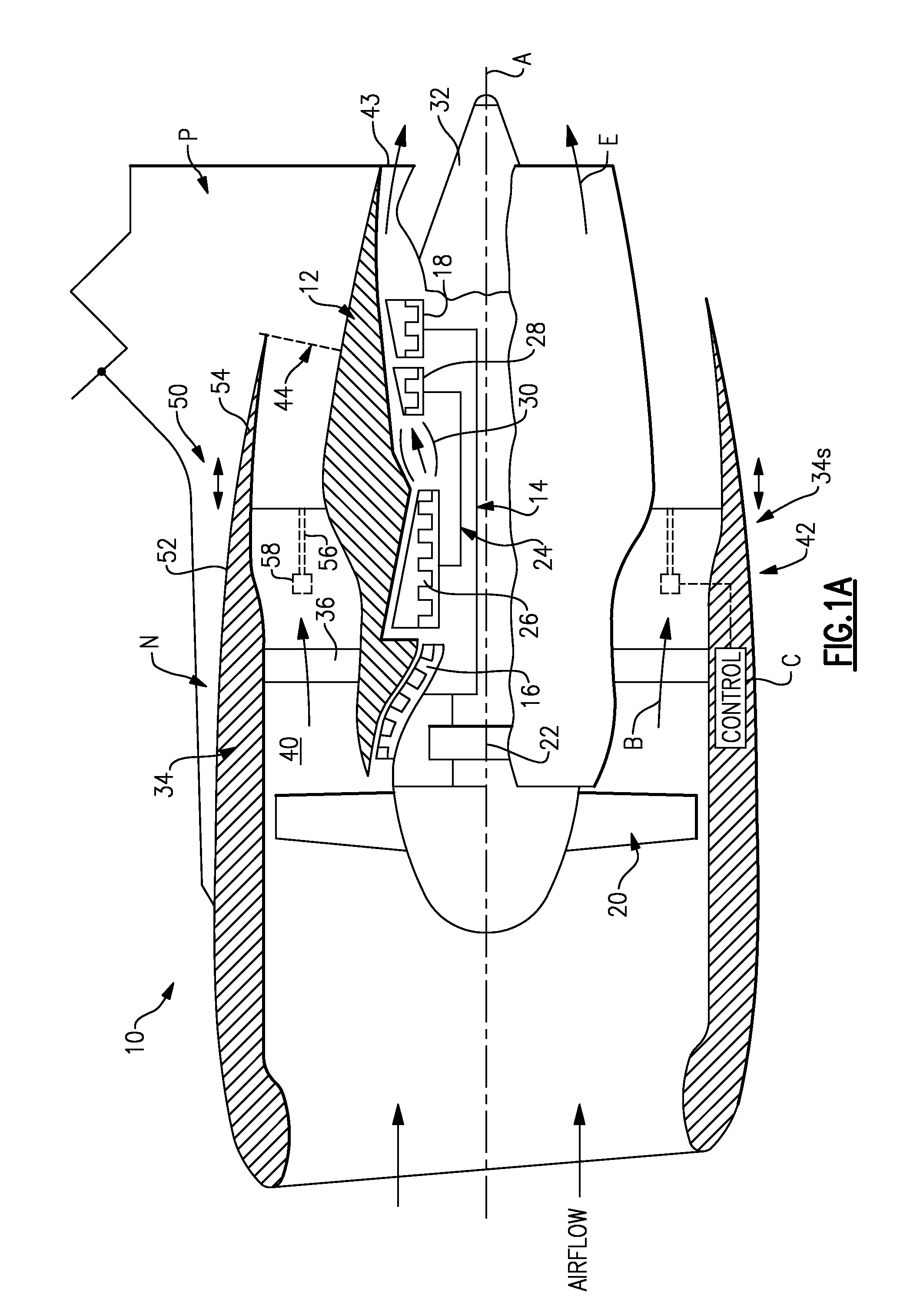
FIG. 1A illustrates a general partial fragmentary schematic view of a gas turbofan engine 10 suspended from an engine pylon P within an engine nacelle assembly N as is typical of an aircraft designed for subsonic operation.
The turbofan engine 10 includes a core engine within a core nacelle 12 that houses a low spool 14 and high spool 24. The low spool 14 includes a low pressure compressor 16 and low pressure turbine 18. The low spool 14 drives a fan section 20 through a gear train 22. The high spool 24 includes a high pressure compressor 26 and high pressure turbine 28. A combustor 30 is arranged between the high pressure compressor 26 and high pressure turbine 28. The low and high spools 14, 24 rotate about an engine axis of rotation A.
The engine 10 is preferably a high-bypass geared aircraft engine. In one disclosed, non-limiting embodiment, the engine 10 bypass ratio is greater than about six (6), with an example embodiment being greater than ten (10), the gear train 22 is an epicyclic gear train such as a planetary gear system or other gear system with a gear reduction ratio of greater than about 2.3 and the low pressure turbine 18 has a pressure ratio that is greater than about 5. In one disclosed embodiment, the engine 10 bypass ratio is greater than about ten (10:1), the turbofan diameter is significantly larger than that of the low pressure compressor 16, and the low pressure turbine 18 has a pressure ratio that is greater than about 5:1. Low pressure turbine 18 pressure ratio is pressure measured prior to inlet of low pressure turbine 18 as related to the pressure at the outlet of the low pressure turbine 18 prior to exhaust nozzle. The gear train 22 may be an epicycle gear train such as a planetary gear system or other gear system with a gear reduction ratio of greater than about 2.5:1. It should be understood, however, that the above parameters are only exemplary of one embodiment of a geared architecture engine and that the present invention is applicable to other gas turbine engines including direct drive turbofans.
Airflow enters a fan nacelle 34, which at least partially surrounds the core nacelle 12. The fan section 20 communicates airflow into the core nacelle 12 to power the low pressure compressor 16 and the high pressure compressor 26. Core airflow compressed by the low pressure compressor 16 and the high pressure compressor 26 is mixed with the fuel in the combustor 30 and expanded over the high pressure turbine 28 and low pressure turbine 18. The turbines 28, 18 are coupled for rotation with, respective, spools 24, 14 to rotationally drive the compressors 26, 16 and through the gear train 22, the fan section 20 in response to the expansion. A core engine exhaust E exits the core nacelle 12 through a core nozzle 43 defined between the core nacelle 12 and a tail cone 32.
The core nacelle 12 is supported within the fan nacelle 34 by structure 36 often generically referred to as Fan Exit Guide Vanes (FEGVs). A bypass flow path 40 is defined between the core nacelle 12 and the fan nacelle 34. The engine 10 generates a high bypass flow arrangement with a bypass ratio in which approximately 80 percent of the airflow entering the fan nacelle 34 becomes bypass flow B. The bypass flow B communicates through the generally annular fan bypass flow path 40 and is discharged from the engine 10 through a fan variable area nozzle (VAFN) 42 which defines a fan nozzle exit area 44 between the fan nacelle 34 and the core nacelle 12 at a fan nacelle end segment 34S of the fan nacelle 34 downstream of the fan section 20.
Thrust is a function of density, velocity, and area. One or more of these parameters can be manipulated to vary the amount and direction of thrust provided by the bypass flow B. The Variable Area Fan Nozzle ("VAFN") 42 operates to effectively vary the area of the fan nozzle exit area 44 to selectively adjust the pressure ratio of the bypass flow B in response to a controller C. Low pressure ratio turbofans are desirable for their high propulsive efficiency. However, low pressure ratio fans may be inherently susceptible to fan stability/flutter problems at low power and low flight speeds. The VAFN 42 allows the engine to change to a more favorable fan operating line at low power, avoiding the instability region, and still provide the relatively smaller nozzle area necessary to obtain a high-efficiency fan operating line at cruise.
A significant amount of thrust is provided by the bypass flow B due to the high bypass ratio. The fan section 20 of the engine 10 is designed for a particular flight condition--typically cruise at about 0.8 Mach and about 35,000 feet. The flight condition of 0.8 Mach and 35,000 ft, with the engine at its best fuel consumption--also known as "bucket cruise Thrust Specific Fuel Consumption (`TSFC`)"--is the industry standard parameter of lbm of fuel being burned divided by lbf of thrust the engine produces at that minimum point. "Low fan pressure ratio" is the pressure ratio across the fan blade alone, without the Fan Exit Guide Vane ("FEGV") system 36. The low fan pressure ratio as disclosed herein according to one non-limiting embodiment is less than about 1.45. "Low corrected fan tip speed" is the actual fan tip speed in ft/sec divided by an industry standard temperature correction of [(Tambient deg R)/518.7)^0.5]. The "Low corrected fan tip speed" as disclosed herein according to one non-limiting embodiment is less than about 1150 ft/second.
As the fan blades within the fan section 20 are efficiently designed at a particular fixed stagger angle for an efficient cruise condition, the VAFN 42 is operated to effectively vary the fan nozzle exit area 44 to adjust fan bypass air flow such that the angle of attack or incidence on the fan blades is maintained close to the design incidence for efficient engine operation at other flight conditions, such as landing and takeoff to thus provide optimized engine operation over a range of flight conditions with respect to performance and other operational parameters such as noise levels.
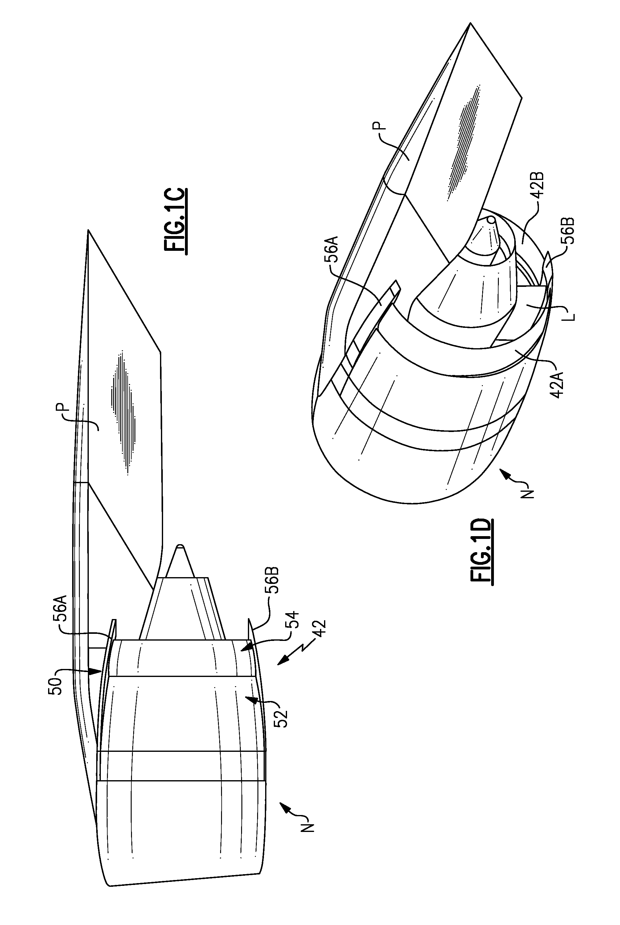
The VAFN 42 is separated into at least two sectors 42A-42B (FIG. 1B) defined between the pylon P and a lower Bi-Fi splitter L which typically interconnects a larger diameter fan duct reverser cowl and a smaller diameter core cowl (FIGS. 1C and 1D). Each of the at least two sectors 42A-42B are independently adjustable to asymmetrically vary the fan nozzle exit area 44 to generate vectored thrust. It should be understood that although two segments are illustrated, any number of segments may alternatively or additionally be provided.
In operation, the VAFN 42 communicates with a controller C or the like to adjust the fan nozzle exit area 44 in a symmetrical and asymmetrical manner. Other control systems including an engine controller or aircraft flight control system may also be usable with the present invention. By adjusting the entire periphery of the VAFN 42 symmetrically in which all sectors are moved uniformly, thrust efficiency and fuel economy are maximized during each flight condition. By separately adjusting the circumferential sectors 42A-42B of the VAFN 42 to provide an asymmetrical fan nozzle exit area 44, engine bypass flow is selectively vectored to provide, for example only, trim balance or thrust controlled maneuvering enhanced ground operations or short field performance.
The VAFN 42 generally includes an auxiliary port assembly 50 having a first fan nacelle section 52 and a second fan nacelle section 54 movably mounted relative the first fan nacelle section 52. The second fan nacelle section 54 axially slides along the engine axis A relative the fixed first fan nacelle section 52 to change the effective area of the fan nozzle exit area 44. The second fan nacelle section 54 slides aftward upon a track fairing 56A, 56B (illustrated schematically in FIGS. 1C and 1D) in response to an actuator 58 (illustrated schematically). The track fairing 56A, 56B extend from the first fan nacelle section 52 adjacent the respective pylon P and the lower Bi-Fi splitter L (FIG. 1D).
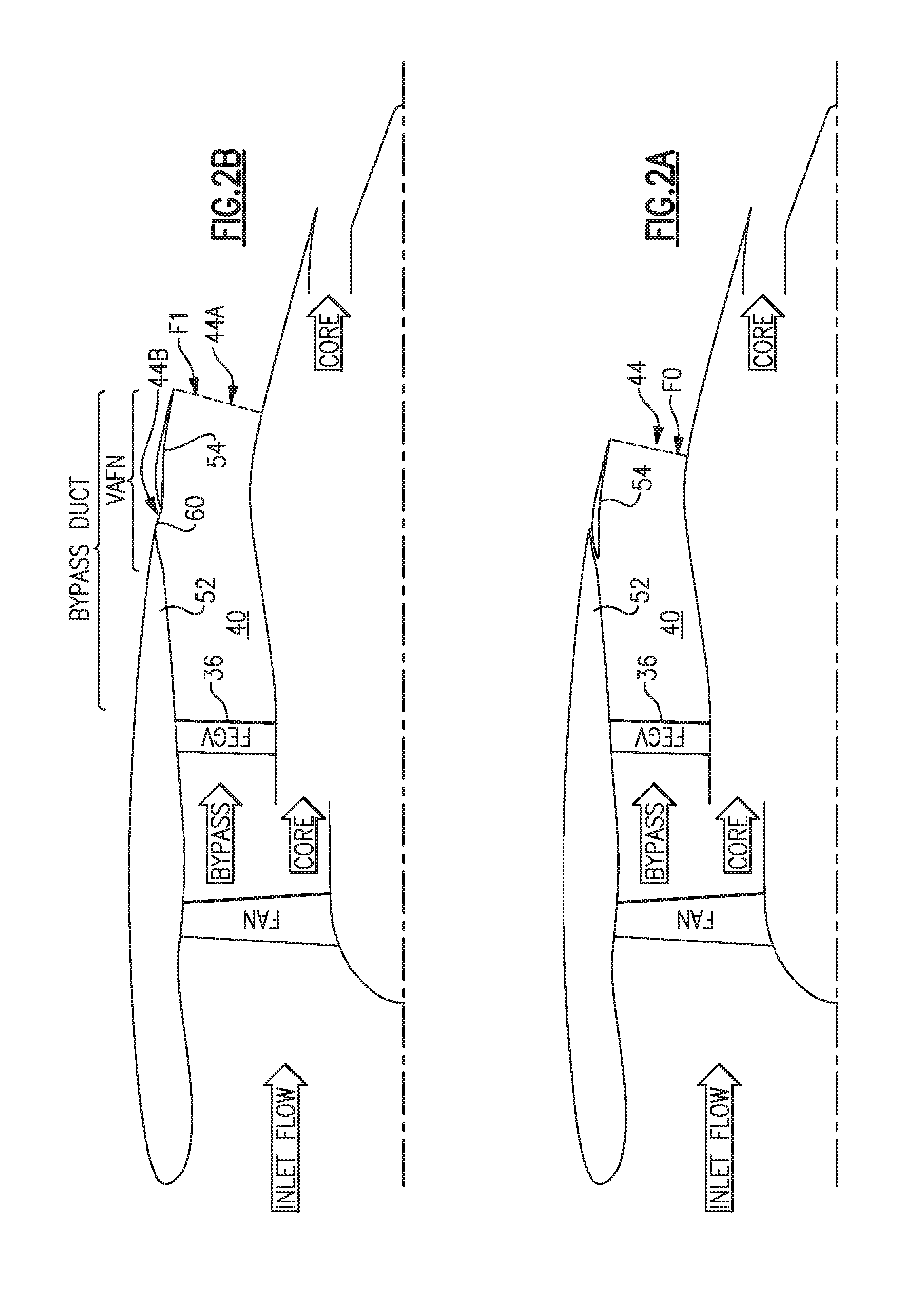
The VAFN 42 changes the physical area and geometry of the bypass flow path 40 during particular flight conditions. The bypass flow B is effectively altered by sliding of the second fan nacelle section 54 relative the first fan nacelle section 52 between a closed position (FIG. 2A) and an open position (FIG. 2B). The auxiliary port assembly 50 is closed by positioning the second fan nacelle section 54 in-line with the first fan nacelle section 52 to define the fan nozzle exit area 44 as exit area F0 (FIG. 2A).
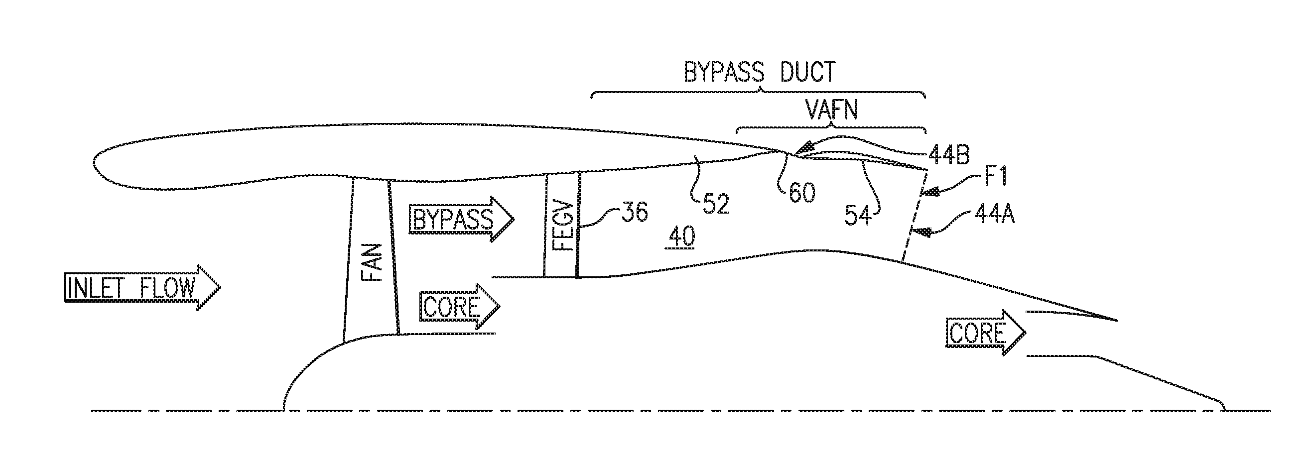
The VAFN 42 is opened by moving the second fan nacelle section 54 aftward along the track fairing 56A, 56B away from the first fan nacelle section 52 to open an auxiliary port 60 which extends between the open second fan nacelle section 54 relative the first fan nacelle section 52 to essentially provide an increased fan nozzle exit area 44 exit area F1. That is, the exit area F1 with the port 60 is greater than exit area F0 (FIG. 2B).
In one disclosed embodiment, the auxiliary port 60 is incorporated into the exhaust system of a high bypass ratio commercial turbofan engine within the bypass duct aft of the Fan Exit Guide Vanes (FEGVs; FIGS. 2A, 2B). The auxiliary port 60 is located in the aft section of the bypass duct outer wall.
Referring to FIG. 3, the bypass duct area distribution, the effective area increase vs. translation (FIG. 4), area distribution (FIG. 5), and auxiliary port 60 location (FIG. 6A) and wall curvatures (FIG. 6B-6C) are tailored to provide a proper flow-field that allows the auxiliary port 60 to obtain the required additional effective exit area. The auxiliary port 60 will essentially double the effective area gain due to translation. The auxiliary port 60 provides a relatively low weight method of providing increased exit area to control the fan operating line without causing high system losses or unacceptable aircraft installation issues. By tailoring the bypass duct area distribution and outer wall curvature, the desired maximum effective area increase is achieved before the stroke of the auxiliary port 60 reaches its effective area increase limit.
The auxiliary port exit plane 44B (defined as the plane between the stationary section's trailing edge and the moving sections leading edge) initially has an opening in which the exit plane normal vector is near-axial, but as the stroke increases, the normal vector becomes more inclined and approaches a near-radial vector. Once the exit plane normal has become near-radial, the maximum auxiliary port effectiveness has been reached. Once this point is reached, the rate of the effective area vs. translation changes from steep slope of the "well designed port" the shallow rate of the "main nozzle only", since additional area will be provided through the main nozzle 44A due to the inward slope of the core nacelle 12. A well designed auxiliary port nozzle will achieve approximately +25% effective area before the port effectiveness limit is reached. That is, there is a limited range of stroke in which the auxiliary port doubles the rate of additional effectiveness. Outside of this range, the rate of additional effectiveness may be equivalent to a translating nozzle that has no auxiliary port. Or put another way, the auxiliary port reduces the stroke necessary for a pure translating nozzle to achieve a desired effective area.
Referring to FIG. 5, the cross-sectional area at the auxiliary port 60 is greater than the maximum required effective area of the VAFN 42 and the bypass duct area distribution is tailored to ensure the duct cross-sectional area forward of the auxiliary port 60 is greater than the port opening cross-sectional area. This avoids a situation where an upstream internal cross-section becomes the controlling flow area (i.e. is smaller than the exit area), which can lead to operational limits and structural issues.
Referring to FIG. 6A, the auxiliary port 60 in the disclosed embodiment, is located no more forward than 0.1 DEL_X/L_DUCT defined from a point D at the largest radius Rmax of the annular fan bypass flow path 40 defined by the second fan nacelle section 54. Rmax is defined through point D and perpendicular to the engine axis A. Point D in the disclosed non limiting embodiment is located on an inner wall surface 541 of the second fan nacelle section 54 when the second fan nacelle section 54 is in a closed position. DEL_X is the axial distance to the forward most point of the auxiliary port 60 from Rmax. L_DUCT is the overall axial length of the annular fan bypass flow path 40. The angle between the mean port line and the fan duct outer wall is relatively low to provide well-behaved, low loss exit flow. In the disclosed embodiment, the auxiliary port 60 entrance angle (Theta_in) relative to the fan bypass duct OD wall, is less than 20 degrees (FIG. 6B) while the outer VAFN surface has an R_ARC/CHORD>0.7 where R_ARC is a radial distance from the engine axis A to a radial outer wall surface 54O of the second fan nacelle section 54 and CHORD is the chord length of the second fan nacelle section 54. (FIG. 6C). The curvature of the outer wall surface 54O near the auxiliary port 60 promotes flow through the auxiliary port 60. In one disclosed embodiment, the stroke of the second fan nacelle section 54 necessary to obtain an additional 20% effective exit area is approximately 8.4 inches.
In operation, the VAFN 42 communicates with the controller C to move the second fan nacelle section 54 relative the first fan nacelle section 52 of the auxiliary port assembly 50 to effectively vary the area defined by the fan nozzle exit area 44. Various control systems including an engine controller or an aircraft flight control system may also be usable with the present invention. By adjusting the axial position of the entire periphery of the second fan nacelle section 54 in which all sectors are moved simultaneously, engine thrust and fuel economy are maximized during each flight regime by varying the fan nozzle exit area. By separately adjusting the sectors of the second fan nacelle section 54 to provide an asymmetrical fan nozzle exit area 44, engine bypass flow is selectively vectored to provide, for example only, trim balance, thrust controlled maneuvering, enhanced ground operations and short field performance.
The foregoing description is exemplary rather than defined by the limitations within. Many modifications and variations of the present invention are possible in light of the above teachings. The preferred embodiments of this invention have been disclosed, however, one of ordinary skill in the art would recognize that certain modifications would come within the scope of this invention. It is, therefore, to be understood that within the scope of the appended claims, the invention may be practiced otherwise than as specifically described. For that reason the following claims should be studied to determine the true scope and content of this invention.
* * * * *
References
D00000
D00001
D00002
D00003
D00004
D00005
D00006
D00007
D00008
XML
uspto.report is an independent third-party trademark research tool that is not affiliated, endorsed, or sponsored by the United States Patent and Trademark Office (USPTO) or any other governmental organization. The information provided by uspto.report is based on publicly available data at the time of writing and is intended for informational purposes only.
While we strive to provide accurate and up-to-date information, we do not guarantee the accuracy, completeness, reliability, or suitability of the information displayed on this site. The use of this site is at your own risk. Any reliance you place on such information is therefore strictly at your own risk.
All official trademark data, including owner information, should be verified by visiting the official USPTO website at www.uspto.gov. This site is not intended to replace professional legal advice and should not be used as a substitute for consulting with a legal professional who is knowledgeable about trademark law.