Vacuum commutation apparatus and methods
Ingole , et al. J
U.S. patent number 10,167,156 [Application Number 15/217,677] was granted by the patent office on 2019-01-01 for vacuum commutation apparatus and methods. This patent grant is currently assigned to Curt G. Joa, Inc.. The grantee listed for this patent is CURT G. JOA, INC.. Invention is credited to Sudeep Ingole, Jon Allen Pelland.


View All Diagrams
| United States Patent | 10,167,156 |
| Ingole , et al. | January 1, 2019 |
Vacuum commutation apparatus and methods
Abstract
The present invention provides a method and apparatus for transporting a discrete element. A preferably rotatably driven vacuum commutation zone (or internal vacuum manifold), preferably internal to a preferably independently driven porous vacuum roll or drum is disclosed. The vacuum manifold applies vacuum through pores in the driven porous vacuum roll or puck in order to hold material against an external surface of the vacuum roll or puck. By independently controlling the vacuum commutation zone and the driven porous surface, unique motion profiles of the vacuum commutation zone relative to the driven porous surface can be provided. Micro vacuum commutation port structures are also disclosed.
| Inventors: | Ingole; Sudeep (Sheboygan, WI), Pelland; Jon Allen (Sheboygan, WI) | ||||||||||
|---|---|---|---|---|---|---|---|---|---|---|---|
| Applicant: |
|
||||||||||
| Assignee: | Curt G. Joa, Inc. (Sheboygan
Falls, WI) |
||||||||||
| Family ID: | 57835888 | ||||||||||
| Appl. No.: | 15/217,677 | ||||||||||
| Filed: | July 22, 2016 |
Prior Publication Data
| Document Identifier | Publication Date | |
|---|---|---|
| US 20170020741 A1 | Jan 26, 2017 | |
Related U.S. Patent Documents
| Application Number | Filing Date | Patent Number | Issue Date | ||
|---|---|---|---|---|---|
| 62196736 | Jul 24, 2015 | ||||
| 62248155 | Oct 29, 2015 | ||||
| Current U.S. Class: | 1/1 |
| Current CPC Class: | B65H 27/00 (20130101); B65H 39/14 (20130101); B65G 47/848 (20130101); B65G 39/02 (20130101); B65G 29/02 (20130101); B65G 47/915 (20130101); B65H 5/226 (20130101); B65H 29/243 (20130101); B65H 20/12 (20130101); B65H 2404/1363 (20130101); B65H 2301/4473 (20130101); B65H 2406/332 (20130101); B65H 2404/1362 (20130101); B65H 2406/361 (20130101); B65H 2801/57 (20130101); B65H 2301/4473 (20130101); B65H 2220/02 (20130101) |
| Current International Class: | B65H 20/12 (20060101); B65G 29/02 (20060101); B65G 39/02 (20060101); B65G 47/91 (20060101); B65G 47/84 (20060101); B65H 39/14 (20060101) |
References Cited [Referenced By]
U.S. Patent Documents
| 135145 | January 1873 | Murphy |
| 293353 | February 1884 | Purvis |
| 312257 | February 1885 | Cotton et al. |
| 410123 | August 1889 | Stilwell |
| 432742 | July 1890 | Stanley |
| 643821 | February 1900 | Howlett |
| 1393524 | October 1921 | Grupe |
| 1431315 | October 1922 | Le Moine |
| 1605842 | November 1926 | Jones |
| 1686595 | October 1928 | Belluche |
| 1957651 | May 1934 | Joa |
| 2009857 | July 1935 | Potdevin |
| 2054832 | September 1936 | Potdevin |
| 2117432 | May 1938 | Linscott |
| 2128746 | August 1938 | Joa |
| 2131808 | October 1938 | Joa |
| 2164408 | July 1939 | Joa |
| 2167179 | July 1939 | Joa |
| 2171741 | September 1939 | Cohn et al. |
| 2213431 | September 1940 | Joa |
| 2254290 | September 1941 | Joa |
| 2254291 | September 1941 | Joa |
| 2282477 | May 1942 | Joa |
| 2286096 | June 1942 | Joa |
| 2296931 | September 1942 | Joa |
| 2304571 | December 1942 | Joa |
| 2324930 | July 1943 | Joa |
| 2345937 | April 1944 | Joa |
| 2466240 | April 1949 | Joa |
| 2481929 | September 1949 | Joa |
| 2510229 | June 1950 | Joa |
| 2540844 | February 1951 | Strauss |
| 2584002 | January 1952 | Elser et al. |
| 2591359 | April 1952 | Joa |
| 2618816 | November 1952 | Joa |
| 2627859 | February 1953 | Hargrave |
| 2695025 | November 1954 | Andrews |
| 2702406 | February 1955 | Reed |
| 2721554 | October 1955 | Joa |
| 2730144 | January 1956 | Joa |
| 2772611 | December 1956 | Heywood |
| 2780253 | February 1957 | Joa |
| 2785609 | March 1957 | Billeb |
| 2788786 | April 1957 | Dexter |
| 2811905 | November 1957 | Kennedy, Jr. |
| 2828745 | April 1958 | Deutz |
| 2839059 | June 1958 | Joa |
| 2842169 | July 1958 | Joa |
| 2851934 | September 1958 | Heywood |
| 2875724 | March 1959 | Joa |
| 2890700 | June 1959 | Lonberg-Holm |
| 2913862 | November 1959 | Sabee |
| 2939461 | June 1960 | Joa |
| 2939646 | June 1960 | Stone |
| 2960143 | November 1960 | Joa |
| 2990081 | June 1961 | De Neui et al. |
| 2991739 | July 1961 | Joa |
| 3016207 | January 1962 | Comstock, III |
| 3016582 | January 1962 | Joa |
| 3017795 | January 1962 | Joa |
| 3020687 | February 1962 | Joa |
| 3021135 | February 1962 | Joa |
| 3024957 | March 1962 | Pinto |
| 3053427 | September 1962 | Wasserman |
| 3054516 | September 1962 | Joa |
| 3069982 | December 1962 | Heywood et al. |
| 3075684 | January 1963 | Rothmann |
| 3086253 | April 1963 | Joa |
| 3087689 | April 1963 | Heim |
| 3089494 | May 1963 | Schwartz |
| 3091408 | May 1963 | Schoeneman |
| 3114994 | December 1963 | Joa |
| 3122293 | February 1964 | Joa |
| 3128206 | April 1964 | Dungler |
| 3203419 | August 1965 | Joa |
| 3230955 | January 1966 | Joa |
| 3268954 | August 1966 | Joa |
| 3288037 | November 1966 | Burnett |
| 3289254 | December 1966 | Joa |
| 3291131 | December 1966 | Joa |
| 3301114 | January 1967 | Joa |
| 3318608 | May 1967 | Smrekar |
| 3322589 | May 1967 | Joa |
| 3336847 | August 1967 | Durat |
| 3342184 | September 1967 | Joa |
| 3356092 | December 1967 | Joa |
| 3360103 | December 1967 | Joa |
| 3391777 | July 1968 | Joa |
| 3454442 | July 1969 | Heller, Jr. |
| 3463413 | August 1969 | Smith |
| 3470848 | October 1969 | Dreher |
| 3484275 | December 1969 | Lewicki, Jr. |
| 3502322 | March 1970 | Cran |
| 3521639 | July 1970 | Joa |
| 3526563 | September 1970 | Schott, Jr. |
| 3527123 | September 1970 | Dovey |
| 3533618 | October 1970 | Carstens |
| 3538551 | November 1970 | Joa |
| 3540641 | November 1970 | Besnyo |
| 3575170 | April 1971 | Clark |
| 3607578 | September 1971 | Berg et al. |
| 3635462 | January 1972 | Joa |
| 3656741 | April 1972 | Macke et al. |
| 3666611 | May 1972 | Joa |
| 3673021 | June 1972 | Joa |
| 3685818 | August 1972 | Burger et al. |
| 3728191 | April 1973 | Wierzba et al. |
| 3745947 | July 1973 | Brocklehurst |
| 3751224 | August 1973 | Wackerle |
| 3758102 | September 1973 | Munn et al. |
| 3762542 | October 1973 | Grimes |
| 3772120 | November 1973 | Radzins |
| 3776798 | December 1973 | Milano |
| 3796360 | March 1974 | Alexeff |
| 3810344 | May 1974 | Evans et al. |
| 3811987 | May 1974 | Wilkinson et al. |
| 3816210 | June 1974 | Aoko et al. |
| 3836089 | September 1974 | Riemersma |
| 3847710 | November 1974 | Blomqvist et al. |
| 3854917 | December 1974 | McKinney et al. |
| 3883389 | May 1975 | Schott, Jr. |
| 3888400 | June 1975 | Wiig |
| 3901238 | August 1975 | Geller et al. |
| 3903768 | September 1975 | Amberg et al. |
| 3904147 | September 1975 | Taitel et al. |
| 3918968 | November 1975 | Coast |
| 3921481 | November 1975 | Fleetwod |
| 3941038 | March 1976 | Bishop |
| 3960646 | June 1976 | Wiedamann |
| 3988194 | October 1976 | Babcock et al. |
| 3991994 | November 1976 | Farish |
| 4002005 | January 1977 | Mueller et al. |
| 4003298 | January 1977 | Schott, Jr. |
| 4009626 | March 1977 | Gressman |
| 4009814 | March 1977 | Singh |
| 4009815 | March 1977 | Ericson et al. |
| 4053150 | October 1977 | Lane |
| 4056919 | November 1977 | Hirsch |
| 4081301 | March 1978 | Buell |
| 4090516 | May 1978 | Schaar |
| 4094319 | June 1978 | Joa |
| 4103595 | August 1978 | Corse |
| 4106974 | August 1978 | Hirsch |
| 4108584 | August 1978 | Radzins et al. |
| 4136535 | January 1979 | Audas |
| 4141193 | February 1979 | Joa |
| 4141509 | February 1979 | Radzins |
| 4142626 | March 1979 | Bradley |
| 4157934 | June 1979 | Ryan et al. |
| 4165666 | August 1979 | Johnson et al. |
| 4168776 | September 1979 | Hoeboer |
| 4171239 | October 1979 | Hirsch et al. |
| 4205679 | June 1980 | Repke et al. |
| 4208230 | June 1980 | Magarian |
| 4213356 | July 1980 | Armitage |
| 4215827 | August 1980 | Roberts et al. |
| 4220237 | September 1980 | Mohn |
| 4222533 | September 1980 | Pongracz |
| 4223822 | September 1980 | Clitheroe |
| 4231129 | November 1980 | Winch |
| 4234157 | November 1980 | Hodgeman et al. |
| 4236955 | December 1980 | Prittie |
| 4275510 | June 1981 | George |
| 4284454 | August 1981 | Joa |
| 4297157 | October 1981 | Van Vilet |
| 4307800 | December 1981 | Joa |
| 4316756 | February 1982 | Wilson |
| 4325519 | April 1982 | McLean |
| 4331418 | May 1982 | Klebe |
| 4342206 | August 1982 | Rommel |
| 4349140 | September 1982 | Passafiume |
| 4364787 | December 1982 | Radzins |
| 4374576 | February 1983 | Ryan |
| 4379008 | April 1983 | Gross et al. |
| 4394898 | July 1983 | Campbell |
| 4411721 | October 1983 | Wishart |
| 4426897 | January 1984 | Littleton |
| 4452597 | June 1984 | Achelpohl |
| 4479836 | October 1984 | Dickover et al. |
| 4492608 | January 1985 | Hirsch et al. |
| 4501098 | February 1985 | Gregory |
| 4508528 | April 1985 | Hirsch et al. |
| 4522853 | June 1985 | Szonn et al. |
| 4543152 | September 1985 | Nozaka |
| 4551191 | November 1985 | Kock et al. |
| 4578052 | March 1986 | Engel et al. |
| 4578133 | March 1986 | Oshefsky et al. |
| 4586199 | May 1986 | Birring |
| 4587790 | May 1986 | Muller |
| 4589945 | May 1986 | Polit |
| 4603800 | August 1986 | Focke et al. |
| 4606964 | August 1986 | Wideman |
| 4608115 | August 1986 | Schroth et al. |
| 4610681 | September 1986 | Strohbeen et al. |
| 4610682 | September 1986 | Kopp |
| 4614076 | September 1986 | Rathemacher |
| 4619357 | October 1986 | Radzins et al. |
| 4625612 | December 1986 | Oliver |
| 4634482 | January 1987 | Lammers |
| 4641381 | February 1987 | Heran et al. |
| 4642150 | February 1987 | Stemmler |
| 4642839 | February 1987 | Urban |
| 4650173 | March 1987 | Johnson et al. |
| 4650406 | March 1987 | Peters |
| 4650530 | March 1987 | Mahoney et al. |
| 4663220 | May 1987 | Wisneski et al. |
| 4672705 | June 1987 | Bors et al. |
| 4675016 | June 1987 | Meuli et al. |
| 4675062 | June 1987 | Instance |
| 4675068 | June 1987 | Lundmark |
| 4686136 | August 1987 | Homonoff et al. |
| 4693056 | September 1987 | Raszewski |
| 4701239 | October 1987 | Craig |
| 4707970 | November 1987 | Labombarde et al. |
| 4720415 | January 1988 | Vander Wielen et al. |
| 4723698 | February 1988 | Schoonderbeek |
| 4726725 | February 1988 | Baker et al. |
| 4726874 | February 1988 | Van Vliet |
| 4726876 | February 1988 | Tomsovic, Jr. |
| 4743241 | May 1988 | Igaue et al. |
| 4751997 | June 1988 | Hirsch |
| 4753429 | June 1988 | Irvine et al. |
| 4756141 | July 1988 | Hirsch et al. |
| 4764325 | August 1988 | Angstadt |
| 4765780 | August 1988 | Angstadt |
| 4776920 | October 1988 | Ryan |
| 4777513 | October 1988 | Nelson |
| 4782647 | November 1988 | Williams et al. |
| 4785986 | November 1988 | Daane et al. |
| 4795416 | January 1989 | Cogswell et al. |
| 4795451 | January 1989 | Buckley |
| 4795510 | January 1989 | Wittrock et al. |
| 4798353 | January 1989 | Peugh |
| 4801345 | January 1989 | Dussaud et al. |
| 4802570 | February 1989 | Hirsch et al. |
| 4826499 | May 1989 | Ahr |
| 4840609 | June 1989 | Jones et al. |
| 4845964 | July 1989 | Bors et al. |
| 4864802 | September 1989 | D'Angelo |
| 4873813 | October 1989 | Labombarde et al. |
| 4880102 | November 1989 | Indrebo |
| 4888231 | December 1989 | Angstadt |
| 4892536 | January 1990 | Des Marais et al. |
| 4904440 | February 1990 | Angstadt |
| 4908175 | March 1990 | Angstadt |
| 4909019 | March 1990 | Delacretaz et al. |
| 4909697 | March 1990 | Bernard et al. |
| 4915767 | April 1990 | Rajala et al. |
| 4917746 | April 1990 | Kons |
| 4925520 | May 1990 | Beaudoin et al. |
| 4927322 | May 1990 | Schweizer et al. |
| 4927486 | May 1990 | Fattal et al. |
| 4927582 | May 1990 | Bryson |
| 4937887 | July 1990 | Schreiner |
| 4963072 | October 1990 | Miley et al. |
| 4987940 | January 1991 | Straub et al. |
| 4994010 | February 1991 | Doderer-Winkler |
| 5000806 | March 1991 | Merkatoris et al. |
| 5007522 | April 1991 | Focke et al. |
| 5021111 | June 1991 | Swenson |
| 5025910 | June 1991 | Lasure et al. |
| 5029505 | July 1991 | Holliday |
| 5045039 | September 1991 | Bay |
| 5045135 | September 1991 | Meissner et al. |
| 5062597 | November 1991 | Martin et al. |
| 5064179 | November 1991 | Martin |
| 5064492 | November 1991 | Friesch |
| 5080741 | January 1992 | Nomura et al. |
| 5094658 | March 1992 | Smithe et al. |
| 5096532 | March 1992 | Neuwirth et al. |
| 5108017 | April 1992 | Adamski, Jr. et al. |
| 5109767 | May 1992 | Nyfeler et al. |
| 5110403 | May 1992 | Ehlert |
| 5114392 | May 1992 | McAdam et al. |
| 5127981 | July 1992 | Straub et al. |
| 5131525 | July 1992 | Musschoot |
| 5131901 | July 1992 | Moll |
| 5133511 | July 1992 | Mack |
| 5137758 | August 1992 | Kistner |
| 5147487 | September 1992 | Nomura et al. |
| 5163594 | November 1992 | Meyer |
| 5171239 | December 1992 | Igaue et al. |
| 5176244 | January 1993 | Radzins et al. |
| 5183252 | February 1993 | Wolber et al. |
| 5188627 | February 1993 | Igaue et al. |
| 5190234 | March 1993 | Ezekiel |
| 5195684 | March 1993 | Radzins |
| 5203043 | April 1993 | Riedel |
| 5213645 | May 1993 | Nomura et al. |
| 5222422 | June 1993 | Benner, Jr. et al. |
| 5223069 | June 1993 | Tokuno et al. |
| 5226992 | July 1993 | Morman |
| 5246433 | September 1993 | Hasse et al. |
| 5252228 | October 1993 | Stokes |
| 5267933 | December 1993 | Precoma |
| 5273228 | December 1993 | Yoshida |
| 5275076 | January 1994 | Greenwalt |
| 5275676 | January 1994 | Rooyakkers et al. |
| 5308345 | May 1994 | Herrin |
| 5328438 | July 1994 | Crowley |
| 5334446 | August 1994 | Quantrille et al. |
| 5340424 | August 1994 | Matsushita |
| 5353909 | October 1994 | Mukai |
| 5368893 | November 1994 | Sommer et al. |
| 5389173 | February 1995 | Merkotoris et al. |
| 5393360 | February 1995 | Bridges et al. |
| 5407507 | April 1995 | Ball |
| 5407513 | April 1995 | Hayden et al. |
| 5410857 | May 1995 | Utley |
| 5415649 | May 1995 | Watanabe et al. |
| 5417132 | May 1995 | Cox et al. |
| 5421924 | June 1995 | Ziegelhoffer et al. |
| 5424025 | June 1995 | Hanschen et al. |
| 5429576 | July 1995 | Doderer-Winkler |
| 5435802 | July 1995 | Kober |
| 5435971 | July 1995 | Dyckman |
| 5449353 | September 1995 | Watanabe et al. |
| 5464401 | November 1995 | Hasse et al. |
| 5472153 | December 1995 | Crowley et al. |
| 5486253 | January 1996 | Otruba |
| 5494622 | February 1996 | Heath et al. |
| 5500075 | March 1996 | Herrmann |
| 5513936 | May 1996 | Dean |
| 5516392 | May 1996 | Bridges et al. |
| 5518566 | May 1996 | Bridges et al. |
| 5525175 | June 1996 | Blenke et al. |
| 5531850 | July 1996 | Herrmann |
| 5540647 | July 1996 | Weiermann et al. |
| 5540796 | July 1996 | Fries |
| 5545275 | August 1996 | Herrin et al. |
| 5545285 | August 1996 | Johnson |
| 5552013 | September 1996 | Ehlert et al. |
| 5555786 | September 1996 | Fuller |
| 5556246 | September 1996 | Broshi |
| 5556360 | September 1996 | Kober et al. |
| 5556504 | September 1996 | Rajala et al. |
| 5560793 | October 1996 | Ruscher et al. |
| 5575187 | November 1996 | Dieterlen |
| 5582497 | December 1996 | Noguchi |
| 5586964 | December 1996 | Chase |
| 5602747 | February 1997 | Rajala |
| 5603794 | February 1997 | Thomas |
| 5624420 | April 1997 | Bridges et al. |
| 5624428 | April 1997 | Sauer |
| 5628738 | May 1997 | Suekane |
| 5634917 | June 1997 | Fujioka et al. |
| 5636500 | June 1997 | Gould |
| 5643165 | July 1997 | Klekamp |
| 5643396 | July 1997 | Rajala et al. |
| 5645543 | July 1997 | Nomura et al. |
| 5659229 | August 1997 | Rajala |
| 5660657 | August 1997 | Rajala et al. |
| 5660665 | August 1997 | Jalonen |
| 5683376 | November 1997 | Kato et al. |
| 5683531 | November 1997 | Roessler et al. |
| 5685873 | November 1997 | Bruemmer |
| RE35687 | December 1997 | Igaue et al. |
| 5693165 | December 1997 | Schmitz |
| 5699653 | December 1997 | Hartman et al. |
| 5705013 | January 1998 | Nease |
| 5707470 | January 1998 | Rajala et al. |
| 5711832 | January 1998 | Glaug et al. |
| 5725518 | March 1998 | Coates |
| 5725714 | March 1998 | Fujioka |
| 5743994 | April 1998 | Roessler et al. |
| 5745922 | May 1998 | Rajala et al. |
| 5746869 | May 1998 | Hayden et al. |
| 5749989 | May 1998 | Linman et al. |
| 5759340 | June 1998 | Boothe et al. |
| 5766389 | June 1998 | Brandon et al. |
| 5766411 | June 1998 | Wilson |
| 5779689 | July 1998 | Pfeifer et al. |
| 5788797 | August 1998 | Herrin et al. |
| 5817199 | October 1998 | Brennecke et al. |
| 5827259 | October 1998 | Laux et al. |
| 5829164 | November 1998 | Kotischke |
| 5836931 | November 1998 | Toyoda et al. |
| 5858012 | January 1999 | Yamaki et al. |
| 5865393 | February 1999 | Kreft et al. |
| 5868727 | February 1999 | Barr et al. |
| 5876027 | March 1999 | Fukui et al. |
| 5876792 | March 1999 | Caldwell |
| 5879500 | March 1999 | Herrin et al. |
| 5897291 | April 1999 | Gerwe et al. |
| 5902222 | May 1999 | Wessman |
| 5902431 | May 1999 | Wilkinson et al. |
| 5904675 | May 1999 | Laux et al. |
| 5932039 | August 1999 | Popp et al. |
| 5935367 | August 1999 | Hollenbeck |
| 5938193 | August 1999 | Bluemle et al. |
| 5938652 | August 1999 | Sauer |
| 5964390 | October 1999 | Borresen et al. |
| 5964970 | October 1999 | Woolwine et al. |
| 5971134 | October 1999 | Trefz et al. |
| 5983764 | November 1999 | Hillebrand |
| 6009781 | January 2000 | McNeil |
| 6022443 | February 2000 | Rajala et al. |
| 6036805 | March 2000 | McNichols |
| 6043836 | March 2000 | Kerr et al. |
| 6050517 | April 2000 | Dobrescu et al. |
| 6074110 | June 2000 | Verlinden et al. |
| 6076442 | June 2000 | Arterburn et al. |
| 6080909 | June 2000 | Osterdahl et al. |
| 6098249 | August 2000 | Toney et al. |
| 6123792 | September 2000 | Samida et al. |
| 6138436 | October 2000 | Malin et al. |
| 6142048 | November 2000 | Bradatsch et al. |
| 6171432 | January 2001 | Brisebois |
| 6183576 | February 2001 | Couillard et al. |
| 6193054 | February 2001 | Henson et al. |
| 6193702 | February 2001 | Spencer |
| 6195850 | March 2001 | Melbye |
| 6196147 | March 2001 | Burton et al. |
| 6210386 | April 2001 | Inoue |
| 6212859 | April 2001 | Bielik, Jr. et al. |
| 6214147 | April 2001 | Mortellite et al. |
| 6217274 | April 2001 | Svyatsky et al. |
| 6250048 | June 2001 | Linkiewicz |
| 6264639 | July 2001 | Sauer |
| 6264784 | July 2001 | Menard et al. |
| 6276421 | August 2001 | Valenti et al. |
| 6276587 | August 2001 | Borresen |
| 6280373 | August 2001 | Lanvin |
| 6284081 | September 2001 | Vogt et al. |
| 6287409 | September 2001 | Stephany |
| 6305260 | October 2001 | Truttmann et al. |
| 6306122 | October 2001 | Narawa et al. |
| 6309336 | October 2001 | Muessig et al. |
| 6312420 | November 2001 | Sasaki et al. |
| 6314333 | November 2001 | Rajala et al. |
| 6315022 | November 2001 | Herrin et al. |
| 6319347 | November 2001 | Rajala |
| 6336921 | January 2002 | Kato et al. |
| 6336922 | January 2002 | VanGompel et al. |
| 6336923 | January 2002 | Fujioka et al. |
| 6358350 | March 2002 | Glaug et al. |
| 6369291 | April 2002 | Uchimoto et al. |
| 6375769 | April 2002 | Quereshi et al. |
| 6391013 | May 2002 | Suzuki et al. |
| 6416697 | July 2002 | Venturino et al. |
| 6425430 | July 2002 | Ward et al. |
| 6431038 | August 2002 | Couturier |
| 6440246 | August 2002 | Vogt et al. |
| 6443389 | September 2002 | Palone |
| 6446795 | September 2002 | Allen et al. |
| 6446955 | September 2002 | Janatka |
| 6473669 | October 2002 | Rajala et al. |
| 6475325 | November 2002 | Parrish et al. |
| 6478786 | November 2002 | Glaug et al. |
| 6482278 | November 2002 | McCabe et al. |
| 6494244 | December 2002 | Parrish et al. |
| 6514233 | February 2003 | Glaug |
| 6521320 | February 2003 | McCabe et al. |
| 6523595 | February 2003 | Milner et al. |
| 6524423 | February 2003 | Hilt et al. |
| 6533879 | March 2003 | Quereshi et al. |
| 6540857 | April 2003 | Coenen et al. |
| 6547909 | April 2003 | Butterworth |
| 6550517 | April 2003 | Hilt |
| 6551228 | April 2003 | Richards |
| 6551430 | April 2003 | Glaug et al. |
| 6554815 | April 2003 | Umebayashi |
| 6557466 | May 2003 | Codde et al. |
| 6569275 | May 2003 | Popp et al. |
| 6572520 | June 2003 | Blumle |
| 6581517 | June 2003 | Becker et al. |
| 6585841 | July 2003 | Popp et al. |
| 6589149 | July 2003 | VanEperen et al. |
| 6596107 | July 2003 | Stopher |
| 6596108 | July 2003 | McCabe |
| 6605172 | August 2003 | Anderson et al. |
| 6605173 | August 2003 | Glaug et al. |
| 6620276 | September 2003 | Kuntze et al. |
| 6632209 | October 2003 | Chmielewski |
| 6634269 | October 2003 | Eckstein et al. |
| 6637583 | October 2003 | Anderson |
| 6648122 | November 2003 | Hirsch et al. |
| 6649010 | November 2003 | Parrish et al. |
| 6656309 | December 2003 | Parker et al. |
| 6659150 | December 2003 | Perkins et al. |
| 6659991 | December 2003 | Suckane |
| 6675552 | January 2004 | Kunz et al. |
| 6682626 | January 2004 | Mlinar et al. |
| 6684925 | February 2004 | Nagate et al. |
| 6685130 | February 2004 | Stauber et al. |
| 6722494 | April 2004 | Nakakado |
| 6730189 | May 2004 | Franzmann |
| 6743324 | June 2004 | Hargett et al. |
| 6750466 | June 2004 | Song |
| 6758109 | July 2004 | Nakakado |
| 6766817 | July 2004 | da Silva |
| 6773006 | August 2004 | Andreyka |
| 6779426 | August 2004 | Holliday |
| 6808582 | October 2004 | Popp et al. |
| D497991 | November 2004 | Otsubo et al. |
| 6811019 | November 2004 | Christian et al. |
| 6811642 | November 2004 | Ochi |
| 6814217 | November 2004 | Blumenthal et al. |
| 6820671 | November 2004 | Calvert |
| 6823981 | November 2004 | Ogle et al. |
| 6837840 | January 2005 | Yonekawa et al. |
| 6840616 | January 2005 | Summers |
| 6869494 | March 2005 | Roessler et al. |
| 6875202 | April 2005 | Kumasaka et al. |
| 6884310 | April 2005 | Roessler et al. |
| 6893528 | May 2005 | Middelstadt et al. |
| 6913664 | July 2005 | Umebayashi et al. |
| 6913718 | July 2005 | Ducker |
| 6918404 | July 2005 | Dias da Silva |
| 6852186 | December 2005 | Matsuda et al. |
| 6976521 | December 2005 | Mlinar |
| 6978486 | December 2005 | Zhou et al. |
| 6978964 | December 2005 | Beccari |
| 7017321 | March 2006 | Salvoni |
| 7017820 | March 2006 | Brunner |
| 7045031 | May 2006 | Popp et al. |
| 7047852 | May 2006 | Franklin et al. |
| 7048725 | May 2006 | Kling et al. |
| 7066586 | June 2006 | da Silva |
| 7069970 | July 2006 | Tomsovic et al. |
| 7077393 | July 2006 | Ishida |
| 7130710 | October 2006 | Shechtman |
| 7137971 | November 2006 | Tanzer |
| 7172666 | February 2007 | Groves et al. |
| 7175584 | February 2007 | Maxton et al. |
| 7195684 | March 2007 | Satoh |
| 7201345 | April 2007 | Werner |
| 7204682 | April 2007 | Venturino et al. |
| 7214174 | May 2007 | Allen et al. |
| 7214287 | May 2007 | Shiomi |
| 7220335 | May 2007 | Van Gompel et al. |
| 7247219 | July 2007 | O'Dowd |
| 7252730 | August 2007 | Hoffman et al. |
| 7264686 | September 2007 | Thorson et al. |
| 7303708 | December 2007 | Andrews et al. |
| 7326311 | February 2008 | Krueger et al. |
| 7332459 | February 2008 | Collins et al. |
| 7374627 | May 2008 | McCabe |
| 7380213 | May 2008 | Pesin |
| 7398870 | July 2008 | McCabe |
| 7399266 | July 2008 | Aiolfi et al. |
| 7449084 | November 2008 | Nakakado |
| 7452436 | November 2008 | Andrews |
| 7500941 | March 2009 | Coe et al. |
| 7533709 | May 2009 | Meyer |
| 7537215 | May 2009 | Beaudoin et al. |
| 7569007 | August 2009 | Thoma |
| 7587966 | September 2009 | Nakakado et al. |
| 7618513 | November 2009 | Meyer |
| 7638014 | December 2009 | Coose et al. |
| 7640962 | January 2010 | Meyer et al. |
| 7695464 | April 2010 | Fletcher et al. |
| 7703599 | April 2010 | Meyer |
| 7708849 | May 2010 | McCabe |
| 7770712 | August 2010 | McCabe |
| 7771407 | August 2010 | Umebayashi |
| 7780052 | August 2010 | McCabe |
| 7793772 | September 2010 | Schafer |
| 7811403 | October 2010 | Andrews |
| 7861756 | January 2011 | Jenquin et al. |
| 7871400 | January 2011 | Sablone et al. |
| 7909956 | March 2011 | Coose et al. |
| 7922983 | April 2011 | Prokash et al. |
| 7935296 | May 2011 | Koele et al. |
| 7975584 | July 2011 | McCabe |
| 7987964 | August 2011 | McCabe |
| 8007484 | August 2011 | McCabe et al. |
| 8007623 | August 2011 | Andrews |
| 8011493 | September 2011 | Giuliani et al. |
| 8016972 | September 2011 | Andrews et al. |
| 8025652 | September 2011 | Hornung et al. |
| 8062279 | November 2011 | Miyamoto |
| 8062459 | November 2011 | Nakakado et al. |
| 8100173 | January 2012 | Hornung et al. |
| 8172977 | May 2012 | McCabe et al. |
| 8176573 | May 2012 | Popp et al. |
| 8178035 | May 2012 | Edvardsson et al. |
| 8182624 | May 2012 | Handziak |
| 8182735 | May 2012 | Edvardsson |
| 8182736 | May 2012 | Edvardsson |
| 8257237 | September 2012 | Burns, Jr. et al. |
| 8273003 | September 2012 | Umebayashi et al. |
| 8293056 | October 2012 | McCabe |
| 8295552 | October 2012 | Mirtich et al. |
| 8381489 | February 2013 | Freshwater et al. |
| 8398793 | March 2013 | Andrews et al. |
| 8417374 | April 2013 | Meyer et al. |
| 8439814 | May 2013 | Piantoni et al. |
| 8460495 | June 2013 | McCabe |
| 8485956 | July 2013 | Burns, Jr. et al. |
| 8512496 | August 2013 | Makimura |
| 8607959 | December 2013 | Papsdorf et al. |
| 8656817 | February 2014 | Fritz et al. |
| 8663411 | March 2014 | McCabe |
| 8673098 | March 2014 | McCabe |
| 8794115 | August 2014 | McCabe |
| 8939445 | January 2015 | Schoultz |
| 9315331 | April 2016 | Gieser |
| 2001/0012813 | August 2001 | Bluemle |
| 2001/0017181 | August 2001 | Otruba et al. |
| 2001/0035332 | November 2001 | Zeitler |
| 2001/0042591 | November 2001 | Milner et al. |
| 2002/0040630 | April 2002 | Piazza |
| 2002/0046802 | April 2002 | Tachibana et al. |
| 2002/0059013 | May 2002 | Rajala et al. |
| 2002/0084568 | July 2002 | Codde et al. |
| 2002/0096241 | July 2002 | Instance |
| 2002/0125105 | September 2002 | Nakakado |
| 2002/0162776 | November 2002 | Hergeth |
| 2003/0000620 | January 2003 | Herrin et al. |
| 2003/0015209 | January 2003 | Gingras et al. |
| 2003/0115660 | January 2003 | Hopkins |
| 2003/0051802 | March 2003 | Hargett et al. |
| 2003/0052148 | March 2003 | Rajala et al. |
| 2003/0066585 | April 2003 | McCabe |
| 2003/0083638 | May 2003 | Molee |
| 2003/0084984 | May 2003 | Glaug et al. |
| 2003/0089447 | May 2003 | Molee et al. |
| 2003/0121244 | July 2003 | Abba |
| 2003/0121614 | July 2003 | Tabor et al. |
| 2003/0135189 | July 2003 | Umebayashi |
| 2003/0150551 | August 2003 | Baker |
| 2003/0226862 | December 2003 | Vogt et al. |
| 2004/0007328 | January 2004 | Popp et al. |
| 2004/0016500 | January 2004 | Tachibana et al. |
| 2004/0044325 | March 2004 | Corneliusson |
| 2004/0073187 | April 2004 | Karami |
| 2004/0084468 | May 2004 | Kelbert et al. |
| 2004/0087425 | May 2004 | Tony et al. |
| 2004/0098791 | May 2004 | Faulks |
| 2004/0112517 | June 2004 | Groves et al. |
| 2004/0122413 | June 2004 | Roessler et al. |
| 2004/0157041 | August 2004 | Leboeuf et al. |
| 2004/0164482 | August 2004 | Edinger |
| 2004/0167493 | August 2004 | Jarpenberg et al. |
| 2004/0177737 | September 2004 | Adami |
| 2004/0182213 | September 2004 | Wagner et al. |
| 2004/0182497 | September 2004 | Lowrey |
| 2004/0216830 | November 2004 | Van Eperen |
| 2004/0228709 | November 2004 | Ueda |
| 2005/0000628 | January 2005 | Norrby |
| 2005/0022476 | February 2005 | Hamer |
| 2005/0026760 | February 2005 | Yamamoto et al. |
| 2005/0056678 | March 2005 | Nomura et al. |
| 2005/0077418 | April 2005 | Werner et al. |
| 2005/0101929 | May 2005 | Waksmundzki |
| 2005/0139713 | June 2005 | Weber et al. |
| 2005/0196538 | September 2005 | Sommer et al. |
| 2005/0230056 | October 2005 | Meyer et al. |
| 2005/0230449 | October 2005 | Meyer et al. |
| 2005/0233881 | October 2005 | Meyer |
| 2005/0234412 | October 2005 | Andrews et al. |
| 2005/0257881 | November 2005 | Coose et al. |
| 2005/0275148 | December 2005 | Beaudoin et al. |
| 2006/0011030 | January 2006 | Wagner et al. |
| 2006/0021300 | February 2006 | Tada et al. |
| 2006/0099055 | May 2006 | Stefani |
| 2006/0137298 | June 2006 | Oshita et al. |
| 2006/0199718 | September 2006 | Thoma |
| 2006/0201619 | September 2006 | Andrews |
| 2006/0224137 | October 2006 | McCabe et al. |
| 2006/0265867 | November 2006 | Schaap |
| 2006/0266465 | November 2006 | Meyer |
| 2007/0074953 | April 2007 | McCabe |
| 2007/0131343 | June 2007 | Nordang |
| 2007/0131817 | June 2007 | Fromm |
| 2007/0140817 | June 2007 | Hansl |
| 2008/0041206 | February 2008 | Mergola et al. |
| 2008/0125738 | May 2008 | Tsuji et al. |
| 2008/0208152 | August 2008 | Eckstein et al. |
| 2008/0210067 | September 2008 | Schlinz et al. |
| 2008/0223537 | September 2008 | Wiedmann |
| 2008/0281286 | November 2008 | Guzman |
| 2008/0287898 | November 2008 | Guzman |
| 2009/0020211 | January 2009 | Andrews et al. |
| 2009/0126864 | May 2009 | Tachibana et al. |
| 2009/0198205 | August 2009 | Malowaniec et al. |
| 2009/0212468 | August 2009 | Edvardsson et al. |
| 2010/0078119 | April 2010 | Yamamoto |
| 2010/0078120 | April 2010 | Otsubo |
| 2010/0078127 | April 2010 | Yamamoto |
| 2010/0193135 | August 2010 | Eckstein et al. |
| 2010/0193138 | August 2010 | Eckstein |
| 2010/0193155 | August 2010 | Nakatani |
| 2010/0249737 | September 2010 | Ito et al. |
| 2011/0003673 | January 2011 | Piantoni et al. |
| 2011/0033270 | February 2011 | Toncelli |
| 2011/0106042 | May 2011 | Sablone et al. |
| 2012/0079926 | April 2012 | Long et al. |
| 2012/0123377 | May 2012 | Back |
| 2012/0172828 | July 2012 | Koenig et al. |
| 2012/0270715 | October 2012 | Motegi et al. |
| 2012/0285306 | November 2012 | Weibelt |
| 2012/0310193 | December 2012 | Ostertag |
| 2012/0312463 | December 2012 | Ogasawara et al. |
| 2013/0066613 | March 2013 | Russell |
| 2013/0079741 | March 2013 | Nakashita |
| 2013/0239765 | September 2013 | McCabe et al. |
| 2014/0155855 | June 2014 | Romzek et al. |
| 1007854 | Nov 1995 | BE | |||
| 1146129 | May 1983 | CA | |||
| 1153345 | Sep 1983 | CA | |||
| 1190078 | Jul 1985 | CA | |||
| 1210744 | Sep 1986 | CA | |||
| 1212132 | Sep 1986 | CA | |||
| 1236056 | May 1988 | CA | |||
| 1249102 | Jan 1989 | CA | |||
| 1292201 | Nov 1991 | CA | |||
| 1307244 | Sep 1992 | CA | |||
| 1308015 | Sep 1992 | CA | |||
| 1310342 | Nov 1992 | CA | |||
| 2023816 | Mar 1994 | CA | |||
| 2330679 | Sep 1999 | CA | |||
| 2404154 | Oct 2001 | CA | |||
| 155189 | Dec 2004 | CA | |||
| 2541194 | Oct 2006 | CA | |||
| 2559517 | Apr 2007 | CA | |||
| 2337700 | Aug 2008 | CA | |||
| 2407867 | Jun 2010 | CA | |||
| 2699136 | Oct 2010 | CA | |||
| 142627 | Jun 2013 | CA | |||
| 2600432 | Jul 2013 | CA | |||
| 2573445 | Mar 2014 | CA | |||
| 2547464 | Apr 2014 | CA | |||
| 202105105 | Jan 2012 | CN | |||
| 60123502 | Oct 2006 | DE | |||
| 60216550 | Dec 2006 | DE | |||
| 102005035544 | Feb 2007 | DE | |||
| 1020060472-80 | Apr 2007 | DE | |||
| 102005048868 | Apr 2007 | DE | |||
| 102007063209 | Jun 2009 | DE | |||
| 0044206 | Jan 1982 | EP | |||
| 0048011 | Mar 1982 | EP | |||
| 0089106 | Sep 1983 | EP | |||
| 0099732 | Feb 1984 | EP | |||
| 0206208 | Dec 1986 | EP | |||
| 0304140 | Feb 1989 | EP | |||
| 0411287 | Feb 1991 | EP | |||
| 0439897 | Aug 1991 | EP | |||
| 0455231 | Nov 1991 | EP | |||
| 510251 | Oct 1992 | EP | |||
| 0589859 | Mar 1994 | EP | |||
| 0676352 | Apr 1995 | EP | |||
| 0652175 | May 1995 | EP | |||
| 0811473 | Dec 1997 | EP | |||
| 0812789 | Dec 1997 | EP | |||
| 0901780 | Mar 1999 | EP | |||
| 0990588 | Apr 2000 | EP | |||
| 1132325 | Sep 2001 | EP | |||
| 1035818 | Apr 2002 | EP | |||
| 1199057 | Apr 2002 | EP | |||
| 1366734 | Dec 2003 | EP | |||
| 1393701 | Mar 2004 | EP | |||
| 1415628 | May 2004 | EP | |||
| 1433731 | Jun 2004 | EP | |||
| 1571249 | Sep 2005 | EP | |||
| 1619008 | Jan 2006 | EP | |||
| 1707168 | Oct 2006 | EP | |||
| 1726414 | Nov 2006 | EP | |||
| 1302424 | Dec 2006 | EP | |||
| 1801045 | Jun 2007 | EP | |||
| 1870067 | Dec 2007 | EP | |||
| 1941853 | Jul 2008 | EP | |||
| 1961403 | Aug 2008 | EP | |||
| 1994919 | Nov 2008 | EP | |||
| 2180864 | Nov 2008 | EP | |||
| 2211812 | Nov 2008 | EP | |||
| 2103427 | Sep 2009 | EP | |||
| 2233116 | Sep 2010 | EP | |||
| 2238955 | Oct 2010 | EP | |||
| 1175880 | May 2012 | EP | |||
| 2508156 | Oct 2012 | EP | |||
| 1868821 | Jan 2013 | EP | |||
| 2036522 | Mar 2013 | EP | |||
| 1272347 | Apr 2013 | EP | |||
| 2032338 | Aug 2013 | EP | |||
| 2659869 | Nov 2013 | EP | |||
| 2332505 | Dec 2013 | EP | |||
| 2412348 | Mar 2014 | EP | |||
| 2829257 | Jan 2015 | EP | |||
| 509706 | Nov 1982 | ES | |||
| 520559 | Dec 1983 | ES | |||
| 296211 | Dec 1987 | ES | |||
| 2310447 | Jul 2009 | ES | |||
| 2311349 | Sep 2009 | ES | |||
| 2177355 | Nov 1973 | FR | |||
| 2255961 | Jul 1975 | FR | |||
| 1132325 | Oct 2006 | FR | |||
| 2891811 | Apr 2007 | FR | |||
| 191101501 | Jan 1912 | GB | |||
| 439897 | Dec 1935 | GB | |||
| 856389 | Dec 1960 | GB | |||
| 941073 | Nov 1963 | GB | |||
| 1096373 | Dec 1967 | GB | |||
| 1126539 | Sep 1968 | GB | |||
| 1346329 | Feb 1974 | GB | |||
| 1412812 | Nov 1975 | GB | |||
| 1467470 | Mar 1977 | GB | |||
| 2045298 | Oct 1980 | GB | |||
| 2115775 | Sep 1983 | GB | |||
| 2288316 | Oct 1995 | GB | |||
| 1374910 | May 2010 | IT | |||
| 1374911 | May 2010 | IT | |||
| 428364 | Jan 1992 | JP | |||
| 542180 | Feb 1993 | JP | |||
| 576566 | Mar 1993 | JP | |||
| 626160 | Feb 1994 | JP | |||
| 626161 | Feb 1994 | JP | |||
| 6197925 | Jul 1994 | JP | |||
| 9299398 | Nov 1997 | JP | |||
| 10035621 | Feb 1998 | JP | |||
| 10-277091 | Oct 1998 | JP | |||
| 2008-161300 | Jul 2008 | JP | |||
| 0602047 | May 2007 | SE | |||
| 529295 | Jun 2007 | SE | |||
| 532059 | Oct 2009 | SE | |||
| WO08155618 | Dec 1988 | WO | |||
| WO93/15248 | Aug 1993 | WO | |||
| WO9403301 | Feb 1994 | WO | |||
| WO97/23398 | Jul 1997 | WO | |||
| WO9732552 | Sep 1997 | WO | |||
| WO9747265 | Dec 1997 | WO | |||
| WO9747810 | Dec 1997 | WO | |||
| WO9821134 | May 1998 | WO | |||
| WO98/55298 | Dec 1998 | WO | |||
| WO9907319 | Feb 1999 | WO | |||
| WO9913813 | Mar 1999 | WO | |||
| WO9932385 | Jul 1999 | WO | |||
| WO9965437 | Dec 1999 | WO | |||
| WO01//02277 | Jan 2001 | WO | |||
| WO0143682 | Jun 2001 | WO | |||
| WO0172237 | Oct 2001 | WO | |||
| WO2003/031177 | Apr 2003 | WO | |||
| WO04007329 | Jan 2004 | WO | |||
| WO05075163 | Aug 2005 | WO | |||
| WO2006038946 | Apr 2006 | WO | |||
| WO07029115 | Mar 2007 | WO | |||
| WO07039800 | Apr 2007 | WO | |||
| WO2007126347 | Nov 2007 | WO | |||
| WO08001209 | Jan 2008 | WO | |||
| WO2008/015594 | Feb 2008 | WO | |||
| WO2008037281 | Apr 2008 | WO | |||
| WO2008/123348 | Oct 2008 | WO | |||
| WO2009/065497 | Mar 2009 | WO | |||
| WO2009/065500 | Mar 2009 | WO | |||
| WO2010028786 | Mar 2010 | WO | |||
| WO2011101773 | Aug 2011 | WO | |||
| WO2012/123813 | Sep 2012 | WO | |||
| WO2014/021897 | Feb 2014 | WO | |||
Other References
|
European Search Report, related to EP patent application No. 14178233, dated Nov. 11, 2014, 7 pages. cited by applicant . Search Report and Written Opinion, related to PCT/US16/43683, dated Dec. 7, 2016, 18 pages. cited by applicant. |
Primary Examiner: Crawford; Gene O
Assistant Examiner: Campbell; Keith R
Attorney, Agent or Firm: Ryan Komholz & Manion, S.C.
Parent Case Text
RELATED APPLICATIONS
This application claims the benefit of provisional application Ser. No. 62/196,736 filed 24 Jul. 2015. This application also claims the benefit of provisional application Ser. No. 62/248,155 filed 29 Oct. 2015.
Claims
We claim:
1. A system for processing a web, the system comprising: a rotating vacuum commutation structure; a rotating article carrying surface for receiving at least a portion of a traveling web; said rotating vacuum commutation structure communicatively coupled to a first portion of said rotating article carrying- surface; said rotating vacuum commutation structure movably communicatively coupled between said first portion of said rotating article carrying surface to a second portion of said rotating article carrying surface, said at least said portion of said traveling web traveling at a first speed, said rotating article carrying surface for receiving at least said portion of said traveling web traveling at said first speed, and said rotating vacuum commutation structure traveling at a speed variable from less than first speed, to said first speed, to greater than said first speed.
2. A system for processing a web, the system comprising: a rotating external porous roll rotating at a first rotational speed; a rotating internal vacuum manifold communicatively coupled with at least a portion of said rotating external porous roll, said rotating internal vacuum manifold rotating at a variable rotational speed, from a second speed less than said first rotational speed, to said first rotational speed, to a third speed greater than said first rotational speed.
3. A system for processing a web according to claim 2, the system further comprising: a discrete portion of said web carried by said rotating external porous roll from an acquisition point a deposition point.
4. A system for processing a web according to claim 3, the system further comprising: a leading and a trailing wall of said internal vacuum manifold to define a machine direction zone of vacuum commutation; said discrete portion of said web having a leading edge and a trailing edge, said discrete portion of said web introduced to said rotating external porous roll at a speed matched to said first rotational speed, said trading wall traveling at said second speed less than said first rotational speed when positioned proximally downstream of said acquisition point, said machine direction zone of vacuum commutation causing said discrete portion of said web to be sequentially carried by said rotating external porous roll as said rotating external porous roll advances, said internal vacuum manifold accelerating to said first rotational speed as said trailing edge is carried by said rotating external porous roll, and said internal vacuum manifold decelerating to said second rotational speed as said leading wall of said internal vacuum manifold approaches said deposition point, said discrete portion of said web sequentially transferred from said rotating external porous roll to a receiving surface.
Description
BACKGROUND OF THE INVENTION
The present invention relates to disposable hygiene products and more specifically, to methods and apparatuses for processing disposable hygiene products such as baby diapers, adult diapers, disposable undergarments, incontinence devices, sanitary napkins and the like.
More specifically, the invention relates to novel vacuum commutation. A puck or drum is used in a novel way with a novel vacuum applicator. Vacuum, which for the purpose of the following description is defined to mean air pressure that is lower than ambient air pressure, is used in many parts of a diaper manufacturing process. For instance, during pulp core formation, ambient air flows through the surface of the forming pockets to the vacuum manifolds. This airflow pulls pulp fibers into forming pockets on a core forming drum. Elsewhere along the manufacturing process, vacuum is used. For instance, a common method of applying discrete pieces of one web to another is by use of a slip-and-cut applicator. A slip-and-cut applicator is typically comprised of a cylindrical rotating vacuum anvil, a rotating knife roll, and a transfer device. In typical applications, an incoming web is fed at a relatively low speed along the vacuum face of the rotating anvil, which is moving at a relatively higher surface speed and upon which the incoming web is allowed to "slip". A knife-edge, mounted on the rotating knife roll, cuts a off a segment of the incoming web against the anvil face. This knife-edge is preferably moving at a surface velocity similar to that of the anvil's surface. Once cut, the web segment is held by the air pressure differential between the ambient air on the exterior of the web segment and the vacuum holes on the anvil's face as it is carried at the anvil's speed downstream to the transfer point where the web segment is transferred to the traveling web. Vacuum can also be used in vacuum conveyors.
Typical vacuum rolls used in the prior art have rows of vacuum holes which are fed by cross-drilled ports, each being exposed to the source of vacuum by commutations, as the ports move into a zone of negative pressure in a stationary manifold. Such a configuration serves to apply vacuum sequentially to each successive row of holes.
Continual improvements and competitive pressures have incrementally increased the operational speeds of disposable diaper converters. As speeds increased, the mechanical integrity and operational capabilities of the applicators had to be improved accordingly. The prior art is quite successful when processing nonporous or low porosity full-width or symmetrical webs using vacuum, and vacuum is nearly universally used in diaper production. However, as speeds have increased in manufacturing and raw material webs have become more porous and lighter weight, so too has vacuum demand increased. Along with significant increase in vacuum demand comes the expense of powering conventional vacuum forming techniques, and the noise associated with traditional vacuum pumps.
It is therefore an object of this invention to provide an apparatus which can provide a better solution for vacuum commutation. The vacuum can be used for whatever purpose desired, including maintaining control over diaper webs or discrete portions of diaper webs, including sections of various shapes, and to decrease reliance on traditional vacuum generation.
SUMMARY OF THE INVENTION
The present invention provides a method and apparatus for providing controlled and preferably zoned vacuum commutation. In one embodiment, a rotatably driven vacuum commutation zone (or internal vacuum manifold), is independently driven internal to a preferably porous vacuum roll or drum. The vacuum manifold applies vacuum through pores in the driven porous vacuum roll in order to hold material against an external surface of the vacuum roll.
The combination porous roll and internal vacuum manifold can be used to transport materials from a pickup position to a deposition position, transport materials in a rotatable or linear fashion, as a surface for a slip/cut operation, or any other way seen fit.
By independently rotating or otherwise moving the internal vacuum manifold and independently rotating or otherwise moving the porous vacuum roll, tightly controlled, yet quickly rotating vacuum control over zones, can be achieved and achieved sequentially.
Different sequences of rotation of the vacuum manifold relative to the porous roll can be used. The vacuum manifold can accelerate rotationally relative to the porous roll, rotate at the same speed as the porous roll, or decelerate or move in reverse relative to the porous roll, all depending on the desired material transport sequence.
In one embodiment, a pair of porous rolls can be placed in close proximity and operated in conjunction with one another. In this embodiment, sequences used are to transfer articles between the two rolls at a common transfer point. In another embodiment, the pickup and drop off (or acquisition and deposition) points are at different locations.
Control of the rotational motion of the vacuum manifold can be accomplished with a cam. Different cams could produce different rotational sequences of the vacuum manifold. Control of the rotational motion of the vacuum manifold could also be accomplished, for instance by a servo motor. This configuration would allow for reverse rotational travel of the vacuum manifold. Reversing could be done when time in the sequence permits to allow for a longer run up to matched speed.
In a preferred operation sequence, the porous roll rotates at constant speed. At an acquisition point, a trailing edge of the vacuum manifold underlies the leading edge of the article to be transported. After the article has transferred to the porous roll, the vacuum manifold then rotates at the same speed as the porous roll. The porous roll receives the discrete object at speed to rotate the discrete object into deposition position, at which point the leading edge of the vacuum manifold precisely stops rotation, leaving the article to be transported free to be placed, deposited, or secondarily transported as desired (for instance by depositing the article to be transported onto a carrier web, or onto a vacuum conveyor). The trailing edge can then be repositioned to begin the next pickup/deposition sequence. A series of vacuum manifolds can be supplied about an interior surface of the porous roll to commute vacuum to different peripheral regions of the porous roll.
In summary, the external porous roll rotates such that the surface of the roll is traveling at the same speed as the incoming discrete element. The internal vacuum manifold is controlled such that it stops rotating when its trailing wall is positioned immediately downstream of the pickup point. As the leading edge of the discrete article reaches the edge of the internal vacuum manifold the air flowing from the atmosphere into the vacuum zone forces the leading edge of the discrete article to transfer to and be held against the surface of the porous roll. Likewise, the remainder of the discrete article will transfer onto the porous roll as the porous roll advances.
After the trailing edge of a discrete article is transferred to the surface of a porous roll, the internal vacuum manifold positioned within the porous roll accelerates to match the rotational velocity of the porous roll. The internal vacuum manifold decelerates to a stop when its leading wall reaches a deposition point and air flowing out of the porous roll into the vacuum zone of the receiving device forces the discrete article to transfer from the surface of the porous roll onto a receiving device. Likewise, the remainder of the discrete article transfers onto the receiving device as the discrete article continues to advance. After the discrete article has transferred to the receiving device, the internal vacuum manifold returns to its position downstream of the pickup point and the cycle repeats.
A transition position where air flow direction switches from inward into a drum, to outward, is preferably offset either upstream or downstream of the discrete article transfer positions by a selected amount to compensate for variations in the system.
In another aspect of the invention, ambient air can flow from the inside of the drum outward to eliminate or minimize overlapping low pressure zones, which in turn will preferably: 1) eliminate or minimize inrushes of air at the edges of a discrete article; 2) produce an airflow direction that is approximately perpendicular to the surface to which the discrete element is riding upon.
In another aspect of the invention, a porous drum is provided with micro-pores to, preferably: 1) reduce airflow requirements in the system; 2) provide more complete sealing of the pores and thereby increase holding forces on the discrete article; 3) minimize "dead zones" or areas with no inward air flow, between pores to minimize the potential for discrete article edge flip backs.
In another aspect of the invention, the drums and vacuum chambers have variable motion profiles. Because of the variable motion profiles, it is possible to accelerate or decelerate the speed of the unit to change the spacing between the discrete elements being transported.
In another aspect of the invention, multiple units work in conjunction, each unit processing every other discrete article in a continuous stream of discrete articles to change the spacing between discrete articles by large amounts such as a 5:1 spacing increase. Discrete product or patch flow enters drum 200. Nested ears come in close to each other, but must be deposited far from each other. The rolls could be in line with each other in the cross direction
In another embodiment, controlled vacuum is applied sequentially to a traveling body, such as a puck or a rotating and revolving puck. Also disclosed is a method and apparatus for providing a rotatably driven multi-zoned vacuum puck used to turn discrete articles 180 degrees (through rotation of the puck) and transport them from a pickup position to a deposition position (preferably through revolution of a puck about a central axis carrying a plurality of pucks). An external vacuum manifold is employed to apply vacuum through internal vacuum passages in the puck when the passages are located in positions between the downstream side of the pick-up position and the upstream side of the deposition position. When a vacuum passage is engaged with the vacuum manifold, ambient air flows into the pores on the surface of the puck in order to hold material against the puck's external surface. Conversely, when a vacuum passage is not engaged with the vacuum manifold, ambient air flows can flow out of the pores on the surface of the puck.
The vacuum puck rotates such that the surface of the puck is traveling at the same speed as the incoming discrete element. The external vacuum manifold is positioned such that ambient air flows outward through the surface of the puck at points immediately upstream of the pick-up point and ambient air flows inward through the pores in the surface of the puck at points immediately downstream of the pick-up point. As the leading edge of the discrete article reaches the pick-up point, air flowing from the atmosphere into the vacuum puck forces the leading edge of the discrete article to transfer to and be held against the surface of the puck. Likewise, the remainder of the discrete article can transfer onto the porous roll as the porous roll advances.
After the trailing edge of the discrete article is transferred to the surface of the vacuum puck, the puck continues to rotate and thereby transports the discrete article to the deposition point. The external vacuum manifold ends immediately upstream of the deposition point such that ambient air flows into the puck upstream of the deposition point and ambient air flows out of the puck downstream of the deposition point. As the leading edge of the discrete article passes the deposition point, air flowing out of the puck and into the vacuum zone of the receiving device forces the discrete article to transfer from the surface of the porous roll onto the receiving device. Likewise, the remainder of the discrete article transfers onto the receiving device as the discrete article continues to advance. After the discrete article has transferred to the receiving device, the vacuum puck returns to its original orientation and position upstream of the pickup point and the cycle repeats.
In such a puck system, ambient air can flow from the inside of the puck outward to: 1) eliminate or minimize overlapping low pressure zones which in turn eliminates or minimizes in-rushes of air at the edges of the patch; 2) results in an airflow direction that is approximately perpendicular to the surface to which the discrete element is riding upon. Such a puck system also can utilize micro-pores to: 1) reduce airflow requirements; 2) provide more complete sealing of the pores and thereby increases holding force on the discrete article; and 3) minimize dead zones between pores to minimize the potential for discrete article edge flip backs.
A process is disclosed that optimizes repeatability of discrete article transfer from one carrier device to a second carrier device by managing the direction of the air flow during transfer. The dispersing device enables airflow into the surface of the device upstream of the transfer position and out of the surface of the device downstream of the transfer position. Conversely, the receiving device is designed to enable airflow out of the surface of the device upstream of the transfer position and into the surface of the device downstream of the transfer position. This process eliminates overlapping low pressure zones and thereby minimizes the potential for in-rushes of ambient air that can cause the edges of the discrete article to be disturbed before, during, and after transfer between the carrier devices, and also enables the benefits previously described.
BRIEF DESCRIPTION OF THE DRAWINGS
FIG. 1 is a side view of a porous roll and internal independently rotatable vacuum manifold carrying a discrete component of a disposable article between an acquisition point and a deposition point;
FIG. 2 is an exploded view of certain components of the porous roll and internal independently rotatable vacuum manifold;
FIG. 3 is a side view of the porous roll and internal independently rotatable vacuum manifold showing independent rotational capabilities;
FIG. 4 is a side view of the porous roll and internal independently rotatable vacuum manifold to which vacuum is applied, with air being drawn through the porous roll;
FIG. 5 is a close-up view of exemplary pores of the porous roll;
FIGS. 6-13 are side views of a sequence of operation of the porous roll and internal independently rotatable vacuum manifold transporting a discrete component of a disposable article between an acquisition point and a deposition point.
FIG. 14 is a demonstrative side view of rotating bodies and air flow patterns;
FIG. 15 is a demonstrative side view of rotating bodies and air flow patterns;
FIG. 16 is a close-up view of one pattern of micro vacuum commutation ports;
FIG. 17 is a side view of a puck structure;
FIG. 18 is a side view of a puck structure with micro vacuum commutation ports and valved and zoned vacuum commutation porting;
FIG. 19 is a perspective view of a puck for carrying discrete portions of a web, the puck with micro vacuum commutation ports and valved and zoned vacuum commutation porting;
FIG. 20 is a top perspective view of a puck with the capability of both rotation and revolution;
FIGS. 21A-21F display a side view of a sequence of operation of an anvil/drum feeding discrete pieces to a series of porous roll/internal vacuum manifold combinations positioned about the drum for passing and spacing discrete pieces to a running web;
FIG. 22 is a top perspective view of an exemplary placement sequence of discrete pieces about sides of a running web;
FIG. 23 is an exemplary transfer drum velocity speed profile for a series of porous rolls and internal vacuum manifolds during an acquisition and deposition sequence.
DESCRIPTION OF THE PREFERRED EMBODIMENT
Although the disclosure hereof is detailed and exact to enable those skilled in the art to practice the invention, the physical embodiments herein disclosed merely exemplify the invention which may be embodied in other specific structures. While the preferred embodiment has been described, the details may be changed without departing from the invention, which is defined by the claims.
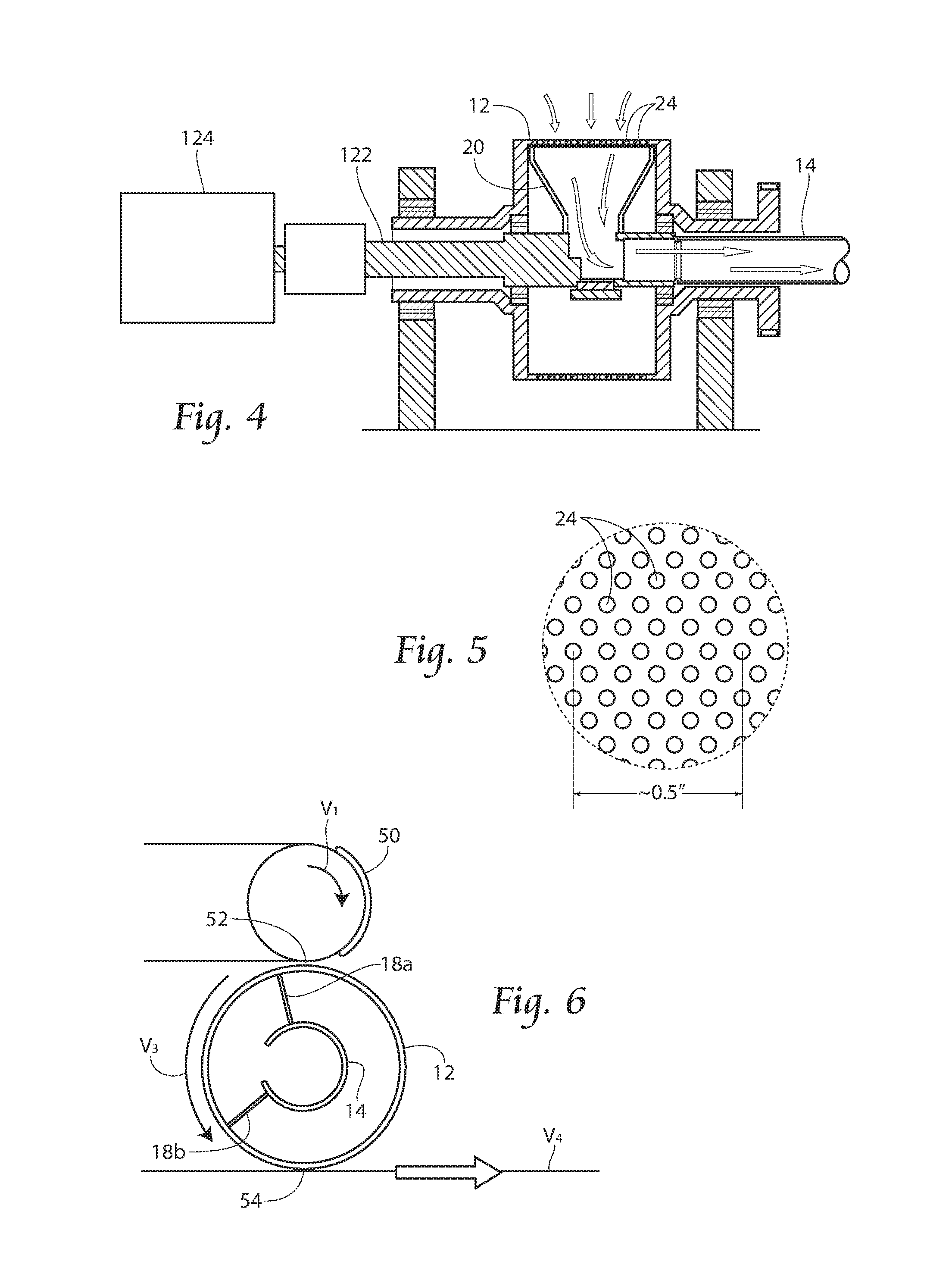
Referring now to FIG. 1, a side view of a system 10 comprising a porous roll 12 and internal independently rotatable vacuum manifold 14 carrying a discrete component of a disposable article 50 between an acquisition point 52 and a deposition point 54 is shown.
A conveyor 32 carries discrete components 50 towards an acquisition point 52. At the acquisition point 52, control of the discrete component 50 is handed off to a porous roll and vacuum manifold combination 10. Vacuum is drawn through the vacuum manifold 14, and in particular through a hollow shaft of the manifold 14, towards a vacuum application zone 16. This vacuum withdrawal action draws air through voids or pore spaces 24 of porous roll 12. This in turn draws and retains discrete component 50 to an exterior surface of porous roll 12, when desired. As porous roll 12 rotates, it carries discrete component 50 from the acquisition point 52 to deposition point 54. At deposition point 54, control of the discrete component 50 is handed off to a carrier web or vacuum conveyor or a bonder, shown generally at 60. Alternatively, at deposition point 54, control of the discrete component 50 can be handed off to a second porous roll and vacuum manifold combination 10. Two manifold walls 18 proscribe the circumferential area to which vacuum is applied to pores 24 of porous roll 12.
Referring now to FIG. 2, the structure of the system 10 is described more fully. An independently driven hollow manifold shaft 14 is coupled to a vacuum manifold defined by sidewalls 18 and end walls 20 of the vacuum application zone 16. The vacuum manifold application zone 16 is configured to fit within porous roll 12 as shown in FIG. 1, through a shaft void 40 in porous roll 12 receiving independently driven hollow manifold shaft 14, through which vacuum is drawn. Porous roll 12 is provided with sidewalls 22 which enable ambient air to enter the interior of porous roll 12. Nonporous zone 62 can be supplied on the porous roll 12 to delineate a cross-machine direction extent of vacuum commutation through pores 24. Porous roll 12 is preferably rotated independently of the manifold shaft 14, porous roll 12 being rotated by a drive motor 124 which rotates a drive belt 120 which is coupled to a porous roll driveshaft 122 coupled the porous roll 12. In this manner, it is possible to rotate the manifold shaft 14 and associated vacuum application zone 16 independent of the rotation of the porous roll 12.
Referring now to FIG. 3, it is possible to configure the manifold sidewalls 18 at different circumferential spacings to define different smaller or larger zones of vacuum commutation to the exterior surface of porous roll 12.
Referring now to FIG. 4, a side view of the porous roll 12 and internal independently rotatable vacuum manifold shaft 14 which vacuum is applied as shown. Ambient air flows through the porous roll 12, through pores 24, toward the lower pressure vacuum application zone 16 to manifold shaft. 14, and particularly through shaft 14 by action of a vacuum source (not shown). Motor 124 is operable to rotate shaft 122 carrying porous roll 12.
Referring now to FIG. 5, an exemplary size and configuration of pores 24 of the porous roll 12 is shown. It can be seen that preferably pores 24 are quite small in order to reduce the amount of air volume required of the system, and to prevent airborne contaminants such as pulp fluff fibers and non woven plastic fabric fibers from plugging the holes. In addition, the exemplary size of the pores 25 should be small enough that the fibers of the material in the article being transferred block some, all or preferably a majority of the surface area of each pore and thereby approximates a complete seal at the overlap of the fibers and the pores. This increases the force that holds the article to the porous roll 12 while reducing vacuum supply sizing. Further, reducing the pore size enables the distance between pores to be reduced while maintaining the same ratio of total pore opening area to closed (non porous) area of the porous drum 12. This minimizes the potential for an edge of the article from landing in a non porous area of the porous drum and thereby minimizes the potential for the edge of the article to fold back upon itself because it is not held down against the surface of the porous roll.
Referring now generally to FIGS. 6-13, side views of a sequence of operation of the rotatable porous roll and internal independently rotatable vacuum manifold transporting a discrete component of a disposable article between acquisition point 52 and a deposition point 54 is shown.
Beginning the sequence with reference to FIG. 6, discrete element 50 approaches acquisition point 52 at a velocity V1. Trailing manifold wall 18a rotates within porous roll 12, until it reaches a position immediately downstream of the acquisition point 52. At that point, the trailing manifold wall stops, or V2 goes to zero, and remains in this position until a leading edge of discrete element. 50 reaches acquisition point 52. Referring now to FIG. 7, as porous roll 12 rotates at V3 and manifold shaft 14 does not rotate, vacuum is applied through pores 24 of porous roll 12 to carry discrete element 50 from the acquisition point 52 to a position where the trailing edge of discrete element 50 reaches trailing manifold wall 18. Manifold shaft 14 then accelerates to V2 and transports discrete element 50 to deposition point 54. Referring now to FIG. 8, in a preferable embodiment, the circumferential distance between leading manifold wall 18a and trailing manifold wall 18b approximates a machine direction length of discrete element 50; however, the circumferential distance between leading manifold wall 18a and trailing manifold wall 18b can be longer or shorter than the machine direction length of discrete element 50. During the portion of the sequence shown in FIGS. 7 and 8, it is preferable that V2 equals V3, namely that the manifold shaft 14 and the porous roll 12 are rotating in the same direction at the same speed.
Referring to FIG. 9, as the leading edge of discrete element 50 reaches deposition point 54, rotation of the manifold shaft 14 stops, or V2 goes to zero, while porous roll 12 continues to rotate at V3. At this point, a handoff sequence begins, where control over discrete element 50 is handed off to a secondary operation 60 moving discrete element 50 at V4, secondary operation 60 for exemplary purposes comprising depositing the discrete element. 50 to be transported onto a carrier web, or onto a vacuum conveyor, to a bonder, to an additional system 10 comprising a porous roll 12 and internal independently rotatable vacuum manifold 14, a bonding unit, or otherwise.
Though not necessary, if desired to assist handoff, in an alternate embodiment (not shown) a blow-off system can be incorporated to operate with the commutating manifold 16 to positively push air through the pores 24 of porous roll 12. To implement a blow-off system, a rotary union can be used to attaching a blow off to the manifold (or even integrating it into the internal manifold itself). In another embodiment (not shown), a blowoff could assist to clear the pores 24 of porous rolls 12 of debris (such as material fibers) should debris accumulate in the pores 24.
Referring to FIG. 10, as the handoff sequence of control over discrete element 50 continues, V2 remains at zero, while V3 remains constant. Referring to FIG. 11, handoff of discrete element 50 to secondary operation 60 is complete. Referring to FIG. 12, the handoff sequence has concluded and V2 accelerates from zero to a speed greater than zero, in order to return trailing edge 18 to acquisition point 52, as shown in FIG. 13.
In another aspect of the invention, the drums and vacuum chambers have variable motion profiles. Because of the variable motion profiles, it is possible to accelerate or decelerate the speed of the unit to change the spacing between the discrete elements being transported. Several motion profiles of V1, V2, V3 and V4 relative to one another are possible. Such a motion profile could be: for trailing edge 18a to wait at material pickup location 52 (V2 is zero), next when portion of discrete element finishes acquisition at point 52, V2 increases; and the V2 is matched with V3, also the speed of discrete element 50, and then for V2 to exceed V3 on approach to deposition point 54 to allows time to slow manifold 14 without losing vacuum on the leading edge of the patch or to accelerate the speed of the patch to V4 in the case where V4 is greater than V3; next to reduce V2 to zero at deposition point 54; next to repeat the sequence.
It is possible to use multiple internal vacuum application zones 16 by creating additional walls 18a and 18b, connecting through a void space in shaft 14.
It is also possible for V2 to be in the opposite direction as V3, if desired for control in a preferred motion profile.
In an exemplary embodiment of a system that uses vacuum to hold a discrete element to the surface of a rotating drum, all of the air that flows from atmosphere into the pores of the drum would be oriented such that the direction of the airflow would be perpendicular to the surface of the drum. Any airflow in the cross machine direction or machine direction of the system has the potential to create forces on the edges of the discrete element which can cause the discrete element to fold back upon itself. (The discrete element is most susceptible to have edge folding occur as the discrete element transfers between drums.) Referring now to FIG. 14, a demonstrative side view of rotating bodies 200 and 300 and air flow patterns is shown. Upstream of the tangent between the two rolls 200 and 300, air into the low pressure zones 202 of the upper drum 200 travels from atmosphere and 30.times. of the lower drum 300. If the distance between the surfaces of the drums is adequately large, air can flow from the atmosphere surrounding the drums in a direction approximating perpendicular to the drum surfaces. However, if the distance between the drum surfaces is reduced incrementally, a distance will be reached where there is not adequate space between the drums to enable the air to flow in the optimum direction. As the distance between the rolls is further reduced, the direction of the airflow into the drum surfaces becomes less perpendicular to the drum surfaces and the potential for discrete element fold over increases. Atmospheric air can enter the system from the upstream side of tangent point of the drums 200 and 300, and some air can rush downstream from the higher pressure zone towards the downstream side of the transfer point (not shown). Because so much air is drawn in to create the low pressure zone in prior art vacuum system design, air velocity can undesirably cause patches carried by the drum (not shown) to behave erratically, and lead to flipping over of leading, trailing, or side edges. It has been found that even a small change in the air conditions at the transfer point can create imperfections and unrepeatability. To solve this problem, the system of the present invention limits the amount of airflow in the zone on the upstream side of the tangent part of the rolls 200 and 300, so the system does not undesirably reduce pressure, causing air to inrush. Because the bottom drum 300 of the present invention is supplied at least in part at atmospheric pressure, air can flow from the interior region of the bottom drum 300 to satisfy the need for air in the low pressure area 202 of the top drum 200.
FIG. 15 is a demonstrative side view of rotating bodies 200 and 300 and air flow patterns, with this configuration showing two low pressure zones 202 and 302, one in each of the top and bottom rotating drums 200 and 300 respectively. A patch 50 is shown being transferred from the top drum 200 to the bottom drum 300, but it is understood that in an operating system, the handoff of the patch 50 is going to be upstream handoff to a downstream unit in the machine direction.
To optimize the air flow of the system and minimize undesirable air flow patterns, it has been found advantageous to avoid locating low pressure zones 202 and 302 opposite of one another in a rotating system. Avoiding adjacent low pressure zones allows atmospheric air to flow into the low pressure zones 202 and 302 as intended, without undesirable turbulence that could be transmitted to the carried web or patch.
As shown in FIG. 15, low pressure zone 202 on the top drum 200 leads up to the tangent point, between the top drum 200 and bottom drum 300, and a low pressure zone 302 trails the tangent point on the bottom roll 300. It has been found that this configuration minimizes the undesirable inrush of air from the upstream side of the tangent point. Downstream of the tangent point, the interior (center) of the top drum 200 is exposed to atmospheric pressure, and this zone assists to satisfy air demand into the low pressure zone 302 of the bottom drum 300. Conversely, upstream of the tangent point, the interior (center) of the bottom drum 300 is exposed to atmospheric pressure, and this zone assists to satisfy air demand into the low pressure zone 202 of the top drum 200. The general principle is that it has been found advantageous in material handling to avoid low pressure zones opposite of one another while handling a web or a patch 50.
FIG. 16 is a close-up view of one pattern of micro vacuum commutation ports 24. In some systems, drums or other carrying structures (such as pucks) have vacuum commutation ports that have sparsely spaced port configurations, with the ports sometimes spaced around the perimeter of a discrete patch of material (or continuous webs) to be carried by the structure. In the present invention, micro vacuum commutation ports 24 can be used. These micro vacuum commutation ports 24 can have a pattern density more evenly distributed across the entire surface of the patch (in contrast to around the periphery). Because the system of the present invention can use less air (and energy, and in turn create less noise), a smaller amount of airflow is required to be generated by the vacuum system. In the present invention, a smaller hole diameter (for example, on the order of 0.003''-0.015'') can generate the holding force necessary to hold webs commonly used in the manufacturing process, such as non-woven webs. Such hole diameters result in a surface area of a representative void space of between about 7.times.10-6 square inches and 1.8.times.10-4 square inches each. This pore size has been discovered to be advantageous to securely hold individual fibers of a typical nonwoven of a denier of less than 1, to approximately 20 denier, and in some preferred nonwovens, 10-60 .mu.m diameter; however other nonwovens have 0.1 .mu.m diameter-300 .mu.m diameter. Typical nonwoven construction comprises many tiny bond points to which connect individual fibers of the essentially random fiber orientation. The microporous structures described above advantageously align with a holding force effective amount of these bond points in nonwoven to provide secure control over nonwovens.
A porous structure, such as drums 200, 300, or any of the disclosed pucks, can be provided with micro vacuum commutation ports 24 to, preferably: 1) reduce airflow requirements in the system; 2) provide more complete sealing of the pores and thereby increase holding forces on the discrete article; 3) minimize "dead zones" or areas with no inward air flow, between pores to minimize the potential for discrete article edge flip backs.
Such small micro vacuum commutation ports 24 can be manufactured for instance by electron drilling techniques, chemically etched, or drilled on thin foil. The thin foil construction, if used, is preferably supported by an underlying support structure for providing rigidity to the surface of the puck or drum. These techniques can require fairly thin gauge metal to be used in construction of the article carrying surfaces, resulting in a mask type structure which may be used over a full vacuum zone to limit inertia. In this embodiment, an air-permeable cylinder wall, or a buildup of air-permeable support structure could be covered by a micro-pore screen containing micro vacuum commutation ports 24. Such a mask type structure could be desired for instance, in high speed applications, to reduce inertia.
Non-woven material commonly used in disposable product manufacturing (e.g., diapers, feminine hygiene products) has individual fiber diameters of in the range of approximately 0.005''. In the prior art vacuum commutation port designs, a port of, for instance, 1/8'' diameter (which can be less or more) causes air to flow around the fibers of the nonwoven, and through the nonwoven generally. The holding force of vacuum commutation ports of the prior art is referred to as vacuum, though the holding force is more wind resistance applied to the nonwoven than true vacuum. In the present invention, micro vacuum commutation ports 24, which are near in size or smaller than the fibers of the nonwoven causes the micro vacuum commutation ports covered by an individual fiber of the nonwoven to be sealed off partially or completely. The micro vacuum commutation port 24 arrangement of the present invention does not rely as much, if at all, on air flow or wind resistance like the prior art, but instead on a static pressure differential.
The micro vacuum commutation ports 24 of the present invention are not necessarily as small as individual fibers, although such small ports 24 are useful and within the scope of the present invention. For instance, spunbond nonwoven has overlapping individual fibers, which can be embossed and bonded to one another. The micro vacuum commutation ports 24 of the present invention can be sized smaller than the bond patters of the spunbond nonwovens. By using micro vacuum commutation ports 24 of the present invention, it has been found that it is not necessary to engage each fiber, or each bond between fibers, and it is likewise not necessary that each micro vacuum commutation port have an overlying fiber. Sufficient holding force can be generated by the micro vacuum commutation ports 24 if, for any given discrete portion of a web, or a segment of a continuous web, a fraction of the fibers are coupled with a fraction of the micro vacuum commutation ports 24 in the targeted area to be carried and controlled (e.g., transferred, deposited).
Regarding density of the micro vacuum commutation ports 24 on a given structure, micro vacuum commutation ports 24 can be configured to comprise between 5%-50% of the surface area of the carrying structure (e.g., puck or drum). This range of surface area has been found to first, provide sufficient vacuum holding force; yet second, to retain enough strength for durable operation.
One additional benefit of the micro vacuum commutation port structure 24 is that the article carrying structure is less prone to contamination from pulp fiber and dust, because the micro vacuum commutation port structure is so small that it is difficult for contaminants to enter the structure.
Referring now to FIG. 17 is a side view of a prior art puck structure 500 is shown.
In the configuration exemplified by FIG. 17, ambient air leaves a low pressure zone upstream of the tangent between puck 500 and rotating drum 400. Because surfaces of both puck 500 and drum 400 are open to a vacuum chamber, this results in a low pressure zone between surfaces, which undesirably causes air to inrush from the sides and ends of the surfaces. The ambient air inrush from between where air is drawn into drum 400, and where air is drawn into puck 500 can disturb a patch on a drum 400 or puck or being as the patch is transferred. In the current system, at the moment of transfer, and at the transfer point, a transfer assist sequence (shown in arrows leaving the interior of drum 400) assists patch or web transfer from drum 400 onto puck 500 (or off of a puck as the case may be) by using a blast of pressurized air at that specific location (the transfer point) to blow the patch off the drum 500 and onto the puck 400 receiving the patch. The pressurized air from drum 400 can undesirably blow into the puck 500, and the extra air movement challenges the efficacy of the transfer or patch handoff.
In some prior art puck systems, two zones 1 and 2 are created at the puck surface, so that vacuum to these zones 1 and 2 can be independently controlled. Zone 1 can have applied vacuum while zone 2 has no applied vacuum. Alternatively, zone 2 can have applied vacuum while zone 1 has no applied vacuum. The on/off sequence is principally dictated by whether the puck 500 is receiving a patch or handing off a patch. It is desirable in certain handoff or receiving operations to, at a leading edge of the puck 500 in zone 1, apply vacuum to receive the leading edge of the received patch. But when it comes time to hand off the patch to the next equipment downstream, it is desirable to turn vacuum off of zone 1 to hand the patch off and relinquish control of the patch to the next piece of equipment, while retaining the patch with vacuum applied in zone 2. The desired blowoff to assist patch handoff can undesirably minimize the vacuum present in the puck 500 in zone 1 at that point.
In conventional vacuum puck designs, the pucks have cross machine direction air chambers that are connected to the surface of the puck 500. As the puck 500 travels, the air chambers move between high and low pressure zones of a vacuum manifold, and this results in air flowing into or out of the surface of the puck 500. This airflow and the associated pressure differentials will either cause a material patch to be attracted or repelled from the puck surface 500.
Still referring to FIG. 17, one shortcoming of the prior art is that ports 502 which commute vacuum to puck 500 are located remotely from the puck 500. The control for turning vacuum on or off at zones 1 and 2 is therefore remote from the puck 500. This remote arrangement undesirably creates lag time for high speed switching of vacuum on and off in zones 1 and 2. Because some of the turner pucks of the prior art, for instance those disclosed in U.S. Pat. No. 8,172,977 (incorporated by reference), rotate both in the machine direction and cross machine direction at the same time, it is impractical to use a conventional combination of a side vacuum manifold aligning with cross machine direction air chambers. Therefore, the air passages between the puck 500 and the vacuum chamber are routed through the center of the pucks 500. This results in relatively long airflow passage ways between the surface of the puck 500 and the vacuum supply manifold (not shown). This restricts the speed at which the direction of airflow at the surface of the puck 500 can be reversed. The remoteness of the vacuum manifold from the puck 500 is difficult to implement with pucks with multiple discrete zones that require quick changes in airflow direction.
Referring still to FIG. 18, a side view of a puck structure 610 with micro vacuum commutation ports 24 and valved and zoned vacuum commutation porting is shown. As with the example shown in FIG. 15 of two adjacent vacuum rolls that transfer a patch of material from one roll to the other roll, the same airflow and micro-perforated surface improvements can be made to a system that replaces one or both of the full rolls with vacuum pucks 610 that behave as partial rolls.
Instead of two zones 1 and 2 of the system shown in FIG. 17, the puck 610 of FIG. 18 can be made with multiple zones, 1'-10' or more or less for instance. Zones 1'-10' can either be open to the vacuum chamber (not shown) through ports 502 or open to the atmosphere. With the segmented vacuum zone 1-10 configuration on the puck 610, the system requires far less (if any) blow off pressure from the drum 400. As the puck 610 passes the tangential point, each of the zones 1-10 are selectively turned on in an acquisition sequence, in order to gain control of the patch as the puck 610 rolls past the drum 400.
A rotating valve disk 600 is used to rapidly control the application of vacuum air to each individual zone 1-10 in a controlled way. By sequential vacuum engagement, the undesirable low pressure zone at the transfer point between drum 400 and 610 is minimized if not eliminated, and there is therefore less turbulence or disruption of a carried patch at that point. Incorporating a valve mechanism 600 that can quickly switch airflow passages between a vacuum supply chamber and atmosphere in the puck 610 reduces the level of the air passage lengths to a level that will enable adequately rapid response. This allows for on/off times of zones 1'-10' to be nearly instantaneously controlled because of the proximity between the vacuum commutation and the vacuum surface of the puck 610. This proximity also enables a rotating puck 610 to have multiple air flow zones 1-10 which can be controlled to switch the airflow direction at the surface of the puck 610. By using multiple zones 1-10, airflow at the surface of the puck 610 can be optimized to closely approximate the airflow characteristics of a two roll system shown in FIG. 15.
By locating the rotating valve disk 600 or other form of vacuum control inside of the puck 610 assembly itself or in close proximity to the puck, this puts the mode of control into the puck 610, and minimizes lag time for on/off operations. Zone control in the puck 610 is adjacent to the puck surface.
Still referring to FIG. 18, internal air passages 602 from valve disk 600 are used commute vacuum from ports 502 to the surface of puck 610.
Drum 400 displays a transition position where air flow direction switches from inward (arrows pointing into drum 400) to outward (arrows pointing out of drum 400). In a preferred embodiment, this transition position is offset either upstream or downstream of the discrete article transfer (handoff by acquisition or deposition) positions by a selected amount, to compensate for variations in the system.
Sill referring to FIG. 18, the rotatably driven multi-zoned vacuum puck 610 used to turn discrete articles 180 degrees and transport them from a pickup position (where for example a leading edge or zone 1' of puck 610 first begins acquisition of discrete articles, see, e.g., acquisition point 52 of FIG. 1) to a deposition position (where for example discrete articles are laid down on a running web, see, e.g., deposition point 54 of FIG. 1). The repositioning of articles shown for example in FIGS. 5-17 of U.S. Pat. No. 8,016,972, incorporated herein by reference. An external vacuum manifold (not shown) applies vacuum through internal vacuum passages to zones 1'-10' in the puck as previously described when the zones 1'-10' are located in positions between just upstream of the acquisition position, to the downstream side of the acquisition position, and the upstream side of the deposition position. When a vacuum passage 1'-10' is engaged with the vacuum manifold, ambient air flows into the pores on the surface of the puck 610 in order to hold material against the puck's external surface. Conversely, when a vacuum passage 1'-10' is not engaged with the vacuum manifold, ambient air flows can flow out of the pores 24 on the surface of the puck 610.
To accomplish this, the vacuum puck 610 rotates such that the surface of the puck 610 is traveling at the same speed as the incoming discrete element carried by drum 400. The external vacuum manifold is positioned such that ambient air flows outward through the surface of the puck 610 at points immediately upstream of the acquisition point and ambient air flows inward through the pores in the surface of the puck 610 at points immediately downstream of the pick-up point. As the leading edge of the discrete article reaches the acquisition point, air flowing from the atmosphere into the vacuum puck 610 forces the leading edge of the discrete article to transfer to and be held against the surface of the puck 610. Likewise, the remainder of the discrete article will transfer onto the porous roll or puck 610 as the porous roll or puck 610 advances.
After the trailing edge of the discrete article is transferred to the surface of the vacuum puck 610, the puck continues to rotate and thereby transports the discrete article to the deposition point. The vacuum applied external vacuum manifold ends immediately upstream of the deposition point such that ambient air flows into the puck 610 upstream of the deposition point and ambient air flows out of the puck 610 downstream of the deposition point. As the leading edge of the discrete article passes the deposition point, air flowing out of the puck 610 and into the vacuum zone of the receiving device forces the discrete article to transfer from the surface of the porous roll onto the receiving device. Likewise, the remainder of the discrete article transfers onto the receiving device as the discrete article continues to advance. After the discrete article has transferred to the receiving device, the vacuum puck returns to its original orientation and position upstream of the pickup point and the cycle repeats.
Likewise, the remainder of the discrete article transfers onto the receiving device as the discrete article continues to advance. After the discrete article has transferred to the receiving device, the vacuum puck returns to its original orientation and position upstream of the pickup point and the cycle repeats. In such a puck system, ambient air can flow from the inside of the puck outward to: 1) eliminate or minimize overlapping low pressure zones which in turn eliminates or minimizes in-rushes of air at the edges of the patch; 2) results in an airflow direction that is approximately perpendicular to the surface to which the discrete element is riding upon. Such a puck system also can utilize micro-pores to: 1) reduce airflow requirements; 2) provide more complete sealing of the pores and thereby increases holding force on the discrete article; and 3) minimize dead zones between pores to minimize the potential for discrete article edge flip backs.
Referring now to FIG. 19, a perspective view of puck 610 is shown. Puck 610 is advantageously equipped with micro vacuum commutation ports 24, which commute vacuum, for instance by the arrangement shown in FIG. 18.
Referring now to gig. 20, an exemplary puck 610 is shown with the capability of both rotation and revolution, as previously described.
FIGS. 21A-21F display a side view of a sequence of operation of an anvil 900/drum 902 feeding discrete pieces 50A, 50B to a series of porous roll/internal vacuum manifold combinations 10/12/14A and 10/12/14B positioned about the drum 902 for passing and spacing discrete pieces 50A and 50B to a running web 60. Porous roll/internal vacuum manifold combinations 10/12/14 are preferably operable as described previously, with manifold 14 rotating independently of roll 12, allowing the rotational velocities of each to vary from one another (V2 for manifold 14, and V3 for roll 12) and create unique operational sequences. One such unique sequence is the operation displayed in FIGS. 21A-21F.
Referring first to FIG. 21A, an incoming web 49 is carried by a conveyor 30 to an anvil 900/drum 902 combination. Incoming web 49 is severed into sequential alternating discrete pieces 50a, and 50 B, and this operation can be a slip/cut technique as is known in the art.
In one embodiment, porous roll/internal vacuum manifold combinations 10/12/14A and 10/12/14B are positioned about drum 902. In the illustrated embodiment, two porous roll/internal vacuum manifold combinations 10/12/14A and 10/12/14B are used, although more or less could be deployed depending on the desired operational sequence. A first porous roll/internal vacuum manifold combination 10/12/14A is positioned upstream of a second porous roll/internal vacuum manifold combinations 10/12/14B. The first porous roll/internal vacuum manifold combination 10/12/14A is positioned and operated to pick up every other of the discrete pieces 50A and 50 B, the first combination picking up discrete pieces 50A leaving behind discrete pieces 50B for the second porous roll/internal vacuum manifold combination 10/12/14B to acquire, accelerate and deposit. Preferably simultaneously, each of the porous roll/internal vacuum manifold combinations 10/12/14A and 10/12/14B acquire discrete pieces 50A and 50B, respectively at their own acquisition points 52, as shown in FIG. 21B.
Both porous roll/internal vacuum manifold combinations 10/12/14A and 10/12/14B then accelerate discrete pieces 50A and 50B, respectively to their deposition points 54. At deposition points 54, discrete pieces 50A and 50B are deposited onto an incoming web 60 as shown in FIG. 21E, and the incoming web can come into contact with discrete pieces 50A and 50B by either a close-gap spacing arrangement between porous roll/internal vacuum manifold combinations 10/12/14A and 10/12/14B and the web, or a bump method such as disclosed in U.S. Pat. No. 7,811,403 incorporated herein by reference. Alternatively, a nip point underneath deposition points 54 could be ultrasonic bonding stations (not shown), which could then bond discrete pieces 50A and 50B to traveling web 60 simultaneously with deposition. This sequence allows for discrete pieces 50A and 50B to be deposited onto running web 60 at a first spacing D1 between pieces 50A and 50B, and allows for a second spacing D2, preferably product pitch, between two pieces 50A in a sequence and spacing D2 also between two pieces 50B in a sequence. D1 and D2 can also be arranged so that D2 is twice D1. The web as shown in FIG. 22 can then be severed into individual products at several locations, either through pieces 50A and/or 50B, or between any of 50A and 50B, as desired.
As shown in FIG. 22, a top perspective view of an exemplary placement sequence of discrete pieces 50A and 50B about sides of a running web 60, a pair of discrete pieces 50A, and a pair of discrete pieces 50B can be deposited at the same placement in a machine direction, for instance in placement of ear tabs or other discrete components about a chassis web 60 of a diaper. Products as shown in FIG. 22 can then be severed in the cross machine direction, either between
To accomplish a D1/D2 placement of discrete pieces 50A and 50B as shown in FIG. 22, FIG. 23 shows an exemplary transfer drum velocity speed profile for porous roll/Internal vacuum manifold combinations 10/12/14A and 10/12/14B during an acquisition and deposition sequence. Although FIG. 23 displays an exemplary transfer drum velocity speed profile for porous roll/internal vacuum manifold combinations 10/12/14A and 10/12/14B, actual speeds can vary higher or lower than those displayed. As can be seen, referring to FIG. 23 as well as the sequence depicted in FIGS. 21A-21F, during a period of acquisition of an individual patch 50, the transfer drum moves at a constant velocity, preferably the same velocity as the drum 902. During this period, referring for example to V1 (representing in this embodiment the velocity of drum 902), V2 (representing in this embodiment the velocity of manifold 14), V3 (representing in this embodiment the velocity of porous roll 12), and V4 (representing in this embodiment the velocity of web 60) of FIG. 6, V1=V2=V3<V4. At the completion of patch 50 acquisition by one of the porous roll/internal vacuum manifold combinations 10/12/14A and 10/12/14B, the porous roll/internal vacuum manifold combination 10/12/14 accelerates to equal V4 of the running web 60, until a deposition period of deposition of patch 50 to web 60, when V1<V2=V3=V4. Next, in preparation for acquisition of the next patch 50 in sequence, porous roll/internal vacuum manifold combinations 10/12/14A and 10/12/14B decelerate back to equal V1. The process then repeats.
As multiple porous roll/internal vacuum manifold combinations 10/12/14A and 10/12/14B work in conjunction, each porous roll/internal vacuum manifold combinations 10/12/14A and 10/12/14B processing every other discrete article 50A or 50B in a continuous stream of discrete articles 50 to change the spacing between discrete articles 50A and 50B, or successive discrete articles 50A, by large amounts such as a 5:1 spacing increase. In this manner, at least two spacings, D1 and D2, can be achieved between successive pieces.
The foregoing is considered as illustrative only of the principles of the invention. Furthermore, since numerous modifications and changes will readily occur to those skilled in the art, it is not desired to limit the invention to the exact construction and operation shown and described. While the preferred embodiment has been described, the details may be changed without departing from the invention, which is defined by the claims.
* * * * *
D00000
D00001
D00002
D00003
D00004
D00005
D00006
D00007
D00008
D00009
D00010
D00011
XML
uspto.report is an independent third-party trademark research tool that is not affiliated, endorsed, or sponsored by the United States Patent and Trademark Office (USPTO) or any other governmental organization. The information provided by uspto.report is based on publicly available data at the time of writing and is intended for informational purposes only.
While we strive to provide accurate and up-to-date information, we do not guarantee the accuracy, completeness, reliability, or suitability of the information displayed on this site. The use of this site is at your own risk. Any reliance you place on such information is therefore strictly at your own risk.
All official trademark data, including owner information, should be verified by visiting the official USPTO website at www.uspto.gov. This site is not intended to replace professional legal advice and should not be used as a substitute for consulting with a legal professional who is knowledgeable about trademark law.